


PROFESSIONAL AUDIO WORKSTATION
Owner’s Manual
Keep This Manual For Future Reference.
E
FCC INFORMATION (U.S.A.)
1.IMPORTANT NOTICE: DO NOT MODIFY THIS UNIT! This product, when installed as indicated in the instructions contained in this manual, meets FCC requirements. Modifications not expressly approved by Yamaha may void your authority, granted by the FCC, to use the product.
2.IMPORTANT: When connecting this product to accessories and/or another product use only high quality shielded cables. Cable/s supplied with this product MUST be used. Follow all installation instructions. Failure to follow instructions could void your FCC authorization to use this product in the USA.
3.NOTE: This product has been tested and found to comply with the requirements listed in FCC Regulations, Part 15 for Class “B” digital devices. Compliance with these requirements provides a reasonable level of assurance that your use of this product in a residential environment will not result in harmful interference with other electronic devices. This equipment generates/uses radio frequencies and, if not installed and used according to the instructions found in the users manual, may cause interference harmful to the operation of other electronic devices. Compliance with FCC regulations does not guarantee that interference will not occur in all installations. If this product is found to be the source of interference, which can be determined by turning the unit “OFF” and “ON”, please try to eliminate the problem by using one of the following measures: Relocate either this product or the device that is being affected by the interference. Utilize power outlets that are on different branch (circuit breaker or fuse) circuits or install AC line filter/s. In the case of radio or TV interference, relocate/reorient the antenna. If the antenna lead-in is 300 ohm ribbon lead, change the lead-in to coaxial type cable. If these corrective measures do not produce satisfactory results, please contact the local retailer authorized to distribute this type of product. If you can not locate the appropriate retailer, please contact Yamaha Corporation of America, Electronic Service Division, 6600 Orangethorpe Ave, Buena Park, CA 90620
The above statements apply ONLY to those products distributed by Yamaha Corporation of America or its subsidiaries.
ADVARSEL! Lithiumbatteri—Eksplosionsfare ved fejlagtig
håndtering. Udskiftning må kun ske med batteri af samme fabrikat og type. Levér det brugte batteri tilbage til leverandoren.
VARNING
Explosionsfara vid felaktigt batteribyte. Använd samma batterityp eller en ekvivalent typ som rekommenderas av apparattillverkaren. Kassera använt batteri enligt fabrikantens instruktion.
VAROITUS
Paristo voi räjähtää, jos se on virheellisesti asennettu. Vaihda paristo ainoastaan laitevalmistajan suosittelemaan tyyppiin. Hävitä käytetty paristo valmistajan ohjeiden mukaisesti.
WARNING: THIS APPARATUS MUST BE EARTHED
IMPORTANT
THE WIRES IN THIS MAINS LEAD ARE COLOURED IN ACCORDANCE WITH THE FOLLOWING CODE:
GREEN-AND-YELLOW : EARTH
BLUE : NEUTRAL
BROWN : LIVE
As the colours of the wires in the mains lead of this apparatus may not correspond with the coloured markings identifying the terminals in your plug, proceed as follows:
The wire which is coloured GREEN and YELLOW must be connected to the terminal in the plug which is marked by the letter E or by the safety earth symbol  or coloured GREEN and YELLOW.
The wire which is coloured BLUE must be connected to the terminal which is marked with the letter N or coloured BLACK.
The wire which is coloured BROWN must be connected to the terminal which is marked with the letter L or coloured RED.
*This applies only to products distributed by YAMAHA KEMBLE MUSIC (U.K.) LTD.
C A U T I O N
RISK OF ELECTRIC SHOCK
DO NOT OPEN
CAUTION: TO REDUCE THE RISK OF ELECTRIC SHOCK, DO NOT REMOVE COVER (OR BACK). NO USER-SERVICEABLE PARTS INSIDE. REFER SERVICING TO QUALIFIED SERVICE PERSONNEL.
The above warning is located on the rear of the unit.
• Explanation of Graphical Symbols
The lightning flash with arrowhead symbol within an equilateral triangle is intended to alert the user to the presence of uninsulated “dangerous voltage” within the product’s enclosure that may be of sufficient magnitude to constitute a risk of electric shock to persons.
The exclamation point within an equilateral triangle is intended to alert the user to the presence of important operating and maintenance (servicing) instructions in the literature accompanying the product.

NEDERLAND
●Dit apparaat bevat een lithium batterij voor geheugen back-up.
●Raadpleeg uw leverancier over de verwijdering van de batterij op het moment dat u het apparaat ann het einde van de levensduur afdankt of de volgende Yamaha Service Afdeiing:
Yamaha Music Nederland Service Afdeiing Kanaalweg 18-G, 3526 KL UTRECHT
Tel. 030-2828425
●Gooi de batterij niet weg, maar lever hem in als KCA.
THE NETHERLANDS
●This apparatus contains a lithium battery for memory back-up.
●For the removal of the battery at the moment of the disposal at the end of the service life please consult your retailer or Yamaha Service Center as follows:
Yamaha Music Nederland Service Center Address: Kanaalweg 18-G, 3526 KL
UTRECHT Tel: 030-2828425
●Do not throw away the battery. Instead, hand it in as small chemical waste.

Important
Important
Read the following before operating the AW2816
■ Warnings
•Do not place a container with liquid or small metal objects on top of this unit. Liquid or metal objects inside this unit are a fire and electrical shock hazard.
•Do not allow water to enter this unit or allow the unit to become wet. Fire or electrical shock may result.
•Connect this unit’s power cord only to an AC outlet of the type stated in this Owner’s Manual or as marked on the unit. Failure to do so is a fire and electrical shock hazard.
•Do not scratch, bend, twist, pull, or heat the power cord. A damaged power cord is a fire and electrical shock hazard.
•Do not place heavy objects, including this unit, on top of the power cord. A damaged power cord is a fire and electrical shock hazard. In particular, be careful not to place heavy objects on a power cord covered by a carpet.
•To avoid possible electrical shock, do not install an I/O card, hard disk, or CD-RW drive in the unit while the power cable is connected to the AC outlet.
•Use the ground connector on the rear panel to securely ground the device. If the device is not grounded, you may suffer a dangerous electrical shock.
•If you notice any abnormality, such as smoke, odor, or noise, or if a foreign object or liquid gets inside the unit, turn it off immediately. Remove the power cord from the AC outlet. Consult your dealer for repair. Using the unit in this condition is a fire and electrical shock hazard.
•Should this unit be dropped or the cabinet be damaged, turn the power switch off, remove the power plug from the AC outlet, and contact your dealer. If you continue using the unit without heeding this instruction, fire or electrical shock may result.
•If the power cord is damaged (i.e., cut or a bare wire is exposed), ask your dealer for a replacement. Using the unit with a damaged power cord is a fire and electrical shock hazard.
•Do not modify the unit. Doing so is a fire and electrical shock hazard.
•Do not apply force to, disassemble, or modify the I/O card, the PC board of the hard disk, or the connectors on the unit. Otherwise, malfunction, fire, or electrical shock may result.
•If lightning begins to occur, turn off the power switch of the unit as soon as possible, and unplug the power cable plug from the electrical outlet.
•If there is a possibility of lightning, do not touch the power cable plug if it is still connected. Doing so may be an electrical shock hazard.
■ Cautions
•This unit has ventilation holes at the bottom to prevent the internal temperature rising too high. Do not block them. Blocked ventilation holes are a fire hazard.
•Hold the power cord plug when disconnecting it from an AC outlet. Never pull the cord. A damaged power cord is a potential fire and electrical shock hazard.
•Do not touch the power plug with wet hands. Doing so is a potential electrical shock hazard.
•Always touch a well-grounded metal surface or the like to fully discharge any static electric charge on your body and clothing before handling an I/O card or hard disk.
Neglecting this precaution can cause damage to the unit from static electricity.
•Be careful not to touch the leads (metal feet) on the rear side when handling an I/O card or hard disk. Touching the leads can cause contact defects.
•Use only the included power supply cable for this unit. Using other types may be a fire hazard.
■ Operating Notes
•The digital circuits of this unit may induce a slight noise into nearby radios and TVs. If noise occurs, relocate the affected equipment.
•Using a mobile telephone near this unit may induce noise. If noise occurs, use the telephone away from the unit.
•XLR-type connectors are wired as follows:
pin 1: ground, pin 2: hot (+), and pin 3: cold (–).
•Insert TRS phone jacks are wired as follows: sleeve: ground, tip: send, and ring: return.
•If the message “LOW BATTERY” appears when you turn on this unit, contact your dealer as soon as possible about replacing the internal data backup battery.
We recommend that you save the data on CD-RW drive or external SCSI device before replacing the battery.
•The performance of components with moving contacts, such switches, rotary controls, faders, and connectors, deteriorates over time. The rate of deterioration depends on the operating environment and is unavoidable. Consult your dealer about replacing defective components.
iv

Handling the CD-R/RW media
Please observe the following points when handling the disk.
Failure to do so may cause problems such as the recorded data being lost, the drive to malfunction, or the printed label to become blurred.
•Do not place the disk in locations of direct sunlight, high temperature, or high humidity.
•Do not touch either surface of the disk.
•Hold the disk at the edges. Gently wipe dust or dirt off of the recording surface of the disk.
•Do not wipe the disk with chemicals or detergents.
•Do not bend or drop the disk.
•Use an air duster or cleaner to remove dust. Vigorously rubbing the surface of the disk with a dry cloth may scratch the disk.
•Do not write on the disk or affix labels to it.
Storing produced data
Produced data can be lost due to breakdown or mistaken operation. We recommend that you store all important data on CD-R or CD-RW disks or other external storage medium.
Responsibility for loss of data, etc.
•Yamaha will accept no responsibility for any damages (including consequential or incidental) incurred by the customer or any third party as a result of loss or impairment of the data stored on the CD-R media, regardless of whether such loss could have been or actually was foreseen by Yamaha.
•Nor does Yamaha guarantee the media against any defect that may render it unusable.
Cautions for handling optional equipment
•For inquiries concerning I/O card, hard disk, or CD-RW drive handling, please consult your Yamaha dealer.
•Always switch off the power for the main unit and all peripherals, unplug the power cord for the main unit from the outlet, then disconnect the cables connecting the main unit with the peripherals before starting installation work.
•Wear thick gloves when working on this equipment to avoid cutting your hands on metal fittings or the like on the main unit, I/O card, hard disk, or CD-RW drive.
•Always touch a well-grounded metal surface or the like to fully discharge any static electric charge on your body and clothing before starting to work on this equipment.
•Take extreme care to avoid touching any terminals or board surface parts.
•In order to protect the electronic circuits of the I/O card, hard disk, CD-RW drive, etc. from damage due to static electricity, when handling any of this equipment, take the most extreme care to avoid touching IC leads or other electronic parts.
•Be careful not to drop any screws into the main unit. If you switch the power on with a dropped screw still in the main unit, the main unit may malfunction or break down. If a dropped screw can not be retrieved, consult your Yamaha dealer.
•If the hard disk or CD-RW drive breaks down, contact the store where you purchased that equipment.
Except for duplication for personal use or when there is no copyright problem, the duplication or transfer of commercially sold music/sound data without the permission of the copyright holder is prohibited. When using this equipment, please consult with a copyright specialist.
■ Warning
The Yamaha Professional Audio Workstation is designed to be used professionally and responsibly by recording industry professionals. The reproduction, distribution, or, in some instances, the public performance, of all or a portion of a sound recording or musical composition protected by copyright, without having obtained a proper license from the relevant copyright holders, may constitute copyright infringement and may otherwise violate copyright laws and other laws. In addition, laws (such as the Audio Home Recording Act and the Digital Millennium Copyright Act in USA) contain certain restrictions and requirements that may apply to your use of works protected by copyright and related information and data that may accompany such works. Violation of such laws may result in civil remedies and, in some cases, criminal liability.
Because violations of copyright laws may be serious offenses, you should consult a lawyer familiar with the law of copyright, including all laws that may be applicable to your use of the Workstation (such as the Audio Home Recording Act and the Digital Millennium Copyright Act in USA), if you have any questions regarding your intended use of all or parts of sound recordings or musical compositions protected by copyright.
v

Table of contents
Table of contents —Operation section—
Before you begin ..................... |
1 |
Checking the included items ................... |
1 |
Installing an internal hard disk ................ |
2 |
About the internal hard disk.......................... |
2 |
Installation .................................................... |
2 |
Installing a CD-RW drive......................... |
4 |
About the CD-RW drives .............................. |
4 |
CD-RW drive settings ................................... |
4 |
Installation procedure ................................... |
5 |
Removing the transport protection pad... |
7 |
Manual eject (emergency disc removal) ....... |
7 |
Attaching an external SCSI device........... |
8 |
About external SCSI devices ......................... |
8 |
Connection procedure .................................. |
8 |
Installing I/O card ................................. |
10 |
About I/O cards .......................................... |
10 |
Installation procedure ................................. |
10 |
Please observe the following points....... |
11 |
Turning the power on ................................. |
11 |
Setting the internal clock ............................ |
11 |
Turning the power off ................................. |
12 |
Chapter1 Parts and their functions13
Top panel............................................... |
13 |
Analog input/output section........................ |
13 |
WORK NAVIGATE section......................... |
14 |
UNIT section .............................................. |
14 |
MIXER section............................................. |
14 |
FADER MODE section................................ |
15 |
MIXING LAYER section .............................. |
15 |
Fader section .............................................. |
16 |
Display section ........................................... |
17 |
REC TRACK SELECT section ....................... |
18 |
RECORDER section .................................... |
18 |
AUTOMATION section .............................. |
19 |
SCENE MEMORY section ........................... |
19 |
CURSOR/JOG&SHUTTLE section............... |
19 |
LOCATE section.......................................... |
20 |
Transport section ........................................ |
21 |
Rear panel.............................................. |
22 |
Front panel ............................................ |
24 |
Chapter2 Welcome to the world |
|
of the AW2816 .......... |
25 |
Features of the AW2816........................ |
25 |
Mixer section .............................................. |
25 |
Recorder section......................................... |
25 |
CD-RW drive (option)................................. |
26 |
Other features ............................................. |
26 |
Signal flow within the AW2816............. |
27 |
Input patch ................................................. |
27 |
Input channels 1–8 ..................................... |
28 |
Return channels 1/2.................................... |
29 |
Recorder input patch .................................. |
29 |
Monitor channels 1–16............................... |
30 |
Digital cascade connection......................... |
30 |
Oscillator.................................................... |
30 |
Stereo output channel................................. |
31 |
Buses 1–8 ................................................... |
31 |
AUX buses 1–6 ........................................... |
31 |
Output patch .............................................. |
32 |
Internal effects 1/2 ...................................... |
32 |
Monitor output/headphone output.............. |
32 |
The track structure of the AW2816....... |
33 |
Audio tracks................................................ |
33 |
Virtual tracks............................................... |
33 |
The stereo track .......................................... |
33 |
About the display................................... |
34 |
Cursor ......................................................... |
34 |
Buttons........................................................ |
35 |
Knobs/faders/numerical boxes .................... |
35 |
Tabs ............................................................ |
35 |
Basic operation of the AW2816 ............ |
36 |
Accessing screens and pages ...................... |
36 |
Switching a button on/off............................ |
36 |
Editing the value of a fader/knob/numerical |
|
box ............................................................ |
36 |
Using the additional function buttons......... |
37 |
Inputting text............................................... |
37 |
Selecting a channel..................................... |
38 |
Chapter3 Let’s record on the |
|
AW2816 .................... |
41 |
Connections and setup .......................... |
41 |
Making connections ................................... |
41 |
Creating a new song ................................... |
42 |
Word clock settings .................................... |
44 |
Recording the first track ........................ |
46 |
Setting the input level ................................. |
46 |
Pairing two channels................................... |
47 |
Patching input signals to recorder inputs .... |
48 |
Adjusting the monitor level......................... |
50 |
Recording ................................................... |
51 |
Recording additional tracks |
|
(Overdubbing)...................................... |
52 |
Setting the input level ................................. |
52 |
Patching the input signal to the recorder input |
|
......................... |
52 |
Adjusting the monitor level......................... |
54 |
Applying the equalizer to the input signal... |
54 |
Applying the dynamics processor to the input |
|
signal......................................................... |
55 |
Recording ................................................... |
57 |
Mixing to the stereo track (Mixdown) ... |
58 |
Adjusting the mix balance .......................... |
58 |
Using the internal effects............................. |
59 |
Recording on the stereo track ..................... |
60 |
Saving your song.................................... |
62 |
Advanced techniques on the AW2816 .. |
63 |
Manually re-recording only a specific area |
|
(Manual Punch-in/out)............................... |
63 |
Automatically re-recording only a specific area |
|
(Auto Punch-in/out) ................................... |
64 |
Switching virtual tracks............................... |
66 |
Operating multiple faders together |
|
(Fader Groups)........................................... |
67 |
Operating multiple [ON] keys together |
|
(Mute Groups) ........................................... |
68 |
Using the Solo function .............................. |
69 |
Chapter4 Input/output patching71 |
|
Assigning signals to input channels/return |
|
channels (Input Patch).......................... |
71 |
Assigning signals to the recorder inputs |
|
(Recorder Input Patch)......................... |
73 |
Assigning signals to output jacks/output |
|
channels (Output Patch) ...................... |
74 |
Using the patch library .......................... |
76 |
Storing the patching settings to the library .. |
76 |
Recalling patching settings from the library 77 |
|
Inserting an external effect into a channel |
|
....................... |
78 |
Quickly assigning input signals to tracks |
|
(Quick Rec) .......................................... |
80 |
Chapter5 Using the internal |
|
effects ....................... |
83 |
About the internal effects ...................... |
83 |
Using AUX send/return to apply an effect 84 |
|
Check the patching..................................... |
84 |
Recalling an effect program from the library84 |
|
Switching between pre-fader/post-fader...... |
86 |
Adjusting the return level............................ |
87 |
Adjusting the send level.............................. |
87 |
vi
Table of contents
Inserting an effect into a specific channel |
|
...................... |
88 |
Change the patching.................................. |
88 |
Inserting the effect into a channel .............. |
88 |
Recalling an effect program ....................... |
89 |
Applying effects while you record ........ |
90 |
Change the patching.................................. |
90 |
Insert the effect into a channel ................... |
90 |
Start recording............................................ |
91 |
Adjusting the effect parameters ............ |
92 |
Saving an effect program ...................... |
93 |
Chapter6 Transport/Locate |
|
operations................. |
95 |
Transport key functions ........................ |
95 |
Fast forward-play/Fast reverse-play |
|
(the Shuttle function)........................... |
95 |
Searching for a point while you listen |
|
(the Nudge function) ........................... |
96 |
Searching for a point while viewing the |
|
waveform............................................. |
97 |
Rewinding for a specific distance |
|
(Rollback) ............................................ |
98 |
Repeatedly playing a specified region |
|
(A-B Repeat) ........................................ |
99 |
Locating to a specified point............... |
100 |
Locating to the zero location of the counter |
|
.................... |
101 |
Setting the relative time zero location...... |
101 |
Using various locate points to locate.. 102 |
|
Using markers to locate ...................... |
103 |
Editing the location of a locate point or |
|
marker ............................................... |
104 |
The relation between the Start point and time |
|
code ....................................................... |
105 |
Deleting a locate point/marker........... |
106 |
Deleting from within the screen............... |
106 |
Deleting by using key operations............. |
106 |
Chapter7 Editing tracks and |
|
virtual tracks........... |
107 |
Editing tracks and virtual tracks.......... |
107 |
Tracks, parts, and regions ................... |
108 |
Naming a track or region.................... |
109 |
Editing a virtual track name ..................... |
109 |
Editing a region name .............................. |
110 |
Editing the audio data of tracks 1–16 . 111 |
|
Editing entire Tracks................................. |
111 |
Editing by Part.......................................... |
113 |
Editing by Region..................................... |
114 |
Editing the audio data of virtual tracks |
|
1–8..................................................... |
116 |
Editing commands............................... |
118 |
Commands and parameters of the TRACK |
|
menu ...................................................... |
118 |
Commands and parameters of the PART |
|
menu ...................................................... |
121 |
Commands and parameters of the REGION |
|
menu ...................................................... |
125 |
Chapter8 Scene memory |
|
operations............... |
127 |
About scene memories........................ |
127 |
Parameters included in a scene................ |
127 |
About scene numbers .............................. |
127 |
Storing a scene.................................... |
128 |
Storing a scene by operations in the screen 128 |
|
Storing a scene by key operations............ |
128 |
Recalling a scene................................. |
129 |
Recalling a scene by operations in the screen |
|
...................... |
129 |
Recalling a scene by key operations ........ |
129 |

Editing the name of a scene ................ |
130 |
Protecting a scene............................... |
131 |
Changing the order of scenes ............. |
132 |
Chapter9 Using automix ......... |
133 |
About automix .................................... |
133 |
What is automix?...................................... |
133 |
What can be recorded in automix?........... |
133 |
How the automix is related to the song .... |
133 |
Creating a new automix...................... |
134 |
Recording and playing an automix ..... |
135 |
Recording fader operations in the automix135 |
|
Playing back the automix ......................... |
136 |
Recording additional fader operations of other |
|
channels.................................................. |
137 |
Recording additional mix elements .... |
138 |
Re-recording only part of the automix |
|
(Punch-in/out) ................................... |
139 |
Re-recording fader operations ............ |
141 |
Editing individual automix events ....... |
143 |
Storing an automix.............................. |
145 |
Recalling an automix .......................... |
146 |
Chapter10 Managing songs..... |
147 |
About songs ........................................ |
147 |
What is a song?......................................... |
147 |
Song structure........................................... |
147 |
Song recording time.................................. |
147 |
Saving the current song ...................... |
148 |
Loading a song .................................... |
149 |
Editing the song name/comment ........ |
150 |
Protecting a song ................................ |
151 |
Duplicating a song .............................. |
152 |
Deleting an unwanted song ................ |
153 |
Deleting unused audio data from a song |
|
(Optimize) ......................................... |
154 |
Importing mixer data from an existing song |
|
.................... |
155 |
Importing tracks from an existing song156 |
|
Chapter11 Using the internal hard |
|
disk/external storage |
|
devices ................... |
159 |
Formatting the internal hard disk ....... |
159 |
Formatting an external drive .............. |
160 |
Erasing CD-RW media ........................ |
161 |
Backing up songs ................................ |
162 |
Selecting the backup format for a removable |
|
drive........................................................ |
162 |
Executing the backup ............................... |
162 |
Restoring backup data ........................ |
164 |
Tidying up the data of the internal hard disk |
|
(Defrag) ............................................. |
166 |
Writing a track to a WAV file |
|
(Exporting a WAV file) ...................... |
167 |
Cautions when writing to a WAV file ....... |
167 |
Checking the free space on the internal hard |
|
disk ......................................................... |
167 |
Exporting tracks to WAV files ................... |
168 |
Exporting virtual tracks to WAV files ........ |
171 |
Loading a WAV file into a track |
|
(Importing a WAV file)...................... |
172 |
Loading CD audio into a track |
|
(CD-DA Import) ................................ |
174 |
Enabling CD-DA loading.......................... |
174 |
Loading CD-DA data and assigning it to a track
....................... |
175 |
Playing an audio CD (CD Play)........... |
177 |
Chapter12 Mastering............... |
179 |
About mastering ................................. |
179 |
Stereo tracks that can be mastered..... |
179 |
Media that can be used with the CD-RW |
|
drive .................................................. |
179 |
Track At Once and Disc At Once ....... |
180 |
Checking the free space on the internal |
|
hard disk ............................................ |
181 |
Setting the mastering mode ................ |
181 |
Executing mastering............................ |
182 |
Finalizing a disc .................................. |
185 |
Chapter13 MIDI....................... |
187 |
What you can do using MIDI.............. |
187 |
MIDI connectors and the TO HOST |
|
connector .......................................... |
188 |
Using the MIDI connectors to connect the |
|
AW2816 to external devices ............. |
189 |
Making connections ................................. |
189 |
Enabling the MIDI IN connector and MIDI |
|
OUT/THRU connector............................ |
189 |
Using the TO HOST connector to connect |
|
the AW2816 and your computer....... |
190 |
Making connections ................................. |
190 |
Enabling the TO HOST connector............ |
190 |
Using MTC to synchronize the AW2816 |
|
and an external device....................... |
192 |
Using MIDI clock to synchronize the |
|
AW2816 and an external device ....... |
194 |
Using MMC to control the AW2816... |
196 |
Synchronizing two AW2816 units ...... |
197 |
Remotely switching AW2816 scenes .. |
200 |
Controlling AW2816 parameters from an |
|
external device .................................. |
202 |
Using control changes to operate parameters |
|
....................... |
202 |
Using system exclusive to operate parameters |
|
....................... |
204 |
Remotely controlling an external MIDI |
|
device ................................................ |
206 |
About the MIDI Remote function.............. |
206 |
Using the default MIDI Remote settings.... |
207 |
Assigning MIDI messages to faders ........... |
208 |
Assigning MIDI messages to the [ON] keys210 |
|
Sending the AW2816’s internal settings via |
|
MIDI (Bulk Dump)............................. |
212 |
Chapter14 Other functions..... |
215 |
Assigning a functions to the [CTRL] key + |
|
function keys ..................................... |
215 |
Making fine adjustments to the pitch of an |
|
entire song (Vari-pitch)...................... |
217 |
Saving channel settings (Channel Library) |
|
.................... |
218 |
Storing channel settings in a library .......... |
218 |
Recalling channel settings from a library |
..219 |
Editing the title of a channel library .......... |
219 |
Saving equalizer settings (EQ Library) 220 |
|
Storing EQ settings in a library.................. |
220 |
Recalling EQ settings from a library.......... |
221 |
Editing the title of an EQ library................ |
221 |
Storing dynamics processor settings |
|
(Dynamics Library) ............................ |
222 |
Storing dynamics processor settings in a library |
|
....................... |
222 |
Recalling dynamics processor settings from a |
|
library...................................................... |
223 |
Editing the title of a dynamics library........ |
223 |
Copying attenuator settings to all channels |
|
.................... |
224 |
Copying delay time/phase settings to all |
|
channels............................................. |
225 |
Copying pan settings to all channels... |
226 |
Copying fade times to all channels ..... |
226 |
Dithering digital signals ...................... |
227 |
Using the test tone oscillator .............. |
228 |
Using the metronome ......................... |
229 |
Mixing and recording multiple channels230 |
|
Pingpong-recording multiple tracks to one |
|
or two tracks...................................... |
232 |
Table of contents
Before you begin
Parts and their functions
1
Welcome to the world of the AW2816
2
Let’s record on the AW2816
3
Input/output patching
4
Using the internal effects
5
Transport/Locate operations
6
Editing tracks and virtual tracks
7
Scene memory operations
8
Using automix
9
Managing songs
10
Using the internal hard disk/ external storage devices 11
Mastering
12
MIDI
13
Other functions
14
vii
Table of contents
SONG screen
FILE screen
CD screen
QUICK REC screen
SETUP screen
UTILITY screen
MIDI screen
PATCH screen
VIEW screen
PAN/ROUTE screen
EQ/ATT/GRP screen
DYN/DLY screen
AUX1–AUX4 screens
AUX5/EFF1, AUX6/EFF2 screens
REMOTE screen
HOME screen
TRACK screen
EDIT screen
AUTOMIX screen
SCENE screen
METER screen
viii
—Reference section—
How to read the Reference section |
.... 236 |
SONG screen ........................ |
237 |
Song List page ..................................... |
237 |
Setting page......................................... |
238 |
Song Edit page..................................... |
240 |
Tempo Map page ................................ |
241 |
Shut Down page.................................. |
243 |
FILE screen........................... |
244 |
Backup page........................................ |
244 |
Restore page........................................ |
246 |
Disk Util. page .................................... |
248 |
CD screen ............................ |
250 |
CD Write page .................................... |
250 |
CD Play page ...................................... |
252 |
QUICK REC screen................ |
254 |
Quick Rec page................................... |
254 |
SETUP screen ....................... |
256 |
D.in Setup page................................... |
256 |
Monitor page ...................................... |
258 |
Dither Out page.................................. |
259 |
Dither TRK page.................................. |
260 |
Solo Setup page................................... |
261 |
UTILITY screen..................... |
263 |
Oscillator page.................................... |
263 |
Prefer.1 page....................................... |
264 |
Prefer. 2 page...................................... |
266 |
Prefer. 3 page...................................... |
268 |
CTRL Key Asgn. page .......................... |
270 |
MIDI screen ......................... |
272 |
MIDI Setup 1 page .............................. |
272 |
MIDI Setup 2 page .............................. |
275 |
PGM Asgn. page.................................. |
276 |
CTL Asgn. page ................................... |
277 |
Bulk Dump page ................................. |
281 |
PATCH screen ...................... |
283 |
Patch IN page ..................................... |
283 |
Patch OUT page.................................. |
284 |
Patch Lib page..................................... |
286 |
Plug-in page ........................................ |
287 |
VIEW screen ........................ |
288 |
CH View page ..................................... |
288 |
Library page ........................................ |
291 |
PAN/ROUTE screen.............. |
293 |
Pan 1–8/Pan MONI page .................... |
293 |
Pair page ............................................. |
295 |
EQ/ATT/GRP screen ............ |
296 |
EQ/Att page ........................................ |
296 |
Library page ........................................ |
298 |
Fader Grp page ................................... |
300 |
Mute Grp page.................................... |
301 |
DYN/DLY screen.................. |
302 |
Dyn. Edit page..................................... |
302 |
Library page ........................................ |
304 |
Dly/ø1–8/Dly/øMONI page ............... |
306 |
AUX1–AUX4 screens............ |
307 |
Pre/Pst page ........................................ |
307 |
AUX5/EFF1, AUX6/EFF2 |
|
screens ................................ |
309 |
Eff. Edit page ....................................... |
309 |
Library page ........................................ |
311 |
Pre/Pst page ........................................ |
313 |
REMOTE screen.................... |
314 |
Remote A–Remote D pages ................ |
314 |
HOME screen ....................... |
318 |
IN/Rtn/MONI page............................. |
318 |
Bus page.............................................. |
319 |
Omni/ST page..................................... |
320 |
Option page ........................................ |
321 |
TRACK screen ...................... |
322 |
TR View page ...................................... |
322 |
V. Track page ...................................... |
324 |
Stereo page ......................................... |
325 |
Mark Adj. page.................................... |
327 |
EDIT screen.......................... |
329 |
TR Edit page ........................................ |
329 |
V.TR Edit page..................................... |
331 |
CD Import page .................................. |
333 |
WavImport page ................................. |
335 |
TR Import page ................................... |
337 |
AUTOMIX screen ................. |
338 |
Main page ........................................... |
338 |
Memory page...................................... |
341 |
Fader Edit page ................................... |
343 |
Event List page .................................... |
344 |
SCENE screen ....................... |
346 |
Scene Mem page................................. |
346 |
Fade Time page................................... |
348 |
RCL. Safe page .................................... |
349 |
Sort page............................................. |
350 |
METER screen ...................... |
351 |
Meter 1 page....................................... |
351 |
Meter 2 page....................................... |
353 |
Table of contents

—Appendix— |
|
Preset EQ Program Parameters........... |
356 |
Preset Effects Programs....................... |
360 |
Effects Parameters............................... |
362 |
Dynamics Processors .......................... |
377 |
Preset Dynamics Programs ....................... |
377 |
Preset Dynamics Program Parameters 382 |
|
Troubleshooting.................................. |
388 |
Display message list ............................ |
392 |
Messages .................................................. |
392 |
Popup messages ....................................... |
394 |
Messages at power-on .............................. |
395 |
Specifications...................................... |
396 |
General Specifications.............................. |
396 |
Mixer section............................................ |
397 |
Recorder section....................................... |
399 |
Controls .................................................... |
400 |
Control I/O ............................................... |
400 |
Dimensions ......................................... |
401 |
MIDI data format................................ |
402 |
MIDI Implementation Chart ............. |
414 |
Index.................................... |
415 |
Block diagram |
|
Index Appendix
Table of contents
ix

Before you begin
This chapter explains preparations you need to make before using the AW2816, such as checking the included items and installing options.
Checking the included items
Please make sure that the package contains the following items. If any items are missing, please contact your dealer.
•AW2816 mixer/recorder unit: 1
•Owner’s manual (this document): 1
•Tutorial: 1
•Power supply cable: 1
•CD-ROM: 1
•Screws for installing 2.5 inch hard disk/CD-RW drive: 8
■ Copyright
No part of the AW2816 software or the manuals may be reproduced or distributed in any form or by any means without the prior written authorization of Yamaha Corporation.
© 2000 Yamaha Corporation. All rights reserved.
■ Trademarks
ADAT MultiChannel Optical Digital Interface is a trademark and ADAT and Alesis are registered trademarks of Alesis Corporation. Apple and Macintosh are registered trademarks of Apple Computer, Inc. Tascam Digital Interface is a trademark and Tascam and Teac are registered trademarks of Teac Corporation. MS-DOS is a registered trademark and Windows is a trademark of Microsoft Corporation. Yamaha is a trademark of Yamaha Corporation. All other trademarks are the property of their respective holders and are hereby acknowledged.
Yamaha website
<http://www.yamaha.co.jp/product/proaudio/
homeenglish/>
begin you Before
Operation section |
1 |
|
Before you begin
Installing an internal hard disk
You must install a hard disk in the AW2816 before using it. If you attempt to use the AW2816 without installing a hard disk, the recorder section and mixer section will fail to operate correctly, and the AW2816 will be damaged as well.
About the internal hard disk
On the AW2816, all data necessary for reproducing a composition (mixer settings, recorder settings, audio data etc.) is stored on the hard disk as a “song.”
An internal hard disk is installed by attaching it to the inside of the hard disk cover plate located on the bottom panel of the AW2816. Hard disks with the following specifications can be used.
•Type: IDE 2.5 inch (attachment location conforms to SFF-8201)
•Thickness: no particular limitation
•Capacity: no particular limitation (however, the AW2816 can use a maximum capacity of 64 GB)
•Models known to work: consult your local Yamaha distributor or refer to the website at the following URL.
<http://www.aw2816.com/>
•By “models known to work,” we mean commercially available models that Yamaha has obtained, installed in the AW2816, and successfully tested by means of various operational tests. However, we cannot take into account slight differences in performance that may occur due to the manufacturing tolerances of each manufacturer.
•Hard disks are precision devices. Strong physical shock, magnetism, static electricity, or excessive current etc. can damage the data on a hard disk. You must use media such as an external SCSI device or CD-RW to backup your important musical data.
•Please be aware that Yamaha Corporation will accept no responsibility for any damages, neither direct nor indirect, resulting from the use of any of the above hard disks.
The following steps describe the procedure by which the 2.5 inch IDE hard disk is attached to the hard disk cover plate located on the bottom of the AW2816 for installation.
•Hard disks are precision devices. Do not subject them to physical shock or static electricity, etc.
•Do not place a hard disk nearby devices that produce a strong magnetic field, or in locations of extreme cold, heat, or moisture.
•Before you handle a hard disk, touch your hand to a grounded metallic object to release any static charge that may be present in your body or clothing. If you fail to do so, static electricity may damage the hard disk.
•Never attempt to disassemble a hard disk or apply excessive force to it.
•In order to install the internal hard disk, you will need to turn the AW2816 upside down. Please make sure that your work surface is spacious enough.
•The AW2816 is shipped with four screws for attaching a 2.5 inch hard disk, and four screws for attaching a CD-RW drive, making a total of eight included screws of the same type.
1You will need the following items.
•The AW2816 itself
•A 2.5 inch IDE hard disk (sold separately) for installation
•Four screws included with the AW2816 for attaching the 2.5 inch hard disk
•A philips (+) screwdriver
•Work surface
2Make sure that the power of the AW2816 is turned off. For safety’s sake, disconnect the power cable from the AC outlet.
Installation
Please read and observe the cautions on installing optional equipment listed at the beginning of this manual.
Always switch off the power for the main unit and all peripherals, unplug the power cord for the main unit from the outlet, then disconnect the cables connecting the main unit with the peripherals before starting installation work.
2 |
Operation section |
|

3 Spread a soft cloth over your work surface, and place magazines or books to support the four corners of the AW2816 so that the faders, keys, and other controllers on the top panel will not be damaged. Then turn the AW2816 face down.
4 From the bottom, unfasten the hard disk cover plate to which the internal 2.5 inch IDE hard disk will be attached.
Hard disk cover plate
The screws you remove will be used again to fasten the cover plate, so be careful not to lose them.
5 Turn over the hard disk cover plate. As shown in the illustration, place the hard disk to be installed on the cover plate, align the screw holes of the hard disk with the holes of the cover panel, and use a screwdriver and the included screws to fasten the hard disk at four locations.
Connector
If you fail to tighten the screws all the way, the hard disk may vibrate and fail to operate correctly.
6 Pull out the flat cable from inside the AW2816, and plug the flat cable into the connector of the hard disk as shown in the illustration. Press both ends of the flat cable connector to ensure that it is firmly plugged in all the way.
• |
Even if the connector is difficult to insert, do not |
|
|
attempt to insert it by applying excessive force. |
Before |
|
Doing so may damage the hard disk, or you may |
|
|
|
|
|
injure yourself. |
|
• |
When inserting the connector, be careful that it is |
beginyou |
|
not mis-aligned up/down or left/right. |
|
|
|
7 As shown in the illustration place the cover plate with the attached hard disk back onto the bottom panel of the AW2816, and fasten the cover plate to the bottom panel using the four screws that you removed in step 4.
•You must use the same screws that you removed in step 4, or identical screws. Using longer screws may damage the interior of the unit, or may cause electrical shock.
•Do not turn on the power of the AW2816 until all options have been installed.
•When you turn on the power of the AW2816 after installing a new hard disk, formatting of the hard disk will begin automatically (→ P.11).
Operation section |
3 |
|
Before you begin
Installing a CD-RW drive
About the CD-RW drives
A CD-RW drive is an option that allows you to create music CD’s, to backup/restore internal hard disk data, to play a music CD or to read a CD-ROM. An inter- nal-type CD-RW drive can be installed by removing the CD-RW drive cover from the front panel. CD-RW drives with the following specifications can be used.
•Interface: ATAPI
•Models known to work: consult your local Yamaha distributor or refer to the website at the following URL.
<http://www.aw2816.com/>
•CD-RW drives designed for internal installation can be installed in the AW2816. Please be aware that internal CD-RW drives designed for use with the AW4416 cannot be used in the AW2816.
In the case of external SCSI-connected CD-RW drives, a CD-RW drive usable with the AW4416 can also be used with the AW2816.
•By “models known to work,” we mean commercially available models that Yamaha has obtained, installed in the AW2816, and successfully tested by means of various operational tests. However, we cannot take into account slight differences in performance that may occur due to the manufacturing tolerances of each manufacturer.
•Please be aware that Yamaha Corporation will accept no responsibility for any damages, neither direct nor indirect, resulting from the use of any of the above CD-RW drives.
CD-RW drive settings
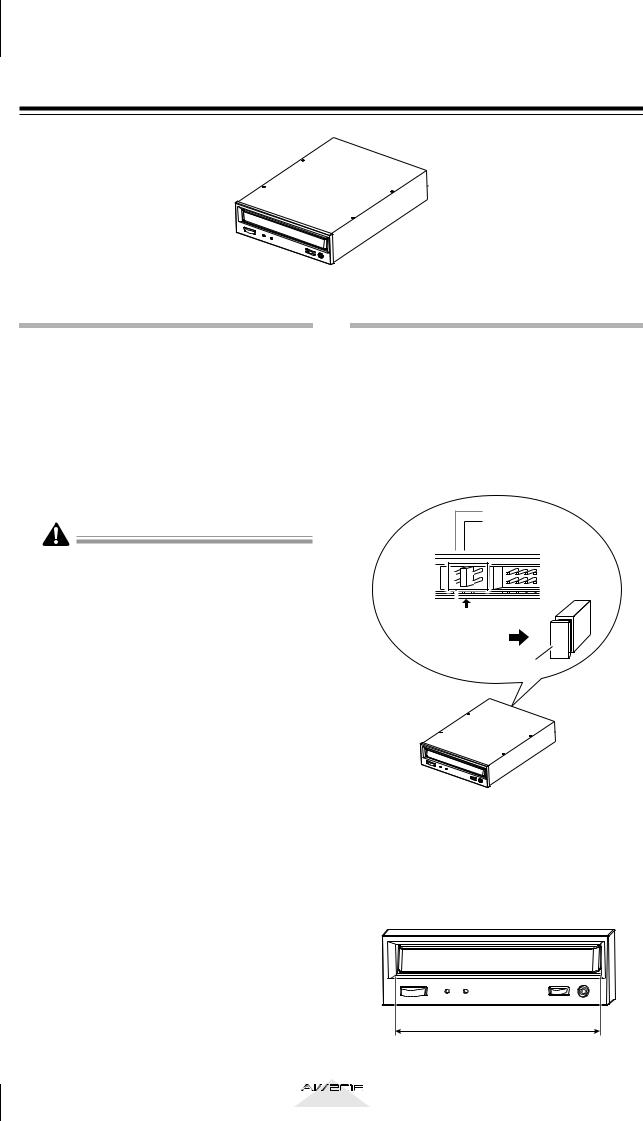
Insert the jumper (included with the CD-RW drive) into the jumper switch on the rear panel of the CDRW drive to set your CD-RW drive to function as a SLAVE unit. The AW2816 will not start up if the CDRW is set to a mode other than SLAVE.
•If you are installing a CD-RW drive manufactured by Yamaha, it will be set to SLAVE when shipped from the factory, so you do not need to change the setting.
CSEL
SLAVE
 MASTER
Set to SLAVE |
Jumper switch
Jumper
For details on this setting, refer to the manual that came with your CD-RW drive.
* Note that the cover panel of the AW2816 cannot be attached to a CD-RW drive with a lid-type tray. The AW2816’s cover panel can be attached to a CD-RW drive with a tray of the following dimensions.
Maximum 138 mm
4 |
Operation section |
|

Installation procedure
Please carefully read the cautions for installing optional equipment given at the beginning of this manual.
1 You will need the following items.
• The AW2816 itself
• Internal CD-RW drive (option)
• Four screws (included with the AW2816) for attaching the CD-RW drive
• Philips (+) screwdriver
• Work surface
• In order to install the CD-RW drive you will need to turn the AW2816 on its back. Make sure that you have a sufficiently broad work surface.
• The AW2816 is shipped with four screws for attaching the 2.5 inch hard disk, and four screws for attaching the CD-RW drive, making a total of eight screws of the same type.
2 Make sure that the power of the AW2816 is turned off. For safety’s sake, disconnect the power cable from the AC outlet.
Always switch off the power for the main unit and all peripherals, unplug the power cord for the main unit from the outlet, then disconnect the cables connecting the main unit with the peripherals before starting installation work.
3 Spread a soft cloth over your work surface, and place magazines or books to support the four corners of the AW2816 so that the faders, keys, and other controllers on the top panel will not be damaged. Then turn the AW2816 face down.
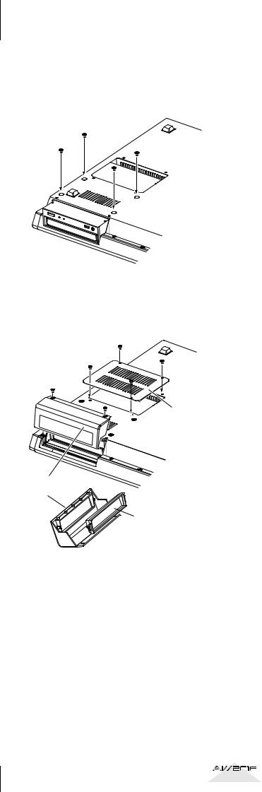
4 Remove the CD-RW drive cover from the front panel, and remove the bottom panel.
Bottom panel
CD-R/RW drive cover panel
5 Turn the CD-RW drive over, and insert it little by little, stopping when the connector end of the CD-RW drive enters the opening
in the bottom of the AW2816. Beforeyou
begin
6 Connect the flat cable (1) and CD-RW drive power supply connector (2) (from inside the AW2816) to the connectors of the CD-RW drive. Connect the flat cable first, and then the power supply connector.
Power supply connector
Flat cable
Operation section |
5 |
|
Before you begin
7 Align the fastening screw-holes on the bottom of the CD-RW drive with the screwholes in the AW2816, and using a screwdriver and the included screws, fasten it in four locations.
8 Re-attach the CD-RW drive cover and the bottom panel that you removed in step 4. At this time, remove the inner cover from the CD-RW drive cover.
Bottom panel
CD-R/RW drive cover panel
 Inner cover
6 |
Operation section |
|
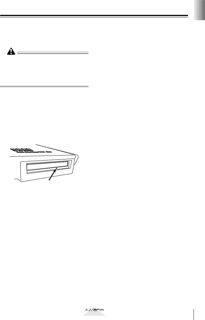
Removing the transport protection pad
The disc tray of some CD-RW drive models contains a transport protection pad that protects the internal mechanism from physical shock suffered during shipment. If your CD-RW drive contains this protective pad, please remove it before use.
Be sure to save the transport protection pad for the next time you need to transport the unit.
Manual eject (emergency disc removal)
Manual eject allows you to remove the disc manually in the case of an emergency such as a malfunction of the disc tray mechanism (usually temporary) or a power failure. Please be aware that using this method frequently can cause the CD-RW drive to malfunction. For the location of the eject hole and the procedure, refer to the manual of your CD-RW drive.
In order to perform this operation, you will need a pin-like object 2 mm or less in diameter, such as a straightened paper clip.
begin you Before
Eject Hall
Insert a pin-like object 2 mm or less in diameter.
*This diagram shows a CD-RW drive manufactured by Yamaha Corporation.
Operation section |
7 |
|
Before you begin
Attaching an external SCSI device
About external SCSI devices
The external SCSI devices referred to here are storage devices used to backup/restore the internal data of the AW2816, and can be connected to the SCSI connector on the rear panel of the AW2816. The following types of storage device can be used.
•Type of drive: MO drives (128 MB, 230 MB, 540MB, 640 MB 1.3 GB), hard disk drives, CDRW drives
•Interface: SCSI-2
•Models known to work: consult your local Yamaha distributor or refer to the website at the following URL.
<http://www.aw2816.com/>
•By “models known to work,” we mean commercially available models that Yamaha has obtained, connected to the AW2816, and successfully tested by means of various operational tests. However, we cannot take into account slight differences in performance that may occur due to the manufacturing tolerances of each manufacturer.
•Please be aware that Yamaha Corporation will accept no responsibility for any damages, neither direct nor indirect, resulting from the use of any of the above storage devices.
It is not possible to directly record or play back audio signals in realtime on an external storage device connected to the SCSI connector.
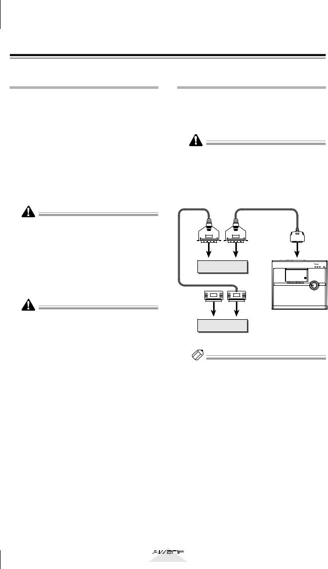
Connection procedure
1 Make sure that the power is turned off for the AW2816 and for the external SCSI device(s), and use a SCSI cable to connect the SCSI connectors of each device.
Use only good-quality SCSI cables.
When connecting an external SCSI device, use only high impedance SCSI cables of 100 ohms (±10 ohms) impedance that are 1 meter or shorter in length.
SCSI |
SCSI |
SCSI |
connector |
connector |
connector |
External SCSI device 1 |
|
|
Terminator |
|
AW2816 |
|
ID=6 (fixed) |
|
|
|
|
SCSI |
SCSI |
|
connector |
connector |
|
External SCSI device 2
Note
• A maximum of seven SCSI devices (SCSI ID= 0–5,7) can be connected in a daisy-chain.
• When connecting multiple SCSI devices, you must make sure that the SCSI ID of each device does not conflict with any other device. (For details on how to set the SCSI ID, refer to the manuals for your SCSI devices.)
• The SCSI ID of the AW2816 itself is fixed at “6.”
8 |
Operation section |
|

2 Attach a terminator to the last SCSI device in the chain.
A “terminator” is a device that terminates the SCSI signal at the end of the chain, and is normally attached to the vacant SCSI connector of the last device in the daisy chain. If the SCSI device itself has a built-in terminator, turn it on. (For details on how to turn on the internal terminator, refer to the manual of your SCSI device.)
Before using an external SCSI device, you will need to format it. For details on this procedure, refer to
page 160.
■ About terminators
“Termination” refers to the process of applying a resistor appropriate for the impedance of the SCSI bus to terminate the end of the circuit. The resistor required for this is called the “terminator.” Normally, a terminator must be installed at the beginning and end of the SCSI bus (in the case of the example in the previous page, this would be the AW2816 itself, and the SCSI device connected to the end of the daisy chain).
However, this is only a general principle, and is not an absolute. Depending on the combination of SCSI devices, the order of connection, or on the length of the SCSI cables, there may be cases in which better results are obtained by terminating only one end of the chain. If problems occur such as the AW2816 failing to start up when an external SCSI device is connected, try defeating the terminator of the external SCSI device. (The terminator inside the AW2816 is always on, and cannot be defeated.)
■ About SCSI errors
The SCSI bus is able to transfer data in a stable manner only if all connected SCSI devices are operating correctly. If the SCSI bus of the AW2816 is connected to a device whose operation is unstable or which produces noise, errors may occur in other devices, or the AW2816 may fail to start up correctly. If such problems occur, check the following points.
●Check the SCSI ID
Make sure that the SCSI ID of each SCSI device (including the AW2816) does not conflict with the SCSI ID of any other device. The SCSI ID of the AW2816 is fixed at “6.”
●Check the terminator
Check the location of the terminator. Under certain conditions, better results may be obtained by terminating only one end of the SCSI chain.
●Check the SCSI cables
Since errors are often caused by low-quality SCSI cables or unnecessarily long SCSI cables, you should avoid using such cables. Please use doubleshielded cables that are as short as possible. It is also important that the shield within the cable is grounded to the connector.
●External SCSI devices with 25-pin connectors
Most SCSI cables with 25-pin connectors at both ends do not meet SCSI specifications. For this reason if the system includes a SCSI device that uses a 25-pin connector, the problems may be due to this type of cable.
●Daisy-chain connection
Sometimes the operation of a SCSI bus will be unstable because of daisy-chain connections. Connect only the SCSI device you are using to the AW2816.
●Power supply of SCSI devices
When using the system, turn on the power of all connected SCSI devices. Operation of the SCSI bus cannot be guaranteed if one of the connected devices is not turned on.
begin you Before
Operation section |
9 |
|
Before you begin
Installing I/O card
About I/O cards
I/O cards compatible with the Yamaha mini-YGDAI format can be installed in the OPTION I/O slot located on the rear panel of the AW2816 in order to add input/output ports. For example by installing an ADAT format compatible I/O card into an OPTION I/ O slot, you can transmit/receive eight channels of digital audio to/from an ADAT format digital recorder.
At present, the following types of I/O cards can be used.
●MY8-AT
This card transmits and receives eight channels of Alesis ADAT format digital signals.
●MY8-TD
This card transmits and receives eight channels of TASCAM format digital signals.
●MY8-AE
This card transmits and receives eight channels of AES/EBU format digital signals.
●MY8-AD
This is an A/D card with eight channels of analog input jacks (balanced TRS phone jacks).
●MY4-AD
This is an A/D card with four channels of analog input jacks (balanced XLR jacks).
●MY4-DA
This is a D/A card with four channels of analog output jacks (balanced XLR jacks).
For up-to-date information on available MY cards, contact your local Yamaha distributor or check the following website.
<http://www.aw2816.com/>
Installation procedure
Please carefully read the cautions for installing optional devices, given at the beginning of this manual.
1 Make sure that the power of the AW2816 is turned off. For safety’s sake, disconnect the power cable from the AC outlet.
Always switch off the power for the main unit and all peripherals, unplug the power cord for the main unit from the outlet, then disconnect the cables connecting the main unit with the peripherals before starting installation work.
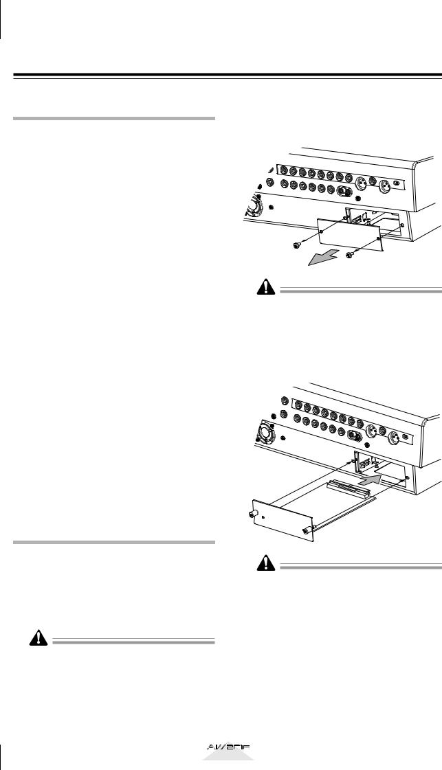
2 From the OPTION I/O slot located on the rear panel of the AW2816, remove the two screws that hold the cover in place.
Please keep the cover and screws you removed in a safe place.
3 Slide the I/O card along the rails inside the slot until it clicks into place.
4 Tighten the two screws included with the I/O card to fasten the card securely.
Please note that if the screws are loose, the card may not be grounded correctly.
10 |
Operation section |
|
Please observe the following points
This section explains how to turn the power of the AW2816 on and off, and how to set the internal clock.
Turning the power on
When turning on the power of a system that includes the AW2816, each device must be turned on in the following order.
1Any storage devices connected to the SCSI connector of the AW2816, and external tone generators connected to the input/output jacks
B The AW2816 itself
CThe monitor system connected to the output jacks or the AW2816
Following the opening screen, the following screen will appear in the display of the AW2816.
•If the AW2816 is powered-on when a SCSI-con- nected external device is turned off, it may not start up correctly.
•Do not turn off the power of a SCSI-connected device while the AW2816 is in use.
•Before turning the power on, check that the power cable plug is firmly connected to the AW2816 and to the AC outlet. If the power is accidentally disconnected (turned off) while the AW2816 is in use, the AW2816 itself and/or the hard disk may be damaged.
The first time the power is turned on after a new internal hard disk is installed in the AW2816, the display will indicate “Format OK? [Y (Enter)/N (Any)].” If you press the [ENTER] key at this time, the hard disk will be formatted automatically, and the screen shown above will appear when formatting has been completed.
Never turn off the power of the AW2816 while formatting is in progress. Doing so may damage the hard disk itself.
Setting the internal clock
When the AW2816 is shipped from the factory, the internal clock is set to Japan time. When you save a song you created on the AW2816, the date and time will be stored according to this internal clock.
Use the following procedure to set the date and time of the internal clock after replacing the internal battery, or if you need to set the clock for any other reason.
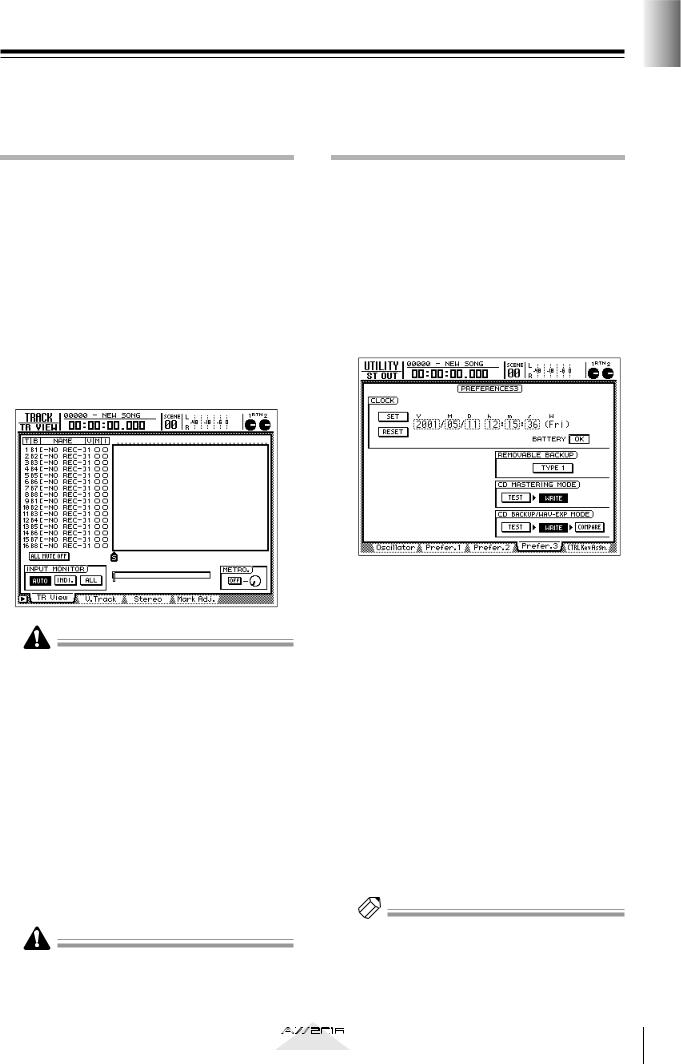
1 Press the [UTILITY] key → [F4] key.
The following screen will appear.
2 Use the CURSOR [ ] key to move the cursor (the blinking area in the display) to the Y (year) field in the CLOCK area, and turn the [DATA/JOG] dial to set the year.
The clock field will begin blinking.
3 In the same way, input the M (month), D (date), h (hour), m (minute), and s (second) fields.
The W (weekday) field will be set automatically according to the date.
4 When you have input all of the values, use the CURSOR keys to move the cursor to the SET button, and press the [ENTER] key.
The CLOCK area will stop blinking, and the new date and time will take effect. If you decide not to change the date and time, move the cursor to the RESET button and press the [ENTER] key.
Tip!
The internal clock continues to operate even when the power of the AW2816 is turned off. Once you have set the clock, you will not need to reset it unless you change the battery.
begin you Before
Operation section |
11 |
|
Before you begin
Turning the power off
When turning off the power of a system that includes the AW2816, each device must be turned off in the following order.
1The monitor system connected to the output jacks or the AW2816
B The AW2816 itself
CAny storage devices connected to the SCSI connector of the AW2816, and external tone generators connected to the input/output jacks
When turning off the power of the AW2816 itself, you must use the shutdown procedure described below.
1 In the WORK NAVIGATE section located on the top panel of the AW2816, press the [SONG] key.
2
3
Press the [F5] (SHUT DOWN) key located below the display.
Press the [ENTER] key.
A message will ask you whether you want to save the current song.
4 Use the CURSOR keys located in the right center of the top panel to move the cursor to the OK button, and press the [ENTER] key.
5 When a message of “Now safe to turn off” appears, turn off the [POWER] switch of the rear panel.
•If you turn off the power of the AW2816 without using the above shutdown procedure, the data on the hard disk may be damaged.
•Never turn off the power while the access indicator which indicates the access status of the internal hard disk is lit. Doing so may damage the hard disk itself.
12 |
Operation section |
|
Chapter
1 Parts and their functions
This chapter explains the functions of each part of the AW2816’s top panel, rear panel, and front panel.
The names of controllers (keys and knobs etc.) on the top panel are enclosed in square brackets [ ] in order to distinguish them from the software knobs and buttons that appear in the display. Example: [SEL] key, [GAIN] control
Top panel
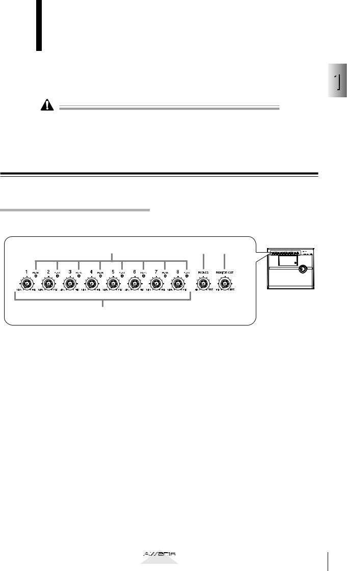
Analog input/output section
2 |
3 |
4 |
1
A[GAIN] control
These knobs adjust the input sensitivity of INPUT jacks 1–8 over a range of +4 dB to –46 dB. They support signals ranging from line level devices such as synthesizers to mic inputs.
B[PEAK] indicators
A [PEAK] indicator will light red if the input signal that has passed through the [GAIN] control reaches a level 3 dB below the clipping point. In order to record at the optimal level, adjust the [GAIN] control (1) so that this indicator flickers briefly when you play most loudly.
C[PHONES] (headphones) control
This knob adjusts the volume of the headphones connected to the rear panel PHONES jack.
D[MONITOR OUT] control
This knob adjusts the level of the signal that is output from the rear panel MONITOR OUT jacks.
1
functions their and Parts
Operation section |
13 |
|
Chapter |
Parts and their functions |
|
1
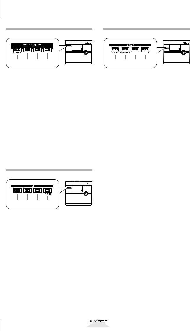
WORK NAVIGATE section
1 2 3 4
A[SONG] key
This key accesses the SONG screen, where you can save or load songs, or shut down the AW2816.
B[FILE] key
This key accesses the FILE screen, where you can backup and restore songs, and format or erase an internal/external drive.
C[CD] key
This key accesses the CD screen, where you can use an optional CD-RW drive to create an audio CD, or play back an audio CD.
D[QUICK REC] (Quick Record) key
This key accesses the QUICK REC screen, where you can instantly patch input signals to tracks.
UNIT section
1 2 3 4
A[SETUP] key
This key accesses the SETUP screen, where you can make basic settings for the AW2816 such as word clock, dither, and solo.
B[UTILITY] key
This key accesses the UTILITY screen, where you can operate the test tone oscillator, and make settings for the operating environment of the AW2816.
C[MID] key
This key accesses the MIDI screen, where you can make MIDI-related settings.
D[PATCH] key
This key accesses the PATCH screen, where you can patch external inputs/outputs to internal signal routes.
MIXER section
EQ/ATT/GRP DYN/DLY/
1 2 3 4
A[VIEW] key
This key accesses the VIEW screen, where you can view all mix parameters for a specified channel.
B[PAN] key
This key accesses the PAN/ROUTE screen, where you can set pan and routing for each channel.
CEQ (Equalizer) key
This key accesses the EQ/ATT/GRP screen, where you can set the EQ and attenuator of each channel, and make fader group and mute group settings.
D[DYN] (Dynamics) key
This key accesses the DYN/DLY screen, where you can make dynamics processor settings for a selected channel, and set the delay and phase of each channel.
14 |
Operation section |
|
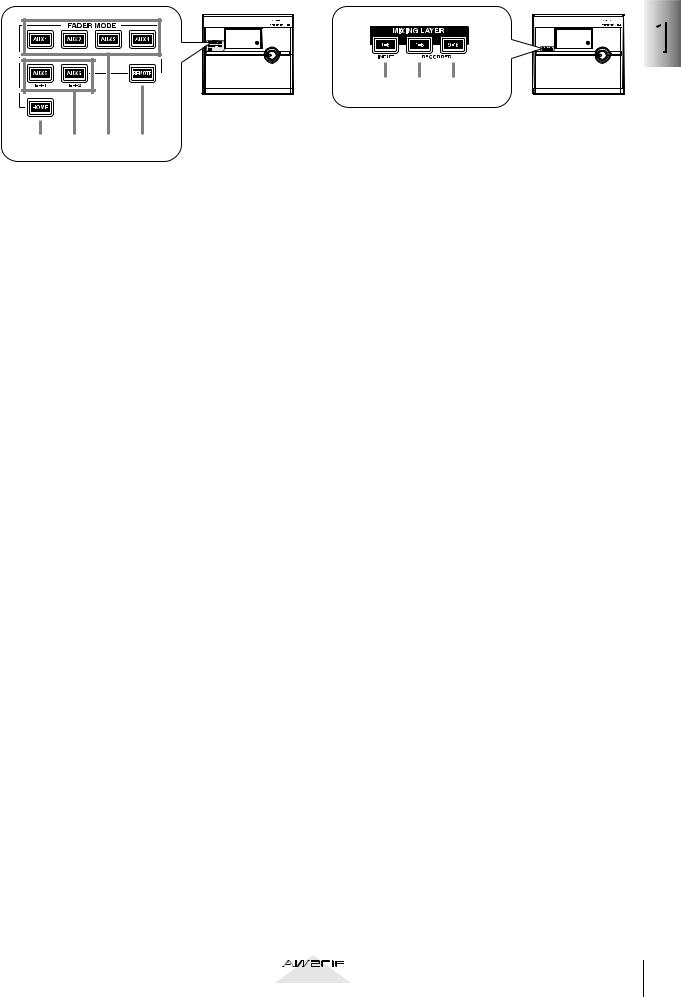
FADER MODE section |
MIXING LAYER section |
|
|
|
|
1 |
2 |
3 |
4 |
This section selects the parameters that will be controlled by the top panel faders 1–8. The selected key will light.
A[HOME] key
When this key is on, you can use faders 1–8 to control the input levels of the channels currently selected in the MIXING LAYER section. The display will show the HOME screen, where you can view meters that indicate the input/output levels of each channel.
B[AUX 5]/[AUX 6] keys
When these keys are on, you can use faders 1–8 to adjust the send levels of the signals sent to internal effects 1/2 from the channels currently selected in the MIXING LAYER section. The display will show the AUX5/EFF1 screen or AUX6/EFF2 screen, where you can make on/off and pre/post settings for the signals sent from each channel to internal effects 1/2, and set effect parameters.
C[AUX 1]–[AUX 4] keys
When this key is on, you can use faders 1–8 to control the send levels of the signals sent to AUX buses 1–4 from the channels selected in the MIXING LAYER section. The display will show the AUX 1–AUX 4 screens, where you can make on/ off and pre/post settings for the signals sent from each channel to AUX 1–4.
D[REMOTE] key
When this key is on, you can use faders 1–8 and [ON] keys 1–8 to remotely control external MIDI devices. The display will show the REMOTE screen, where you can make settings related to remote control.
1 2 3
AINPUT [1-8] key
BRECORDER [1-8] key
CRECORDER [9-16] key
These keys select the channels (mixing layer) that will be operated by [SEL] keys 1–8, [ON] keys 1– 8, and faders 1–8.
The currently selected key will light. When the respective key is selected, the [SEL] keys 1–8, [ON] keys 1–8, and faders 1–8 will operate the mixing layers listed below.
●When the INPUT [1-8] key is lit
Input channels 1–8
●When the RECORDER [1-8] key is lit
Monitor channels 1–8
●When the RECORDER [9-16] key is lit
Monitor channels 9–16
For details on channels and mixing layers, refer to page 38.
1
functions their and Parts
Operation section |
15 |
|

Chapter
1
Parts and their functions
Fader section
1 |
|
2 |
|
4 |
5 |
3 |
|
A[SEL] keys (1–8/STEREO/RTN 1/RTN 2) |
|
These keys select the channel for operation.
B[ON] keys (1–8/STEREO/RTN 1/RTN 2)
These keys turn each channel on/off.
CFaders (1–8/STEREO)
According to the settings of the FADER MODE section and MIXING LAYER section, these moving faders adjust either the input level of each channel or the send level of each channel to AUX buses 1– 6.
D[RTN 1]/[RTN 2] controls
According to the settings of the FADER MODE section, these knobs adjust either the level of return channels 1/2 (effect return) or the send level from return channels 1/2 to AUX buses 1–6.
Return channel 1 does not have a send level to AUX bus 5. Similarly, return channel 2 does not have a send level to AUX bus 6.
E[SOLO] key (1–16/STEREO/RTN 1/RTN 2)
This key switches the Solo function on/off.
16 |
Operation section |
|
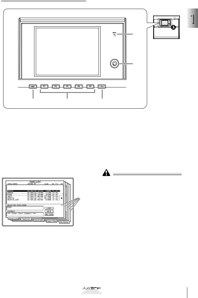
Display section
6
1
5
1
functions their and Parts
2 |
3 |
4 |
ADisplay
This is a 320 x 240 pixel liquid crystal display with backlight, that displays the mix parameter settings and the current operating status.
When you press one of the keys in the WORK NAVIGATE or UNIT section, the screen for the corresponding key will appear. Most screens consist of multiple “pages” (the name of the pages in each screen are indicated by tabs at the bottom of the screen), and you can use the [F1]–[F5] keys (3) to access the desired page.
Screen
pages
D[CTRL] (Control) key
This key is used in conjunction with the function keys (3) to execute user-defined functions.
EContrast
This knob adjusts the brightness of the display.
FAccess indicator
This indicator indicates the access status of the internal hard disk. When the hard disk is being read or written, this indicator will light.
Never turn off the power of the AW2816 when the access indicator is lit. Doing so will not only damage the data on the internal hard disk, but may also damage the hard disk itself. When you want to turn off the power of the AW2816, you must perform the shutdown procedure (→P.12).
B[SHIFT] key
This key is used in conjunction with the function keys (3) to execute additional functions.
C[F1]–[F5] (Function 1–5) keys
These keys select pages within the currently selected screen. When the [SHIFT] key or [CTRL] key is held down, these keys execute additional functions assigned to each key.
Operation section |
17 |
|
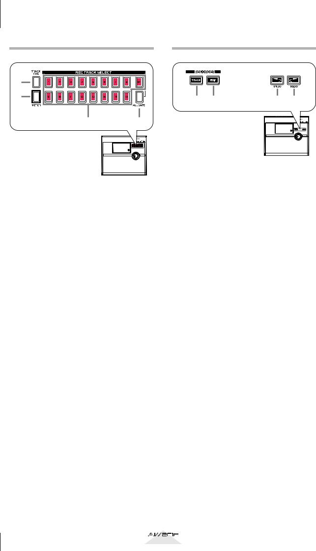
Chapter |
Parts and their functions |
|
1
REC TRACK SELECT section
1 |
2 |
3 4
A[CUE] key
This key allows the output of tracks 1–16 or the stereo track to be monitored directly from the MONITOR OUT jacks without passing through the monitor channel.
Use the REC TRACK SELECT keys (3) to select a track. When you press the [CUE] key, the [CUE] key and the REC TRACK SELECT keys will blink, allowing you to select a track. Press a REC TRACK SELECT key to select a track, and that key will light.
B[METER] key
This key accesses the METER screen, where you can view meters of the input/output level of tracks 1–16 and the output level of the stereo output channel.
CREC TRACK SELECT [1]–[16]/[ST]
These keys select the recording track (tracks 1–16 or the stereo track).
D[ALL SAFE] key
This key cancels record-ready mode for all tracks. If any tracks are muted, all muting will be cancelled.
RECORDER section
1 |
2 |
3 |
4 |
A[TRACK] key
This key accesses the TRACK screen, where you can operate the audio tracks of the recorder section.
B[EDIT] key
This key accesses the EDIT screen, where you can edit the audio tracks that have been recorded.
C[UNDO] key
This key cancels the most recently performed recording or editing operation, returning to the previous state (Undo). When the Undo function is available, the [UNDO] key will light.
D[REDO] key
This key re-executes the recording or editing operation that was cancelled by the [UNDO] key (Redo). When the Redo function is available, the [REDO] key will light.
18 |
Operation section |
|
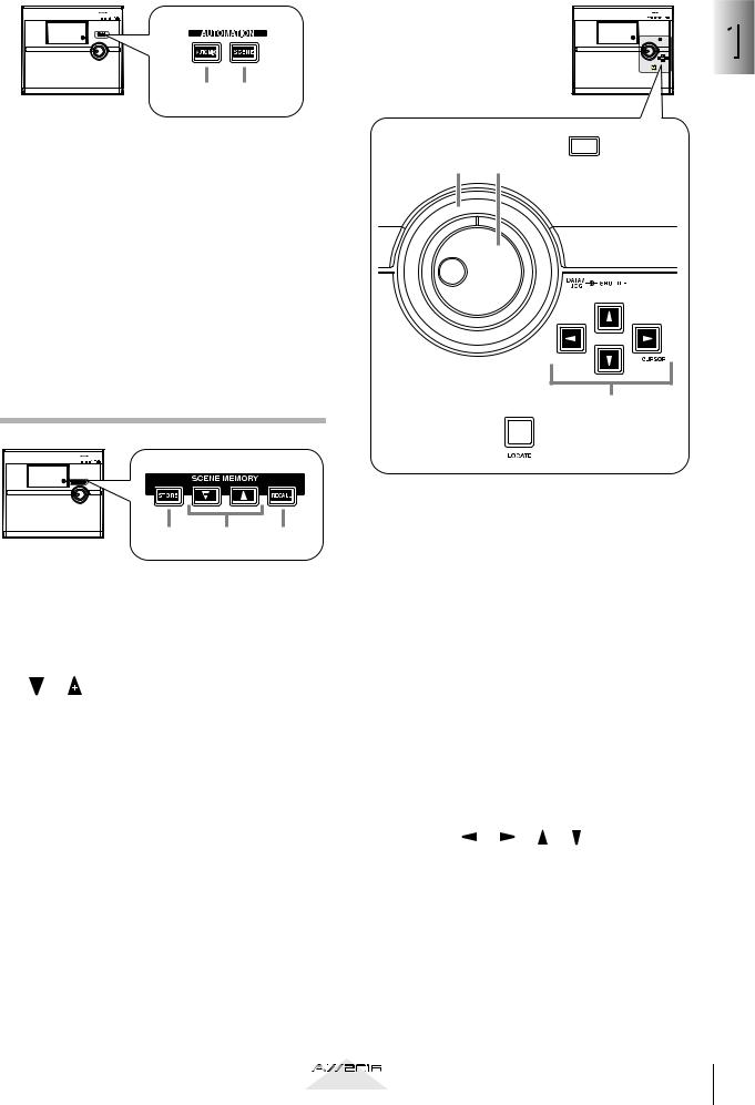
AUTOMATION section |
CURSOR/JOG&SHUTTLE section |
|||||
|
|
|
|
|
|
|
|
|
|
|
|
|
|
1 2

 1
1
A[AUTOMIX] key |
3 2 |
This key accesses the AUTOMIX screen, where you can perform automix operations. By using automix, operations of mix parameters such as the faders and [ON] keys can be recorded in realtime.
B[SCENE] key
This key accesses the SCENE screen, where you can perform scene memory operations. By using scene memories, you can save the current state of the mixer section and the input/output patching state.
1
functions their and Parts
SCENE MEMORY section
1 2 3
A[STORE] key
This key saves the current state of the mixer section and input/output patching to the scene number shown in the display.
B[ ]/[ ] keys
These keys select the store destination or recall source scene number.
C[RECALL] key
This key recalls the scene number currently shown in the display.
4
5

A[JOG ON] key
This key is an on/off switch for the Nudge function (a destination that repeatedly plays a specified region before or after the current location) controlled by the [DATA/JOG], [SHUTTLE] dial. When the Nudge function is on, the [JOG ON] key will light.
B[DATA/JOG] dial
Depending on the on/off status of the [JOG ON] key and the [NUM LOCATE] key of the Locate section, this dial is used to edit parameter values or to operate the Nudge function.
C[SHUTTLE] dial
Depending on the on/off status of the [JOG ON] key, this dial rewinds or fast-forwards the playback (review or cue), or operates the Nudge function.
DCURSOR [ ]/[ ]/[ ]/[ ] keys
These keys are used to move the cursor (the blinking box) in the display.
E[ENTER] key
This key is used to operate a button displayed in the screen, to finalize a numerical value that you input, or to execute a specific function.
Operation section |
19 |
|
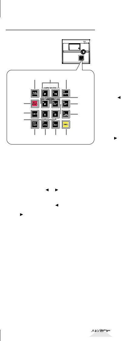
Chapter |
Parts and their functions |
|
1
LOCATE section
1 2 3
|
5 |
4 |
6 |
7 |
9 |
|
|
8 |
|
J K L M
A[NUM LOCATE] key
This key is used to specify a location numerically. When this key is lit, you can use the numeric keys or the [DATA/JOG] dial to input a location, and press the [ENTER] key to execute the locate operation.
BMARK SEARCH [  ]/[
]/[  ] keys
These keys are used to search for markers placed in a song. If a marker has been placed earlier than the current location, the [  ] key will light. If a marker has been placed after the current location, the [
  ] key will light.
C[MARK] key
This key sets a marker at the current location of the song.
D[AUTO PUNCH] key
This key turns the auto punch-in/out function on/ off.
ELAST REC [IN/[OUT] (Last recording in/ out) key
These keys set the recording start location (In point) and end location (Out point) for auto punch-in/out. When these keys are lit, you can use them as locate keys to move to the point at which recording most recently began (In point) or ended (Out point).
F[SET] key
This key is used in conjunction with the LAST REC [IN]/[OUT] keys or the [A]/[B] keys to set the current location of the song to a locate point.
G[REPEAT] key
This key is an on/off switch for the A-B Repeat function which repeatedly plays a specified region.
H[A]/[B] keys
These keys set the beginning (A point) and end (B point) of the region played by the A-B Repeat function. These keys can also be used as locate keys to specify the A point or B point as locate destinations.
I[ROLL BACK] key
This key rewinds the current location by a specified distance.
J[ ] key
] key
This key locates to the absolute time zero location (start point).
K[RTZ] (Return to zero) key
This key locates to the counter zero location (when the counter is displaying measures, this will be the beginning of the first measure).
L[  ] key
] key
This key locates to the last location at which audio is recorded (end point).
M[CANCEL] key
In conjunction with the LAST REC [IN]/[OUT] keys, [A]/[B] keys, and [MARK] keys, this key erases a locate point from the song.
20 |
Operation section |
|

Transport section
1 2 3 4 5
AREW [ ] (Rewind) key
This key rewinds from the current location. Each time you press this key, you will switch between 8X speed and 16X speed rewinding. To stop rewinding, press the STOP [  ] key or PLAY [ ] key.
BFF [ ] (Fast-forward) key
This key fast-forwards from the current location. Each time you press this key, you will switch between 8X speed and 16X speed fast-forwarding. To stop fast-forwarding, press the STOP [  ] key or PLAY [ ] key.
CSTOP [  ] key
] key
This key stops playback, recording, fast-forward, or rewind.
DPLAY [ ] key
When the recorder is stopped, pressing this key will begin playback. (If you hold down the REC [ ] key and press this key, recording will begin.)
Pressing this key during rewind or fast-forward will switch to normal-speed playback.
Pressing this key during recording will stop recording and continue pressing (i.e., punch-out).
EREC [ ] (Record) key
When the recorder is stopped, holding down this key and pressing the PLAY[ ] key will begin recording.
During playback, holding down this key and pressing the PLAY [ ] key will switch from playback to recording (i.e., punch-in).
1
functions their and Parts
Operation section |
21 |
|
 Loading...