


02R
DIGITAL RECORDING CONSOLE
DIGITAL MIXING CONSOLE

Table of Contents
Introduction . . . . . . . . . . . . . . . . . . . . . . . . . . . . . . . . . . . . . . 1
Equipment in this Guide . . . . . . . . . . . . . . . . . . . . . . . . . . . . . 1
Part 1: 02R Applications . . . . . . . . . . . . . . . . . . . . 5
System Operating Notes . . . . . . . . . . . . . . . . . . . . . . . . . . . . . . . . . 5
02R Optional Interface Cards. . . . . . . . . . . . . . . . . . . . . . . . . . . . . . 7
Wordclock Connection and Termination . . . . . . . . . . . . . . . . . . . . . 8
Wordclocks . . . . . . . . . . . . . . . . . . . . . . . . . . . . . . . . . . . . . . . . . . . 9
Setting the 02R’s Wordclock . . . . . . . . . . . . . . . . . . . . . . . . . . . . . . 9
1. 02R with One ADAT (Timecode on Tape Track) . . . . . . . . . 12
2. 02R with ADAT & JL Cooper Datasync-2 . . . . . . . . . . . . . . . 14
3. 02R with Two ADATs & JL Cooper Datasync-2. . . . . . . . . . . 16
4. 02R with ADAT & BRC. . . . . . . . . . . . . . . . . . . . . . . . . . . . . . 18
5. 02R with Two ADATs & BRC . . . . . . . . . . . . . . . . . . . . . . . . . 20
6. Two 02Rs with Four ADATs & BRC . . . . . . . . . . . . . . . . . . . . 22
7. 02R with Two ADATs (Timecode on Tape Track). . . . . . . . . 24
8. 02R with ADAT & RD-8 . . . . . . . . . . . . . . . . . . . . . . . . . . . . . 26
9. 02R with One DA-88 . . . . . . . . . . . . . . . . . . . . . . . . . . . . . . . 28
10. 02R with Two DA-88s . . . . . . . . . . . . . . . . . . . . . . . . . . . . . . 30
11. 02R with Four DA-88s . . . . . . . . . . . . . . . . . . . . . . . . . . . . . . 32
12. Two 02Rs with Four DA-88s . . . . . . . . . . . . . . . . . . . . . . . . . 34
13. 02R with Akai DR8 Hard Disk Recorder . . . . . . . . . . . . . . . . 36
14. 02R with Akai DR16 Hard Disk Recorder . . . . . . . . . . . . . . . 38
15. 02R with Analog 16-Track Multitrack Recorder . . . . . . . . . . 40
16. 02R with Video Machine, ADAT, & BRC . . . . . . . . . . . . . . . . 42
17. 02R with Video Machine, ADAT, & AI-2 . . . . . . . . . . . . . . . . 44
18. 02R with Video Machine & DA-88 . . . . . . . . . . . . . . . . . . . . 46
19. 02R with Two Fostex D-90s . . . . . . . . . . . . . . . . . . . . . . . . . 48
20. 02R with Pro Tools for Music Recording . . . . . . . . . . . . . . . 50
21. 02R with Pro Tools for Video Post . . . . . . . . . . . . . . . . . . . . 52
Yamaha 02R & 03D Applications Guide

Part 2: 03D Applications. . . . . . . . . . . . . . . . . . . . 57
System Operating Notes . . . . . . . . . . . . . . . . . . . . . . . . . . . . . . . . . 57
03D Optional Interface Cards . . . . . . . . . . . . . . . . . . . . . . . . . . . . . 58
Wordclock Connections & Termination . . . . . . . . . . . . . . . . . . . . . . 59
Wordclocks . . . . . . . . . . . . . . . . . . . . . . . . . . . . . . . . . . . . . . . . . . . 60
Setting the 03D’s Wordclock . . . . . . . . . . . . . . . . . . . . . . . . . . . . . . 60
22. 03D with ADAT & JL Cooper Datasync-2 . . . . . . . . . . . . . . . 62
23. 03D with DA-38 (Timecode on Tape Track). . . . . . . . . . . . . 64
24. 03D with Akai DR8 . . . . . . . . . . . . . . . . . . . . . . . . . . . . . . . . 66
25. 03D with Akai DR16 . . . . . . . . . . . . . . . . . . . . . . . . . . . . . . . 68
26. 03D with Fostex D-90 . . . . . . . . . . . . . . . . . . . . . . . . . . . . . . 70
27. 03D with Syncman Plus & Analog Multitrack . . . . . . . . . . . 72
28. 03D with Video Machine & DA-88 . . . . . . . . . . . . . . . . . . . . 74
29. 03D with Pro Tools . . . . . . . . . . . . . . . . . . . . . . . . . . . . . . . . 76
30. 03D Basic MIDI Studio . . . . . . . . . . . . . . . . . . . . . . . . . . . . . 78
31. 03D Installation. . . . . . . . . . . . . . . . . . . . . . . . . . . . . . . . . . . 80
Yamaha 02R & 03D Applications Guide

Trademarks
ADAT and Alesis are registered trademarks of Alesis Corporation.
ADAT MultiChannel Optical Digital Interface is a trademark of Alesis Corporation.
Akai is a trademark of Akai Electric Corporation.
Digidesign is a trademark of Digidesign or Avid Technology, Inc.
Fostex is a trademark of Fostex Corporation.
Mark of the Unicorn is a trademark of Mark of the Unicorn, Inc.
Opcode is a trademark of Opcode Systems, Inc.
Pro Tools is a registered trademark of Digidesign or Avid Technology, Inc.
TASCAM and TEAC are registered trademarks of TEAC Corporation.
Tascam Digital Interface (TDIF-1) is a trademark of TEAC Corporation.
JL Cooper is a trademark of JL Cooper Electronics.
All other trademarks and registered trademarks are the property of their respective holders.
Copyright
© 1997 Yamaha Corporation. All rights reserved.
No part of this Applications Guide may be reproduced or distributed in any form or by any means without
the prior written authorization of Yamaha Corporation.
Yamaha 02R & 03D Applications Guide

Yamaha 02R & 03D Applications Guide

Introduction 1
Introduction
This Applications Guide provides detailed examples of real-life 02R and 03D recording
systems. The application diagrams show exactly what equipment is needed for each system
and how to connect and make the relevant settings. The 02R and 03D feature as the main
components throughout the applications, with various equipment by other manufacturers
introduced to form complete systems.
Equipment in this Guide
The applications in this guide show how the 02R and 03D can be used with complementary
equipment from other manufacturers to create complete recording and mixing systems. For
those not familiar with 02R and 03D complementary equipment, here’s a brief description
of several such products.
Akai DR8 & DR16
The Akai DR8 is a digital hard disk recorder featuring 8-track simultaneous recording and
playback. The optional ADAT (IB-804A) interface card provides 8-channel digital I/O with
an 02R or 03D. The DR16 is a 16-track hard disk recorder featuring 8-track recording and
16-track playback. The optional ADAT (IB804AEX) interface card, for use only with the
DR16, provides 8 digital inputs and 16 digital outputs.
Alesis ADAT Professional Digital Audio Recorder
This is the original ADAT format recorder made by Alesis. It’s an eight-track recorder and
uses standard S-VHS tapes. It features 16-bit, 64-times oversampling AD/DA converters,
and a sampling rate of 48 kHz. A 120 minute S-VHS tape provides a total recording time of
40 minutes. Up to 16 ADATs can be connected together for a fully synchronized, sample
accurate 128 track recording system. Digital I/O consists of Alesis optical connectors. These
can be connected directly to an 02R or 03D with an optional CD8-AT Digital I/O card. The
LRC Remote Control, which duplicates the front panel controls, comes as standard, and a
full function BRC Master Remote Control is available as an option.
Alesis BRC Master Remote Control
The BRC Master Remote Control provides complete synchronized remote control of up to
16 ADATs, for 128-track recording. Sample accurate digital copy and paste editing allows
digital audio data to be transferred between ADATs with no signal degradation. In addition,
the BRC reads and writes SMPTE timecode, generates MIDI Timecode and MIDI clocks,
reads and generates wordclock, and reads composite video sync. Autolocation provides
multiple locate points per song. Seamless punch in/out is assisted with variable crossfade.
Alesis AI-2 Multipurpose Audio/Video Synchronization Interface
The Alesis AI-2 Multipurpose Audio/Video Synchronization Interface supports SMPTE
timecode, Sony 9-pin protocol, video sync, 44.1 kHz and 48 kHz sampling rates, and MIDI
Timecode. So ADATs can easily be slaved to video and audio master recorders. At the same
time, the AI-2 can provide timecode via its timecode output, which can be fed to the 02R for
use with automix.
Alesis M20
The Alesis M20 is a 20-bit, 8-track digital multitrack recorder. It can be connected to the
02R or 03D digital mixers, which both support a maximum wordlength of 24 bits, using
existing CD8-AT interface cards, which do not require modification or special settings.
Yamaha 02R & 03D Applications Guide

2 Introduction
Fostex D-90 8-track Digital Recorder
The Fostex D-90 is a digital hard disk recorder featuring 8-track simultaneous recording
and playback and ADAT I/O as standard.
Fostex RD-8 Digital Multitrack Recorder
The Fostex RD-8 Digital Multitrack Recorder uses the same eight-track digital format as the
Alesis ADAT, making it fully compatible. Digital I/O, Sync I/O, and meter bridge
connections are also compatible with those of the ADAT. The RD-8 can be connected
directly to an 02R or 03D with an optional CD8-AT Digital I/O card. The RD-8 features an
on-board synchronizer for synchronization to a master recorder via timecode. Timecode
offset and MIDI Machine Control are supported. LTC can be recorded on a dedicated
timecode track. There are 100 locate points and variable pre and post roll times. Essentially,
the RD-8 is an ADAT with some of the features of the BRC Master Remote Control and AI-2
Multipurpose Audio/Video Synchronization Interface on-board.
JL Cooper Datasync-2 Synchronizer
The JL Cooper Datasync-2 Synchronizer is a relatively low cost synchronizer that can be
used to convert ADAT format sync to SMPTE timecode and MTC. It can be used to set up
a cost-effective, fully synchronized 02R or 03D and ADAT digital recording system.
Midiman Syncman Plus
The Midiman Syncman Plus is an SMPTE to MTC converter and MTC generator. Front
panel DIP switches are used to select the timecode type when working as a generator. For
SMPTE to MTC conversion the frame rate is detected and set automatically.
TASCAM DA-88 & DA-38 Digital Multitrack Recorders
The TASCAM DA-88 Digital Multitrack Recorder is an eight-track digital recorder that uses
8 mm video tape and a 4-head mechanism. It features 16-bit AD/DA converters and
44.1 kHz and 48 kHz sampling rates. A 120 minute tape provides a recording time of 108
minutes. Up to 16 DA-88s can be connected together for a fully synchronized, sample
accurate 128-track recording system. Digital I/O consists of a TASCAM TDIF-1 connector.
This can be connected directly to an 02R or 03D with an optional CD8-TDII Digital I/O
card. The TASCAM DA-38 is a lower-cost Digital Multitrack Recorder aimed at musicians,
and provides full compatibility with tapes recorded on the DA-88.
TASCAM SY-88 Sync Board
The optional TASCAM SY-88 Sync Board provides versatile synchronization facilities for
the TASCAM DA-88. It features on-board SMPTE and MIDI timecode generators, an
RS422 video editor connection, and video sync inputs. An SY-88 Sync Board is essential for
synchronization with 02R or 03D automation.
In a multiple DA-88 system, only the Control Master DA-88 needs to have an SY-88 Sync
Board installed. Control slaves do not need SY-88 Sync Boards. Also, only the tape used in
the Control Master DA-88 needs to be striped with timecode.
TASCAM MMC-38 Interface Unit
The optional TASCAM MMC-38 Interface Unit provides versatile synchronization facilities
for the TASCAM DA-38. It features on-board SMPTE and MIDI timecode generators, and
is essential for synchronization with 02R or 03D automation.
Yamaha 02R & 03D Applications Guide
02R
DIGITAL RECORDING CONSOLE

02R Applications 5
Part 1: 02R Applications
System Operating Notes
02R
• 02R interface cards must be screwed securely in place. Do not leave the screws out after
installation as the cards will not be grounded correctly.
• If a crackling noise can be heard, make sure not more than one device is set to internal
wordclock. One device should be set for internal wordclock (master) and all other
devices should be set to external wordclock (slave).
• To see the version number of an 02R, hold down the UTILITY button while turning on
the 02R.
02R Cascade
02R
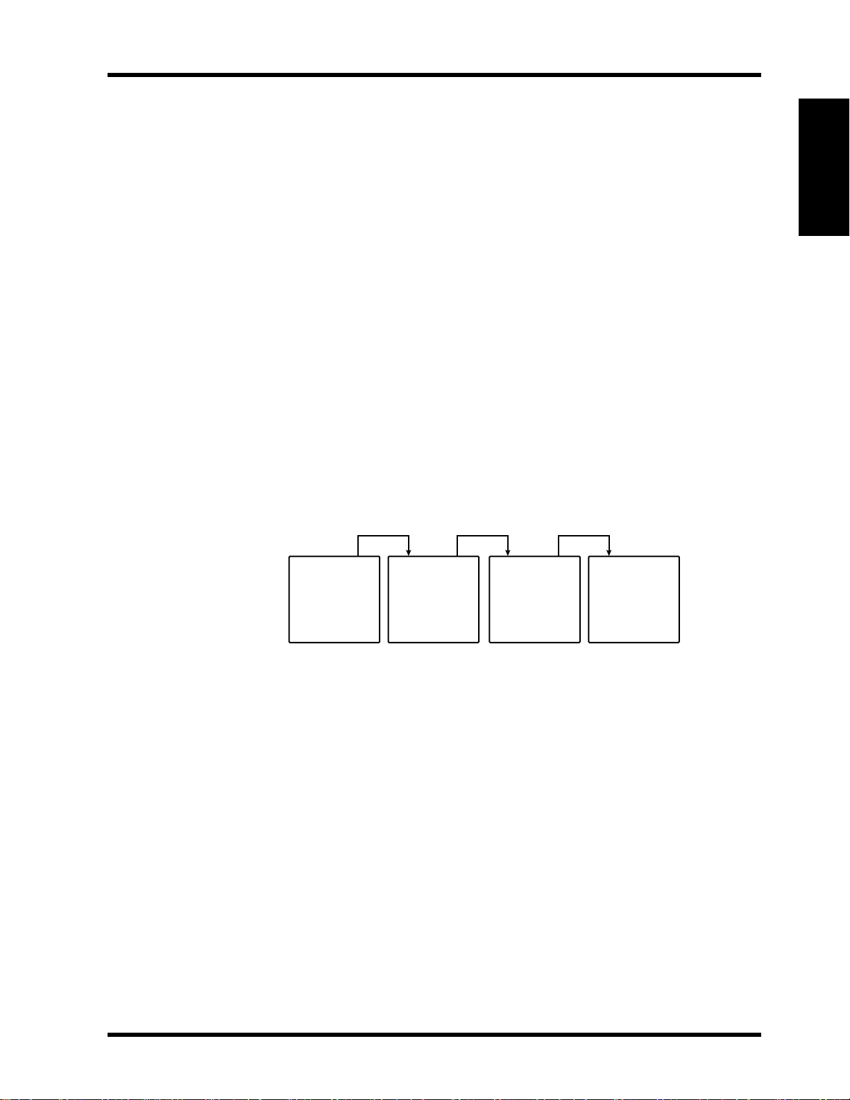
• In a cascaded 02R system, the ID parameter on the Cascade Configuration display must
be set correctly. The setting determines the amount of delay compensation. The ID
parameter is available only when a CD8-CS Cascade card is installed. The ID on the first
02R in a cascade system does not need to be set. In fact, because the IN/OUT switch on
the Cascade card in the first 02R is set to OUT, the ID parameter cannot be set. The next
02R should be set to ID 1, the next to ID 2, and the last to ID 3, as shown below.
ID=0
02R-A
• The CD8-CS Cascade kit contains two CD8-CS cards and one 25-pin straight cable.
ADAT
• To use the ADAT’s DIGITAL INPUT, press the DIGITAL IN button on the ADAT. Do not
press the DIGITAL I/O button on the BRC.
• Set the DIGITAL I/O button on the BRC to OFF. This function is for direct ping-pong
between multiple ADATs. If this is turned ON while connected to an 02R, bus
assignments will produce unexpected results. Press the DIGITAL IN button on the
ADAT to use the DIGITAL INPUT.
• To check the ADAT wordclock source, press the SET LOCATE and DIGITAL IN buttons
together. The display will show “int” for internal or “digi” for external.
• The sampling rate of an ADAT can be set to either 48 kHz or 44.1 kHz. Use Fixed mode
for 48 kHz and Variable mode for 44.1 kHz (using the PITCH DOWN button, set to
–146 cents. At which point 44.1 appears on the display). The newer ADAT-XT has
dedicated switches for selecting these two sampling rates.
ID=1
02R-B
ID=2
02R-C
ID=3
02R-D
Yamaha 02R & 03D Applications Guide

6 02R Applications
• In a multiple ADAT system with no BRC, Control Slave ADATs must be powered up
before the Control Master ADAT, because when the Control Master ADAT is powered up
it checks how many Control Slave ADATs are connected, allocates them device numbers,
and automatically sets the system wordclock.
• In an ADAT system with a BRC, the ADAT(s) must be powered up before the BRC,
because when the BRC is powered up it checks how many ADATs are connected, allocates
them device numbers, and automatically sets the system wordclock. The BRC works as
Control Master.
• To generate timecode on a BRC, press the GEN SYNC button.
• ADAT tapes can be duplicated when ADATs are connected together directly. Be aware
that a delay (27 samples) will be introduced if tapes are duplicated via the 02R.
• To see the version number of an ADAT, press the SET LOCATE and FAST FWD buttons
together.
• Both the ADAT and BRC can be initialized as follows. Initialization is recommended
when a BRC is behaving strangely, and the first time an ADAT is connected to a BRC. To
initialize, hold down the RECORD and PLAY transport buttons while turning on the
power.
DA-88
• In an 02R and DA-88 system, all connected DA-88s must be powered up even if they are
not being used. Failure to do so may cause an intermittent pumping noise on the 02R.
• The sampling rate and the use of Emphasis in a DA-88 system is determined when the
DA-88 tapes are formatted. For digital recording we recommend that Emphasis be OFF.
• In a single DA-88 system, the MACHINE ID is set to 0.
• In a multiple DA-88 system, the Control Master is set to MACHINE ID 0 and subsequent
DA-88 Control Slaves are set to MACHINE ID 1 and upwards. The Control Master
DA-88 should be used for synchronized transport and locate operations.
• The terminator bundled with the PW-88S sync cable should be connected to the SYNC
OUT connector on the last DA-88 in the chain to ensure reliable synchronization.
• The optional Tascam SY-88 Sync Board must be installed to use SMPTE timecode and
MTC. This is available from Tascam. In a multiple DA-88 system, only the Control
Master DA-88 needs to have an SY-88 Sync Board installed. Control Slaves do not need
SY-88 Sync Boards. Also, only the tape used in the DA-88 Control Master needs to be
striped with timecode.
• The rear panel of the SY-88 Sync Board has a DIP switch labeled MODE. Set DIP
switches 2 and 5 to ON (O). Set internal switch 8 on the SY-88 board marked S2 to ON.
• To use the MTC function, the SY-88
• Depending on the version of SY-88 Sync Board used, you may need to terminate the
WORDCLOCK IN connection when the DA-88 is used as a wordclock slave.
firmware
must be version 3.08 or higher.
• On the Tascam (CD8-TD) cards there is a DIP switch that should be set to 16-bit. This
is the initial setting, but you should confirm it. This switch is for use with Tascam
High-Bit recording applications.
• The Tascam 25-pin digital audio cables PW-88DL (5 m) and PW-88D (1 m) are
available from Tascam.
• DA-88 tapes can be duplicated when DA-88s are connected together directly. Be aware
that a delay (24 samples) will be introduced if tapes are duplicated via the 02R.
Yamaha 02R & 03D Applications Guide
02R Applications 7
• To see the version number of a DA-88, hold down the REW, F FWD, and STOP buttons
when powering up the DA-88.
Akai DR8 & DR16
• When a track is armed for recording, the DR8 or DR16 will normally try to take its
wordclock source from that track’s input. To prevent this, in the Digi submenu set Auto
Sync to Off. Note that the Auto Sync setting is not memorized when the DR8 or DR16 is
turned off, although it can be stored as part of a project.
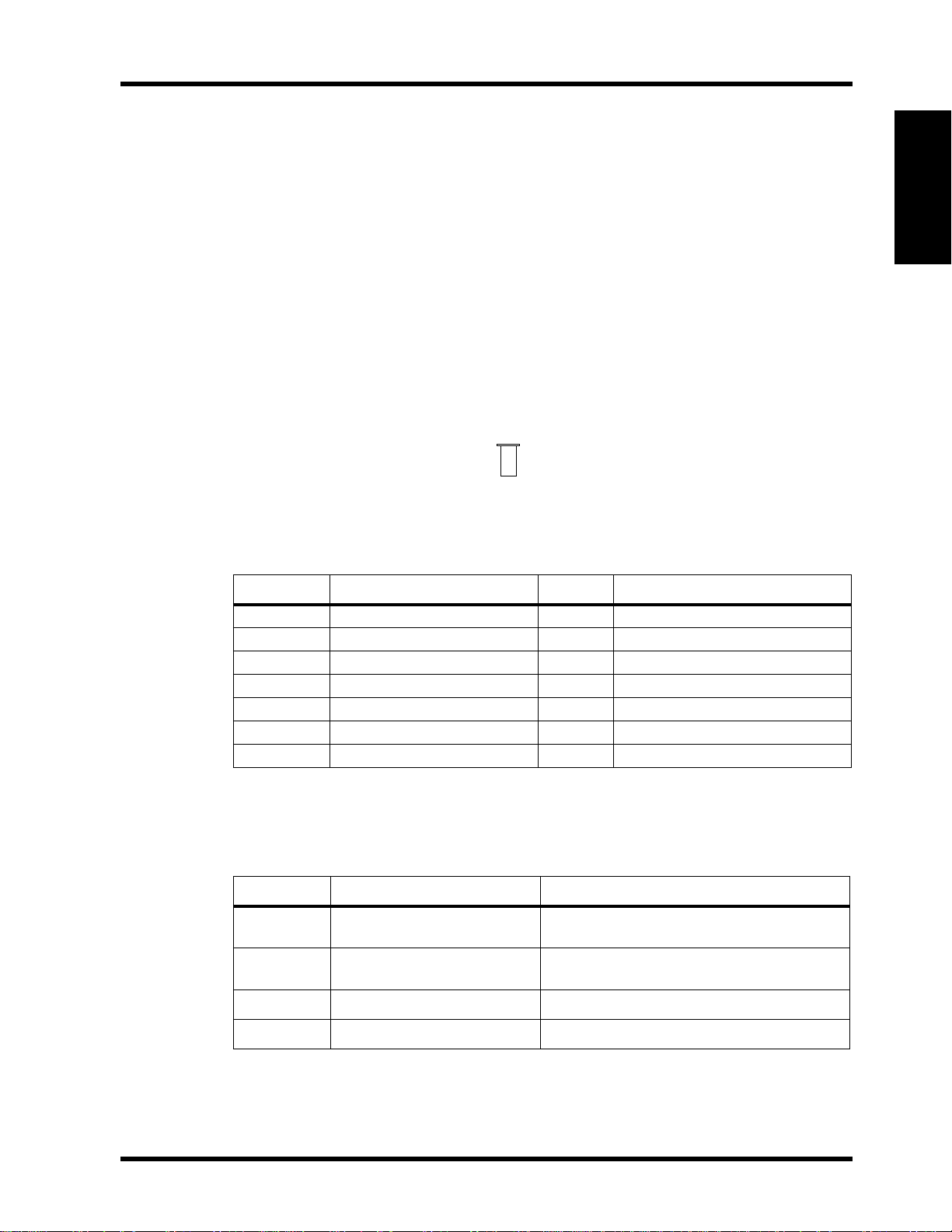
02R Optional Interface Cards
To interface the 02R with digital multitrack equipment, optional interface cards are
required. Up to four single-size interface cards can be installed in the 02R.
In the system diagrams presented in this guide, interface cards are numbered from [1] to
[4] . These numbers refer to the 02R slot in which the card is installed. The following
illustration shows an interface card that is installed in 02R slot [1] .
1
Available Cards
The following table lists the available interface cards.
Model Description Size Slots
CD8-AE Digital I/O Card (AES/EBU)
CD8-AE-S Digital I/O Card (AES/EBU)
CD8-AT Digital I/O Card (ADAT) Single
CD8-AD AD/DA Card Double
CD8-CS KIT Digital Cascade Kit Single Any (normally
CD8-TDII Digital I/O Card (TDIF-1) Single
CD8-Y Digital I/O Card (Yamaha) Single
a. Double size requires two slots.
b. Single size requires one slot.
a
Double
b
Single
[1]
[1]
[1]
[1]
[1]
[1]
[2]
–
(max 2 cards—16 ch)
–
(max 4 cards—32 ch)
[4]
–
(max 4 cards—32 ch)
[4]
[2]
–
(max 2 cards—16 ch)
or
[3]
–
[4]
(max 4 cards—32 ch)
[4]
–
(max 4 cards—32 ch)
[4]
)
02R
The following table shows how the inputs and outputs available at each slot correspond with
the 02R inputs and outputs.
Slot Input Output
c
[1]
Slot
Slot
[2]
Slot
[3]
Slot
[4]
c. Use the Routing display to select Bus Out or Direct Out.
Tape In 1–8
Tape In 9–16
Mic/Line 1–8 BUS 1–8, AUX 1–6, STEREO L/R
Mic/Line 9–16 BUS 1–8, AUX 1–6, STEREO L/R
BUS 1–8, AUX 1–6, Direct OUT of
Mic/Line 1–8, STEREO L/R
c
BUS 1–8, AUX 1–6, Direct OUT of
Mic/Line 9–16, STEREO L/R
Yamaha 02R & 03D Applications Guide
8 02R Applications
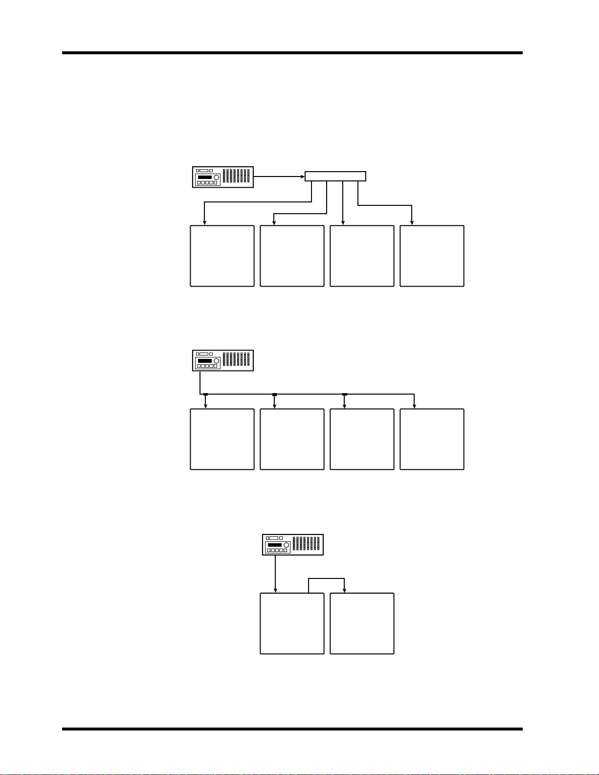
Wordclock Connection and Termination
For correct operation it is essential that wordclock cabling be terminated correctly. The 02R
features a wordclock termination ON/OFF (75
connections use BNC connectors. Wordclock is a TTL signal. Three wordclock distribution
examples are shown below. Note the 75
1. Parallel Distribution Box
Ω
) switch. Wordclock IN and OUT
Ω
wordclock terminator switch settings.
WORDCLOCK
OUT
WORDCLOCK IN WORDCLOCK IN WORDCLOCK IN WORDCLOCK IN
75Ω Switch=ON
75Ω Switch=ON 75Ω Switch=ON 75Ω Switch=ON
Distribution box
02R-A
02R-B 02R-C 02R-D
In this example, a parallel distribution box is used to distribute the wordclock signal among
the four 02Rs. All 02R wordclock terminator switches are set to ON.
2. Using BNC T-bar Connectors
WORDCLOCK
OUT
IN
WORDCLOCK
75Ω Switch=OFF
02R-A
IN
WORDCLOCK
75Ω Switch=OFF
02R-B
IN
WORDCLOCK
75Ω Switch=OFF
02R-C
IN
WORDCLOCK
75Ω Switch=ON
02R-D
This example is similar to the above except that T-bar connectors are used. In this system,
only the last 02R’s wordclock terminator switch is set to ON.
3. Daisy Chain Distribution
In this example, the wordclock master is a digital multitrack recorder. Both 02R wordclock
terminator switches are set to ON. This method of wordclock distribution is not
recommended for large systems.
Yamaha 02R & 03D Applications Guide
WORDCLOCK
OUT
IN OUT
WORDCLOCK
75Ω Switch=ON
02R-A
IN OUT
WORDCLOCK
75Ω Switch=ON
02R-B
02R Applications 9
Wordclocks
When several digital audio devices are configured in a system, it is essential that they are all
synchronized to a single wordclock source. This is not SMPTE or MIDI timecode
synchronization. Wordclock synchronization refers to the synchronization of the digital
audio processing components inside each digital audio device. Typically, one digital audio
device acts as wordclock master and all other devices work as wordclock slaves. The
wordclock frequency is the same as the chosen sampling rate.
Even though some systems appear to work okay with several digital audio devices not
sharing a common wordclock (i.e., all devices set to their own internal wordclock), digital
audio data will not be processed correctly. In some systems this problem will be very
audible. In others it may cause subtle distortion. Be aware of this.
In a system where all devices share a common wordclock, it is important that all devices be
powered on even if just one or two devices are being used. Obviously, the wordclock master
device must be powered on. Before starting a recording session it’s a good idea to make sure
that all wordclock slaves are locked to the master wordclock source. Most devices have front
panel indicators that show whether they are locked to internal or external wordclock.
02R
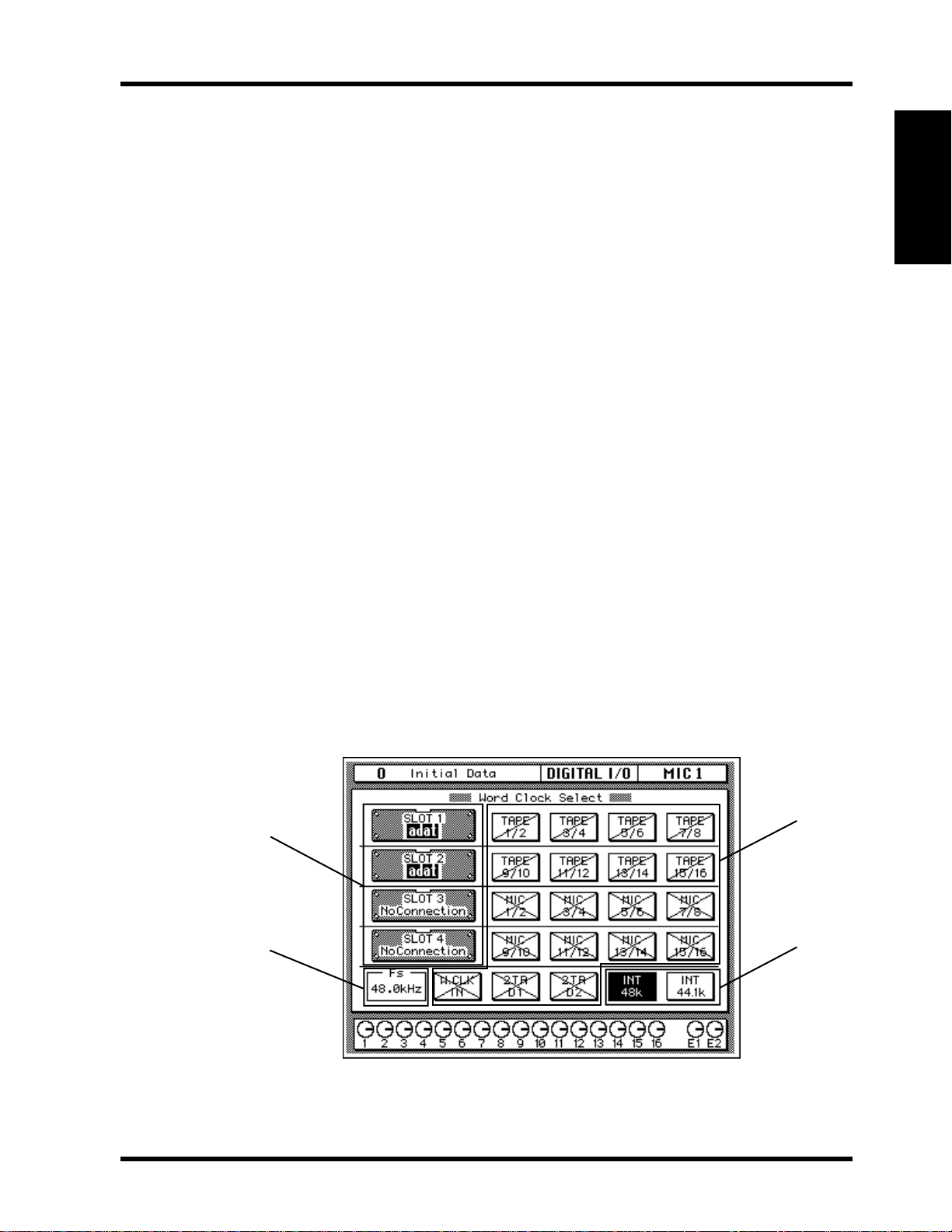
Setting the 02R’s Wordclock
To set the 02R’s wordclock source:
1. Press the DIGITAL I/O button repeatedly until the Word Clock Select display appears.
2. Use the cursor button to select a wordclock source.
3. Press the ENTER button.
If the 02R locks correctly to the chosen wordclock source, the respective indicator appears
22
22
highlighted. See “
the indicators.
As well as internal, the 02R can derive its wordclock from any one of 19 input options. It’s a
good idea to familiarize yourself with the various indicators on the Word Clock Select
display shown below. The four sections of the display, 11
11
11
Wordclock Source Capable Inputs” on page 10 for a full discussion of
11
44
to 44
, are explained below.
22
22
44
44
33
33
Yamaha 02R & 03D Applications Guide
10 02R Applications
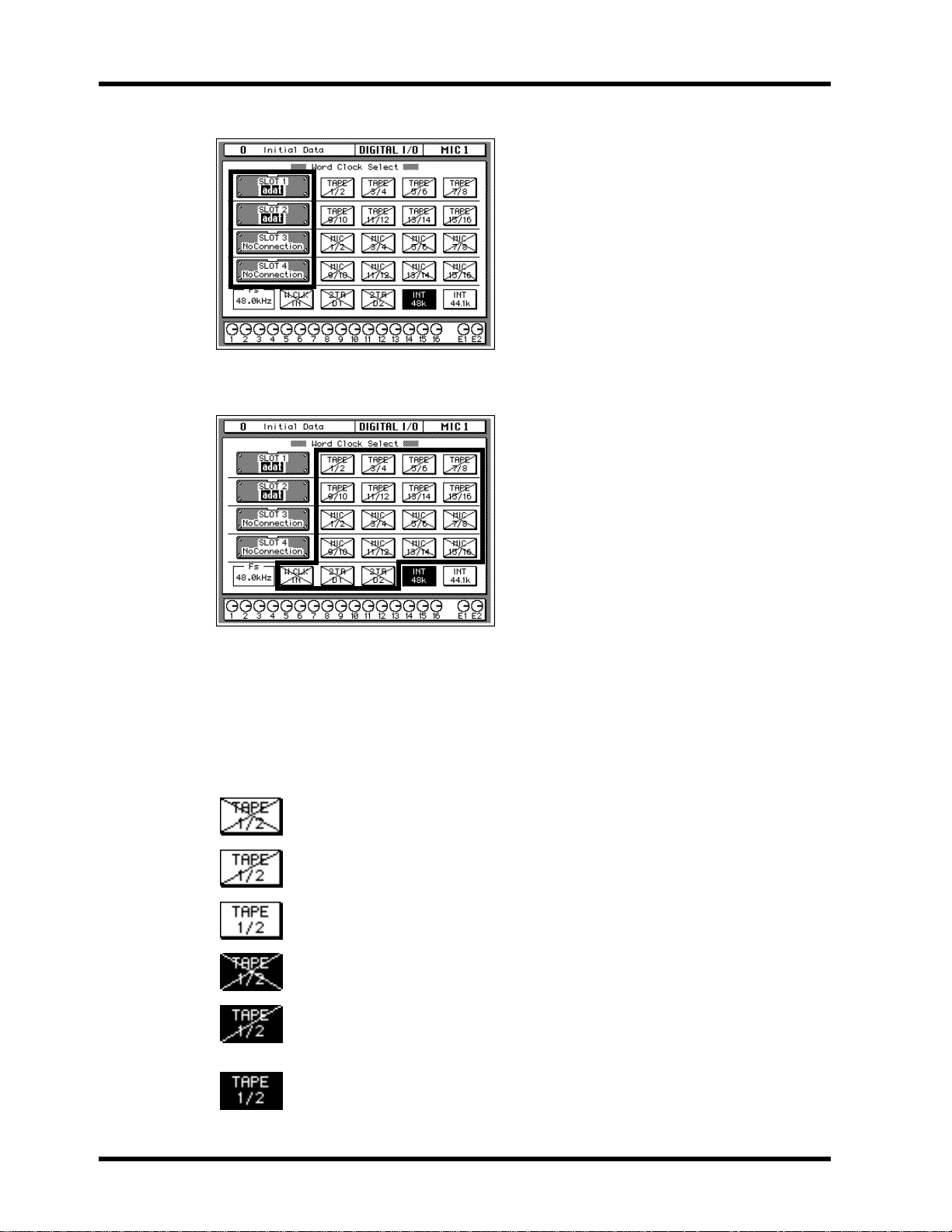
11
11
The Four Slots
22
22
Wordclock Source Capable Inputs
This section of the Word Clock Select display
indicates the type of interface cards installed in
the four slots. The following are possible:
TASCAM
adat
AES/EBU
YAMAHA
CASCADE
ANALOG
No Connection
This section of the Word Clock Select display is
used to set the 02R’s external wordclock source.
The four options to the left of each SLOT box
correspond to the inputs that are available via
that particular slot. The following options are
available.
TAPE 1/2–7/8—Row 1
TAPE 9/10–15/16—Row 2
MIC 1/2–7/8—Row 3
MIC 9/10–15/16—Row 4
W.CLK IN—Row 5 (BNC wordclock input)
2TR D1—Row 5 (2TR IN 1 AES/EBU input)
2TR D2—Row 5 (2TR IN 2 COAXIAL input)
The 02R’s wordclock source is set by selecting one of these indicators with the cursor
buttons, and then pressing the ENTER button.
The status of the wordclock capable inputs is indicated by crosses, single diagonal lines, and
highlights. The key to these indicators follows.
No wordclock signal is present at this input.
A wordclock signal is present at this input but it’s unlocked.
A wordclock signal is present at this input and it’s locked.
This input is selected as the wordclock source, however, no wordclock signal is
present.
This input is selected as the wordclock source and a wordclock signal is
present. However, you should check the wordclock connections and the
relationship between wordclock master and slaves.
This input is selected as the wordclock source, a wordclock signal is present,
and the 02R is correctly locked to it.
Yamaha 02R & 03D Applications Guide
02R Applications 11
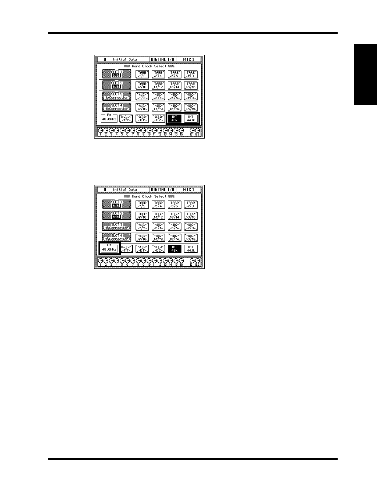
333302R Internal Wordclock (Sampling Rate)
This section of the Word Clock Select display is
used to set the 02R’s internal wordclock rate.
The following options are available.
INT 48k
INT 44.1k
In this example the internal sampling rate is set
to 48 kHz, as shown by the highlighted box.
The 02R’s wordclock source is set to one of these two internal options by selecting either 48k
or 44.1k with the cursor buttons, and then pressing the ENTER button.
4444Actual Wordclock Rate
02R
This section of the Word Clock Select display
shows the actual wordclock frequency, internal
or external, to within one decimal place.
Yamaha 02R & 03D Applications Guide

12 02R Applications
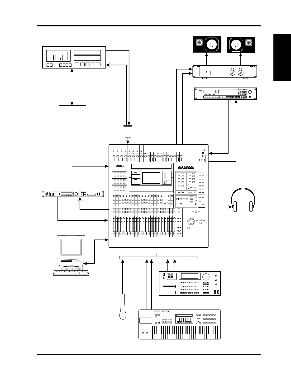
02R with One ADAT (Timecode on Tape Track)
1
This application shows how the 02R can be used with one Alesis ADAT to create a 24-input,
8-track digital recording system. As shown in Figure 1, track eight of the ADAT has been
striped with SMPTE timecode. This is then fed to the 02R’s SMPTE TIMECODE input
using a phone jack to phono cable.
The eight digital tape returns and 24 Mic/Line inputs provide up to 32 inputs at mixdown.
In addition, the 02R’s built-in automation and scene memory systems provide both
dynamic and static mix automation referenced to timecode.
Connections
• The ADAT (CD8-AT) cards must be screwed securely in place. Do not leave the screws
out after installation as the cards will not be grounded correctly.
• The Digital In/Out connectors on the 02R and ADATs are connected together using
Optical Cables. Press the DIGITAL IN button on the ADAT to use the DIGITAL IN.
• The ADAT is connected to Slot [1] of the 02R. These tape inputs correspond to tracks
one through eight.
• ADAT track eight is striped with SMPTE timecode. ADAT track eight analog out (phone
jack) is connected directly to the 02R’s SMPTE TIMECODE input (phono).
02R Wordclock Setup
An ADAT (CD8-AT) card is installed in Slot [1], so any one of the first 8 tape inputs can be
selected as the wordclock source on the DIGITAL I/O menu.
In Figure 1 the ADAT is shown as wordclock master. However, it could alternatively be used
as wordclock slave with the 02R as master. In this case, the ADAT would be set to “digi”. This
can be confirmed by pressing the DIGITAL IN and SET LOCATE buttons together. The
internal clock can then be set on the 02R
ADAT Wordclock Setup
The ADAT should be set as wordclock master. To confirm this, press the SET LOCATE and
DIGITAL IN buttons together. The display should show “int”, meaning internal wordclock.
The ADAT sampling rate can be set to either 48 kHz or 44.1 kHz. Use Fixed mode for
48 kHz and Variable mode for 44.1 kHz (using the PITCH DOWN button, set to –147 cents.
At which point “–146, 44.1, –148” appears on the display). The newer ADAT-XT has
dedicated switches for selecting these two sampling rates.
Notes
• Press the DIGITAL IN button on the ADAT to use the DIGITAL INPUT.
Yamaha 02R & 03D Applications Guide

02R Applications 13
ADAT
DIGITAL IN=ON
TRACK 8
ANALOG OUT
(Phone jack)
SMPTE timecode
SMPTE
TIMECODE
INPUT
(phono)
DIGITAL
OUTPUT
DIGITAL
INPUT
Optical cables
CD8-AT
1
Interface Card
C-R Out
DIGITAL RECORDING CONSOLE
Power Amp
02R
DAT Recorder
DAT
2TR IN
DIGITAL
STEREO OUT
DIGITAL
Effects processor
88
AUX SEND
INPUT 17-24
TO HOST
Headphones
MIC/LINE Inputs 1–24
MIDI Sampler
MIDI keyboard
Mic
Figure 1 02R with One ADAT (Timecode on Tape Track)
Yamaha 02R & 03D Applications Guide

14 02R Applications
02R with ADAT & JL Cooper Datasync-2
2
This application shows how the 02R can be used with a JL Cooper Datasync-2 Synchronizer
to create a 24-input, 8-track digital recording system. The JL Cooper Datasync-2
Synchronizer is a cost-effective device for setting up a synchronized 02R and ADAT system.
The eight digital tape returns and 24 Mic/Line inputs provide up to 32 inputs at mixdown.
In addition, the 02R’s built-in automation and scene memory systems provide both
dynamic and static mix automation referenced to MIDI timecode.
Connections
• The ADAT (CD8-AT) card must be screwed securely in place. Do not leave the screws out
after installation as the card will not be grounded correctly.
• The Digital In/Out connectors on the 02R and ADAT are connected together using
Optical Cables. Press the DIGITAL IN button on the ADAT to use the DIGITAL IN.
• The ADAT’s eight tracks connect to 02R slot [1], tape inputs one through eight.
• The JL Cooper Datasync-2 Synchronizer converts the ADAT’s internal timecode to MIDI
timecode or SMPTE timecode.
• A 9-pin Sync cable for connecting the ADAT and Datasync-2 is available from Alesis.
02R Wordclock Setup
The ADAT (CD8-AT) card is installed in Slot [1], so any pair of the first eight tape inputs
can be selected as the wordclock source on the DIGITAL I/O menu.
ADAT Wordclock Setup
The ADAT should be set as wordclock master. To confirm this, press the SET LOCATE and
DIGITAL IN buttons together. The display should show “int”, meaning internal wordclock.
The ADAT sampling rate can be set to either 48 kHz or 44.1 kHz. Use Fixed mode for
48 kHz and Variable mode for 44.1 kHz (using the PITCH DOWN button, set to –147 cents.
At which point “–146, 44.1, –148” appears on the display). The newer ADAT-XT has
dedicated switches for selecting these two sampling rates.
In Figure 2 the ADAT is shown as wordclock master. However, it could alternatively be used
as wordclock slave with the 02R as master. In this case, the ADAT would be set to “digi”. This
can be confirmed by pressing the DIGITAL IN and SET LOCATE buttons together. The
internal clock can then be set on the 02R.
Notes
• Press the DIGITAL IN button on the ADAT to use the DIGITAL INPUT.
Yamaha 02R & 03D Applications Guide
02R Applications 15
ADAT
DIGITAL IN=ON
SYNC IN
9-pin cableMIDI timecode
SYNC OUT
JL Cooper
Datasync-2
GEN OUT
(or SMPTE)
TIMECODE
MIDI
INPUT
DIGITAL
OUTPUT
DIGITAL
INPUT
Optical cable
CD8-AT
1
Interface Card
C-R Out
DIGITAL RECORDING CONSOLE
Power Amp
02R
DAT Recorder
DAT
2TR IN
DIGITAL
STEREO OUT
DIGITAL
Effects processor
88
AUX SEND
INPUT 17-24
TO HOST
Headphones
MIC/LINE Inputs 1–24
MIDI Sampler
MIDI keyboard
Mic
Figure 2 02R with ADAT & JL Cooper Datasync-2
Yamaha 02R & 03D Applications Guide

16 02R Applications
02R with Two ADATs & JL Cooper Datasync-2
3
This application shows how the 02R can be used with two Alesis ADATs and JL Cooper
Datasync-2 Synchronizer to create a 24-input, 16-track digital recording system. The JL
Cooper Datasync-2 Synchronizer is a cost-effective device for setting up a synchronized 02R
and ADAT system.
The 16 digital tape returns and 24 Mic/Line inputs provide up to 40 inputs at mixdown. In
addition, the 02R’s built-in automation and scene memory systems provide both dynamic
and static mix automation referenced to MIDI timecode.
Connections
• The ADAT (CD8-AT) cards must be screwed securely in place. Do not leave the screws
out after installation as the cards will not be grounded correctly.
• The Digital In/Out connectors on the 02R and ADAT are connected together using
Optical Cables. Press the DIGITAL IN buttons on the ADATs to use the DIGITAL INs.
• ADAT–A is connected to Slot [1] of the 02R and the tape inputs correspond to tracks
one through eight.
• ADAT–B is connected to Slot [2] of the 02R and the tape inputs correspond to tracks
nine through sixteen.
• The JL Cooper Datasync-2 Synchronizer converts the ADAT’s internal timecode to MIDI
timecode or SMPTE timecode.
• 9-pin Sync cables for connecting the ADATs and Datasync-2 are available from Alesis.
02R Wordclock Setup
ADAT (CD8-AT) cards are installed in Slot [1]and Slot [2], so any pair of the tape inputs
can be selected as the wordclock source on the DIGITAL I/O menu.
ADAT Wordclock Setup
ADAT–A should be set as wordclock master. To confirm this, press the SET LOCATE and
DIGITAL IN buttons together. The display should show “int”, meaning internal wordclock.
The ADAT sampling rate can be set to either 48 kHz or 44.1 kHz. Use Fixed mode for
48 kHz and Variable mode for 44.1 kHz (using the PITCH DOWN button, set to –147 cents.
At which point “–146, 44.1, –148” appears on the display). The newer ADAT-XT has
dedicated switches for selecting these two sampling rates.
Notes
• Press the DIGITAL IN buttons on the ADATs to use the DIGITAL INPUTs.
• ADAT–B must be powered up before ADAT–A, because when ADAT–A is powered up it
checks how many ADATs are connected, allocates them device numbers, and
automatically sets the system word clock. ADAT–A works as Control Master.
Yamaha 02R & 03D Applications Guide
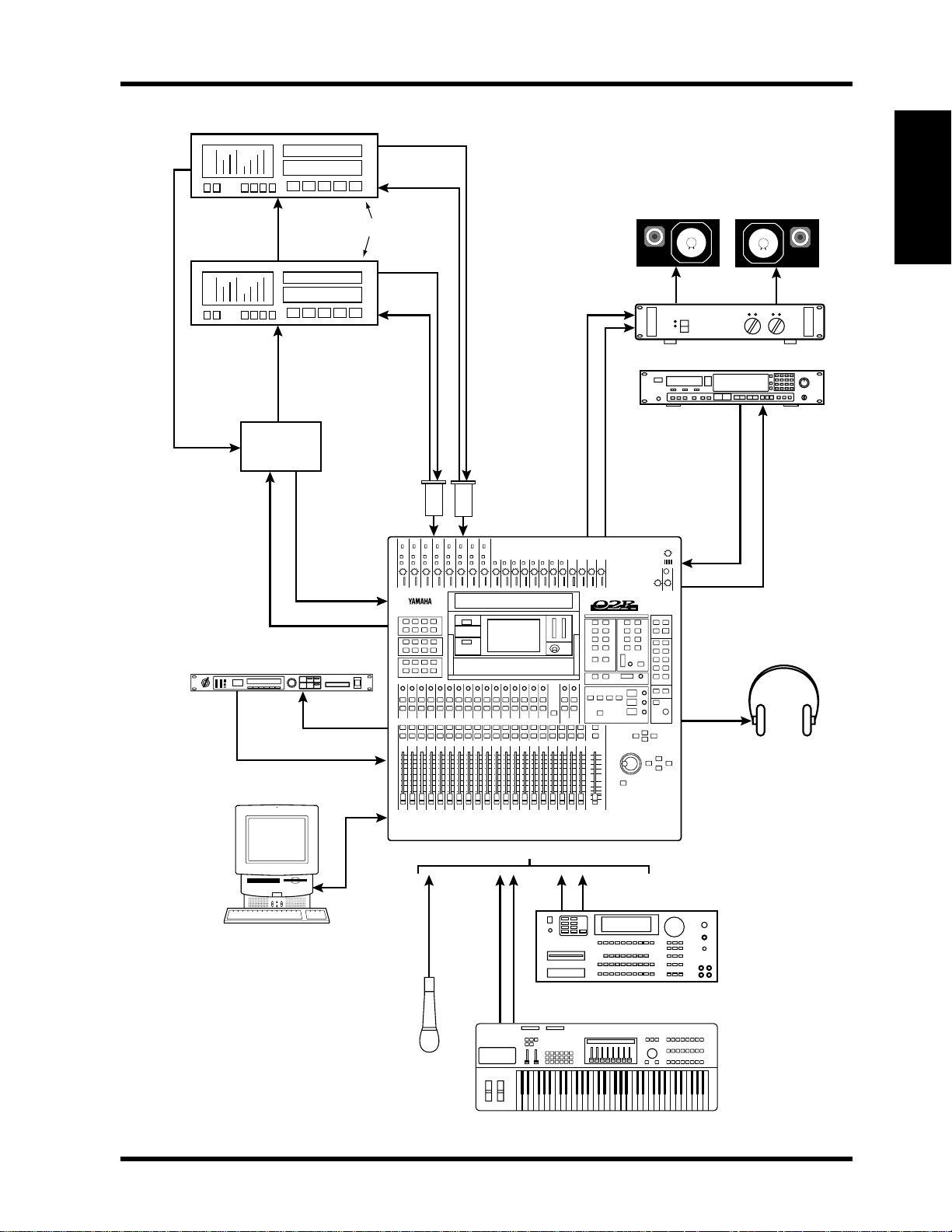
02R Applications 17
SYNC
OUT
ADAT–B
9-pin cable
ADAT–A
9-pin cable
To Sync
Out
MIDI IN
JL Cooper
Datasync-2
MMC
SYNC IN
SYNC OUT
SYNC IN
9-pin cable
To Sync In
MIDI OUT
MTC
DIGITAL
OUTPUT
DIGITAL
INPUT
DIGITAL IN=ON
DIGITAL
OUTPUT
DIGITAL
INPUT
1
Optical cables
CD8-AT
2
Interface Cards
C-R Out
02R
Power Amp
DAT Recorder
DAT
2TR IN
DIGITAL
Effects processor
88
MIDI IN
MIDI OUT
AUX SEND
INPUT 17-24
TO HOST
MIC/LINE Inputs 1–24
DIGITAL RECORDING CONSOLE
MIDI Sampler
MIDI keyboard
STEREO OUT
DIGITAL
Headphones
Mic
Figure 3 02R with Two ADATs & JL Cooper Datasync-2
Yamaha 02R & 03D Applications Guide

18 02R Applications
02R with ADAT & BRC
4
This application shows how the 02R can be used with an Alesis ADAT and BRC Master
Remote Control to create a 24-input, 8-track digital recording system. The eight digital tape
returns and 24 Mic/Line inputs provide up to 32 inputs at mixdown. In addition, the 02R’s
built-in automation and scene memory systems provide both dynamic and static mix
automation referenced to timecode.
Connections
• The ADAT (CD8-AT) card must be screwed securely in place. Do not leave the screws out
after installation as the card will not be grounded correctly.
• The Digital In/Out connectors on the 02R and ADAT are connected together using
Optical Cables. Press the DIGITAL IN button on the ADAT to use the DIGITAL IN.
• The ADAT’s eight tracks connect to 02R slot [1], tape inputs one through eight.
• The Alesis BRC Master Remote Control can control up to 16 ADATs (i.e. 128 tracks).
• A 9-pin sync cable for connecting the ADAT and BRC is available from Alesis.
• The BRC provides ADAT timecode to SMPTE timecode conversion. In addition, a
timecode offset can be specified, so the automix start time can be adjusted.
• The 75 ohm wordclock termination switch on the back of the 02R is set to ON.
02R Wordclock Setup
On the DIGITAL I/O menu, the wordclock source should be set to W.CLK.
ADAT & BRC Wordclock Setup
The BRC works as wordclock master and the ADAT locks to it automatically via the 9-pin
sync cable. The sampling rate can be set to either 48 kHz or 44.1 kHz. Use Fixed mode for
48 kHz and Variable mode for 44.1 kHz (using the PITCH DOWN button, set to –147 cents.
At which point “–146, 44.1, –148” appears on the display). The newer ADAT-XT has
dedicated switches for selecting these two sampling rates.
Notes
• Press the DIGITAL IN button on the ADAT to use the DIGITAL INPUT.
• The ADAT must be powered up before the BRC, because when the BRC is powered up it
checks how many ADATs are connected, allocates them device numbers, and
automatically sets the system wordclock.
• To generate timecode on the BRC, press the GEN SYNC button.
• On the BRC, set the DIGITAL I/O button to OFF. This function is for direct ping-pong
between multiple ADATs. If this is turned ON while connected to an 02R, bus
assignments will produce unexpected results. Press the DIGITAL IN button on the
ADAT to use the DIGITAL INPUT.
Yamaha 02R & 03D Applications Guide
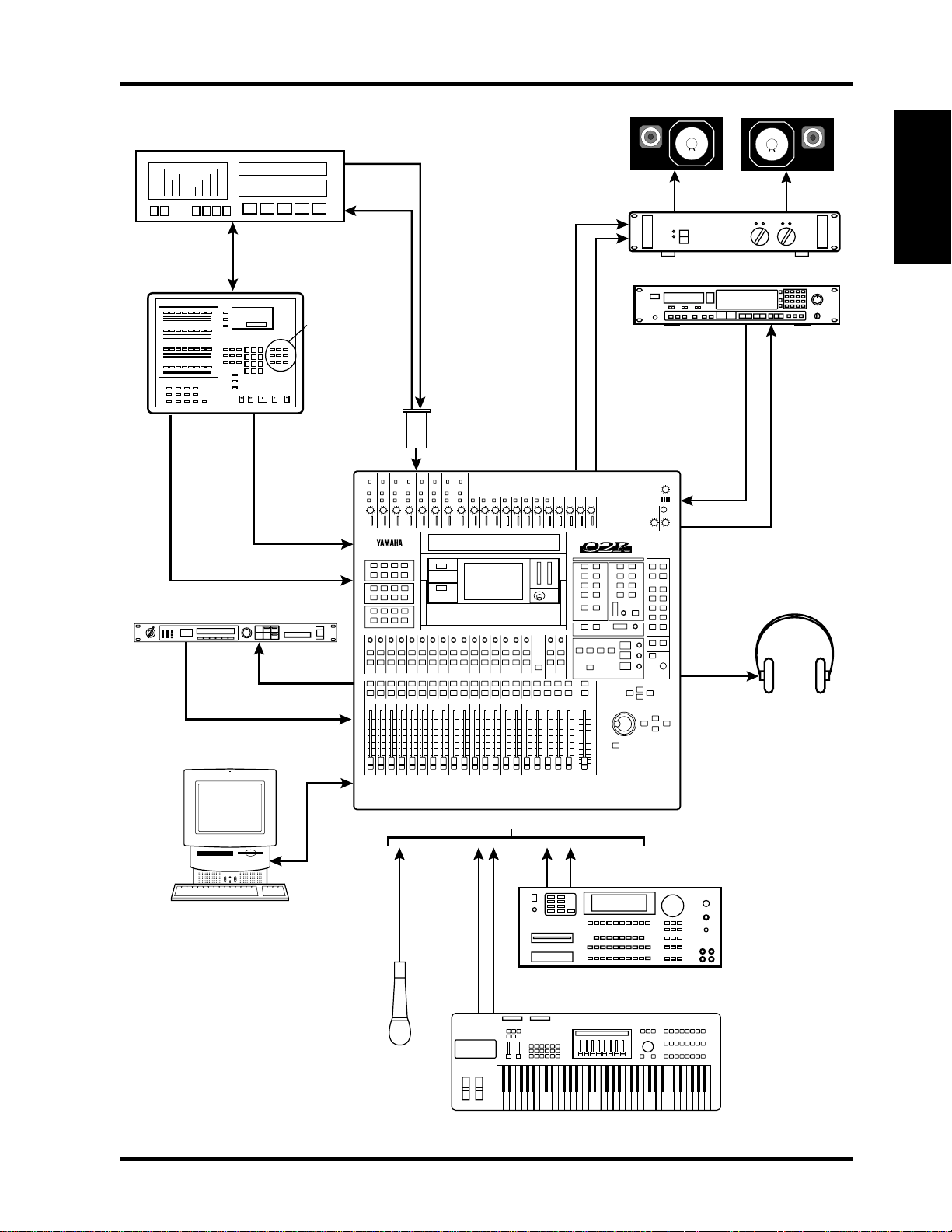
02R Applications 19
ADAT
DIGITAL IN=ON
SYNC IN
9-pin cable
BRC
SYNC OUT
00.00.00.00
WC OUT
(BNC)
WORDCLOCK IN (BNC)
Effects processor
88
DIGITAL
OUTPUT
DIGITAL
INPUT
GEN SYNC=ON
DIGITAL I/O=OFF
SMPTE OUT
SMPTE
TIMECODE
INPUT
(phono)
SMPTE timecode
(75Ω=ON)
Optical cable
CD8-AT
1
Interface Card
C-R Out
DIGITAL RECORDING CONSOLE
Power Amp
02R
DAT Recorder
DAT
2TR IN
DIGITAL
STEREO OUT
DIGITAL
AUX SEND
INPUT 17-24
TO HOST
Headphones
MIC/LINE Inputs 1–24
MIDI Sampler
MIDI keyboard
Mic
Figure 4 02R with ADAT & BRC
Yamaha 02R & 03D Applications Guide

20 02R Applications
02R with Two ADATs & BRC
5
This application shows how the 02R can be used with two Alesis ADATs and a BRC Master
Remote Control to create a 24-input, 16-track digital recording system. The 16 digital tape
returns and 24 Mic/Line inputs provide up to 40 inputs at mixdown. In addition, the 02R’s
built-in automation and scene memory systems provide both dynamic and static mix
automation referenced to timecode.
Connections
• The ADAT (CD8-AT) cards must be screwed securely in place. Do not leave the screws
out after installation as the cards will not be grounded correctly.
• The Digital In/Out connectors on the 02R and ADAT are connected together using
Optical Cables. Press the DIGITAL IN buttons on the ADATs to use the DIGITAL IN.
• ADAT–A is connected to Slot [1] of the 02R and the tape inputs correspond to tracks
one through eight.
• ADAT–B is connected to Slot [2] of the 02R and the tape inputs correspond to tracks
nine through sixteen.
• The Alesis BRC Master Remote Control can control up to 16 ADATs (i.e. 128 tracks).
• A 9-pin sync cable for connecting the ADAT and BRC is available from Alesis.
• The BRC provides ADAT timecode to SMPTE timecode conversion. In addition, a
timecode offset can be specified, so the automix start time can be adjusted.
• The 75 ohm wordclock termination switch on the back of the 02R is set to ON.
02R Wordclock Setup
On the DIGITAL I/O menu, the wordclock source should be set to W.CLK.
ADAT & BRC Wordclock Setup
The BRC works as wordclock master and the two ADATs locks to it automatically via the
9-pin sync cables. The sampling rate can be set to either 48 kHz or 44.1 kHz. Use Fixed
mode for 48 kHz and Variable mode for 44.1 kHz (using the PITCH DOWN button, set to
–147 cents. At which point “–146, 44.1, –148” appears on the display). The newer ADAT-XT
has dedicated switches for selecting these two sampling rates.
Notes
• The ADATs must be powered up before the BRC and in the following order: B then A.
This is because when the BRC is powered up it checks how many ADATs are connected,
allocates them device numbers, and automatically sets the system clock.
• To generate timecode on the BRC, press the GEN SYNC button.
• On the BRC, set the DIGITAL I/O button to OFF. This function is for direct ping-pong
between multiple ADATs. If this is turned ON while connected to an 02R, bus
assignments will produce unexpected results. Press the DIGITAL IN button on the
ADAT to use the DIGITAL INPUT.
Yamaha 02R & 03D Applications Guide
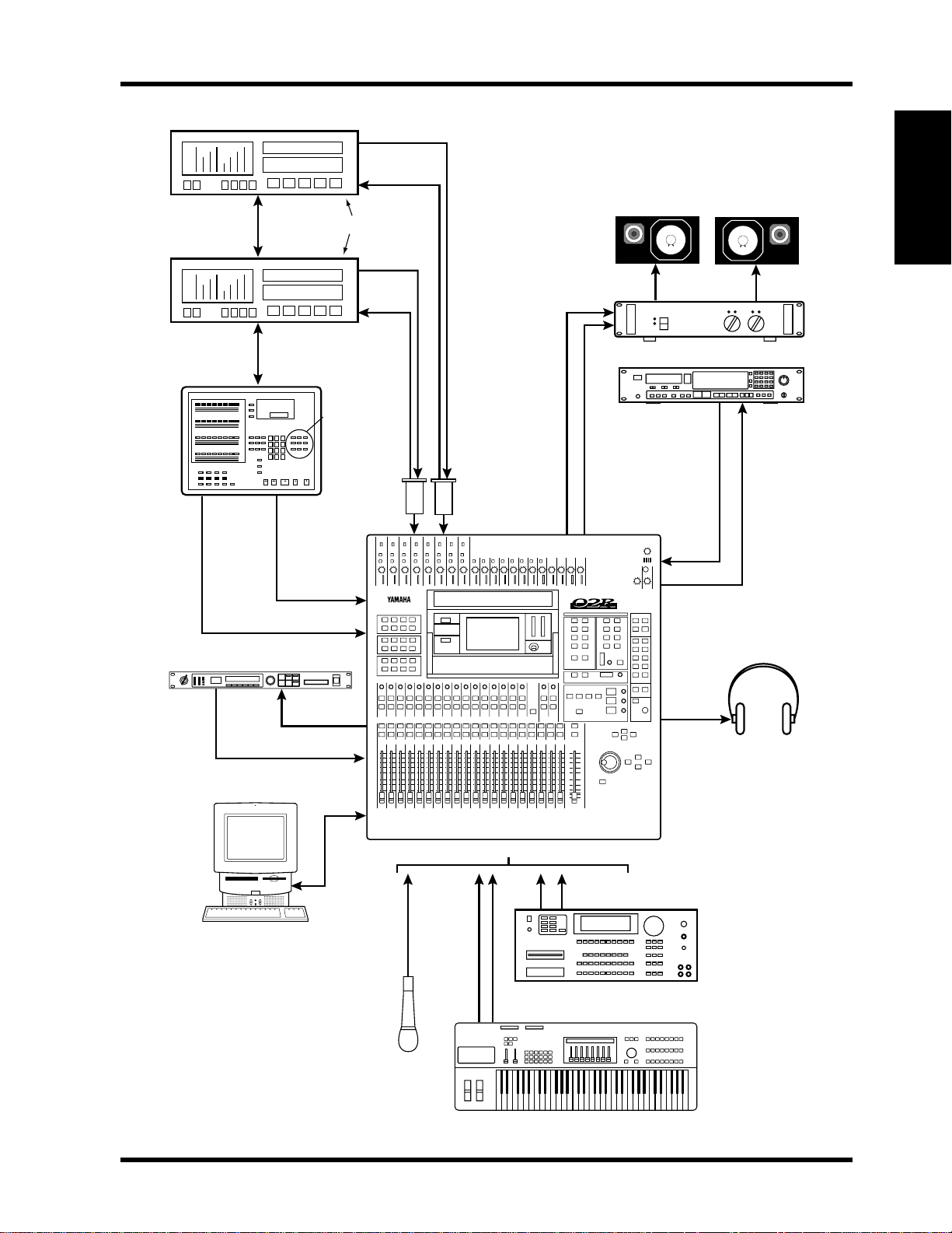
02R Applications 21
ADAT–B
SYNC IN
9-pin cable
ADAT–A
9-pin cable
BRC
WC OUT
(BNC)
WORDCLOCK IN (BNC)
Effects processor
88
SYNC OUT
SYNC IN
SYNC OUT
00.00.00.00
DIGITAL
OUTPUT
DIGITAL
INPUT
DIGITAL IN=ON
DIGITAL
OUTPUT
DIGITAL
INPUT
GEN SYNC=ON
DIGITAL I/O=OFF
SMPTE OUT
SMPTE
TIMECODE
INPUT
(phono)
SMPTE timecode
(75Ω=ON)
Optical cables
CD8-AT
1
2
Interface Cards
C-R Out
DIGITAL RECORDING CONSOLE
02R
Power Amp
DAT Recorder
DAT
2TR IN
DIGITAL
STEREO OUT
DIGITAL
AUX SEND
INPUT 17-24
TO HOST
MIC/LINE Inputs 1–24
Mic
Figure 5 02R with Two ADATs & BRC
Headphones
MIDI Sampler
MIDI keyboard
Yamaha 02R & 03D Applications Guide

22 02R Applications
Two 02Rs with Four ADATs & BRC
6
This application shows how two 02Rs can be used with four Alesis ADATs and a BRC Master
Remote Control to create a 48-input, 32-track digital recording system. The 32 digital tape
returns and 48 Mic/Line inputs provide up to 80 inputs at mixdown. In addition, the 02R’s
built-in automation and scene memory systems provide both dynamic and static mix
automation referenced to timecode.
The two 02Rs are cascaded together using a 25-pin straight cable and two Cascade
(CD8-CS) cards, which are installed in Slot [3] of each 02R (could be Slot [4]). The
cascade connection carries the eight buses, any four of the eight AUX buses, Stereo bus, and
Solo bus. This allows both consoles to work together as one large 80-input mixing console.
The master section of 02R–B is used for monitoring and two-track operations. The studio
monitors and two-track recording equipment are also connected to this 02R.
Connections
• The ADAT (CD8-AT) and Cascade (CD8-CS) cards must be screwed securely in place.
Do not leave the screws out after installation as the cards will not be grounded correctly.
• The Digital In/Out connectors on the 02R and ADAT are connected together using the
Optical Cable. Press the DIGITAL IN buttons on the ADATs to use the DIGITAL IN.
• ADAT–A is connected to Slot [1] of 02R–A and the tape inputs correspond to tracks one
through eight. ADAT–B is connected to Slot [2] of 02R–A and the tape inputs
correspond to tracks nine through sixteen. ADAT–C is connected to Slot [1] of 02R–B
and the tape inputs correspond to tracks 17 through 24. ADAT–D is connected to Slot
[2] of 02R–B and the tape inputs correspond to tracks 25 through 32.
• The Alesis BRC Master Remote Control can control up to 16 ADATs (i.e. 128 tracks).
• The BRC provides ADAT timecode to SMPTE timecode conversion. In addition, a
timecode offset can be specified, so the automix start time can be adjusted.
• The 75 ohm wordclock termination switches on both 02Rs is set to ON.
02R Wordclock Setup
On the DIGITAL I/O menu, the wordclock source should be set to W.CLK.
ADAT & BRC Wordclock Setup
The BRC works as wordclock master and the four ADATs follows it automatically via the
9-pin sync cables. The sampling rate can be set to either 48 kHz or 44.1 kHz. Use Fixed
mode for 48 kHz and Variable mode for 44.1 kHz (using the PITCH DOWN button, set to
–147 cents. At which point “–146, 44.1, –148” appears on the display). The newer ADAT-XT
has dedicated switches for selecting these two sampling rates.
Notes
• The ADATs must be powered up before the BRC and in the following order: D, C, B, A.
This is because when the BRC is powered up it checks how many ADATs are connected,
allocates them device numbers, and automatically sets the system clock.
• The rear of the Cascade (CD8-CS) cards have an IN/OUT switch. On 02R–A is set to
OUT. On 02R–B it is set to IN.
• To generate timecode on the BRC, press the GEN SYNC button.
• The optional CD8-CS kit contains two CD8-CS cards and one 25-pin straight cable.
Yamaha 02R & 03D Applications Guide
 Loading...