


 Loading...
60 – 34 –
GAIN 7
(UNBAL) –10dBV
ON
OFF
+48V PHANTOM
|
|
L |
|
15 |
|
13 |
|
R |
|
|
|
|
16 |
IN |
|
|
|
|
14 |
|
OUT
2TR
PHONES
|
|
|
|
|
|
|
|
|
|
26dB |
|
|
|
|
|
|
|
|
|
26dB |
|
|
|
|
|
|
|
26dB |
|
|
|
|
|
|
– |
|
|
|
|
|
|
|
|
|
|
|
60 |
|
|
|
|
|
|
|
|
|
|
|
34 |
|
|
|
|
|
|
|
|
|
|
16 |
– |
|
|
|
|
|
|
|
|
|
|
GAIN |
|
|
|
|
|
|
|
|
|
|
|
– |
|
|
|
26dB |
|
|
|
|
|
|
– |
+10 |
|
|
|
|
|
|
|
|
|
|
60 |
|
|
|
|
|
|
|
|
|
|
|
34 |
|
12 |
Owner’s– |
|
|
16 |
– |
|
||||||
|
|
GAIN |
|
||||||||
|
|
– |
|
|
|
||||||
|
Manual |
||||||||||
26dB |
|
|
|
|
|
– |
+10 |
|
|
|
|
|
|
|
|
|
|
|
60 |
|
|
|
|
|
|
|
|
|
|
|
34 |
|
11 |
|
|
|
|
|
|
16 |
|
|
– |
|
|
|
|
|
|
|
|
GAIN |
|
|
|
|
|||
|
|
|
|
– |
|
|
|
|
|
|
|
|
|
|
60 |
+10 |
|
|
|
|
|
|
|
|
|
|
|
|
|
|
|
|
|
|
|
|
|
|
– |
|
|
|
|
|
|
|
|
|
|
16 |
34 |
|
10 |
|
|
|
|
||
|
|
GAIN |
|
|
|
|
|
||||
|
|
– |
|
|
|
|
|
|
|
|
|
|
60 |
+10 |
|
|
|
|
|
|
|
|
|
|
– |
|
9 |
|
|
|
|
|
|
|
|
– |
34 |
|
|
|
|
|
|
|
|
|
|
– |
|
|
|
|
|
|
|
|
|
||
16 |
|
|
|
|
|
|
|
|
|
|
|
GAIN |
|
|
|
|
|
|
|
|
|
|
|
+10 |
|
|
|
|
|
|
|
|
|
|
|
|
|
|
|
|
|
|
|
|
|
|
|
|
8 |
|
|
|
|
|
|
|
|
|
|
G

 15/16IN
  2TR
2TR
20 –
20 |
+10 |
GAIN |
|
||
|
|
|
– |
|
|
MONITORIN |
|
2TR |
|
|
10 |
0 |
LEVEL |
|
|
MONITOR |
|
|
OUT |
 10
10
0 |
LEVEL |
|
|
|
PHONES |
+10 |
GAIN |
15/16 |
|
|
13/14 |
|
|||
|
|
CONSOLE |
||
DIGITAL |
MIXING |
|
||
EQ |
HIGH |
|||
|
|
|||
|
|
|
||
|
|
PAN |
-MID |
|
|
|
|
||
|
|
|
HI |
|
|
|
F |
-MID |
|
|
|
|
LO |
|
|
|
|
LOW |
|
|
|
G |
||
|
R |
L |
STEREO |
|
|
|
CLIP |
|
3 |
|
– |
|
6 |
|
– |
|
9 |
|
– |
|
12 |
|
– |
|
15 |
|
– |
18 –
24 –
30 –
36 –
42 –
48 –
CHANNEL SELECTED
2
1 |
RETURN |
|
9
10 SEL


11 SEL
12 SEL
13/14 SEL
15/16 SEL
STEREO MASTER SEL
SOLO
SOLO
O
ON
|
2 |
1RETURN |
L |
SE |
|
SEL |
|
|
S |
SOLO |
|
E |
ON |
|

FCC INFORMATION (U.S.A.)
1.IMPORTANT NOTICE: DO NOT MODIFY THIS UNIT!
This product, when installed as indicated in the instructions contained in this manual, meets FCC requirements. Modifications not expressly approved by Yamaha may void your authority, granted by the FCC, to use the product.
2.IMPORTANT: When connecting this product to accessories and/or another product use only high quality shielded cables. Cable/s supplied with this product MUST be used. Follow all installation instructions. Failure to follow instructions could void your FCC authorization to use this product in the USA.
3.NOTE: This product has been tested and found to comply with the requirements listed in FCC Regulations, Part 15 for Class “B” digital devices. Compliance with these requirements provides a reasonable level of assurance that your use of this product in a residential environment will not result in harmful interference with other electronic devices. This equipment generates/uses radio frequencies and, if not installed and used according to the instructions found in the users manual, may cause interference harmful to the operation of other electronic devices. Compliance with FCC regulations does not guarantee that interference will not occur in all installations. If this product is found to be the source of interference, which can be determined by turning the unit “OFF” and “ON”, please try to eliminate the problem by using one of the following measures:
Relocate either this product or the device that is being affected by the interference.
Utilize power outlets that are on different branch (circuit breaker or fuse) circuits or install AC line filter/s.
In the case of radio or TV interference, relocate/reorient the antenna. If the antenna lead-in is 300 ohm ribbon lead, change the lead-in to coaxial type cable.
If these corrective measures do not produce satisfactory results, please contact the local retailer authorized to distribute this type of product. If you can not locate the appropriate retailer, please contact Yamaha Corporation of America, Electronic Service Division, 6600 Orangethorpe Ave, Buena Park, CA 90620
*This applies only to products distributed by YAMAHA CORPORATION OF AMERICA.
IMPORTANT NOTICE FOR
THE UNITED KINGDOM
Connecting the Plug and Cord
WARNING: THIS APPARATUS MUST BE EARTHED
IMPORTANT: The wires in this mains lead are coloured in accordance with the following code:
GREEN-AND-YELLOW : EARTH
BLUE |
: NEUTRAL |
BROWN |
: LIVE |
As the colours of the wires in the mains lead of this apparatus may not correspond with the coloured markings identifying the terminals in your plug, proceed as follows:
The wire which is coloured GREEN and YELLOW must be connected to the terminal in the plug which is marked by the letter E or by the safety earth symbol or coloured GREEN and YELLOW.
The wire which is coloured BLUE must be connected to the terminal which is marked with the letter N or coloured BLACK.
The wire which is coloured BROWN must be connected to the terminal which is marked with the letter L or coloured RED.
*This applies only to products distributed by YAMAHA KEMBLE MUSIC (U.K.) LTD.
ADVARSEL! Lithiumbatteri—Eksplosionsfare ved fejlagtig
håndtering. Udskiftning må kun ske med batteri af samme fabrikat og type. Levér det brugte batteri tilbage til leverandoren.
VARNING
Explosionsfara vid felaktigt batteribyte. Använd samma batterityp eller en ekvivalent typ som rekommenderas av apparattillverkaren. Kassera använt batteri enligt fabrikantens instruktion.
VAROITUS
Paristo voi räjähtää, jos se on virheellisesti asennettu. Vaihda paristo ainoastaan laitevalmistajan suosittelemaan tyyppiin. Hävitä käytetty paristo valmistajan ohjeiden mukaisesti.
NEDERLAND |
THE NETHERLANDS |
● Dit apparaat bevat een lithium batterij voor geheugen |
● This apparatus contains a lithium battery for memory |
back-up. |
back-up. |
● Raadpleeg uw leverancier over de verwijdering van de |
● For the removal of the battery at the moment of the |
batterij op het moment dat u het apparaat ann het einde |
disposal at the end of the service life please consult your |
van de levensduur afdankt of de volgende Yamaha Service |
retailer or Yamaha Service Center as follows: |
Afdeiing: |
Yamaha Music Nederland Service Center |
Yamaha Music Nederland Service Afdeiing |
Address: Kanaalweg 18-G, 3526 KL |
Kanaalweg 18-G, 3526 KL UTRECHT |
UTRECHT |
Tel. 030-2828425 |
Tel: 030-2828425 |
● Gooi de batterij niet weg, maar lever hem in als KCA. |
● Do not throw away the battery. Instead, hand it in as small |
|
chemical waste. |
|
|

i
Important Information
Read the Following Before Operating the 01V
Warnings
•Do not locate the 01V in a place subject to excessive heat or in direct sunlight. This could be a fire hazard.
•Do not place the 01V in a place subject to excessive humidity or dust. This could be a fire and electrical shock hazard.
•Connect the 01V power cord only to an AC outlet of the type stated in this Owner’s Manual or as marked on the 01V. Failure to do so is a fire and electrical shock hazard.
•Do not plug several devices into the same AC outlet. This can overload the AC outlet, and can be a fire and electrical shock hazard. It may also affect the performance of some devices.
•Do not place heavy objects on the power cord. A damaged power cord is a potential fire and electrical shock hazard.
•If the power cord is damaged (i.e., cut or a bare wire is exposed), ask your dealer for a replacement. Using the 01V in this condition is a fire and shock hazard.
•Hold the power cord plug when disconnecting from an AC outlet. Never pull the cord. Damaging the power cord in this way is a potential fire and electrical shock hazard.
•Do not place small metal objects on top of the 01V. Metal objects inside the 01V are a fire and electrical shock hazard.
•Do not block the 01V ventilation slots. The 01V has ventilation slots on the top and rear to prevent the internal temperature from rising. Blocked ventilation slots are a fire hazard.
•Do not try to modify the 01V. This could be a fire and electrical shock hazard.
•The 01V operating temperature is between 5˚C and 35˚C (41˚F and 95˚F).
Cautions
•Turn off all audio devices and speakers when connecting to the 01V. Refer to the owner’s manual for each device. Use the correct cables and connect as specified.
•If you notice any abnormality—such as smoke, odor, or noise—turn off the 01V immediately. Remove the power cord from the AC outlet. Confirm that the abnormality is no longer present. Consult your dealer for repair. Using the 01V in this condition is a fire and shock hazard.
•If a foreign object or water gets inside the 01V, turn it off immediately. Remove the power cord from the AC outlet. Consult your dealer for repair. Using the 01V in this condition is a fire and electrical shock hazard.
•If you plan not to use the 01V for a long period of time, remove the power cord from the AC outlet. Leaving the 01V connected is a fire hazard.
•Do not use benzene, thinner, cleaning detergent, or a chemical cloth to clean the 01V. Use only a soft, dry cloth.
•The 01V is a heavy piece of equipment. Always grip the underneath, not the side panels, when lifting.
01V—Owner’s Manual

ii
Interference
01V uses high-frequency digital circuits that may cause interference on radios and televisions placed close to it. If interference does occur, relocate the affected equipment.
Copyright
© 1998 Yamaha Corporation. All rights reserved.
No part of the 01V software or this Owner’s Manual may be reproduced or distributed in any form or by any means without the prior written authorization of Yamaha Corporation.
Trademarks
ADAT MultiChannel Optical Digital Interface is a trademark and ADAT and Alesis are registered trademarks of Alesis Corporation. Macintosh is a registered trademark of Apple Computer, Inc. Pro Tools is a registered trademark of Digidesign or Avid Technology, Inc. Tascam Digital Interface is a trademark and Tascam and TEAC are registered trademarks of TEAC Corporation. Windows is a trademark of Microsoft Corporation.
All other trademarks are the property of their respective holders and are hereby acknowledged.
Package Contents
The 01V package should contain the following items. Make sure that you have them all.
•01V Digital Mixing Console
•Owner’s Manual
Contact your Yamaha dealer if anything is missing.
Keep this manual for future reference!
01V—Owner’s Manual

|
Contents |
iii |
|
Contents |
|
1 Welcome to the 01V . . . . . . . . . . . . . . . . . . . . . . . . |
1 |
|
|
Welcome to the 01V . . . . . . . . . . . . . . . . . . . . . . . . . . . . . . . . . . . . . . . . . |
2 |
|
About this Owner’s Manual . . . . . . . . . . . . . . . . . . . . . . . . . . . . . . . . . . . |
2 |
|
01V Installation . . . . . . . . . . . . . . . . . . . . . . . . . . . . . . . . . . . . . . . . . . . . . |
2 |
|
01V Features . . . . . . . . . . . . . . . . . . . . . . . . . . . . . . . . . . . . . . . . . . . . . . . . |
3 |
|
Key Feature Discussion . . . . . . . . . . . . . . . . . . . . . . . . . . . . . . . . . . . . . . . |
4 |
2 |
Getting Started . . . . . . . . . . . . . . . . . . . . . . . . . . . . |
9 |
|
01V System Example . . . . . . . . . . . . . . . . . . . . . . . . . . . . . . . . . . . . . . . . |
10 |
|
Important Wordclock Information . . . . . . . . . . . . . . . . . . . . . . . . . . . . |
11 |
|
Connecting the Power Cord . . . . . . . . . . . . . . . . . . . . . . . . . . . . . . . . . . |
11 |
|
Turning On the 01V . . . . . . . . . . . . . . . . . . . . . . . . . . . . . . . . . . . . . . . . |
11 |
|
Turning Off the 01V . . . . . . . . . . . . . . . . . . . . . . . . . . . . . . . . . . . . . . . . |
11 |
3 |
Touring the 01V . . . . . . . . . . . . . . . . . . . . . . . . . . . |
13 |
|
Top Panel Controls . . . . . . . . . . . . . . . . . . . . . . . . . . . . . . . . . . . . . . . . . |
14 |
|
Inputs & Outputs . . . . . . . . . . . . . . . . . . . . . . . . . . . . . . . . . . . . . . . . . . . |
20 |
|
Block Diagram . . . . . . . . . . . . . . . . . . . . . . . . . . . . . . . . . . . . . . . . . . . . . |
24 |
4 Getting Around the User Interface . . . . . . . . . . . . |
27 |
|
|
About the User Interface . . . . . . . . . . . . . . . . . . . . . . . . . . . . . . . . . . . . . |
28 |
|
Display . . . . . . . . . . . . . . . . . . . . . . . . . . . . . . . . . . . . . . . . . . . . . . . . . . . |
28 |
|
Display Elements . . . . . . . . . . . . . . . . . . . . . . . . . . . . . . . . . . . . . . . . . . . |
30 |
|
Cursor Buttons . . . . . . . . . . . . . . . . . . . . . . . . . . . . . . . . . . . . . . . . . . . . . |
31 |
|
PARAMETER Wheel . . . . . . . . . . . . . . . . . . . . . . . . . . . . . . . . . . . . . . . . |
31 |
|
–1/DEC & +1/INC Buttons . . . . . . . . . . . . . . . . . . . . . . . . . . . . . . . . . . . |
31 |
|
ENTER Button . . . . . . . . . . . . . . . . . . . . . . . . . . . . . . . . . . . . . . . . . . . . . |
31 |
|
Fader Modes . . . . . . . . . . . . . . . . . . . . . . . . . . . . . . . . . . . . . . . . . . . . . . . |
32 |
|
Title Edit Dialog Box . . . . . . . . . . . . . . . . . . . . . . . . . . . . . . . . . . . . . . . . |
37 |
5 |
Input Channels . . . . . . . . . . . . . . . . . . . . . . . . . . . |
39 |
|
Input Channel Overview . . . . . . . . . . . . . . . . . . . . . . . . . . . . . . . . . . . . . |
40 |
|
Phantom Powering . . . . . . . . . . . . . . . . . . . . . . . . . . . . . . . . . . . . . . . . . |
41 |
|
Pad Switches . . . . . . . . . . . . . . . . . . . . . . . . . . . . . . . . . . . . . . . . . . . . . . . |
41 |
|
Setting Input Channel Gain . . . . . . . . . . . . . . . . . . . . . . . . . . . . . . . . . . |
41 |
|
Metering Input Channels . . . . . . . . . . . . . . . . . . . . . . . . . . . . . . . . . . . . |
41 |
|
Changing the Input Phase . . . . . . . . . . . . . . . . . . . . . . . . . . . . . . . . . . . . |
42 |
|
Attenuating Input Channel Signals . . . . . . . . . . . . . . . . . . . . . . . . . . . . |
43 |
|
Applying EQ to Input Channels . . . . . . . . . . . . . . . . . . . . . . . . . . . . . . . |
44 |
|
Input Channels Dynamics Processors . . . . . . . . . . . . . . . . . . . . . . . . . . |
44 |
|
Delaying Channel Signals . . . . . . . . . . . . . . . . . . . . . . . . . . . . . . . . . . . . |
45 |
|
Muting Input Channels . . . . . . . . . . . . . . . . . . . . . . . . . . . . . . . . . . . . . . |
46 |
|
Setting Input Channel Levels . . . . . . . . . . . . . . . . . . . . . . . . . . . . . . . . . |
46 |
|
Panning Input Channels . . . . . . . . . . . . . . . . . . . . . . . . . . . . . . . . . . . . . |
47 |
|
Routing Input Channels . . . . . . . . . . . . . . . . . . . . . . . . . . . . . . . . . . . . . |
49 |
|
Monitoring Input Channels . . . . . . . . . . . . . . . . . . . . . . . . . . . . . . . . . . |
50 |
|
Input Channels & Aux Sends . . . . . . . . . . . . . . . . . . . . . . . . . . . . . . . . . |
50 |
01V—Owner’s Manual

iv Contents
Input Channels & the Omni Outs . . . . . . . . . . . . . . . . . . . . . . . . . . . . . 50 Input Channels & the Option I/O Outs . . . . . . . . . . . . . . . . . . . . . . . . . 50 Swapping Inputs 1–8 & 17–24 . . . . . . . . . . . . . . . . . . . . . . . . . . . . . . . . 51 Pairing Input Channels . . . . . . . . . . . . . . . . . . . . . . . . . . . . . . . . . . . . . . 52 Grouping Faders . . . . . . . . . . . . . . . . . . . . . . . . . . . . . . . . . . . . . . . . . . . 55 Grouping Mutes . . . . . . . . . . . . . . . . . . . . . . . . . . . . . . . . . . . . . . . . . . . . 56 Viewing Input Channel Settings . . . . . . . . . . . . . . . . . . . . . . . . . . . . . . . 57 Copying & Swapping Channel Settings . . . . . . . . . . . . . . . . . . . . . . . . . 59 Input Channel Block Diagram . . . . . . . . . . . . . . . . . . . . . . . . . . . . . . . . 60
6 EQ . . . . . . . . . . . . . . . . . . . . . . . . . . . . . . . . . . . . . . 61
About the 01V EQ . . . . . . . . . . . . . . . . . . . . . . . . . . . . . . . . . . . . . . . . . . 62
Adjusting the EQ . . . . . . . . . . . . . . . . . . . . . . . . . . . . . . . . . . . . . . . . . . . 63
EQ Specs . . . . . . . . . . . . . . . . . . . . . . . . . . . . . . . . . . . . . . . . . . . . . . . . . . 66
Bypassing the EQ . . . . . . . . . . . . . . . . . . . . . . . . . . . . . . . . . . . . . . . . . . . 66
Resetting the EQ . . . . . . . . . . . . . . . . . . . . . . . . . . . . . . . . . . . . . . . . . . . . 66
EQ Library . . . . . . . . . . . . . . . . . . . . . . . . . . . . . . . . . . . . . . . . . . . . . . . . 67
Preset EQ Program List . . . . . . . . . . . . . . . . . . . . . . . . . . . . . . . . . . . . . . 67
Storing EQ Programs . . . . . . . . . . . . . . . . . . . . . . . . . . . . . . . . . . . . . . . . 68
Recalling EQ Programs . . . . . . . . . . . . . . . . . . . . . . . . . . . . . . . . . . . . . . 69
Editing EQ Program Titles . . . . . . . . . . . . . . . . . . . . . . . . . . . . . . . . . . . 70
Preset EQ Program Parameters . . . . . . . . . . . . . . . . . . . . . . . . . . . . . . . 71
7 Solo, Monitors & Meters . . . . . . . . . . . . . . . . . . . . |
75 |
About Monitor & Solo . . . . . . . . . . . . . . . . . . . . . . . . . . . . . . . . . . . . . . . 76 Monitor Outputs . . . . . . . . . . . . . . . . . . . . . . . . . . . . . . . . . . . . . . . . . . . 77 Phones . . . . . . . . . . . . . . . . . . . . . . . . . . . . . . . . . . . . . . . . . . . . . . . . . . . . 77 Two-track Input (2TR IN) . . . . . . . . . . . . . . . . . . . . . . . . . . . . . . . . . . . 77 Monitor Setup . . . . . . . . . . . . . . . . . . . . . . . . . . . . . . . . . . . . . . . . . . . . . 78 Using Monitor . . . . . . . . . . . . . . . . . . . . . . . . . . . . . . . . . . . . . . . . . . . . . 78 Monitor Block Diagram . . . . . . . . . . . . . . . . . . . . . . . . . . . . . . . . . . . . . 79 Solo Setup . . . . . . . . . . . . . . . . . . . . . . . . . . . . . . . . . . . . . . . . . . . . . . . . . 80 Using Solo . . . . . . . . . . . . . . . . . . . . . . . . . . . . . . . . . . . . . . . . . . . . . . . . . 81 Solo Block Diagram . . . . . . . . . . . . . . . . . . . . . . . . . . . . . . . . . . . . . . . . . 82 Metering Signal Levels . . . . . . . . . . . . . . . . . . . . . . . . . . . . . . . . . . . . . . . 83 Main Stereo Meters . . . . . . . . . . . . . . . . . . . . . . . . . . . . . . . . . . . . . . . . . 84
Peak Hold . . . . . . . . . . . . . . . . . . . . . . . . . . . . . . . . . . . . . . . . . . . . . . . . . 84
Setting the Metering Point . . . . . . . . . . . . . . . . . . . . . . . . . . . . . . . . . . . 85 Option I/O Meters (input channels 17–24) . . . . . . . . . . . . . . . . . . . . . . 85 Effects Send Meters . . . . . . . . . . . . . . . . . . . . . . . . . . . . . . . . . . . . . . . . . 86
8 Stereo Output . . . . . . . . . . . . . . . . . . . . . . . . . . . . . 87
About the Stereo Output . . . . . . . . . . . . . . . . . . . . . . . . . . . . . . . . . . . . . |
88 |
Analog Stereo Output . . . . . . . . . . . . . . . . . . . . . . . . . . . . . . . . . . . . . . . |
88 |
2TR Out & the Stereo Output . . . . . . . . . . . . . . . . . . . . . . . . . . . . . . . . . |
88 |
Coaxial Digital Out & the Stereo Output . . . . . . . . . . . . . . . . . . . . . . . |
88 |
Option I/O & the Stereo Output . . . . . . . . . . . . . . . . . . . . . . . . . . . . . . |
88 |
Omni Outs & the Stereo Output . . . . . . . . . . . . . . . . . . . . . . . . . . . . . . |
88 |
Solo & the Stereo Output . . . . . . . . . . . . . . . . . . . . . . . . . . . . . . . . . . . . |
88 |
Monitoring the Stereo Output . . . . . . . . . . . . . . . . . . . . . . . . . . . . . . . . |
88 |
01V—Owner’s Manual

Contents |
v |
Metering the Stereo Output . . . . . . . . . . . . . . . . . . . . . . . . . . . . . . . . . . |
89 |
Routing Signals to the Stereo Output . . . . . . . . . . . . . . . . . . . . . . . . . . |
89 |
Viewing Stereo Output Settings . . . . . . . . . . . . . . . . . . . . . . . . . . . . . . . |
89 |
Setting the Stereo Output Level . . . . . . . . . . . . . . . . . . . . . . . . . . . . . . . |
90 |
Muting the Stereo Output . . . . . . . . . . . . . . . . . . . . . . . . . . . . . . . . . . . . |
90 |
Balancing the Stereo Output . . . . . . . . . . . . . . . . . . . . . . . . . . . . . . . . . . |
90 |
Applying EQ to the Stereo Output . . . . . . . . . . . . . . . . . . . . . . . . . . . . . |
90 |
Stereo Output Dynamics Processors . . . . . . . . . . . . . . . . . . . . . . . . . . . |
90 |
Stereo Output Delay . . . . . . . . . . . . . . . . . . . . . . . . . . . . . . . . . . . . . . . . |
91 |
Stereo Output Block Diagram . . . . . . . . . . . . . . . . . . . . . . . . . . . . . . . . |
92 |
9 Aux Sends . . . . . . . . . . . . . . . . . . . . . . . . . . . . . . . |
93 |
About the Aux Sends . . . . . . . . . . . . . . . . . . . . . . . . . . . . . . . . . . . . . . . . 94 Option I/O & the Aux Sends . . . . . . . . . . . . . . . . . . . . . . . . . . . . . . . . . . 94 Omni Outs & the Aux Sends . . . . . . . . . . . . . . . . . . . . . . . . . . . . . . . . . . 94 Monitoring Aux Sends . . . . . . . . . . . . . . . . . . . . . . . . . . . . . . . . . . . . . . 94 Metering Aux Sends . . . . . . . . . . . . . . . . . . . . . . . . . . . . . . . . . . . . . . . . . 94 Sending Channel Signals to Aux Sends . . . . . . . . . . . . . . . . . . . . . . . . . 95 Pre-fader/Post-fader Aux Sends . . . . . . . . . . . . . . . . . . . . . . . . . . . . . . . 97 Viewing Aux Send Settings . . . . . . . . . . . . . . . . . . . . . . . . . . . . . . . . . . . 98 Setting Aux Send Master Levels . . . . . . . . . . . . . . . . . . . . . . . . . . . . . . . 99 Muting Aux Sends . . . . . . . . . . . . . . . . . . . . . . . . . . . . . . . . . . . . . . . . . . 100 Applying EQ to Aux Sends . . . . . . . . . . . . . . . . . . . . . . . . . . . . . . . . . . . 100 Aux Send Dynamics Processors . . . . . . . . . . . . . . . . . . . . . . . . . . . . . . . 100 Pairing Aux Sends . . . . . . . . . . . . . . . . . . . . . . . . . . . . . . . . . . . . . . . . . . 101 Aux Send Block Diagram . . . . . . . . . . . . . . . . . . . . . . . . . . . . . . . . . . . . 104 Stereo Pair Aux Send Block Diagram . . . . . . . . . . . . . . . . . . . . . . . . . . . 105
10 Bus Outs . . . . . . . . . . . . . . . . . . . . . . . . . . . . . . . . . 107
About the Bus Outs . . . . . . . . . . . . . . . . . . . . . . . . . . . . . . . . . . . . . . . . . 108 Option I/O & the Bus Outs . . . . . . . . . . . . . . . . . . . . . . . . . . . . . . . . . . . 108 Omni Outs & the Bus Outs . . . . . . . . . . . . . . . . . . . . . . . . . . . . . . . . . . . 108 Monitoring Bus Outs . . . . . . . . . . . . . . . . . . . . . . . . . . . . . . . . . . . . . . . . 108 Metering Bus Outs . . . . . . . . . . . . . . . . . . . . . . . . . . . . . . . . . . . . . . . . . . 108 Routing Signals to the Bus Outs . . . . . . . . . . . . . . . . . . . . . . . . . . . . . . . 108 Setting Bus Out Master Levels . . . . . . . . . . . . . . . . . . . . . . . . . . . . . . . . 109 Muting Bus Outs . . . . . . . . . . . . . . . . . . . . . . . . . . . . . . . . . . . . . . . . . . . 109 Routing Bus Signals to the Stereo Bus . . . . . . . . . . . . . . . . . . . . . . . . . . 110 Pairing Bus Outs . . . . . . . . . . . . . . . . . . . . . . . . . . . . . . . . . . . . . . . . . . . 111 Bus Out Block Diagram . . . . . . . . . . . . . . . . . . . . . . . . . . . . . . . . . . . . . . 112 Stereo Pair Bus Out Block Diagram . . . . . . . . . . . . . . . . . . . . . . . . . . . . 113
11 Omni Outs . . . . . . . . . . . . . . . . . . . . . . . . . . . . . . . 115
About the Omni Outs . . . . . . . . . . . . . . . . . . . . . . . . . . . . . . . . . . . . . . . 116
Omni Outs . . . . . . . . . . . . . . . . . . . . . . . . . . . . . . . . . . . . . . . . . . . . . . . . 116
Assigning Omni Outs . . . . . . . . . . . . . . . . . . . . . . . . . . . . . . . . . . . . . . . 116
Omni Out Delay . . . . . . . . . . . . . . . . . . . . . . . . . . . . . . . . . . . . . . . . . . . . 117
Omni Out Block Diagram . . . . . . . . . . . . . . . . . . . . . . . . . . . . . . . . . . . . 118
01V—Owner’s Manual

vi Contents
12 Effects . . . . . . . . . . . . . . . . . . . . . . . . . . . . . . . . . . |
119 |
About the Onboard Effects . . . . . . . . . . . . . . . . . . . . . . . . . . . . . . . . . . . 120 Preset Effects Programs . . . . . . . . . . . . . . . . . . . . . . . . . . . . . . . . . . . . . . 121 Using the Effects . . . . . . . . . . . . . . . . . . . . . . . . . . . . . . . . . . . . . . . . . . . . 123 Pre-fader/Post-fader Effects Sends . . . . . . . . . . . . . . . . . . . . . . . . . . . . . 125 Viewing Effects Send Settings . . . . . . . . . . . . . . . . . . . . . . . . . . . . . . . . . 127 Metering Effects Sends . . . . . . . . . . . . . . . . . . . . . . . . . . . . . . . . . . . . . . . 127 Setting Effects Send Master Levels . . . . . . . . . . . . . . . . . . . . . . . . . . . . . 128 Muting Effects Sends . . . . . . . . . . . . . . . . . . . . . . . . . . . . . . . . . . . . . . . . 129 Viewing Effects Returns Settings . . . . . . . . . . . . . . . . . . . . . . . . . . . . . . 130 Metering Effects Returns . . . . . . . . . . . . . . . . . . . . . . . . . . . . . . . . . . . . . 130 Applying EQ to Effects Returns . . . . . . . . . . . . . . . . . . . . . . . . . . . . . . . 130 Muting Effects Returns . . . . . . . . . . . . . . . . . . . . . . . . . . . . . . . . . . . . . . 130 Setting Effects Returns Levels . . . . . . . . . . . . . . . . . . . . . . . . . . . . . . . . . 131 Panning Effects Returns . . . . . . . . . . . . . . . . . . . . . . . . . . . . . . . . . . . . . 131 Routing Effects Returns . . . . . . . . . . . . . . . . . . . . . . . . . . . . . . . . . . . . . . 131 Monitoring Effects Returns . . . . . . . . . . . . . . . . . . . . . . . . . . . . . . . . . . . 131 Effects Returns & Aux Sends . . . . . . . . . . . . . . . . . . . . . . . . . . . . . . . . . . 131 Effects Library . . . . . . . . . . . . . . . . . . . . . . . . . . . . . . . . . . . . . . . . . . . . . . 132 Storing Effects Programs . . . . . . . . . . . . . . . . . . . . . . . . . . . . . . . . . . . . . 133 Recalling Effects Programs . . . . . . . . . . . . . . . . . . . . . . . . . . . . . . . . . . . 134 Editing Effects Program Titles . . . . . . . . . . . . . . . . . . . . . . . . . . . . . . . . 135 Editing Effects . . . . . . . . . . . . . . . . . . . . . . . . . . . . . . . . . . . . . . . . . . . . . . 136 Setting Delay, Freq, Note & Tempo Parameters . . . . . . . . . . . . . . . . . . 137 Effects Parameters . . . . . . . . . . . . . . . . . . . . . . . . . . . . . . . . . . . . . . . . . . 138 Effects Block Diagram . . . . . . . . . . . . . . . . . . . . . . . . . . . . . . . . . . . . . . . 159
13 Dynamics Processors . . . . . . . . . . . . . . . . . . . . . . |
161 |
About the Dynamics Processors . . . . . . . . . . . . . . . . . . . . . . . . . . . . . . . 162
Preset Dynamics Programs . . . . . . . . . . . . . . . . . . . . . . . . . . . . . . . . . . . 163
Using the Dynamics Processors . . . . . . . . . . . . . . . . . . . . . . . . . . . . . . . 164
Editing the Dynamics Processors . . . . . . . . . . . . . . . . . . . . . . . . . . . . . . 166
Processor Types . . . . . . . . . . . . . . . . . . . . . . . . . . . . . . . . . . . . . . . . . . . . 167
Dynamics Library . . . . . . . . . . . . . . . . . . . . . . . . . . . . . . . . . . . . . . . . . . . 173
Storing Dynamics Programs . . . . . . . . . . . . . . . . . . . . . . . . . . . . . . . . . . 174
Recalling Dynamics Programs . . . . . . . . . . . . . . . . . . . . . . . . . . . . . . . . 175
Editing Dynamics Program Titles . . . . . . . . . . . . . . . . . . . . . . . . . . . . . 176
Preset Dynamics Program Settings . . . . . . . . . . . . . . . . . . . . . . . . . . . . . 177
14 Scene Memories . . . . . . . . . . . . . . . . . . . . . . . . . . 183
About Scene Memories . . . . . . . . . . . . . . . . . . . . . . . . . . . . . . . . . . . . . . 184
What’s Stored in Scene Memories? . . . . . . . . . . . . . . . . . . . . . . . . . . . . 184
About the Edit Buffer & Indicator . . . . . . . . . . . . . . . . . . . . . . . . . . . . . 185
Scene Memory 00 . . . . . . . . . . . . . . . . . . . . . . . . . . . . . . . . . . . . . . . . . . . 185
Scene Memory Display Area . . . . . . . . . . . . . . . . . . . . . . . . . . . . . . . . . . 185
Storing Mix Scenes . . . . . . . . . . . . . . . . . . . . . . . . . . . . . . . . . . . . . . . . . . 186
Recalling Mix Scenes . . . . . . . . . . . . . . . . . . . . . . . . . . . . . . . . . . . . . . . . 187
Recalling Mix Scenes Using MIDI Program Change Messages . . . . . . 188
Undoing Mix Scene Recalls . . . . . . . . . . . . . . . . . . . . . . . . . . . . . . . . . . . 189
Protecting Scene Memories . . . . . . . . . . . . . . . . . . . . . . . . . . . . . . . . . . . 189
01V—Owner’s Manual

Contents vii
Editing Scene Memory Titles . . . . . . . . . . . . . . . . . . . . . . . . . . . . . . . . . 190
Renumbering Scene Memories . . . . . . . . . . . . . . . . . . . . . . . . . . . . . . . . 190
Setting a Fade Time . . . . . . . . . . . . . . . . . . . . . . . . . . . . . . . . . . . . . . . . . 191
Recalling Scene Data Safely . . . . . . . . . . . . . . . . . . . . . . . . . . . . . . . . . . . 192
15 Other Functions . . . . . . . . . . . . . . . . . . . . . . . . . . . 193
Assigning Faders & On Buttons . . . . . . . . . . . . . . . . . . . . . . . . . . . . . . . 194
Using the Oscillator . . . . . . . . . . . . . . . . . . . . . . . . . . . . . . . . . . . . . . . . . 202
Setting 01V Preferences . . . . . . . . . . . . . . . . . . . . . . . . . . . . . . . . . . . . . . 203
Initializing the 01V . . . . . . . . . . . . . . . . . . . . . . . . . . . . . . . . . . . . . . . . . 204
Calibrating the Faders . . . . . . . . . . . . . . . . . . . . . . . . . . . . . . . . . . . . . . . 204
16 Using the Digital Inputs & Outputs . . . . . . . . . . . 205
About Wordclocks . . . . . . . . . . . . . . . . . . . . . . . . . . . . . . . . . . . . . . . . . . 206
Setting the Wordclock . . . . . . . . . . . . . . . . . . . . . . . . . . . . . . . . . . . . . . . 209
Digital Stereo Out . . . . . . . . . . . . . . . . . . . . . . . . . . . . . . . . . . . . . . . . . . 211
Output Dither . . . . . . . . . . . . . . . . . . . . . . . . . . . . . . . . . . . . . . . . . . . . . 212
Digital Stereo In . . . . . . . . . . . . . . . . . . . . . . . . . . . . . . . . . . . . . . . . . . . . 213
Cascading 01Vs . . . . . . . . . . . . . . . . . . . . . . . . . . . . . . . . . . . . . . . . . . . . 214
About Option I/O Cards . . . . . . . . . . . . . . . . . . . . . . . . . . . . . . . . . . . . . 216
Installing Option I/O Cards . . . . . . . . . . . . . . . . . . . . . . . . . . . . . . . . . . 218
Assigning Option I/O Digital Outputs . . . . . . . . . . . . . . . . . . . . . . . . . . 219
Option I/O Block Diagram . . . . . . . . . . . . . . . . . . . . . . . . . . . . . . . . . . . 220
17 MIDI . . . . . . . . . . . . . . . . . . . . . . . . . . . . . . . . . . . . 221
MIDI & the 01V . . . . . . . . . . . . . . . . . . . . . . . . . . . . . . . . . . . . . . . . . . . . 222
MIDI Ports . . . . . . . . . . . . . . . . . . . . . . . . . . . . . . . . . . . . . . . . . . . . . . . . 222
MIDI Receive Indicators . . . . . . . . . . . . . . . . . . . . . . . . . . . . . . . . . . . . . 224
MIDI Setup . . . . . . . . . . . . . . . . . . . . . . . . . . . . . . . . . . . . . . . . . . . . . . . . 224
Program Change Scene Recall . . . . . . . . . . . . . . . . . . . . . . . . . . . . . . . . 227
Control Change Parameter Control . . . . . . . . . . . . . . . . . . . . . . . . . . . . 229
System Exclusive Parameter Control . . . . . . . . . . . . . . . . . . . . . . . . . . . 231
Bulk Dump . . . . . . . . . . . . . . . . . . . . . . . . . . . . . . . . . . . . . . . . . . . . . . . . 232
Local Control . . . . . . . . . . . . . . . . . . . . . . . . . . . . . . . . . . . . . . . . . . . . . . 234
MIDI Machine Control . . . . . . . . . . . . . . . . . . . . . . . . . . . . . . . . . . . . . . 236
User Defined MIDI Controllers . . . . . . . . . . . . . . . . . . . . . . . . . . . . . . . 238
Linking 01Vs . . . . . . . . . . . . . . . . . . . . . . . . . . . . . . . . . . . . . . . . . . . . . . . 239
18 System Examples . . . . . . . . . . . . . . . . . . . . . . . . . . 241
01V & ADAT-Interface Recorder . . . . . . . . . . . . . . . . . . . . . . . . . . . . . . 242 Two 01Vs & two ADAT-Interface Recorders . . . . . . . . . . . . . . . . . . . . 244 01V & Tascam-Interface Recorder . . . . . . . . . . . . . . . . . . . . . . . . . . . . . 246 Two 01Vs & two Tascam-Interface Recorders . . . . . . . . . . . . . . . . . . . 248 01V & Pro Tools (AES/EBU) . . . . . . . . . . . . . . . . . . . . . . . . . . . . . . . . . 250
Troubleshooting . . . . . . . . . . . . . . . . . . . . . . . . . . . . . 253
Appendix A: General . . . . . . . . . . . . . . . . . . . . . . . . . . 257
01V Level Diagram . . . . . . . . . . . . . . . . . . . . . . . . . . . . . . . . . . . . . . . . . . 257
Display Messages . . . . . . . . . . . . . . . . . . . . . . . . . . . . . . . . . . . . . . . . . . . 258
01V—Owner’s Manual

viii Contents
Security Cover . . . . . . . . . . . . . . . . . . . . . . . . . . . . . . . . . . . . . . . . . . . . . 259
Rack-mounting Kit . . . . . . . . . . . . . . . . . . . . . . . . . . . . . . . . . . . . . . . . . 259
Appendix B: Specifications . . . . . . . . . . . . . . . . . . . . . 261
General . . . . . . . . . . . . . . . . . . . . . . . . . . . . . . . . . . . . . . . . . . . . . . . . . . . 261 Input Channels 1–16 . . . . . . . . . . . . . . . . . . . . . . . . . . . . . . . . . . . . . . . . 263 Option I/O Inputs 17–24 (need optional card) . . . . . . . . . . . . . . . . . . . 264 Digital Stereo In . . . . . . . . . . . . . . . . . . . . . . . . . . . . . . . . . . . . . . . . . . . . 264 Return 1, 2 (Internal Effect 1, 2) . . . . . . . . . . . . . . . . . . . . . . . . . . . . . . . 264 Bus 1–4 . . . . . . . . . . . . . . . . . . . . . . . . . . . . . . . . . . . . . . . . . . . . . . . . . . . 265 Aux 1–4 . . . . . . . . . . . . . . . . . . . . . . . . . . . . . . . . . . . . . . . . . . . . . . . . . . . 265 Stereo Out . . . . . . . . . . . . . . . . . . . . . . . . . . . . . . . . . . . . . . . . . . . . . . . . . 265 Omni Out 1–4 . . . . . . . . . . . . . . . . . . . . . . . . . . . . . . . . . . . . . . . . . . . . . 265 Monitor Out (Solo) . . . . . . . . . . . . . . . . . . . . . . . . . . . . . . . . . . . . . . . . . 266 Digital Stereo Out . . . . . . . . . . . . . . . . . . . . . . . . . . . . . . . . . . . . . . . . . . 266 Option I/O Output (need optional card) . . . . . . . . . . . . . . . . . . . . . . . 266 Memories & Libraries . . . . . . . . . . . . . . . . . . . . . . . . . . . . . . . . . . . . . . . 266 EQ . . . . . . . . . . . . . . . . . . . . . . . . . . . . . . . . . . . . . . . . . . . . . . . . . . . . . . . 267 Analog Inputs . . . . . . . . . . . . . . . . . . . . . . . . . . . . . . . . . . . . . . . . . . . . . . 268 Analog Outputs . . . . . . . . . . . . . . . . . . . . . . . . . . . . . . . . . . . . . . . . . . . . 268 Digital Audio Inputs . . . . . . . . . . . . . . . . . . . . . . . . . . . . . . . . . . . . . . . . 269 Digital Audio Outputs . . . . . . . . . . . . . . . . . . . . . . . . . . . . . . . . . . . . . . . 269 Option I/O Cards . . . . . . . . . . . . . . . . . . . . . . . . . . . . . . . . . . . . . . . . . . . 269 Control I/O . . . . . . . . . . . . . . . . . . . . . . . . . . . . . . . . . . . . . . . . . . . . . . . . 270 01V Dimensions . . . . . . . . . . . . . . . . . . . . . . . . . . . . . . . . . . . . . . . . . . . . 271
Appendix C: MIDI . . . . . . . . . . . . . . . . . . . . . . . . . . . . 273
Scene Memory to Program Change Table . . . . . . . . . . . . . . . . . . . . . . . 273 01V Parameter to Control Change Table . . . . . . . . . . . . . . . . . . . . . . 274 03D & Programmable Mixer 01 Parameter to Control Change Table 277 MIDI Data Format . . . . . . . . . . . . . . . . . . . . . . . . . . . . . . . . . . . . . . . . . . 280
Appendix D: Resources . . . . . . . . . . . . . . . . . . . . . . . |
291 |
Books . . . . . . . . . . . . . . . . . . . . . . . . . . . . . . . . . . . . . . . . . . . . . . . . . . . . . 291
Yamaha Web Site . . . . . . . . . . . . . . . . . . . . . . . . . . . . . . . . . . . . . . . . . . . 291
Glossary . . . . . . . . . . . . . . . . . . . . . . . . . . . . . . . . . . . 293
Index . . . . . . . . . . . . . . . . . . . . . . . . . . . . . . . . . . . . . . 297
01V—Owner’s Manual
Welcome to the 01V |
1 |
Welcome to the 01V
1
In this chapter...
Welcome to the 01V . . . . . . . . . . . . . . . . . . . . . . . . . . . . . . . . . . . . . . . . . . . . . . . . 2 About this Owner’s Manual . . . . . . . . . . . . . . . . . . . . . . . . . . . . . . . . . . . . . . . . . . 2 01V Installation . . . . . . . . . . . . . . . . . . . . . . . . . . . . . . . . . . . . . . . . . . . . . . . . . . . . 2 01V Features . . . . . . . . . . . . . . . . . . . . . . . . . . . . . . . . . . . . . . . . . . . . . . . . . . . . . . 3 Key Feature Discussion . . . . . . . . . . . . . . . . . . . . . . . . . . . . . . . . . . . . . . . . . . . . . 4
01V—Owner’s Manual

2 Chapter 1—Welcome to the 01V
Welcome to the 01V
Thank you for choosing the Yamaha 01V Digital Mixing Console. Based on the highly successful Yamaha digital mixer series, the Yamaha 01V has been designed with MIDI musicians and small sound reinforcement applications in mind, although its versatility, compactness, and ease-of-use will appeal to both professional and semiprofessional users.
About this Owner’s Manual
This Owner’s Manual contains all the information you’ll need in order to operate your 01V Digital Mixing Console. Use the table of contents to find general information and familiarize yourself with the organization of this manual, and use the index to locate specific items. A glossary of 01V-related jargon is provided on page 293.
Each chapter covers a specific section of the 01V. The Input Channels Chapter, for example, explains all about input channels, while the Scene Memories Chapter deals with scene memories. The content of each chapter should be fairly obvious from its title. Items such as EQ and dynamics, which are available on input channels, aux sends, and the stereo output, are explained in their own chapters.
Where possible, the individual sections of a chapter are organized in order of signal flow. The Input Channel Chapter, for example, starts with the input connectors and works through each input channel function, finishing up at the buses.
01V Installation
Site the 01V on a stable surface, somewhere that complies with the important information at the front of this manual. The 01V can be rack-mounted using an optional rack-mount kit.
01V—Owner’s Manual

01V Features |
3 |
01V Features
01V Sonic Specs
•Linear 20-bit 128-times oversampling A/D converters
•Linear 20-bit 8-times oversampling D/A converters (STEREO OUT)
•105 dB typical dynamic range (CH INPUT to STEREO OUT)
•20 Hz–20 kHz (+1, –3 dB) frequency response
•32-bit internal digital audio processing
•44-bit digital EQ processing
01V Features
•24 inputs (including 8 digital inputs)
•14 outputs (STEREO OUT, OMNI OUTs, 8 assignable digital outputs)
•Continuously variable gain controls
•Balanced XLRs with +48 V phantom powering (input channels 1 through 12)
•26 dB pad (input channels 1 through 12)
•Balanced phone jack inputs (input channels 1 through 16)
•Four configurable analog Omni outs (AUX, BUS, CH DIRECT, STEREO)
•Option I/O slot for digital interface with 8-track digital multitrack recorders
•8 assignable digital outputs from an Option I/O card (Tascam, ADAT, AES/EBU)
•Coaxial-type digital input and output
•Versatile solo modes for comprehensive monitoring
•3 fader groups for multiple fader control
•3 mute groups for multiple mute control
•250 ms input delay (1–16) and 300 ms output delay (STEREO OUT, OMNI OUTs)
•Channel Copy function
•Stereo-pair operation for input channels, aux sends, and bus outs
•100 scene memories for storing mix snapshots
•Four-band parametric EQ (2-band on Option I/O input channels)
•Powerful EQ library with 40 preset programs and 40 user programs
•Dedicated controls for EQ and pan
•Two stereo multi-effects processors onboard
•Powerful effects library with 42 preset programs and 57 user programs
•The equivalent of 22 dynamics processors onboard (compressor, gate, ducking, expander, compander)
•Powerful dynamics library with 40 preset programs and 40 user programs
•320 x 80 dot LCD display
•Comprehensive MIDI implementation (remote control, MMC, Bulk)
•Built-in MIDI interface and TO HOST port for quick and simple connection to a personal computer
•15 motorized 60 mm faders
01V—Owner’s Manual

4 Chapter 1—Welcome to the 01V
Key Feature Discussion
Configuration
The 01V provides a total of 24 inputs: 12 mono input channels (1 through 12), 2 stereo input channels (13/14 and 15/16), and 8 digital inputs (17 through 24) by means of an Option I/O card. The stereo output signal is available from the analog STEREO OUT, coaxial DIGITAL STEREO OUT, and can be assigned to the analog OMNI OUTs and Option I/O digital outputs. The four bus outputs and four aux sends can be assigned to the analog OMNI OUTs and Option I/O digital outputs. The Effect 1 and Effect 2 buses feed the onboard stereo multi-effects processors, whose signals are returned via effects returns 1 and 2, which feature four-band parametric EQ. Input channels 1 through 12 feature balanced XLR and phone jack connections, with switchable phantom powering. Input channels 13 through 16 feature phone jack connections. Input channels 17 through 24 are accessed via an Option I/O card.
Full-feature input channels 1 through 16 feature an attenuator, four-band parametric EQ, dynamics processor, delay, and can be assigned to aux sends 1 through 4 and effects sends 1 and 2. Simplified input channels 17 through 24 feature an attenuator, two-band parametric EQ, and can be assigned to aux sends 1 and 2 and effects sends 1 and 2.
Input channels 1 through 8 and 17 through 24 can be swapped, so that Option I/O digital input signals appear on full-feature channels 1 through 8. Input delays can be used for microphone-placement compensation, while output delays can be used for delay-compensation in multi-speaker systems. The number of input channels can be increased by digitally cascading two 01Vs together. Option I/O digital outputs can be configured as bus outs, aux sends, input channel direct outs, or stereo outs. So although the 01V is a four-bus mixer, assigning the four buses and four aux sends, or the channel direct outs to the Option I/O eight outputs allows eight-track simultaneous recording.
Benefits of a Digital Mixer
You’re probably already familiar with the many benefits offered by digital audio, but what exactly are the benefits for digital audio mixing? Well, an audio mixer has the job of combining audio signals from various sources, at differing levels and impedances, usually into a stereo mix. And it must do this without introducing any new distortions and noise. Analog mixers do a pretty good job, but even with the best designs, non-lin- ear effects caused by circuit components are unavoidable.
In the digital realm, audio mixing consists of adding and multiplying binary numbers that represent audio signals. The DSP (Digital Signal Processor) chips used for these calculations never get their sums wrong, so once past the initial A/D conversion, audio signals are immune from signal degradation. With the 01V, noise, distortion, and crosstalk are virtually eliminated, and you’ll hear a new clarity in your mixes.
Once in the digital domain, it makes sense to keep audio data digital, as multiple AD/DA conversions can degrade signal quality. With an Option I/O interface card, the 01V can be connected directly to a modular digital multitrack recorder, thereby keeping audio data in the digital domain for both recording and mixing. The final stereo mix can be transferred to a two-track digital recorder using the 01V’s Coaxial STEREO OUT.
Onboard stereo multi-effects processors and dynamics processors mean that signals remain in the digital domain, eliminating unnecessary AD/DA conversions. Digital signal processing is performed using third-generation Yamaha DSPs, as used in the Yamaha ProR3 Digital Reverberator.
01V—Owner’s Manual

Key Feature Discussion |
5 |
01V Sonic Performance
The 01V’s linear 20-bit 128-times oversampling A/D converters provide a typical dynamic range of 105 dB. The STEREO OUT features 20-bit 8-times oversampling D/A converters, while the MONITOR OUT and OMNI OUTs feature 18-bit 8-times oversampling D/A converters. Oversampling techniques effectively increase the internal sampling rate, so side effects caused by steep low-pass filters, used to filter out sampling frequency components during D/A conversion, are virtually eliminated. Consequently, audio signal integrity is maintained from input through to output.
The 01V can generate the industry standard sampling rate of 44.1 kHz, or synchronize to an external wordclock source from 44.1 kHz –10% to 48 kHz +6%.
Four-band Parametric EQ & Library
Input channels 1 through 16, the stereo output, aux sends, and effects returns all feature four-band fully parametric EQ, with variable gain, frequency, Q, and bypass. Input channels 17 through 24 feature a simplified two-band parametric EQ. High and low EQ bands can be used as shelving, peaking, or HPF and LPF, respectively. See “EQ” on page 61 for more information.
EQ settings can be stored in the EQ library as programs, or with all mix settings in mix scenes. The EQ library consists of 40 preset programs and 40 user programs. User programs allow you to store frequently used EQ settings, which can be titled for easy identification. The unique collection of preset EQ programs are designed for specific applications and instruments, and provide a good reference and starting point when making EQ adjustments. See “EQ Library” on page 67 for more information.
Motorized Faders
The 01V features 15 motorized 60 mm faders that move automatically when a mix scene is recalled, providing a clear and visual indication of fader levels. A fade time of up to 25 seconds can be set for each mix scene individually. Faders can be grouped together in one of three fader groups for multiple fader control. See “Grouping Faders” on page 55 for more information. Faders on paired channels move simultaneously. See “Pairing Input Channels” on page 52 for more information.
01V Faders are multifunction controls, and their exact operation depends on the selected Fader mode. Input channel faders may be used as channel faders or aux or effects send controls. The STEREO fader may be used as the stereo output fader or aux or effects send master level faders. See “Fader Modes” on page 32 for more information.
Faders 1 through 16 and master can be assigned to various internal parameters on REMOTE page 1, or used as MIDI controllers on REMOTE page 3. See “Assigning Faders & On Buttons” on page 194 and “User Defined MIDI Controllers” on page 238 for more information.
01V—Owner’s Manual

6 Chapter 1—Welcome to the 01V
Onboard Effects Processors
The 01V has two stereo multi-effects processors onboard: Effect 1 and Effect 2. These processors provide a wide range of quality effects, including reverb, delay, chorus, flange, amp simulator, and more. There are 34 different effects types available. The effects processors are fed by the Effect 1 and Effect 2 buses, and the processed signals are returned through the effects return channels. Effects can be applied to input channels 1 through 24. Effects return 1 can be fed to Effect 2, and Effects return 2 can be fed to Effect 1.
Effects settings can be stored in the effects library as programs, or with all mix settings in mix scenes. The effect library consists of 42 preset programs and 57 user programs. User programs allow you to store your own effects programs, which can be titled for easy identification. See “Effects Library” on page 132 for more information.
External effects processors can be patched into the 01V using the aux sends.
Onboard Dynamics Processors
Dynamics processors, providing compressor, gate, ducking, expander, and compander, are available on input channels 1 through 16, the stereo output, and the aux sends. That’s equivalent to 22 dynamics processors! Dynamics processors can be self triggering (i.e., the signal being processed is used as the trigger signal), or triggered by a signal from another channel.
Dynamics settings can be stored in the dynamics library as programs, or with all mix settings in mix scenes. The dynamics library consists of 40 preset programs and 40 user programs. User programs allow you to store your own dynamics programs, which can be titled for easy identification. See “Dynamics Library” on page 173 for more information.
Option I/O & Digital I/O
The 01V features a single slot for an optional Option I/O card, providing eight digital inputs (input channels 17 through 24) and eight assignable digital outputs. Option I/O provides a direct digital connection to modular digital multitrack recorders, with cards for the following formats: ADAT, Tascam, and AES/EBU.Various Option I/O cards with analog inputs and outputs are also available. See“About Option I/O Cards”on page 216 for more information. 01V Option I/O cards are not interchangeable with the YGDAI cards used by the Yamaha 02R and 03D Digital Recording Consoles, such as the CD8-AT.
The Coaxial DIGITAL STEREO IN and OUT allow direct connection to stereo digital recorders and other digital equipment. Digital stereo signals can be routed to the Stereo bus for cascade operation, or to input channels 13/14 for mixing and processing. See “Digital Stereo In” on page 213 for more information.
Easy-to-Learn GUI Interface
01V operation is both logical and intuitive. The 320 x 80 dot LCD display uses graphical icons to represent rotary controls, switches, and faders, and provides a clear indication of the current mix settings and EQ curves. Dedicated controls allow for quick EQ and pan adjustments. Mixing functions and configuration settings are organized into display pages. Parameter selection and editing is performed using the [CURSOR], [ENTER], [–1/DEC] and [+1/INC] buttons, and PARAMETER wheel.
01V—Owner’s Manual

Key Feature Discussion |
7 |
Scene Memories
On many mixers, the only way to store mix settings is with marker pen and masking tape. With the 01V, however, virtually every mix setting can be stored in a mix scene using the 01V’s 99 scene memories. Mix scenes can be recalled instantly with just one button press, or remotely using MIDI Program Change commands. If you work on several projects at a time, you can store the current mix scene so when you return to that project, you can start again right where you left off. Scene memories also make light work of night-after-night sound checks. Simply press recall to return to the previous night’s mix settings. For theater work, scene memories allow accurate and repeatable sound changes between scenes.
MIDI
In addition to regular MIDI ports, the 01V features a TO HOST port that allows the 01V to be connected directly to a personal computer without a MIDI interface.
MIDI Program Change messages can be used to recall mix scenes, and mix parameters can be assigned to MIDI Control Change messages for real-time remote control. Mix parameters that can be stored in mix scenes can be controlled remotely using MIDI System Exclusive messages. Scene memory, library, and setup data can be transferred to a MIDI data filer, computer, or another 01V for backup and archive using MIDI Bulk Dump. See “MIDI” on page 221 for more information.
When REMOTE page 2 is displayed, the 01V’s [SEL] and [ON] buttons can be used to control recorders that support MMC (MIDI Machine Control) commands (stop, play, rewind, forward, and record). When REMOTE page 3 is displayed, faders, [SOLO] & [ON] buttons function as assignable MIDI Controllers.
01V—Owner’s Manual

8 Chapter 1—Welcome to the 01V
01V—Owner’s Manual

Getting Started |
9 |
Getting Started
2
In this chapter...
01V System Example . . . . . . . . . . . . . . . . . . . . . . . . . . . . . . . . . . . . . . . . . . . . . . 10 Important Wordclock Information . . . . . . . . . . . . . . . . . . . . . . . . . . . . . . . . . . 11 Connecting the Power Cord . . . . . . . . . . . . . . . . . . . . . . . . . . . . . . . . . . . . . . . . 11 Turning On the 01V . . . . . . . . . . . . . . . . . . . . . . . . . . . . . . . . . . . . . . . . . . . . . . . 11 Turning Off the 01V . . . . . . . . . . . . . . . . . . . . . . . . . . . . . . . . . . . . . . . . . . . . . . . 11
01V—Owner’s Manual
10 Chapter 2—Getting Started
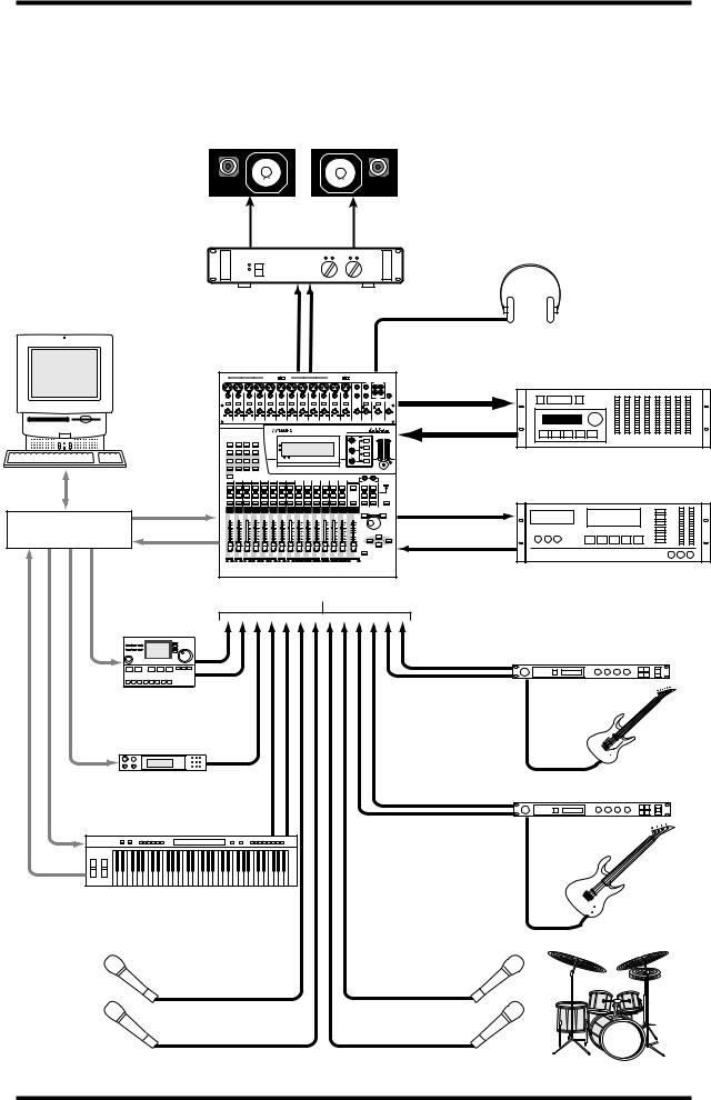
01V System Example
This example shows the kind of system possible with the 01V.
|
|
|
|
|
|
|
|
|
|
|
|
|
|
|
|
|
|
|
Monitors |
|
|
|
|
|
|
|
|
Power Amp |
|
|
|
|
|
|
|
|
|
||||||||
|
|
|
|
|
|
|
|
|
|
|
|
|
|
|
|
|
|
|
|
Headphones |
|
|
Personal computer |
|
|
|
|
|
|
|
|
|
|
|
|
|
|
|
|
|
|
|
|
|
|
running MIDI software |
|
|
|
|
|
|
|
|
|
|
|
|
|
|
|
|
|
|
|
|
|
|
|
MONITOR OUT |
|
|
|
|
|
|
|
|
|
PHONES |
|
|
|
||||||||
|
|
|
|
|
|
|
|
|
|
|
|
|
Digital multitrack |
|||||||||
|
|
|
|
|
PHANTOM +48V |
|
|
|
|
|
|
PHANTOM +48V |
13 |
15 |
L |
|
|
|
||||
|
|
|
|
|
|
|
|
INPUT (BAL) |
|
|
|
|
|
|
|
|
|
|
Digital in |
|
|
|
|
|
|
|
|
|
|
|
|
|
|
|
|
|
|
14 |
16 |
R |
|
|
|
|
|
|
|
|
|
|
|
|
|
|
|
|
|
|
|
|
|
|
2TR |
PHONES |
|
|
|
|
|
PAD |
|
|
|
|
|
|
|
|
|
|
|
|
|
|
|
|
|
|
|
|
|
|
1 |
2 |
3 |
4 |
5 |
|
6 |
7 |
8 |
9 |
|
10 |
11 |
12 |
13/14 |
15/16 |
OUT |
PHONES |
OPTION I/O |
|
|
|
|
|
|
|
|
|
|
|
|
|
|
|
|
|
|
|
|
MONITOR |
|
|
|
|
|
|
|
|
|
|
|
|
|
|
|
|
|
|
|
|
DIGITAL MIXING CONSOLE |
|
|
|
|
|
8-TRACK DIGITAL |
|
|
|
|
|
|
|
|
|
|
|
|
|
|
|
|
EQ HIGH |
L STEREO R |
|
|
|
|||
|
|
|
|
|
|
|
|
|
|
|
|
|
|
|
PAN |
|
|
|
|
|
|
|
|
|
|
|
|
|
|
|
|
|
|
|
|
|
|
|
HI-MID |
|
|
|
Digital out |
|
|
|
|
FADER MODE |
|
|
|
|
|
|
|
|
|
|
|
F |
|
|
|
|
|
|
||
|
|
|
|
|
|
|
|
|
|
|
|
|
|
|
|
LO-MID |
|
|
|
|
|
|
|
|
|
|
|
|
|
|
|
|
|
|
|
|
|
G |
LOW |
|
|
|
|
|
|
Serial port |
171 |
182 |
193 |
204 |
215 |
226 |
237 |
248 |
9 |
10 |
11 |
12 |
13/14 |
15/16 |
MASTER |
1 RETURN 2 |
|
|
|
|
|
|
|
|
|
|
|
|
|
|
|
|
|
|
|
|
|
STEREO |
|
|
|
|
|
|
|
|
SEL SEL SEL |
SEL |
SEL |
SEL |
SEL SEL |
SEL |
SEL |
SEL SEL SEL |
SEL |
SEL |
SEL |
SEL |
SOLO |
|
|
DAT recorder |
||||||
|
ON |
ON |
ON |
ON |
ON |
ON |
ON |
ON |
ON |
ON |
ON |
ON |
ON |
ON |
ON |
ON |
ON |
|
|
Digital in |
||
|
MIDI IN |
|
|
|
|
|
|
|
|
|
|
|
|
|
|
|
|
|
OUT |
|
DAT |
|
MIDI |
|
|
|
|
|
|
|
|
|
|
|
|
|
|
PARAMETER |
|
|
00.00.00.00 |
||||
|
|
|
|
|
|
|
|
|
|
|
|
|
|
|
|
|
|
DIGITAL STEREO |
||||
interface |
|
|
|
|
|
|
|
|
|
|
|
|
|
|
|
|
|
|
|
|
||
|
|
|
|
|
|
|
|
|
|
|
|
|
|
|
|
|
CURSOR |
COAXIAL |
|
|
|
|
|
MIDI OUT |
|
|
|
|
|
|
|
|
|
|
|
|
|
STEREO |
|
|
|
IN |
Digital out |
|
|
|
1 |
2 |
3 |
4 |
5 |
6 |
7 |
8 |
9 |
10 |
11 |
12 |
13/14 |
15/16 |
|
|
|
|
|
|
||
|
17 |
18 |
19 |
20 |
21 |
22 |
23 |
24 |
|
|
|
|
|
|
|
|
|
|
|
|
|
|
|
|
|
|
|
MIC/LINE inputs 1–16 |
|
|
|
|
|
||||||||||||
Drum machine
Guitar processor
MIDI IN 


Tone generator
MIDI IN
Bass processor
MIDI keyboard
MIDI IN
MIDI OUT
Vocals |
Drums |
01V—Owner’s Manual
Important Wordclock Information |
11 |
Important Wordclock Information
Unlike analog audio equipment, digital audio equipment must be wordclock synchronized when digital audio is transferred from one device to another. See “About Wordclocks” on page 206 for more information.
If the 01V is the only digital audio device in your system, no special wordclock settings are required, and the 01V synchronizes to its own internal wordclock. Add a DAT recorder or digital multitrack recorder, however, and the system must be configured so that digital audio equipment synchronizes to a common wordclock source. The “System Examples” on page 241 show how to configure wordclock settings with a variety of digital audio equipment.
Connecting the Power Cord
Warning: Turn off all equipment before making any connections.
Connect the 01V power cord to a suitable AC wall outlet, one that conforms to the power supply requirements stated on the rear panel of the 01V.
Turning On the 01V
Always turn on your audio equipment in the following order:
POWER
 ON/
ON/  OFF
OFF
1.Sound sources
2.01V
3.Monitor amplifier
To turn on the 01V, press the 01V POWER switch located on the rear panel.
When turned on, the 01V startup screen appears for a few seconds, and then the display page selected when the 01V was last turned off appears.
Turning Off the 01V
Always turn off your audio equipment in the following order:
1.Monitor amplifier
2.01V
3.Sound sources
To turn off the 01V, press the 01V POWER switch located on the rear panel.
All parameter settings, scene memories, and library programs are stored when the 01V is turned off.
01V—Owner’s Manual

12 Chapter 2—Getting Started
01V—Owner’s Manual

Touring the 01V |
13 |
Touring the 01V
3
In this chapter...
Top Panel Controls . . . . . . . . . . . . . . . . . . . . . . . . . . . . . . . . . . . . . . . . . . . . . . . . 14
Inputs & Outputs . . . . . . . . . . . . . . . . . . . . . . . . . . . . . . . . . . . . . . . . . . . . . . . . . 20
Block Diagram . . . . . . . . . . . . . . . . . . . . . . . . . . . . . . . . . . . . . . . . . . . . . . . . . . . 24
01V—Owner’s Manual

14 Chapter 3—Touring the 01V
Top Panel Controls
|
|
|
|
|
|
|
PHANTOM +48V OFF ON |
|
|
|
|
|
|
|
|
PHANTOM +48V OFF ON |
|
|
|
|
|
|
|
|
||||||||
|
|
|
|
|
|
|
|
|
|
|
|
INPUT (BAL) |
|
|
|
|
|
|
|
|
|
|
|
|
|
|
|
|
|
|||
|
|
|
|
|
|
|
|
|
|
|
|
|
|
|
|
|
|
|
|
|
|
|
|
|
13 |
|
15 |
|
–10dBV (UNBAL) |
|
||
|
|
|
|
|
|
|
|
|
|
|
|
|
|
|
|
|
|
|
|
|
|
|
|
|
|
|
L |
|
|
|
||
|
|
|
|
|
|
|
|
|
|
|
|
|
|
|
|
|
|
|
|
|
|
|
|
|
|
|
|
|
|
|
|
|
|
|
|
|
|
|
|
|
|
|
|
|
|
|
|
|
|
|
|
|
|
|
|
|
|
14 |
|
16 |
|
R |
|
|
|
|
|
|
|
|
|
|
|
|
|
|
|
|
|
|
|
|
|
|
|
|
|
|
|
|
|
|
|
|
|
|
||
|
|
|
|
|
|
|
|
|
|
|
|
|
|
|
|
|
|
|
|
|
|
|
|
|
|
|
|
|
IN |
OUT |
|
|
|
|
|
|
|
|
|
|
|
|
|
|
|
|
|
|
|
|
|
|
|
|
|
|
|
|
|
|
|
|
2TR |
PHONES |
|
|
|
|
|
|
|
|
|
|
|
|
|
|
|
|
|
|
|
|
|
|
|
|
|
|
|
|
|
|
|
|
||
PAD |
|
|
|
|
|
|
|
|
|
|
|
|
|
|
|
|
|
|
|
|
|
|
|
|
|
|
|
|
|
|
|
|
|
26dB |
|
26dB |
26dB |
|
26dB |
|
26dB |
|
26dB |
26dB |
|
|
26dB |
|
26dB |
26dB |
26dB |
|
|
26dB |
|
|
15/16 |
|
MONITOR |
|
|
||||
|
|
|
|
|
|
|
|
|
|
|
|
|
|
|
|
|
|
|
|
|
|
|
|
|
|
|
2TR IN |
2TR IN |
|
|
||
–16 |
–60 |
–16 |
–60 |
–16 |
–60 |
–16 |
–60 |
–16 |
–60 |
–16 |
–60 |
–16 |
–60 |
–16 |
–60 |
–16 |
–60 |
–16 |
–60 |
–16 |
–60 |
–16 |
–60 |
+10 |
–20 |
+10 |
–20 |
0 |
10 |
0 |
10 |
|
+10 GAIN –34 |
+10 GAIN –34 |
+10 GAIN –34 |
+10 GAIN –34 |
+10 GAIN –34 |
+10 GAIN –34 |
+10 GAIN –34 |
+10 GAIN –34 |
+10 GAIN –34 |
+10 GAIN –34 |
+10 GAIN –34 |
+10 GAIN –34 |
GAIN |
|
GAIN |
|
|
LEVEL |
LEVEL |
|
|||||||||||||
|
1 |
|
2 |
3 |
|
|
4 |
|
5 |
|
6 |
7 |
|
|
8 |
|
9 |
10 |
11 |
|
|
12 |
|
13/14 |
15/16 |
MONITOR |
|
|
||||
|
|
|
|
|
|
|
|
|
|
|
|
|
OUT |
PHONES |
||||||||||||||||||
|
|
|
|
|
|
|
|
|
|
|
|
|
|
|
|
|
|
|
|
|
|
|
|
DIGITAL MIXING CONSOLE |
|
|
|
|
|
|||
|
|
|
|
|
|
|
|
|
|
|
|
|
|
|
|
|
|
|
|
|
|
|
|
|
|
EQ |
HIGH |
|
L STEREO R |
|
||
|
UTILITY |
|
MIDI |
SETUP |
|
VIEW |
|
|
|
|
|
|
|
|
|
|
|
|
|
|
|
|
|
|
PAN |
|
|
|
|
CLIP |
|
|
|
|
|
|
|
|
|
|
|
|
|
|
|
|
|
|
|
|
|
|
|
|
|
|
|
|
|
–3 |
|
||||
|
|
|
|
|
|
|
|
|
|
|
|
|
|
|
|
|
|
|
|
PAN |
|
|
|
|
|
HI-MID |
|
|
–6 |
|
||
|
|
|
|
|
|
|
|
|
FUNCTION |
|
|
|
|
|
|
|
|
|
|
|
|
|
|
|
|
|
–9 |
|
||||
|
|
|
|
|
|
|
|
|
|
|
|
|
|
|
|
|
|
|
|
|
|
|
|
|
|
|
|
|
|
|
||
|
|
|
|
|
|
PAN/ |
|
|
|
|
|
|
|
|
|
|
|
|
|
F |
|
|
|
|
F |
|
|
|
|
|
–12 |
|
|
DYNAMICS |
EQ/ATT |
Ø/DELAY |
|
|
|
|
|
|
|
|
|
|
|
|
|
|
|
|
|
|
|
|
|
|
|
–15 |
|
||||
|
ROUTING |
|
|
MEMORY |
|
|
|
|
|
|
|
|
|
|
G |
|
|
|
|
|
|
LO-MID |
|
|
–18 |
|
||||||
|
|
|
|
|
|
|
|
|
|
|
|
|
|
|
|
|
|
|
|
|
|
|
|
|
|
|
|
–24 |
|
|||
|
|
|
|
|
|
|
|
|
|
|
|
|
|
|
|
|
|
|
|
|
|
|
|
|
|
|
|
|
|
|
–30 |
|
|
|
|
|
|
|
|
|
|
|
|
|
|
|
|
|
|
|
|
|
|
|
|
|
|
|
|
|
|
|
|
–36 |
|
|
|
|
FADER MODE |
|
|
|
|
|
|
|
|
|
|
|
|
|
|
|
|
|
|
|
|
G |
|
LOW |
|
|
|
–42 |
|
|
|
EFFECT 1 |
EFFECT 2 |
OPTION I/O |
REMOTE |
|
|
|
|
1 RETURN 2 |
|
|
|
|
|
|
|
|
|
|
|
|
|
|
|
|
–48 |
|
|||||
|
|
|
|
|
|
|
|
|
|
|
|
|
|
|
|
|
|
|
|
|
|
|
||||||||||
|
|
|
|
|
|
|
|
|
|
|
|
|
|
|
|
|
|
|
|
|
|
|
|
|
|
|
|
|
|
|
||
|
AUX 1 |
AUX 2 |
AUX 3 |
|
AUX 4 |
|
|
|
|
|
|
|
|
|
|
|
|
|
|
|
|
|
|
SELECTED CHANNEL |
|
|
|
|
||||
|
|
|
|
|
|
|
|
|
|
|
|
|
|
|
|
|
|
|
|
|
|
|
|
|
|
|
|
|||||
|
HOME |
|
|
|
|
|
|
|
|
|
|
|
|
|
|
|
|
|
|
|
|
|
|
|
|
|
|
|
|
|
|
|
|
1 |
|
2 |
3 |
|
4 |
5 |
|
6 |
|
7 |
8 |
|
9 |
10 |
|
11 |
|
12 |
13/14 |
|
15/16 |
STEREO |
|
1 RETURN 2 |
|
|
|
||||
|
17 |
|
18 |
19 |
|
20 |
21 |
|
22 |
|
23 |
24 |
|
|
|
|
|
|
|
|
|
|
|
MASTER |
|
|
|
|
|
|
|
|
|
SEL |
|
SEL |
SEL |
|
SEL |
SEL |
|
SEL |
|
SEL |
SEL |
|
SEL |
SEL |
|
SEL |
|
SEL |
SEL |
|
|
SEL |
|
SEL |
|
SEL |
|
SEL |
|
SOLO |
|
|
|
|
|
|
|
|
|
|
|
|
|
|
|
|
|
|
|
|
|
|
|
|
|
|
|
|
|
|
|
|
|
|
|
SOLO |
SOLO |
SOLO |
|
SOLO |
SOLO |
|
SOLO |
|
SOLO |
SOLO |
|
SOLO |
SOLO |
|
SOLO |
|
SOLO |
SOLO |
|
|
SOLO |
|
|
|
SOLO |
|
SOLO |
|
|
|
|
|
ON |
|
ON |
ON |
|
ON |
ON |
|
ON |
|
ON |
ON |
|
ON |
ON |
|
ON |
|
ON |
ON |
|
|
ON |
|
ON |
|
ON |
|
ON |
|
MEMORY |
|
|
|
|
|
|
|
|
|
|
|
|
|
|
|
|
|
|
|
|
|
|
|
|
|
|
|
–1/DEC |
|
|
+1/INC |
|
||
|
|
|
|
|
|
|
|
|
|
|
|
|
|
|
|
|
|
|
|
|
|
|
|
|
|
|
|
PARAMETER |
|
|
||
|
6 |
6 |
|
6 |
6 |
|
6 |
|
6 |
6 |
|
6 |
6 |
|
6 |
|
6 |
6 |
|
6 |
|
6 |
|
0 |
|
|
|
|
|
|
|
|
|
|
|
|
|
|
|
|
|
|
|
|
|
|
|
|
|
|
|
|
|
|
|
|
–5 |
|
|
|
|
|
|
|
|
|
0 |
0 |
|
0 |
0 |
|
0 |
|
0 |
0 |
|
0 |
0 |
|
0 |
|
0 |
0 |
|
0 |
|
0 |
|
–10 |
|
|
|
|
|
|
|
|
|
5 |
5 |
|
5 |
5 |
|
5 |
|
5 |
5 |
|
5 |
5 |
|
5 |
|
5 |
5 |
|
5 |
|
5 |
|
–15 |
|
|
|
|
|
|
|
|
|
|
|
|
|
|
|
|
|
|
–20 |
|
|
|
|
|
|
|
|
||||||||||||||
|
|
|
|
|
|
|
|
|
|
|
|
|
|
|
|
|
|
|
|
|
|
|
|
|
|
|
|
|
|
|
|
|
|
10 |
10 |
|
10 |
10 |
|
10 |
|
10 |
10 |
|
10 |
10 |
|
10 |
|
10 |
10 |
|
10 |
|
10 |
|
|
|
|
|
|
|
|
CURSOR |
|
|
|
|
|
|
|
|
|
|
|
–30 |
|
|
|
|
|
|
|
|
||||||||||||||
|
|
|
|
|
|
|
|
|
|
|
|
|
|
|
|
|
|
|
|
|
|
|
|
|
|
|
|
|
|
|
|
|
|
20 |
20 |
|
20 |
20 |
|
20 |
|
20 |
20 |
|
20 |
20 |
|
20 |
|
20 |
20 |
|
20 |
|
20 |
|
–40 |
|
|
|
|
|
|
|
|
|
40 |
40 |
|
40 |
40 |
|
40 |
|
40 |
40 |
|
40 |
40 |
|
40 |
|
40 |
40 |
|
40 |
|
40 |
|
–50 |
|
|
|
|
|
|
|
|
|
|
|
|
|
|
|
|
|
|
–70 |
|
|
|
|
|
|
|
|
||||||||||||||
|
60 |
60 |
|
60 |
60 |
|
60 |
|
60 |
60 |
|
60 |
60 |
|
60 |
|
60 |
60 |
|
60 |
|
60 |
|
|
|
|
|
|
|
|
|
|
|
∞ |
∞ |
|
∞ |
∞ |
|
∞ |
|
∞ |
∞ |
|
∞ |
∞ |
|
∞ |
|
∞ |
∞ |
|
∞ |
|
∞ |
|
– ∞ |
|
|
|
|
|
|
|
|
|
|
|
|
|
|
|
|
|
|
|
|
|
|
|
|
|
|
|
|
|
|
|
|
|
|
ENTER |
|
|
|
|
|
|
|
1 |
|
2 |
3 |
|
4 |
5 |
|
6 |
|
7 |
8 |
|
9 |
10 |
|
11 |
|
12 |
13/14 |
|
15/16 |
STEREO |
|
|
|
|
|
|
|
||
|
17 |
|
18 |
19 |
|
20 |
21 |
|
22 |
|
23 |
24 |
|
|
|
|
|
|
|
|
|
|
|
MASTER |
|
|
|
|
|
|
|
|
The individual sections of the 01V are explained on the following pages.
01V—Owner’s Manual

Top Panel Controls |
15 |
Analog Control Section
|
|
|
|
|
|
|
|
|
|
|
1 |
|
|
|
|
|
|
|
|
|
|
|
|
|
2 |
3 |
|
|
|||
PAD |
|
|
|
|
|
|
|
|
|
|
|
|
|
|
|
|
|
|
|
|
|
|
|
|
|
|
|
|
|
|
|
|
26dB |
|
26dB |
|
26dB |
|
26dB |
|
26dB |
|
26dB |
|
26dB |
|
26dB |
|
26dB |
|
26dB |
|
26dB |
|
26dB |
|
|
|
15/16 |
MONITOR |
|
|
|
|
|
|
|
|
|
|
|
|
|
|
|
|
|
|
|
|
|
|
|
|
|
|
|
|
|
|
2TR IN |
2TR IN |
|
|
|
–16 |
–60 |
–16 |
–60 |
–16 |
–60 |
–16 |
–60 |
–16 |
–60 |
–16 |
–60 |
–16 |
–60 |
–16 |
–60 |
–16 |
–60 |
–16 |
–60 |
–16 |
–60 |
–16 |
–60 |
+10 |
–20 |
+10 |
–20 |
+10 |
–20 |
+10 |
–20 |
+10 GAIN –34 |
+10 GAIN –34 |
+10 GAIN –34 |
+10 GAIN –34 |
+10 GAIN –34 |
+10 GAIN –34 |
+10 GAIN –34 |
+10 GAIN –34 |
+10 GAIN –34 |
+10 GAIN –34 |
+10 GAIN –34 |
+10 GAIN –34 |
|
GAIN |
|
GAIN |
LEVEL |
LEVEL |
||||||||||||||
|
1 |
|
2 |
|
3 |
|
4 |
|
5 |
|
6 |
|
7 |
|
8 |
|
9 |
|
10 |
|
11 |
|
12 |
13/14 |
15/16 |
MONITOR |
|
|
|||
|
|
|
|
|
|
|
|
|
|
|
|
OUT |
|
PHONES |
|||||||||||||||||
|
|
|
|
|
|
|
|
|
|
|
|
|
4 |
|
|
|
|
|
|
|
|
|
|
|
|
|
5 |
6 |
|||
APAD switches
These switches are used to turn on and off the 26 dB input pads. See “Pad Switches” on page 41 for more information.
B15/16–2TR IN Switch
This switch is used to select the signal source for input channels 15 and 16: phone jacks 15 and 16 (15/16) or the 2TR IN phono jacks (2TR IN).
CMONITOR–2TR IN Switch
This switch is used to select the signal source for the monitor out and phones: Monitor bus (MONITOR) or 2TR IN phono jacks (2TR IN).
DGAIN controls
These controls are used to adjust the gain of the input preamps. See “Setting Input Channel Gain” on page 41 for more information.
EMONITOR OUT LEVEL control
This control is used to adjust the monitor out level.
FPHONES LEVEL control
This control is used to adjust the phones level.
01V—Owner’s Manual

16 Chapter 3—Touring the 01V
Display, Selected Channel Controls & Meters
DIGITAL MIXING CONSOLE 


|
|
|
EQ |
HIGH |
L STEREO R |
|
|
|
|
PAN |
|
CLIP |
|
|
|
|
|
|
–3 |
|
|
|
PAN |
|
HI-MID |
–6 |
|
FUNCTION |
|
|
–9 |
|
||
|
|
|
|
|||
|
1 |
F |
F |
|
–12 |
|
MEMORY |
|
–15 |
4 |
|||
|
G |
|
LO-MID |
–18 |
||
|
|
|
–24 |
|||
|
|
|
|
|
–30 |
|
|
|
|
|
|
–36 |
|
|
|
|
G |
|
–42 |
|
|
1 RETURN 2 |
|
LOW |
–48 |
|
|
|
|
|
|
|||
|
|
|
|
|
|
SELECTED CHANNEL
2 3
ADisplay
This 320 x 80 dot LCD display provides clear indication of mix settings and operating status. As well as showing parameter values numerically, faders and rotary controls are represented graphically, so you can actually see pan and fader positions. The display also shows EQ curves and signal level meters. See “Display” on page 28 for more information.
BSELECTED CHANNEL Controls
These controls are used to adjust the pan and EQ of the selected channel. Dedicated rotary controls for PAN, EQ frequency (F) and EQ gain (G), and EQ [HIGH], [HI-MID], [LO-MID], and [LOW] buttons make for quick operation. When the EQ AUTO SCREEN option is turned on, and an EQ control is adjusted, the EQ page appears automatically. Likewise, for the PANPOT AUTO SCREEN option and PAN control. See “Setting 01V Preferences” on page 203 for more information.
CContrast
This control is used to adjust the display contrast. Adjust it so that the display is clear and easy-to-read from your viewing position.You may need to readjust it when viewing the display from a different height or angle.
DStereo Output Meters
These 12-segment LED bar-type meters display the stereo output signal levels.
Parameter Wheel, Cursors & Enter
–1/DEC |
+1/INC |
PARAMETER
CURSOR
ENTER
These controls are used to navigate around the display pages and edit parameters. See “Getting Around the User Interface” on page 27 for more information.
01V—Owner’s Manual
Top Panel Controls |
17 |
Function Buttons
UTILITY |
MIDI |
SETUP |
VIEW |
MEMORY
PAN/
DYNAMICS EQ/ATT Ø/DELAY ROUTING
Function buttons are used to access the following function pages. Related pages are grouped together and can be selected by repeatedly pressing a button. The name of the selected function and its page number appear in the top-left corner of the display.
Button |
Pages |
|
|
UTILITY |
Oscillator, Preferences-1, Preferences-2 |
|
|
MIDI |
MIDI Setup, Program Change, Control Change, Bulk, Local Control |
|
|
SETUP |
Word Clock Select, Monitor/Solo Setup, Group, Pair, Dither |
|
|
VIEW |
Channel View, Fader View, CH Copy |
|
|
DYNAMICS |
Dynamics Edit, Dynamics Library |
|
|
EQ/ATT |
EQ Edit, EQ Library |
|
|
ø/DELAY |
Phase, Input Delay 1–8, Input Delay 9–16, Output Delay |
|
|
PAN/ROUTING |
Panpot, Routing, Bus Master, Omni Out Select |
|
|
MEMORY |
Memory, Fade Time, Memory Sort, Recall Safe |
|
|
Fader Mode Buttons
FADER MODE
EFFECT 1 |
EFFECT 2 |
OPTION I/O |
REMOTE |
AUX 1 |
AUX 2 |
AUX 3 |
AUX 4 |
HOME |
|
|
|
Fader mode buttons are used to select the following fader modes and display pages. Pressing buttons repeatedly selects the various pages that are available for a mode. The name of the selected function and its page number appear in the top-left corner of the display.
Button |
Pages |
|
|
|
|
EFFECT 1 |
Effect1 Edit, Effect1 Library, Effect1 Pre/Post |
|
|
|
|
EFFECT 2 |
Effect2 Edit, Effect2 Library, Effect2 Pre/Post |
|
|
|
|
OPTION I/O |
Option In Meter, Channel Control, Option Out Meter, Option Out |
|
Select, Input Swap |
||
|
||
|
|
|
REMOTE |
Internal Parameter, MMC Control, User Define |
|
|
|
|
AUX 1 |
Pre/Post, Aux 1-2 Pan |
|
|
|
|
AUX 2 |
Pre/Post, Aux 1-2 Pan |
|
|
|
|
AUX 3 |
Pre/Post, Aux 3-4 Pan |
|
|
|
|
AUX 4 |
Pre/Post, Aux 3-4 Pan |
|
|
|
|
HOME |
Input Meter, Rtn/Output Meter, Omni Out Meter, St Out Meter, |
|
Metering Point |
||
|
||
|
|
01V—Owner’s Manual
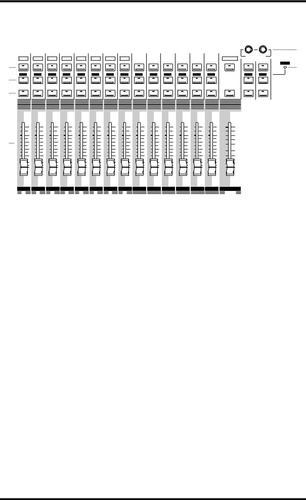
18 Chapter 3—Touring the 01V
SEL, SOLO, ON buttons & Faders
1
2
3
5
1 |
2 |
3 |
4 |
5 |
6 |
7 |
8 |
9 |
10 |
11 |
12 |
13/14 |
15/16 |
STEREO |
1 RETURN 2 |
|
|
17 |
18 |
19 |
20 |
21 |
22 |
23 |
24 |
|
|
|
|
|
|
MASTER |
|
|
|
SEL |
SEL |
SEL |
SEL |
SEL |
SEL |
SEL |
SEL |
SEL |
SEL |
SEL |
SEL |
SEL |
SEL |
SEL |
SEL |
SEL |
SOLO 6 |
|
|
|
|
|
|
|
|
|
|
|
|
|
|
|
|
|
|
SOLO |
SOLO |
SOLO |
SOLO |
SOLO |
SOLO |
SOLO |
SOLO |
SOLO |
SOLO |
SOLO |
SOLO |
SOLO |
SOLO |
|
SOLO |
SOLO |
|
ON |
ON |
ON |
ON |
ON |
ON |
ON |
ON |
ON |
ON |
ON |
ON |
ON |
ON |
ON |
ON |
ON |
|
|
6 |
6 |
6 |
6 |
6 |
6 |
6 |
6 |
6 |
6 |
6 |
6 |
6 |
6 |
0 |
|
|
|
|
|
|
|
|
|
|
|
|
|
|
|
|
–5 |
|
|
0 |
0 |
0 |
0 |
0 |
0 |
0 |
0 |
0 |
0 |
0 |
0 |
0 |
0 |
–10 |
|
4 |
5 |
5 |
5 |
5 |
5 |
5 |
5 |
5 |
5 |
5 |
5 |
5 |
5 |
5 |
–15 |
|
–20 |
||||||||||||||||
|
|
|
|
|
|
|
|
|
|
|
|
|
|
|
||
|
10 |
10 |
10 |
10 |
10 |
10 |
10 |
10 |
10 |
10 |
10 |
10 |
10 |
10 |
–30 |
|
|
|
|
|
|
|
|
|
|
|
|
|
|
|
|
||
|
20 |
20 |
20 |
20 |
20 |
20 |
20 |
20 |
20 |
20 |
20 |
20 |
20 |
20 |
–40 |
|
|
40 |
40 |
40 |
40 |
40 |
40 |
40 |
40 |
40 |
40 |
40 |
40 |
40 |
40 |
–50 |
|
|
–70 |
|||||||||||||||
|
60 |
60 |
60 |
60 |
60 |
60 |
60 |
60 |
60 |
60 |
60 |
60 |
60 |
60 |
||
|
∞ |
∞ |
∞ |
∞ |
∞ |
∞ |
∞ |
∞ |
∞ |
∞ |
∞ |
∞ |
∞ |
∞ |
– ∞ |
|
|
1 |
2 |
3 |
4 |
5 |
6 |
7 |
8 |
9 |
10 |
11 |
12 |
13/14 |
15/16 |
STEREO |
|
|
17 |
18 |
19 |
20 |
21 |
22 |
23 |
24 |
|
|
|
|
|
|
MASTER |
ASEL buttons
The [SEL] buttons are used to select channels for parameter editing: input channels 1 through 24, effects returns 1 and 2, aux sends 1 through 4, effects sends 1 and 2, and the stereo output. Press [SEL] button 13/14 or 15/16 repeatedly to select input channels 13 and 14 or 15 and 16, respectively. Since most functions on input channels 13 and 14 (likewise 15 and 16) are linked together, the only time you’ll need to select either channel 13 or channel 14 (likewise 15 or 16) is to set the Phase or Pan for a channel individually. The number of the selected channel appears in the lower-right corner of the display. See “Display” on page 28 for more information.
Normally, [SEL] buttons 1 through 8 select channels 1 through 8. When the [OPTION I/O] button is pressed, however, they select input channels 17 through 24, which are only available when an Option I/O card is installed. See “SEL Buttons” on page 32 for more information. The [SEL] buttons 1 through 6 are also used to transmit MMC (MIDI Machine Control) Locate commands when REMOTE page 2 is displayed. Finally, [SEL] buttons are also used to make and break channel pairs (“Pairing Input Channels” on page 52) and fader and mute groups (“Grouping Faders” on page 55 and “Grouping Mutes” on page 56).
BSOLO buttons
The [SOLO] buttons are used to solo channels: input channels 1 through 16 and effects returns 1 and 2. Normally, [SOLO] buttons 1 through 8 select channels 1 through 8. When the [OPTION I/O] button is pressed, however, they select input channels 17 through 24, which are only available when an Option I/O card is installed. See “Solo Buttons” on page 33 for more information.
The [SOLO] buttons 1 through 16 can also be used as MIDI controllers on REMOTE page 3. See “User Defined MIDI Controllers” on page 238 for more information.
CON buttons
The [ON] buttons are used to turn channels on and off: input channels 1 through 24, effects returns 1 and 2, aux sends 1 through 4, effects sends 1 and 2, and the stereo out-
01V—Owner’s Manual

Top Panel Controls |
19 |
put. Normally, [ON] buttons 1 through 8 select channels 1 through 8. When the [OPTION I/O] button is pressed, however, they select input channels 17 through 24, which are only available when an Option I/O card is installed. See “ON Buttons” on page 34 for more information.
The [ON] buttons 1 through 16 and master can be assigned to various internal parameters on REMOTE page 1, or used as MIDI controllers on REMOTE page 3. See “Assigning Faders & On Buttons” on page 194 and “User Defined MIDI Controllers” on page 238 for more information.
DFaders
Depending on the selected fader mode, the 01V’s 60 mm motorized faders are used to control channel levels, aux send levels, or effects sends levels. Normally, faders 1 through 8 control channels 1 through 8. When the [OPTION I/O] button is pressed, however, they control input channels 17 through 24, which are only available when an Option I/O card is installed. See “Faders (plus Return Rotary Controls)” on page 35 for more information.
Faders 1 through 16 and master can be assigned to various internal parameters on REMOTE page 1, or used as MIDI controllers on REMOTE page 3. See “Assigning Faders & On Buttons” on page 194 and “User Defined MIDI Controllers” on page 238 for more information.
ERETURN Controls
The RETURN controls are used to adjust the effects return levels, and their positions are displayed in the lower-left corner of the display.
FSOLO Status Indicator
The SOLO status indicator lights up when a channel is soloed.
01V—Owner’s Manual
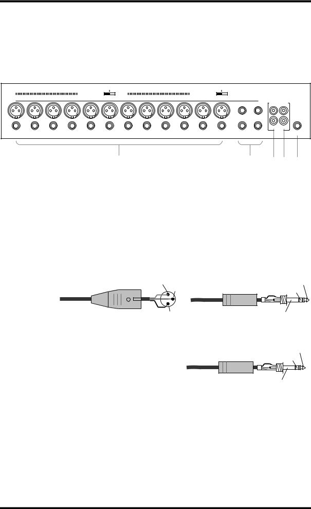
20 Chapter 3—Touring the 01V
Inputs & Outputs
Input and output connectors are located on the top and rear panels.
Top Panel
PHANTOM +48V OFF ON |
PHANTOM +48V OFF ON |
|
|
|
|
INPUT (BAL) |
|
|
|
|
13 |
15 |
–10dBV (UNBAL) |
|
|
L |
|
||
|
|
|
|
|
|
14 |
16 |
R |
|
|
|
|
||
|
|
|
IN |
OUT |
|
|
|
|
2TR |
|
|
|
|
PHONES |
|
1 |
2 |
34 5 |
|
AINPUT (BAL) 1–12
Input channels 1 through 12 feature balanced XLR-3-31-type and balanced phone jack connectors, both with a nominal input range of –60 dB to +10 dB. Phantom powering (+48 V) is supplied to the XLR connectors, with master on/off switches for connectors 1 through 6 and 7 through 12. Phone jacks, which can also be used with unbalanced phone plugs, have priority over the XLR-type connectors, so when a phone plug is inserted, the XLR-type connector is disconnected.With their high sensitivity and 26 dB PAD switches, these inputs can handle a wide range of signals, from condenser microphones to “hot” line levels.
1 (ground)
Male XLR plug
3 (cold)
2 (hot)
BINPUT (BAL) 13–16
Input channels 13 through 16 feature balanced phone jack connectors, with a nominal input range of –20 dB to +10 dB. These inputs are designed for use with line-level sources, and can also be used with unbalanced phone plugs. The stereo outputs of an external effects processor or other stereo device can be connected here.
|
Tip (hot) |
1/4" TRS phone plug |
Ring (cold) |
|
Sleeve (ground) |
|
Tip (hot) |
1/4" TRS phone plug |
Ring (cold) |
|
Sleeve (ground) |
01V—Owner’s Manual
Loading...