


Yale GP80VX, GLP80VX, GDP80VX, GP90VX, GLP90VX Repair Manual
...GP/GLP/GDP80VX, GP/GLP/GDP90VX, GP/GLP/GDP100VX, GP/GLP/
GDP110VX, GP/GLP/GDP120VX (J813)
SERVICE MANUAL CONTENTS
SECTION |
PART |
YRM |
REV |
NUMBER |
NUMBER |
DATE |
|
FRAME............................................................................................................................ |
524262274 |
0100 YRM 1243 |
05/14 |
OPERATOR'S CAB........................................................................................................ |
524306203 |
0100 YRM 1290 |
04/14 |
GM 4.3L V-6 ENGINES................................................................................................... |
524265337 |
0600 YRM 1251 |
05/14 |
KUBOTA ENGINE REPAIR............................................................................................ |
550048607 |
0600 YRM 1557 |
03/13 |
KUBOTA DIESEL 3.6L ENGINE.................................................................................... |
550055279 |
0600 YRM 1579 |
01/14 |
COOLING SYSTEM........................................................................................................ |
524223757 |
0700 YRM 1123 |
03/13 |
LPG FUEL SYSTEM GM 4.3L ENGINE WITH PSI........................................................ |
550043871 |
0900 YRM 1556 |
04/14 |
GASOLINE FUEL SYSTEM............................................................................................ |
550048401 |
0900 YRM 1570 |
09/13 |
1 AND 2 SP PS TRANSMISSION REPAIR.................................................................... |
550048681 |
1300 YRM 1569 |
08/13 |
DRIVE AXLE AND DIFFERENTIAL ASSEMBLY REPAIR............................................ |
524262278 |
1400 YRM 1246 |
12/13 |
DRIVE AXLE AND DIFFERENTIAL ASSEMBLY REPAIR............................................ |
550055280 |
1400 YRM 1582 |
12/13 |
STEERING AXLE............................................................................................................ |
524223764 |
1600 YRM 1133 |
07/13 |
WET BRAKES - NMHG.................................................................................................. |
550064329 |
1800 YRM 1597 |
12/13 |
HYDRAULIC GEAR PUMP............................................................................................. |
524223766 |
1900 YRM 1136 |
04/14 |
HYDRAULIC CLEANLINESS PROCEDURES............................................................... |
550073240 |
1900 YRM 1620 |
12/14 |
MAIN CONTROL VALVE................................................................................................ |
524223767 |
2000 YRM 1137 |
04/14 |
CYLINDER REPAIR (MAST S/N A551, A555, A559, A661, A662, A663, A66, B507, |
|
|
|
B508, B509, B551, B555, B559, B562, B563, B564, B661, B662, B663, C515, |
|
|
|
C551, C555, C559, D507, D508, D509, D515, D562, D563, D564, E509, AND |
524223768 |
2100 YRM 1139 |
02/14 |
E564).......................................................................................................................... |
|||
HIGH VOLTAGE SWITCH (HVS) IGNITION.................................................................. |
524208014 |
2200 YRM 1097 |
05/14 |
WIRE HARNESS REPAIR.............................................................................................. |
524223769 |
2200 YRM 1128 |
12/14 |
USER INTERFACE......................................................................................................... |
524223770 |
2200 YRM 1130 |
12/14 |
USER INTERFACE......................................................................................................... |
524223771 |
2200 YRM 1131 |
12/14 |
ELECTRICAL SYSTEM.................................................................................................. |
524223772 |
2200 YRM 1142 |
04/14 |
MAST REPAIRS (S/N A513, A514, A613, A614, A702, A703, A704, A705, A706, |
|
|
|
A707, A751, A752, B513, B514, B586, B587, B588, B589, B590, B591, B749, |
524265342 |
4000 YRM 1250 |
02/14 |
B750, B751, B752, B753, B754)................................................................................ |
|||
METRIC AND INCH (SAE) FASTENERS....................................................................... |
524150797 |
8000 YRM 0231 |
10/13 |
CALIBRATION PROCEDURES...................................................................................... |
524223780 |
8000 YRM 1134 |
12/14 |
DIAGRAMS AND SCHEMATICS.................................................................................... |
550055283 |
8000 YRM 1585 |
04/14 |
PERIODIC MAINTENANCE............................................................................................ |
550068685 |
8000 YRM 1604 |
12/13 |
CAPACITIES AND SPECIFICATIONS........................................................................... |
550068693 |
8000 YRM 1605 |
07/14 |
DIAGRAMS AND SCHEMATICS.................................................................................... |
550096331 |
8000 YRM 1689 |
04/14 |
DIAGNOSTIC TROUBLESHOOTING MANUAL............................................................ |
524221866 |
9000 YRM 1112 |
12/14 |
9000 YRM 1112 ON CD
PART NO. 550069027 (12/14)

SAFETY PRECAUTIONS
MAINTENANCE AND REPAIR
•The Service Manuals are updated on a regular basis, but may not reflect recent design changes to the product. Updated technical service information may be available from your local authorized Yale® dealer. Service Manuals provide general guidelines for maintenance and service and are intended for use by trained and experienced technicians. Failure to properly maintain equipment or to follow instructions contained in the Service Manual could result in damage to the products, personal injury, property damage or death.
•When lifting parts or assemblies, make sure all slings, chains, or cables are correctly fastened, and that the load being lifted is balanced. Make sure the crane, cables, and chains have the capacity to support the weight of the load.
•Do not lift heavy parts by hand, use a lifting mechanism.
•Wear safety glasses.
•DISCONNECT THE BATTERY CONNECTOR before doing any maintenance or repair on electric lift trucks. Disconnect the battery ground cable on internal combustion lift trucks.
•Always use correct blocks to prevent the unit from rolling or falling. See HOW TO PUT THE LIFT TRUCK ON BLOCKS in the Operating Manual or the Periodic Maintenance section.
•Keep the unit clean and the working area clean and orderly.
•Use the correct tools for the job.
•Keep the tools clean and in good condition.
•Always use YALE APPROVED parts when making repairs. Replacement parts must meet or exceed the specifications of the original equipment manufacturer.
•Make sure all nuts, bolts, snap rings, and other fastening devices are removed before using force to remove parts.
•Always fasten a DO NOT OPERATE tag to the controls of the unit when making repairs, or if the unit needs repairs.
•Be sure to follow the WARNING and CAUTION notes in the instructions.
•Gasoline, Liquid Petroleum Gas (LPG), Compressed Natural Gas (CNG), and Diesel fuel are flammable. Be sure to follow the necessary safety precautions when handling these fuels and when working on these fuel systems.
•Batteries generate flammable gas when they are being charged. Keep fire and sparks away from the area. Make sure the area is well ventilated.
NOTE: The following symbols and words indicate safety information in this manual:
WARNING
Indicates a hazardous situation which, if not avoided, could result in death or serious injury.
CAUTION
Indicates a hazardous situation which, if not avoided, could result in minor or moderate injury and property damage.
On the lift truck, the WARNING symbol and word are on orange background. The CAUTION symbol and word are on yellow background.
Table of Contents |
|
TABLE OF CONTENTS |
|
General ..................................................................................................................................................................... |
1 |
Description ................................................................................................................................................................ |
2 |
Hood, Seat, and Side Covers Replacement ............................................................................................................. |
4 |
Remove ................................................................................................................................................................ |
4 |
Install .................................................................................................................................................................... |
4 |
Steering Column ..................................................................................................................................................... |
12 |
Description .......................................................................................................................................................... |
12 |
Steering Column Repair ..................................................................................................................................... |
12 |
Remove .......................................................................................................................................................... |
12 |
Disassemble ................................................................................................................................................... |
13 |
Clean .............................................................................................................................................................. |
16 |
Inspect ............................................................................................................................................................ |
16 |
Assemble ....................................................................................................................................................... |
16 |
Install .............................................................................................................................................................. |
16 |
LPG Tank and Bracket Replacement ..................................................................................................................... |
17 |
Counterweight Replacement .................................................................................................................................. |
17 |
Remove .............................................................................................................................................................. |
17 |
Install .................................................................................................................................................................. |
20 |
Tow Pin ............................................................................................................................................................... |
24 |
Remove and Install For Lift Truck Models GLP/GDP40VX5/VX6; GLP/GDP45SVX5, GLP/ |
|
GDP45VX6; GLP/GDP50-55VX (GP/GLP/GDP080, 090, 100, 110, 120VX) (F813, G813, H813)................ |
24 |
Remove and Install For Lift Truck Models GLC55SVX (GC/GLC80XVBCS, GC/ |
|
GLC100VXBCS; GC/GLC120SVX; and GC/GLC120VXPRS) (E818, F818) and GLP/ |
|
GDP40VX5/VX6; GLP/GDP45SVX5, GLP/GDP45VX6; GLP/GDP50-55VX (GP/GLP/ |
|
GDP080, 090, 100, 110, 120VX) (J813)......................................................................................................... |
24 |
Overhead Guard Replacement ............................................................................................................................... |
25 |
Remove .............................................................................................................................................................. |
25 |
Install .................................................................................................................................................................. |
25 |
LED Tail, Backup, and Brake Lights, Replace .................................................................................................... |
26 |
Operator Restraint System Replacement ............................................................................................................... |
26 |
Description .......................................................................................................................................................... |
26 |
Engine Replacement .............................................................................................................................................. |
28 |
Remove Engine Only .......................................................................................................................................... |
28 |
Install Engine only .............................................................................................................................................. |
56 |
Remove Engine and Transmission ..................................................................................................................... |
60 |
Install Engine and Transmission ......................................................................................................................... |
65 |
Electronic Throttle Replacement ............................................................................................................................. |
69 |
Cummins 4.5L Diesel Engine With Electronic Throttle ....................................................................................... |
69 |
Remove .......................................................................................................................................................... |
69 |
Install .............................................................................................................................................................. |
69 |
Pull Actuator Linkage Adjustment .................................................................................................................. |
74 |
Low Idle Adjustment ....................................................................................................................................... |
75 |
Throttle Pedal and Cable Adjustment ..................................................................................................................... |
75 |
Cummins 4.5L Diesel Engine with Basic Power Shift Transmission .................................................................. |
75 |
Kubota 3.6L Diesel Engine ................................................................................................................................. |
75 |
Exhaust System Repair .......................................................................................................................................... |
78 |
GM 4.3L Engine for Lift Truck Models and GLC40, 45, 55VX; GLC55SVX; (GC/GLC080, 100, |
|
120VX; GC/GLC080, 100VXBCS; GC/GLC120SVX; GC/GLC120VXPRS) (E818, F818).................................. |
78 |
Cummins 4.5L Diesel Engine for Lift Truck Models GLP/GDP40VX5/VX6; GLP/GDP45SVX5, |
|
GLP/GDP45VX6; GLP/GDP50-55VX (GP/GLP/GDP080, 090, 100, 110, 120VX) (F813).................................. |
78 |
©2014 Yale Materials Handling Corp. |
i |

Table of Contents |
|
|
TABLE OF CONTENTS (Continued) |
|
|
Remove .......................................................................................................................................................... |
|
78 |
Inspect ............................................................................................................................................................ |
|
78 |
Install .............................................................................................................................................................. |
|
78 |
Cummins QSB 3.3L Engine for Lift Truck Models GLP/GDP40VX5/VX6; GLP/GDP45SVX5, |
|
|
GLP/GDP45VX6; GLP/GDP50-55VX (GP/GLP/GDP080, 090, 100, 110, 120VX) (G813)................................. |
80 |
|
Remove .......................................................................................................................................................... |
|
80 |
Inspect ............................................................................................................................................................ |
|
82 |
Install .............................................................................................................................................................. |
|
82 |
Kubota Diesel Engine for Lift Truck Models and Equipped with Kubota 3.6L Diesel Engine |
|
|
GLP/GDP40VX5/VX6; GLP/GDP45SVX5, GLP/GDP45VX6; GLP/GDP50-55VX (GP/GLP/ |
|
|
GDP080, 090, 100, 110, 120VX) (H813)............................................................................................................. |
|
82 |
Remove .......................................................................................................................................................... |
|
82 |
Inspect ............................................................................................................................................................ |
|
84 |
Install .............................................................................................................................................................. |
|
84 |
Kubota Diesel Engine for Lift Truck Models GLP/GDP40VX5/VX6; GLP/GDP45SVX5, GLP/ |
|
|
GDP45VX6; GLP/GDP50-55VX (GP/GLP/GDP080, 090, 100, 110, 120VX) (J813).......................................... |
84 |
|
Remove .......................................................................................................................................................... |
|
84 |
Inspect ............................................................................................................................................................ |
|
87 |
Diesel Particulate Filter .................................................................................................................................. |
|
89 |
Disassemble .............................................................................................................................................. |
|
89 |
CLEAN AND INSPECT .............................................................................................................................. |
|
90 |
Assembly ................................................................................................................................................... |
|
91 |
Install .............................................................................................................................................................. |
|
91 |
Cooling System ....................................................................................................................................................... |
|
92 |
Description .......................................................................................................................................................... |
|
92 |
Hydraulic Filter Assembly Repair ............................................................................................................................ |
|
93 |
Remove .............................................................................................................................................................. |
|
93 |
Disassemble ....................................................................................................................................................... |
|
93 |
Clean .................................................................................................................................................................. |
|
94 |
Inspect ................................................................................................................................................................ |
|
94 |
Assemble ............................................................................................................................................................ |
|
94 |
Install .................................................................................................................................................................. |
|
94 |
Fuel and Hydraulic Tanks Repair ........................................................................................................................... |
|
94 |
Inspect ................................................................................................................................................................ |
|
94 |
Clean .................................................................................................................................................................. |
|
95 |
Steam Method of Cleaning ............................................................................................................................. |
|
95 |
Chemical Solution Method of Cleaning .......................................................................................................... |
|
96 |
Additional Preparations for Repair ...................................................................................................................... |
|
96 |
Small Leaks, Repair ........................................................................................................................................... |
|
96 |
Large Leaks, Repair ........................................................................................................................................... |
|
96 |
Preparations for Use After Repair ...................................................................................................................... |
|
96 |
Safety Labels .......................................................................................................................................................... |
|
97 |
This section is for the following models: |
|
|
GLC40, 45, 55VX; GLC55SVX (GC/GLC080, 100, 120VX; GC/GLC080, |
|
|
100VXBCS; GC/GLC120SVX; GC/GLC120VXPRS) [E818, F818]; |
|
|
GLP/GDP40VX5/VX6; GLP/GDP45SVX5, GLP/GDP45VX6; GLP/GDP50-55VX |
|
|
(GP/GLP/GDP080, 090, 100, 110, 120VX) |
[F813, G813, H813, J813] |
|
ii

0100 YRM 1243 |
General |
General
WARNING
The lift truck must be put on blocks for some types of maintenance and repairs. The removal of the following assemblies will cause large changes in the center of gravity: mast, drive axle, engine and transmission, and counterweight. When the lift truck is put on blocks, put additional blocks in the following positions to maintain stability:
•Before removing the mast and drive axle, put blocks under the counterweight so the lift truck cannot fall backward.
•Before removing the counterweight, put blocks under the mast assembly so the lift truck cannot fall forward.
The surface must be solid, even, and level when the lift truck is put on blocks. Make sure any blocks used to support the lift truck are solid, one-piece units. See the procedure How to Put Lift Truck on Blocks in the Operating Manual or the Periodic Maintenance section for your lift truck.
If additional engine repairs are necessary for lift trucks covered in this manual see:
•GM 4.3L V-6 Engines 0600YRM1251
•Kubota Diesel 3.8L Engines 0600YRM1557
•Kubota Diesel 3.6L Engine 0600YRM1579
If additional transmission repairs are necessary for lift trucks covered in this manual see:
•Powershift Transmission 1300YRM1129
•Powershift Transmission 1300YRM1529
•One and Two Speed Transmissions
1300YRM1569
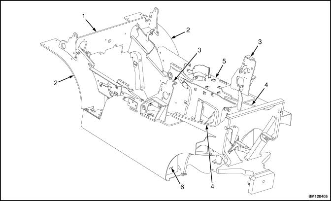
This section contains the description of the frame (see Figure 1 or Figure 2) and connected parts. Procedures for removing and installing the counterweight, hood, overhead guard, engine and transmission, and exhaust system are found in this section. Checks for the operator restraint system and procedures for the repair of tanks and installation of safety labels are also included.
1
Description |
0100 YRM 1243 |
Description
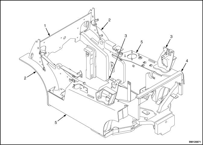
The frame is one weldment and includes the hydraulic tank and fuel tank for gasoline or diesel fuel. See Figure 1 or Figure 2.
There is a counterweight for each capacity of lift truck. The counterweights are similar in appearance, but are different weights. See Table 2.
The muffler is fastened to the frame inside the counterweight.
The overhead guard, cowl, and hood are installed on the frame. The hood is connected to the frame with hinges. Two gas-controlled springs provide assistance when raising the hood and hold the hood in the open position. The floor plate and side covers can be removed for access to the engine, transmission, and other components.
1. |
COWL PLATE |
4. |
COUNTERWEIGHT MOUNTS |
2. |
FENDERS |
5. |
HYDRAULIC TANK |
3. |
HOOD MOUNTS |
6. |
FUEL TANK (GAS OR DIESEL) |
Figure 1. Frame for Lift Trucks with Single Hydraulic Tank
2
0100 YRM 1243 |
Description |
1. |
COWL PLATE |
4. |
COUNTERWEIGHT MOUNTS |
2. |
FENDERS |
5. |
HYDRAULIC TANKS |
3. |
HOOD MOUNTS |
|
|
Figure 2. Frame for Lift Trucks with Dual Hydraulic Tanks
3

Hood, Seat, and Side Covers Replacement |
0100 YRM 1243 |
Hood, Seat, and Side Covers Replacement
REMOVE
1.Slide seat to the closest position to steering column.
2.Fully tilt steering column forward.
3.If your truck is equipped with an LPG tank, swing tank off to the side.
4.Raise latch on the left, front corner of hood to unlatch and lift up hood. See Figure 3.
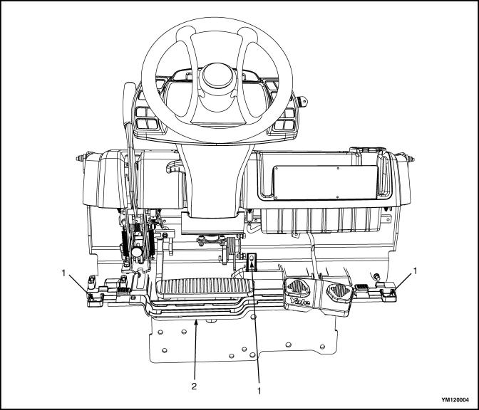
5.Remove floor mat and floor plate. See Figure 4.
6.Remove two capscrews holding left and right rear side covers to the frame. Remove rear side covers from frame. See Figure 4.
7.Remove two capscrews holding left and right fender covers to front overhead guard leg. Remove covers. See Figure 4.
8.Remove four capscrews holding left and right front side covers to frame. Remove covers.
9.Fully lower the steering column.
10.Remove upper steering column cover by pulling up on upper steering column cover to release latches (one on either side), and pulling cover away from steering column. See Figure 5.
11.Remove five fasteners (see Figure 5) securing dash to the top of cowl. Remove four clips, located underneath dash, that attach dash to the kick panel. Lift to remove dash.
12.Lift kick panel to remove it from truck. See Figure 4.
13.Remove three capscrews holding the seal plate. Remove seal plate. See Figure 6.
14.Disconnect seat wire harness connector. See Figure 3.
CAUTION
When removing the seat from the hood, DO NOT use an impact wrench to remove the capscrews. Damage can be caused to the threads on the screws and in the holes.
15.If seat is to be removed, and truck is equipped with a non-swivel seat, remove seat wire harness from seat wire harness brackets that are attached to the underside of hood. Remove the cable clips from the seat wire harness. If truck is equipped with a swivel seat, remove seat wire harness from seat wire harness bracket attached to underside of hood and behind the seat. See Figure 3.
16.Remove four capscrews and washers holding seat to the hood. Lift seat off the hood. Pull seat wire harness through hood. See Figure 3.
17.Remove capscrews and washers at top of the gas springs. Remove gas springs from hood.
18.Remove hinge screws, located in the rear of the hood.
19.Lift hood from the truck. See Figure 3.
INSTALL
1.Place hood onto the lift truck frame.
2.Install hinge screws, located in the rear of the hood, and tighten to 38 N•m (28 lbf ft). See Figure 3.
3.Align top holes in the gas springs with holes in hood. There are two sets of holes used to install the gas springs to hood, based on the type of seat installed on lift truck. One set is for installing the cylinder end of the gas springs and the other set is for attaching the rod end of the gas springs. Install capscrews and washers to attach gas springs to the hood. Refer to Figure 7 and Table 1 for correct holes used to connect the rod end of the cylinder, depending on the type of seat instal-
led on the lift truck. Tighten capscrews to 19.2 N•m (170 lbf in).
4
0100 YRM 1243 |
Hood, Seat, and Side Covers Replacement |
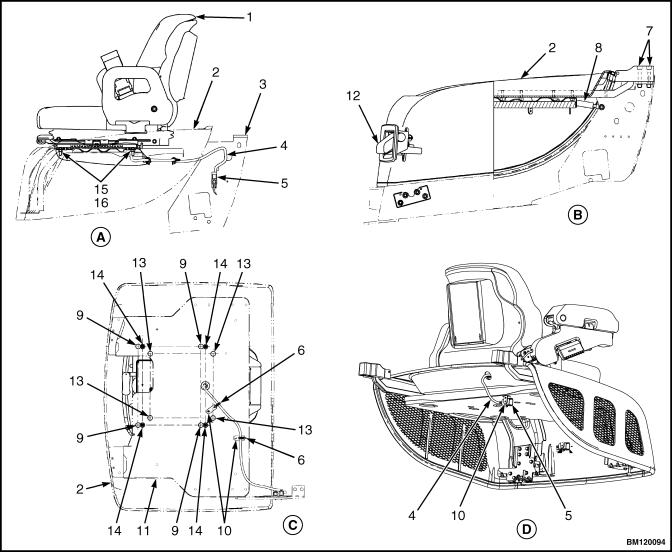
NOTE: SWIVEL SEAT AND VENTED HOOD ARE OPTIONAL FEATURES.
A.SIDE VIEW OF HOOD AND SEAT
B.SIDE VIEW OF HOOD
1.SEAT
2.HOOD
3.FRAME
4.SEAT WIRE HARNESS
5.SEAT WIRE HARNESS CONNECTOR
6.CABLE CLIPS
7.HINGE SCREWS
8.GAS SPRING
9.ATTACHMENT HOLES ATTACHING HOOD TO SEAT (SEMI-SUSPENSION)
C.BOTTOM VIEW OF HOOD
D.SIDE VIEW OF VENTED HOOD WITH SWIVEL SEAT
10.SEAT WIRE HARNESS BRACKETS
11.SEAT LINER
12.HOOD LATCH
13.ATTACHMENT HOLES ATTACHING HOOD TO SEAT (NON-SUSPENSION)
14.ATTACHMENT HOLES ATTACHING HOOD TO SEAT (FULL SUSPENSION)
15.SPACER
16.FLANGE NUT
Figure 3. Hood and Seat Arrangement
5
Hood, Seat, and Side Covers Replacement |
0100 YRM 1243 |
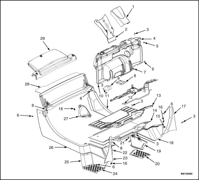
1. |
UPPER STEERING COLUMN COVER |
19. |
LEFT PANEL |
2. |
LOWER STEERING COLUMN COVER |
20. |
LEFT STEP PLATE |
3. |
CAPSCREW |
21. |
LOCK NUT |
4. |
DASH ASSEMBLY |
22. |
RIGHT FRONT SIDE COVER |
5. |
INSERT |
23. |
RIGHT FENDER COVER |
6. |
SCREW |
24. |
RIGHT STEP PLATE |
7. |
CLIP |
25. |
RIGHT PANEL |
8. |
SEAL |
26. |
RIGHT REAR SIDE COVER |
9. |
GROMMET |
27. |
SPLASH SHIELD |
10. |
KICK PANEL |
28. |
RADIATOR COVER GLC40, 45, 55VX; |
11. |
LEFT REAR SIDE COVER |
|
GLC55SVX; (GC/GLC080, 100, 120VX; GC/ |
12. |
SEAL PLATE ASSEMBLY |
|
GLC080, 100VXBCS; GC/GLC120SVX; GC/ |
13. |
FLOOR MAT |
29. |
GLC120VXPRS) (E818, F818) |
14. |
FLOOR PLATE |
RADIATOR COVER (GLP/GDP40VX5/VX6; GLP/ |
|
15. |
CLIP NUT |
|
GDP45SVX5, GLP/GDP45VX6; GLP/ |
16. |
FOLDOVER NUT |
|
GDP50-55VX (GP/GLP/GDP080, 090, 100, 110, |
17. |
LEFT FENDER COVER |
|
120VX) (F813, G813, H813, J813) |
18. |
LEFT FRONT SIDE COVER |
|
|
Figure 4. Side Covers, Floor Plate, and Cowl Components
6
0100 YRM 1243 |
Hood, Seat, and Side Covers Replacement |
NOTE: TOP VIEW OF DASH SHOWN. |
|
|
|
A. |
INDICATES TO PULL UP TO UNLATCH |
|
|
1. |
ALLEN SCREWS |
3. |
UPPER STEERING COLUMN COVER |
2. |
COWL |
4. |
LOWER STEERING COLUMN COVER |
Figure 5. Remove Dash From Cowl
7
Hood, Seat, and Side Covers Replacement |
0100 YRM 1243 |
1. CAPSCREWS |
2. SEAL PLATE |
Figure 6. Remove Seal Plate From Dash
8

0100 YRM 1243 |
Hood, Seat, and Side Covers Replacement |
Figure 7. Gas Spring Installation
9
Hood, Seat, and Side Covers Replacement |
0100 YRM 1243 |
|
Legend for Figure 7 |
||
NOTE: SEE TABLE 1 FOR HOLES TO USE TO ATTACH ROD END OF GAS SPRING. |
|||
A. |
GLC40, 45, 55VX; GLC55SVX; (GC/GLC080, |
C. |
LEFT SIDE |
|
100, 120VX; GC/GLC080, 100VXBCS; GC/ |
D. |
RIGHT SIDE |
B. |
GLC120SVX; GC/GLC120VXPRS) (E818, F818) |
|
|
GLP/GDP40VX5/VX6; GLP/GDP45SVX5, GLP/ |
|
|
|
|
GDP45VX6; GLP/GDP50-55VX (GP/GLP/ |
|
|
|
GDP080, 090, 100, 110, 120VX) (F813, G813, |
|
|
|
H813, J813) |
|
|
1.MOUNTING LOCATION FOR CYLINDER END OF GAS SPRING FOR NON-SUSPENSION SEAT
2.MOUNTING LOCATION FOR CYLINDER END OF GAS SPRING FOR SEMI OR FULL SUSPENSION SEAT
Table 1. Gas Spring Installation, Holes for Installing Rod Ends (See Figure 7)
Counterweight |
Full or Semi Suspension Seat |
Non-Suspension Seat |
|||
Type |
|
|
|
|
|
Left Side |
Right Side |
Left Side |
Right Side |
||
|
|||||
|
|
|
|
|
|
Standard |
|
|
|
|
|
Counterweight |
|
|
|
|
|
GLC40, 45, 50, 55VX |
3 |
3 |
1 |
1 |
|
(GC/GLC080, 100, |
|
|
|
|
|
120VX) (E818, F818) |
|
|
|
|
|
|
|
|
|
|
|
Standard |
|
|
|
|
|
Counterweight GLP/ |
|
|
|
|
|
GDP40VX5/VX6; |
|
|
|
|
|
GLP/GDP45SVX5, |
|
|
|
|
|
GLP/GDP45VX6; |
2 |
2 |
1 |
1 |
|
GLP/GDP50-55VX |
|||||
|
|
|
|
||
(GP/GLP/GDP080, |
|
|
|
|
|
090, 100, 110, |
|
|
|
|
|
120VX) (F813, G813, |
|
|
|
|
|
H813, J813) |
|
|
|
|
|
BCS and PRS |
|
|
|
|
|
Counterweights |
|
|
|
|
|
GLC55SVX (GC/ |
|
|
|
|
|
GLC080, |
2 |
4 |
2 |
4 |
|
100VXBCS, GC/ |
|||||
|
|
|
|
||
GLC120SVX; GC/ |
|
|
|
|
|
GLC120VXPRS) |
|
|
|
|
|
(E818, F818) |
|
|
|
|
|
|
|
|
|
|
|
10
0100 YRM 1243
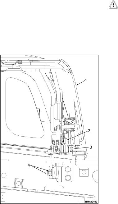
4.Install latch striker in highest slot position. Check that latch striker is in center of jaws of hood latch when hood closes. Open and close hood to ensure that center pin strikes hood latch properly and that the stop screw contacts the frame. A properly closed hood MUST click twice on the hood latch. If the hood latch does not close properly, loosen capscrews on the back of center pin and adjust center pin up or down as required for correct alignment. See Figure 8.
5.Push down until hood just touches rubber bumper. Make sure latch striker is still in center of hood latch. Open hood and tighten capscrews for latch.
1. |
HOOD |
3. |
CENTER PIN |
2. |
HOOD LATCH |
4. |
CAPSCREW |
Figure 8. Hood Latch Adjustment
Steering Column
6.Check operation of hood latch. Have an operator sit in seat. Make sure hood is fully closed (two clicks). Also check that hood touches rubber bumper. If necessary, repeat Step 5.
CAUTION
When installing the seat to the hood, DO NOT use an impact wrench to install the capscrews. Damage can be caused to the threads on the screws and in the holes.
7.Place seat on the hood and thread seat wire harness through the hole in the hood. See Figure 3.
8.Align holes in the seat with the holes in hood. Insert washers and capscrews. Tighten capscrews to 18 N•m (159 lbf in).
9.If truck is equipped with a non-swivel seat, tie cable clips to seat wire harness and insert harness into seat wire harness brackets under hood. If truck is equipped with a swivel seat, secure seat harness to bracket. See Figure 3.
10.Install seal plate using three capscrews. See Figure 6.
11.Install kick panel onto truck. See Figure 4.
12.Install dash to top of cowl. See Figure 5. Install four clips to attach dash to kick panel.
13.Install upper steering column cover to dash.
14.Using four capscrews, install left and right front side covers to frame. See Figure 4.
15.Using two capscrews, install left and right fender covers to front of overhead guard legs.
16.Using two capscrews, install left and right rear side covers to frame. See Figure 4.
17.Install floor mat and floor plate.
18.If truck is equipped with an LPG tank, swing LPG tank into position on back of counterweight.
19.Adjust the steering column and seat positions.
11
Steering Column |
0100 YRM 1243 |
Steering Column
DESCRIPTION
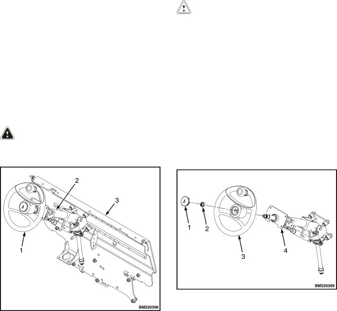
This section describes the repair procedures for the steering column. The steering column assembly mounts to the cowl inside the operator compartment and is the mechanical connection between the steering wheel and the steering control unit. The steering column includes the steering wheel, housing, bracket and lower shaft. For lift trucks with gas and LPG engines, bolts and bushings attach the steering column to the cowl standoffs. For lift trucks with diesel engines, bolts, bushings and isolators attach the steering column to the cowl standoffs. See Figure 9.
STEERING COLUMN REPAIR
Remove
1.Put blocks on each side (front and back) of tires to prevent lift truck from moving.
WARNING
Disconnect the battery before removing any covers to avoid injury to personnel.
2.Attach a tag on battery connector or negative battery cable stating, DO NOT CONNECT BATTERY. Move steering column to most FORWARD position.
CAUTION
If a puller tool is used to remove steering wheel from steering column, be careful not to damage horn wires.
NOTE: This procedure is for removal of all components of steering column assembly. Not all components are removed for a repair procedure. Do only those steps of procedure necessary to remove required component.
NOTE: Tag wires prior to disconnect.
3.Remove horn button assembly and disconnect electrical wires. Remove large hex nut and steering wheel from steering column. See Figure 10.
4.Remove steering column covers. Remove floor mats and floor plate. See section Hood, Seat, and Side Covers Replacement.
|
1. |
HORN BUTTON |
|
2. |
HEX NUT |
NOTE: DIESEL SHOWN, LPG AND GAS SIMILAR. |
3. |
STEERING WHEEL |
4. |
STEERING COLUMN |
1. |
STEERING WHEEL |
Figure 10. Steering Wheel Remove/Install |
2. |
STEERING COLUMN |
|
3. |
COWL |
|
Figure 9. Steering Column and Cowl
12
0100 YRM 1243
NOTE: Perform Step 5 for lift trucks equipped with gas or LPG engines.
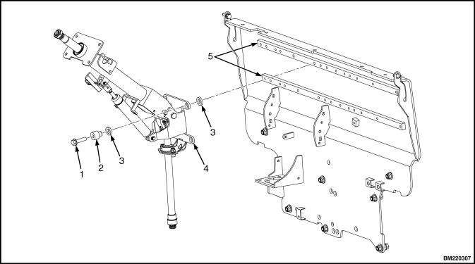
5.Remove four capscrews, four bushings and steering column from cowl standoffs. See Figure 11.
NOTE: Perform Step 6 for lift trucks equipped with diesel engines.
6.Remove four capscrews, four bushings, four isolators, steering column and four isolators from cowl standoffs. See Figure 11.
Disassemble
1. Remove two pins and gas spring from housing.
See Figure 12, for lift trucks manufactured before January, 2012.
See Figure 13, for lift trucks manufactured after January, 2012.
2.Remove two pivot bolts, two bushings, two nuts and bracket from housing.
Steering Column
See Figure 12, for lift trucks manufactured before January, 2012.
See Figure 13, for lift trucks manufactured after January, 2012.
3.Remove split pin and lower shaft from upper shaft.
See Figure 12, for lift trucks manufactured before January, 2012.
See Figure 13, for lift trucks manufactured after January, 2012.
4.Remove connector from connector bracket. Remove connector bracket, fastener, four screws and two horn contacts from housing.
See Figure 12, for lift trucks manufactured before January, 2012.
See Figure 13, for lift trucks manufactured after January, 2012.
1. |
CAPSCREW |
4. |
STEERING COLUMN |
2. |
BUSHING |
5. |
COWL STANDOFF |
3. |
ISOLATOR |
|
|
Figure 11. Steering Column Remove/Install
13

Steering Column |
0100 YRM 1243 |
Figure 12. Steering Column Assembly, Lift Trucks Manufactured Before January, 2012
14
 Loading...