


ERP15-20VT (G807)
SERVICE MANUAL CONTENTS
SECTION |
PART |
YRM |
REV |
NUMBER |
NUMBER |
DATE |
|
FRAME............................................................................................................................ |
524295629 |
0100 YRM 1329 |
09/14 |
OPERATOR'S CAB........................................................................................................ |
550025937 |
0100 YRM 1446 |
09/14 |
AC MOTOR REPAIR...................................................................................................... |
524327049 |
0620 YRM 1385 |
09/14 |
TRANSAXLE................................................................................................................... |
524295630 |
1300 YRM 1330 |
09/12 |
STEERING SYSTEM...................................................................................................... |
524295631 |
1600 YRM 1331 |
09/14 |
BRAKE SYSTEM............................................................................................................ |
524295632 |
1800 YRM 1332 |
12/10 |
HYDRAULIC SYSTEM.................................................................................................... |
524295633 |
1900 YRM 1333 |
09/14 |
HYDRAULIC CLEANLINESS PROCEDURES............................................................... |
550073240 |
1900 YRM 1620 |
12/14 |
MAIN CONTROL VALVES............................................................................................. |
524319495 |
2000 YRM 1334 |
09/14 |
CYLINDER REPAIR (MAST S/N A270-72, A551, A555, A559, A626, A627, A751-52, |
|
|
|
B551, B555, B586-91, B749-54, C661-63, C665, D507-09, D515, D562-64, E509, |
524319496 |
2100 YRM 1382 |
03/14 |
E564).......................................................................................................................... |
|||
WIRE HARNESS REPAIR.............................................................................................. |
524223769 |
2200 YRM 1128 |
12/14 |
USER INTERFACE SUPERVISOR................................................................................. |
524319497 |
2200 YRM 1335 |
09/14 |
USER INTERFACE SERVICE TECHNICIAN................................................................. |
524319498 |
2200 YRM 1336 |
09/14 |
ELECTRICAL SYSTEM.................................................................................................. |
524320282 |
2200 YRM 1337 |
09/14 |
INDUSTRIAL BATTERY................................................................................................. |
524158040 |
2240 YRM 0001 |
09/14 |
MAST REPAIR (S/N A270, A271, A272)........................................................................ |
524327054 |
4000 YRM 1386 |
02/14 |
MAST REPAIR (S/N C661, C662, C663, C665)............................................................. |
524333799 |
4000 YRM 1405 |
05/14 |
METRIC AND INCH (SAE) FASTENERS....................................................................... |
524150797 |
8000 YRM 0231 |
10/13 |
PERIODIC MAINTENANCE............................................................................................ |
524320290 |
8000 YRM 1339 |
09/14 |
CAPACITIES AND SPECIFICATIONS........................................................................... |
524306565 |
8000 YRM 1340 |
09/14 |
DIAGRAMS..................................................................................................................... |
524319503 |
8000 YRM 1341 |
09/14 |
DIAGNOSTIC TROUBLESHOOTING MANUAL............................................................ |
524319504 |
9000 YRM 1377 |
10/14 |
Service information for Cummins diesel engines can be ordered through the Hyster Literature Distribution Center.
PART NO. 524320408 (12/14)

SAFETY PRECAUTIONS
MAINTENANCE AND REPAIR
•When lifting parts or assemblies, make sure all slings, chains, or cables are correctly fastened, and that the load being lifted is balanced. Make sure the crane, cables, and chains have the capacity to support the weight of the load.
•Do not lift heavy parts by hand, use a lifting mechanism.
•Wear safety glasses.
•DISCONNECT THE BATTERY CONNECTOR before doing any maintenance or repair on electric lift trucks. Disconnect the battery ground cable on internal combustion lift trucks.
•Always use correct blocks to prevent the unit from rolling or falling. See HOW TO PUT THE LIFT TRUCK ON BLOCKS in the Operating Manual or the Periodic Maintenance section.
•Keep the unit clean and the working area clean and orderly.
•Use the correct tools for the job.
•Keep the tools clean and in good condition.
•Always use YALE APPROVED parts when making repairs. Replacement parts must meet or exceed the specifications of the original equipment manufacturer.
•Make sure all nuts, bolts, snap rings, and other fastening devices are removed before using force to remove parts.
•Always fasten a DO NOT OPERATE tag to the controls of the unit when making repairs, or if the unit needs repairs.
•Be sure to follow the WARNING and CAUTION notes in the instructions.
•Gasoline, Liquid Petroleum Gas (LPG), Compressed Natural Gas (CNG), and Diesel fuel are flammable. Be sure to follow the necessary safety precautions when handling these fuels and when working on these fuel systems.
•Batteries generate flammable gas when they are being charged. Keep fire and sparks away from the area. Make sure the area is well ventilated.
NOTE: The following symbols and words indicate safety information in this manual:
 WARNING
Indicates a hazardous situation which, if not avoided, could result in death or serious injury.
CAUTION
Indicates a hazardous situation which, if not avoided, could result in minor or moderate injury and property damage.
On the lift truck, the WARNING symbol and word are on orange background. The CAUTION symbol and word are on yellow background.
Transaxle |
Table of Contents |
TABLE OF CONTENTS |
|
General................................................................................................................................................................ |
1 |
Discharging the Capacitors ............................................................................................................................. |
2 |
Special Tools ................................................................................................................................................... |
2 |
Transaxle Assembly............................................................................................................................................. |
3 |
Remove Transaxle From Frame ...................................................................................................................... |
3 |
Remove the Parking Brake and Traction Motor............................................................................................... |
4 |
Install Parking Brake and Traction Motor......................................................................................................... |
4 |
Install Transaxle to Frame ............................................................................................................................... |
5 |
Maintenance and Repair ..................................................................................................................................... |
6 |
Speed Sensor Repair...................................................................................................................................... |
6 |
Trunnion Cap Repair ....................................................................................................................................... |
6 |
Fluid Level Check............................................................................................................................................ |
8 |
Fluid Change................................................................................................................................................... |
8 |
Breather Repair............................................................................................................................................... |
9 |
Stud Repair ..................................................................................................................................................... |
10 |
Brake Cylinder Repair ..................................................................................................................................... |
11 |
Input Seal Repair ............................................................................................................................................ |
13 |
Cover to Housing Seal .................................................................................................................................... |
13 |
During the Transaxle Warranty Period ........................................................................................................ |
13 |
After the Transaxle Warranty Period ........................................................................................................... |
14 |
Removing the Cover ............................................................................................................................... |
14 |
Installing the Cover ................................................................................................................................. |
15 |
Wet Brakes...................................................................................................................................................... |
16 |
This section is for the following models: |
|
ERP15-20VT (ERP030-040VT) [G807]; |
|
ERP16-20VF (ERP30-40VF) [A955] |
|
©2012 Yale Materials Handling Corp. |
i |
1300 YRM 1330 |
General |
General
 CAUTION
DO NOT remove the cover from the transaxle housing during the warranty period. Removing the cover from the housing will void the transaxle warranty. The transaxle warranty period may vary from truck hours or other warranties. Contact Yale Company Contact Management if you have questions about warranty status.
 CAUTION
Use only transmission fluid from approved vendors. Using fluid from unapproved vendors will void the warranty. Contact Yale Company Contact Management if you have questions about warranty status.
This section contains the removal, repair, inspection, and installation instructions for the transaxle assemblies used on these models.
 WARNING
DO NOT make repairs or adjustments unless you have been properly trained and authorized to do so. Improper repairs and adjustments can create dangerous operating conditions. DO NOT operate a lift truck that needs repairs. Report the need for repairs to your supervisor immediately. If repair is necessary, attach a DO NOT OPERATE tag on the steering wheel and disconnect the battery.
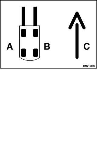
Throughout this section, forward will refer to travel in the direction of the forks and left and right will be determined by sitting in the seat facing forward. See Figure 1 or Figure 2.
|
|
|
A. |
LEFT SIDE |
C. FORWARD |
B. |
RIGHT SIDE |
TRAVEL |
Figure 1. Truck Orientation (Three-Wheel Trucks)
|
|
|
A. |
LEFT SIDE |
C. FORWARD |
B. |
RIGHT SIDE |
TRAVEL |
Figure 2. Truck Orientation (Four-Wheel Trucks)
1
General
DISCHARGING THE CAPACITORS
 WARNING
DO NOT make repairs or adjustments unless you have been properly trained and authorized to do so. Improper repairs and adjustments can create dangerous operating conditions. DO NOT operate a lift truck that needs repairs. Report the need for repairs to your supervisor immediately. If repair is necessary, attach a DO NOT OPERATE tag on the steering wheel and disconnect the battery.
Disconnect the battery and allow the capacitors to discharge before opening any compartment covers or inspecting or repairing the electrical system. DO NOT place tools on top of the battery. If a tool causes a short circuit, the high current flow from the battery can cause personal injury or property damage.
Some checks and adjustments are performed with the battery connected. DO NOT connect the battery until the procedure instructs you to do so. Never wear any metallic items on your fingers, arms, or neck. Metal items can accidentally make an electrical connection and cause injury.
Before performing any tests or adjustments, block the lift truck to prevent unexpected movement.
The capacitor in the transistor controller(s) can hold an electrical charge for about 10 seconds after the battery is disconnected. To prevent an electrical shock and personal injury, discharge the capacitor(s) before inspecting or repairing any component in the drive unit compartment. Make certain that the battery has been disconnected.
DO NOT short across the motor controller terminals with a screwdriver or jumper wire.
Make certain the Emergency Disconnect Switch has not been activated. This will isolate the controller and prevent the capacitors from discharging properly. The proper way to disconnect the battery is by separating the battery connectors.
1.Ensure capacitors are discharged by performing Step 2 through Step 6 below.
2.Turn key or keyless switch to OFF position.
3.Disconnect battery by separating connectors.
1300 YRM 1330
4.Block drive wheels to prevent lift truck from moving.
5.Make sure Emergency Disconnect Switch HAS NOT been activated. If Emergency Disconnect Switch is activated, rotate switch to the right until it pops up.
6.Press horn button. Wait 30 seconds to be sure capacitors are fully discharged.
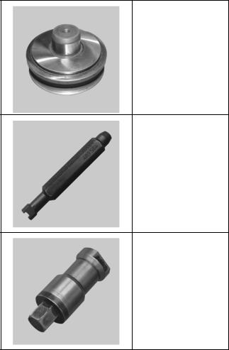
SPECIAL TOOLS
Special tools are necessary to properly perform some repairs. These tools are available from your Yale dealer. Warranty will not cover damage resulting from work done using improper tools. Refer to Table 1.
Table 1. Yale Special Tools
Input Seal Driver
Yale Part No.
582000161
Breather Set Tool
Yale Part No.
582000187
Wheel Stud Tool
Yale Part No.
582000162
2
1300 YRM 1330 |
Transaxle Assembly |
Transaxle Assembly
REMOVE TRANSAXLE FROM FRAME
 WARNING
The lift truck must be put on blocks for some types of maintenance and transaxle repair. The removal of the battery, mast, transaxle, or the counterweight will cause large changes in the center of gravity. Position additional blocks under the frame when the lift truck is on blocks, so the lift truck cannot tip over.
1.Remove mast assembly.
See Mast Repair, 2- and 3-Stage High Visibility Masts 4000 YRM 1386 for European lift truck models
•ERP15-20VT (G807)
•ERP16-20VF (A955)
See Mast Repair, 2-, 3-, And 4-Stage Heavy Duty Masts 4000 YRM 1405 for European and American lift truck models
•ERP15-20VT (ERP030-040VT) (G807)
•ERP16-20VF (ERP30-40VF) (A955)
2.Turn key switch to OFF position and disconnect battery.
3.Position lift truck frame on blocks so drive tires are suspended off the floor.
See Periodic Maintenance 8000 YRM 1339 for lift truck models
•ERP15-20VT (ERP030-040VT) (G807)
See Periodic Maintenance 8000 YRM 1373 for lift truck models
• ERP16-20VF (ERP30-40VF) (A955)
4.Remove drive tire lug nuts and drive tire and wheel assembly.
5.Disconnect transaxle speed sensor connector from main wiring harness.
6.Disconnect parking brake connector from main wiring harness.
7.Disconnect manual override cable from parking brakes.
8.Tag and disconnect power cables from traction motor studs.
9.Disconnect traction motor temperature sensor at traction motor.
10.Disconnect service brake line from port on transaxle. Cap brake line and plug port on transaxle to reduce the possibility of contamination entering brake system.
11.Loosen, but do not remove, five mounting capscrews and nuts that hold transaxle assembly on lift truck.
 WARNING
The transaxle and traction motor assemblies are heavy. Be sure that all lifting devices are suitable and of adequate capacity to lift the transaxle and traction motor.
12.Position a floor jack under transaxle assembly. Make sure assembly is properly balanced on floor jack so it will not fall once mounting capscrews have been removed.
 CAUTION
Check that cables, hoses, and wires do not interfere with the removal of the transaxle assembly.
13.Remove five capscrews and washers holding transaxle on lift truck frame. Carefully lower transaxle assembly from lift truck frame using floor jack.
 WARNING
The transaxle and traction motor assemblies are heavy. Be sure that all lifting devices are suitable and of adequate capacity to lift the transaxle and traction motor.
14.Transfer transaxle assembly from floor jack to a clean workbench using an appropriate sling and overhead lifting device.
3

Transaxle Assembly
REMOVE THE PARKING BRAKE AND TRACTION MOTOR
 WARNING
Cleaning solvents can be flammable and toxic and can cause skin irritation. When using cleaning solvents, always follow the solvent manufacturer’s recommended safety procedures.
 WARNING
The traction motor is heavy. Be sure that all lifting devices are suitable and of adequate capacity to lift the traction motor.
1.Position transaxle on blocks with studs down. Securely support in this position.
2.Remove parking brake assembly from traction motor:
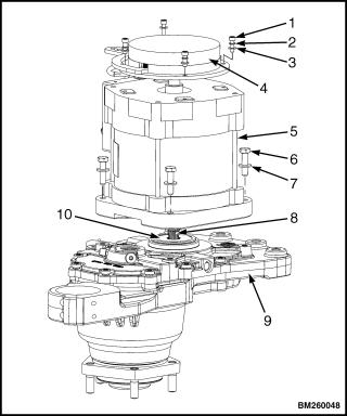
a.Remove four capscrews, lockwashers, and washers holding brake assembly on traction motor. See Figure 3.
b.Pry evenly on opposite sides to remove brake assembly from brake hub. Remove brake assembly by hand.
c.Remove snap ring holding brake hub on traction motor shaft. Slide hub from shaft. Remove snap ring and woodruff key from beneath hub.
3.Remove traction motor from transaxle:
a.Install an eyebolt to traction motor shaft and attach an overhead lifting device of adequate capacity to eyebolt.
b.Remove four capscrews and washers mounting traction motor to transaxle.
c.Lift traction motor from transaxle using overhead lifting device.
INSTALL PARKING BRAKE AND TRACTION MOTOR
 WARNING
Cleaning solvents can be flammable and toxic and can cause skin irritation. When using cleaning solvents, always follow the solvent manufacturer’s recommended safety procedures.
1300 YRM 1330
 WARNING
The traction motor is heavy. Be sure that all lifting devices are suitable and of adequate capacity to lift the traction motor.
1.Position transaxle on blocks with studs down. Securely support in this position.
2.Install traction motor on transaxle:
a.Install an eyebolt to traction motor shaft and attach an overhead lifting device of adequate capacity to eyebolt.
b.Lightly lubricate inside lip of transaxle input shaft with multipurpose grease to ensure seal seats properly on traction motor shaft. It is not necessary to lubricate traction motor shaft as it is lubricated internally within the transaxle. See Figure 4.
|
|
|
|
1. |
CAPSCREW |
6. |
CAPSCREW |
2. |
LOCKWASHER |
7. |
WASHER |
3. |
WASHER |
8. |
MOTOR SHAFT |
4. |
PARKING BRAKE |
9. |
TRANSAXLE |
|
ASSEMBLY |
10. |
INPUT SEAL |
5.TRACTION MOTOR
Figure 3. Traction Motor and Parking Brake
4
1300 YRM 1330 |
Transaxle Assembly |
c.Lift traction motor and position it on transaxle using overhead lifting device. Guide traction motor shaft into transaxle through input seal. Align motor with transaxle.
d.Install four capscrews and washers mounting traction motor on transaxle. Tighten capscrews to 48 N•m (35 lbf in).
e.Remove eyebolt from traction motor shaft.
3.Install parking brake assembly to traction motor:
a.Install lower snap ring and woodruff key on traction motor shaft. Align groove in hub with woodruff key and slide hub onto shaft. Install upper snap ring holding brake hub onto traction motor shaft.
b.Position brake assembly onto brake hub. Align splines and seat brake on traction motor end head.
|
|
|
|
1. |
CAPSCREW |
6. |
CAPSCREW |
2. |
LOCKWASHER |
7. |
WASHER |
3. |
WASHER |
8. |
MOTOR SHAFT |
4. |
PARKING BRAKE |
9. |
TRANSAXLE |
|
ASSEMBLY |
10. |
INPUT SEAL |
5.TRACTION MOTOR
Figure 4. Traction Motor and Parking Brake
c.Install four capscrews, lockwashers, and washers to secure brake assembly. Tighten capscrews to 8 N•m (71 lbf in).
INSTALL TRANSAXLE TO FRAME
1.Check that dowels are installed in transaxle housing and are in good condition. Replace as necessary.
 WARNING
The transaxle and traction motor assembly are heavy. Be sure that all lifting devices are suitable and of adequate capacity to lift the transaxle and traction motor.
2.Move transaxle assembly onto a floor jack using an appropriate sling and lifting device. Make sure assembly is balanced and properly supported so it will not fall during installation.
3.Carefully position transaxle on frame using floor jack. Align transaxle mounting dowels with their mounting holes in frame.
4.Apply Loctite® 271 to five socket head capscrews and washers. Install capscrews with washers through transaxle and into mounting holes in frame. Tighten capscrews to 220 N•m (162 lbf ft).
5.Remove cap and plug from service brake line and service brake port. Install service brake line to service brake port. Tighten to 12 to 16 N•m (108 to 192 lbf in).
6.Connect power cables to traction motor studs as tagged during removal. Tighten to 8 N•m (71 lbf in).
7.Connect traction motor temperature sensor connectors to main wiring harness.
8.Connect parking brake connector to main wiring harness.
9.Connect manual override cable to parking brakes.
10.Connect transaxle speed sensor connector to main wiring harness.
5
Maintenance and Repair
 CAUTION
Make sure the lift truck is blocked at the same height as with the drive tire installed to ensure the proper fluid level reading.
11.Bleed the service brakes. Refer Brake System 1800 YRM 1332 for procedures.
12.Check fluid level in transaxle. Fill as necessary. See Fluid Level Check.
13.Install drive tire and wheel assembly on wheel hub. Install lug nuts and tighten to 170 N•m (125 lbf ft).
14.Connect battery connector, turn key switch to ON position, and test lift truck for proper operation.
15.Lower lift truck from the blocks.
See Periodic Maintenance 8000 YRM 1339 for lift truck models
• ERP15-20VT (ERP030-040VT) (G807)
1300 YRM 1330
See Periodic Maintenance 8000 YRM 1373 for lift truck models
•ERP16-20VF (ERP30-40VF) (A955)
16.Install mast on lift truck.
See Mast Repair, 2- and 3-Stage High Visibility Masts 4000 YRM 1386 for European lift truck models
•ERP15-20VT (G807)
•ERP16-20VF (A955)
See Mast Repair, 2-, 3-, And 4-Stage Heavy Duty Masts 4000 YRM 1405 for European and American lift truck models
•ERP15-20VT (ERP030-040VT) (G807)
•ERP16-20VF (ERP30-40VF) (A955)
Maintenance and Repair
SPEED SENSOR REPAIR
The speed sensor monitors the speed of the transaxle and relays the information to the controller. The speed sensor can be replaced with the transaxle installed to the lift truck.
1.Park lift truck on a level surface. Turn key switch to OFF position and unplug battery connector.
2.Discharge capacitors. See section Discharging the Capacitors.
3.Remove floor mat and floor plates from operator compartment to access top of transaxle(s).
4.Disconnect sensor wiring harness from main wiring harness.
 CAUTION
Use a brush to clean around the sensor before removing to avoid contaminating the transaxle.
5.Remove capscrew holding sensor to transaxle using a 5mm Allen wrench. See Figure 5.
6.Pull sensor out of transaxle.
7.Insert new sensor into transaxle.
8.Align screw holes and install capscrew. Tighten capscrew to 9.5 N•m (84.0 lbf in).
9.Connect sensor wiring harness to main wiring harness.
10.Replace floor plates and floor mat in operator compartment.
11.Connect battery, turn key to ON position and test lift truck for proper operation.
TRUNNION CAP REPAIR
To repair the trunnion cap:
1.Remove load from forks and park lift truck on a level surface. Adjust mast to a vertical position, then turn key switch to OFF position and separate battery connectors.
2.Remove four capscrews holding trunnion cap on transaxle housing. Remove trunnion cap. See Figure 6.
3.Wipe away any dirt or grease near mounting holes. Clean holes with a proper sized tap and tap wrench as necessary.
6

1300 YRM 1330 |
Maintenance and Repair |
4.Position new cap over mast pin and onto transaxle.
5.Apply Loctite® 242 to threads and install four capscrews and tighten alternately in small increments. Tighten capscrews to 24 N•m (216 lbf in).
6.Grease fitting in mast stub shaft to lubricate trunnion cap.
7.Connect battery, turn key to ON position and test lift truck for proper operation.
1. CAPSCREWS
2. TRUNNION CAP
3. THREADED MOUNTING HOLES
4. TRANSAXLE HOUSING
Figure 6. Trunnion Cap
1.CAPSCREW
2.SPEED SENSOR
3.FILL PLUG
4.TRANSAXLE COVER
5.COVER CAPSCREWS
6.DRAIN PLUG
Figure 5. Speed Sensor
7
 Loading...