

Yaesu VXA-100 Operating Manual

VXA-100
Operating Manual

Congratulations!
You now have at your fingertips a valuable communications tool-a YAESU two-
way radio ! Rugged, reliable and easy to use, your YAESU radio will keep you in
constant touch with your colleagues for years to come, with negligible maintenance down-time.
Please take a few minutes to read this manual carefully. The information presented here will allow you to derive maximum performance from your radio, in
case questions arise later on.
We're glad you joined the YAESU team. Call on us anytime, because commu-
nications is our business. Let us help you get your message across.
NOTICE
There are no user-serviceable points inside this
transceiver. All service jobs must be referred
to your Authorized Service Center.

INTRODUCTION
The Yaesu VXA-100
bility on the international Aircraft Communication Band (118 ~ 136.975 MHz); offers transmit and receive
capability on the aircraft “COM” band, additionally provides VOR and CDI navigation features on the “NAV”
band (108 ~ 117.975 MHz).
The VXA-100 includes our exclusive Omni-Glow™ display back-lighting, for minimal degradation of your
night vision, NOAA weather band monitoring capability, 8 character Alpha/Numeric Display, 50 Memory
Channels and 250 Book Memory Channels.
W e recommend that you read this manual in its entirety, so as to understand the many features of the VXA-100
completely. Keep this manual handy, so you may use it for reference.
Aviator Pilot
is compact, rugged hand-held transceiver providing communication capa-
Note: The VXA-100’s VOR and CDI Navigation features
are supplemental aids to navigation only, and are not intended to be a substitute for accurate (primary) VOR/CDI
or landing service equipment.
VXA-100 AVIATOR PILOT OPERATING MANUAL
1
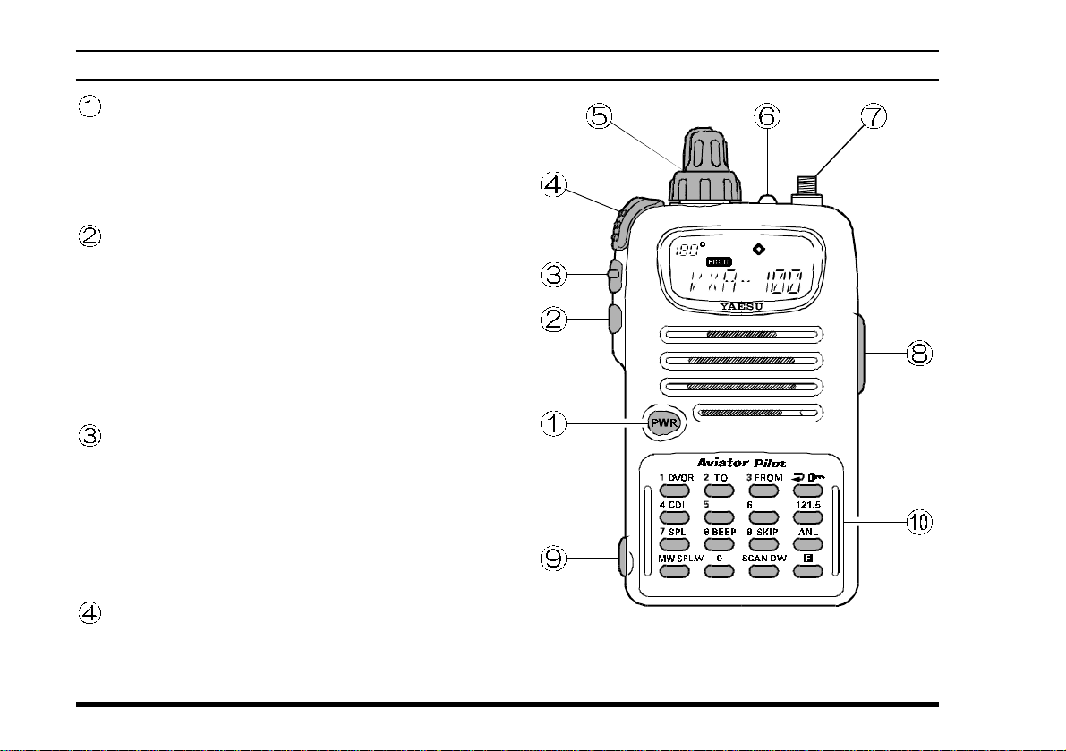
CONTROLS & CONNECTORS
PWR Switch
This is the main On/Off switch for the transceiver.
Press and hold in this switch for ½ second to turn
the radio on. When the radio is on, press and hold
in this switch for 2 seconds to turn the radio off.
LAMP Switch
Press this switch momentarily, to activate the
back-lighting lamp for the display and keypad
keys. Press and hold this switch for 2 seconds, to
activate the back-lighting lamp continuously. To
turn the lamp off, press this switch again. The
LAMP switch may be configured in several ways
via the Menu; see page 34 for details.
MONITOR Switch
This button may be pressed to “open” the squelch
manually, allowing you to listen for very weak
signals. Press and hold this button for 2 seconds,
to “open” the squelch continuously. Press this
button again to resume normal (quiet) monitoring. See page 10.
2
)
PTT (PUSH TO TALK
Press this button to transmit when you are operating in the COM band. Release this button to
return to the “R
ECEIVE” mode. See page 13.
Switch
VXA-100 AVIATOR PILOT OPERATING MANUAL
CONTROLS & CONNECTORS
VOLUME/CHANNEL Selector
This is a dual (concentric) control set.
The (inner) VOLUME knob allows you to set
the volume level from the speaker or headphones.
See page 10.
The outer CHANNEL Selector knob is used for
selecting channels manually. See page 10.
BUSY/TX Indicator Lamp
This lamp glows green when a signal is being
received and red when transmitting.
Antenna Jack
This SMA jack accepts thee supplied flexible
antenna, or another antenna designed to provide
50 Ω impedance on the Aircraft Communication
Band.
MIC/EAR Jack
You may connect the CT-60 Headset Cable or
the (optional) MH-44
to this jack.
Never connect the any Speaker/Micro-
phone that is not recommended by the
manufacturer . Because these jack connections are
unique using a Speaker/Microphone that is not
specified by Yaesu will damage the
Speaker/Microphone
A4B
VXA-100
.
VXA-100 AVIATOR PILOT OPERATING MANUAL
EXT DC Jack
When an external 12-Volt DC power source is
available, you may connect the E-DC-5B External DC Cable here. Do not connect any wire to
this jack if that wire is connected directly to a
28-V olt DC source. Connecting the VXA-100 di-
rectly to a source which exceeds 15.0 Volts DC
will result in damage to the unit.
Keypad
Several keys have dual functions. The color of
the label determines the way in which you activate the function:
The white labels represent the primary functions
of the keys (activated by simply pressing the key
momentarily).
The yellow labels represent the secondary functions of the keys (activated by pressing the [F
key first, then the indicated key).
On the keypad, primary functions (white) are labeled to the left, while the secondary functions
(yellow) are labeled to the right. These functions
are described in detail on the next page.
]
3
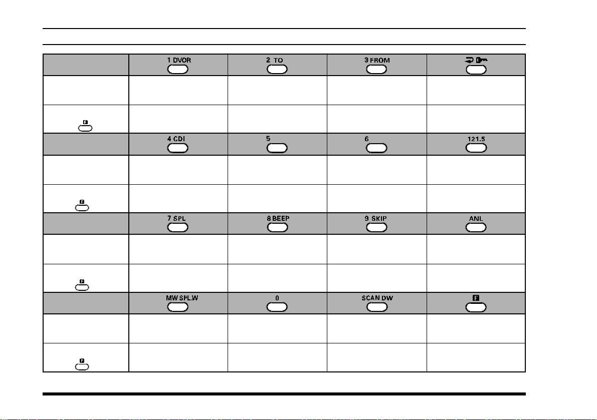
KEYPAD
Primary Function
(
Press Key
Secondary Function
(
Press +
Primary Function
(
Press Key
Secondary Function
(
Press +
Primary Function
(
Press Key
Secondary Function
(
Press +
Primary Function
(
Press Key
Secondary Function
(
Press +
)
)
)
)
)
)
)
)
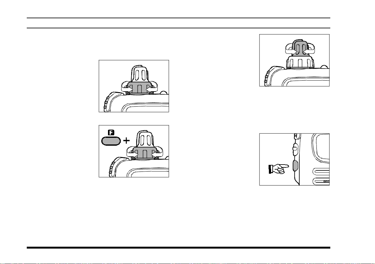
Frequency Entry
Digit 1
Activates DVOR mode
(page 25)
Frequency Entry
Digit 4
Activates Course
Direction Indicator mode
Frequency Entry
Digit 7
Activates Split (Duplex
mode on VOR
Memory “Write”
Command
Split-Memory “Write”
Command
Frequency Entry
Digit 2
Selects
“TO” VOR mode
Frequency Entry
Digit 5
None None None
Frequency Entry
Digit 8
)
On/Off Switch
for Keypad Beeper
Frequency Entry
Digit 0
Frequency Entry
Digit 3
Selects
“FROM” VOR mode
Frequency Entry
Digit 6
Frequency Entry
Digit 9
Allows Skipping of
Channel during Scan
Activates Scanning
Activates Dual Watch
Selects Memory Display
Type (page 19)
Locks the Keypad
Selects Emergency
Channel (121.5 MHz
Activates Automatic
Noise Limiter
None
Activates “Secondary”
Key mode
NoneNone
)
4
VXA-100 AVIATOR PILOT OPERATING MANUAL
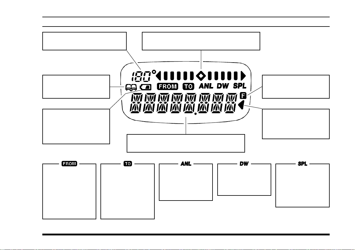
LCD DISPLA Y
This field displays the course
heading in degrees. See page 25.
This icon indicates that
the “Book” Memory Bank
is in use. See page 12.
This icon is the “Low Battery” indicator, which
blinks when the battery
voltage becomes too low
for proper operation.
This icon is used
during VOR navigation, to indicate that
the displayed information is based on
a course
VOR station. See
page 25.
from
the
This icon is used
during VOR navigation, to indicate that
the displayed information is based on
a course
station. See page
25.
This is the Course Deviation Indicator, used
during VOR Navigation. See page 24.
These digits provide frequency or alphanumeric
information about the channel you are using.
to
the VOR
This indicator confirms that the A
MATIC NOISE LIMITER is
activated. See page
15.
UTO-
This indicator confirms that D
WATCH is active. See
page 22.
This indicator confirms
that
Secondary
tion is active. See page 4.
This indicator confirms
that this channel will be
skipped during scan. See
page 21.
This indicator con-
UAL
firms that the “Split”
(Duplex) mode is
activated during
VOR operation. See
page 30.
Key Func-
VXA-100 AVIATOR PILOT OPERATING MANUAL
5
BEFORE YOU BEGIN
Precautions
r This apparatus is capable of two-way communi-
cation on channels used for critical aviation safety
communications. Therefore, it is important that
this radio be kept away from children or other
unauthorized users at all times.
r When making DC connections via the E-DC-5B
DC cable, be absolutely certain to observe the
proper voltage level and polarity guidelines. Do
not connect this radio directly to any 24 ~ 28
Volt DC source, nor to AC power of any kind.
Connecting the VXA-100 directly to a source
which exceeds 15.0 Volts DC will result in damage to the unit.
r Do not dispose of the Ni-Cd Battery Pack in a
fire. Do not carry a Ni-Cd Battery Pack in your
pocket, where keys or coins could short the terminals. This could create a serious fire/burn danger, and possibly cause damage to the Ni-Cd
pack.
r Although the VXA-100 is designed to be water
resistant, the enclosure is not “waterproof.” Do
not allow the radio to become submersed in water, and do not expose it and/or its Ni-Cd Battery
Pack to water spray under pressure.
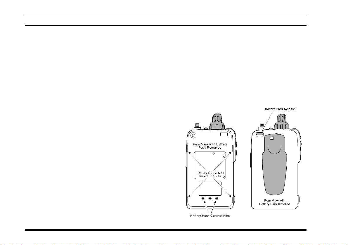
Battery Installation and Removal
Refer to the illustration below showing the rear panel
of the VXA-100 and its battery pack.
¦ Lay the battery pack loosely onto the rear panel
of the transceiver, and carefully mate the four
small alignment tabs on the battery with their corresponding insertion slots on the transceiver case.
Proper alignment occurs with the battery pack
offset about ½” from the top of the case.
6
VXA-100 AVIATOR PILOT OPERATING MANUAL
BEFORE YOU BEGIN
¦ Guide the pack into the slots with a slight in-
ward pressure, then slide the battery pack upward, until it locks in place with a “Click.”
¦ To remove the battery, turn the radio off and re-
move any protective cases. Press in the Battery
Release button (behind the Antenna jack) while
sliding the battery down ½”. Then lift the battery away.
Do not attempt to open any of the recharge-
able Ni-Cd packs, as personal injury or damage to the Ni-Cd pack could occur if a cell or cells
become accidentally short-circuited.
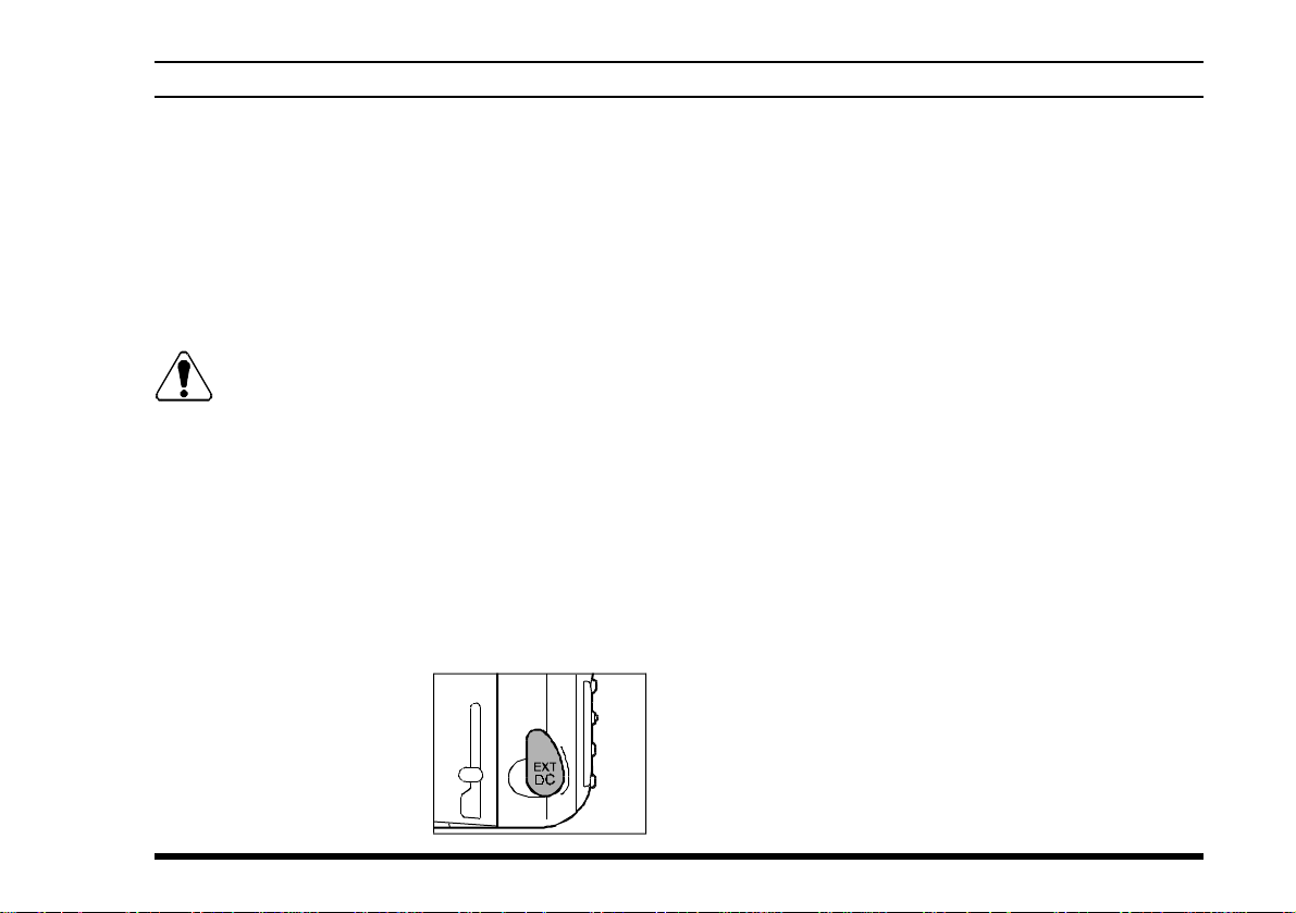
Battery Charging
It is necessary to fully charge the Ni-Cd battery before it’s first use. Follow these procedures:
¦ Install the supplied FNB-41 Ni-Cd battery pack
onto the transceiver. Ensure that the transceiver
is switched off.
¦ Lift up the rubber cover
to expose the EXT DC
jack. Plug the cable plug
from the NC-60 charger
into this jack.
¦ Plug the NC-60 into the
AC mains outlet.
¦ Allow a minimum of 10 hours for the FNB-41
to reach full charge. Leave the transceiver
switched off this entire period.
¦ Unplug the cable from the EXT DC jack. Re-
place the rubber cover to protect the jack. Switch
on the transceiver and begin operation.
Important Notes:
r Do not leave the charger connected to the trans-
ceiver for continuous periods in excess of 24
hours. Long term overcharging can degrade the
Ni-Cd battery pack and significantly shorten its
useful life.
r If using a charger other than the NC-60, or if
using a battery pack other than the FNB-41, follow the appropriate instructions provided with
the charger/battery. Contact your Dealer if you
have any doubts about the appropriateness of the
particular charger or battery pack you intend to
use.
VXA-100 AVIATOR PILOT OPERATING MANUAL
7
BEFORE YOU BEGIN
Low Battery Indication
¦ As your battery discharges during use, the volt-
age will gradually become lower. When the battery voltage reaches 5.0 Volts, the “ x ” icon
will blink on the LCD display, indicating that
the battery pack must be recharged before further use.
¦ Avoid recharging Ni-Cd batteries before the
“Low Battery” indicator is observed, as this can
degrade the charge capacity of your Ni-Cd battery pack. Yaesu recommends that you carry an
extra, fully-charged pack with you so you will
not lose communications capability due to a depleted Ni-Cd battery.
This “deep
cycling”
practice will
help to maintain longer
overall battery life after
many recharging
cycles.
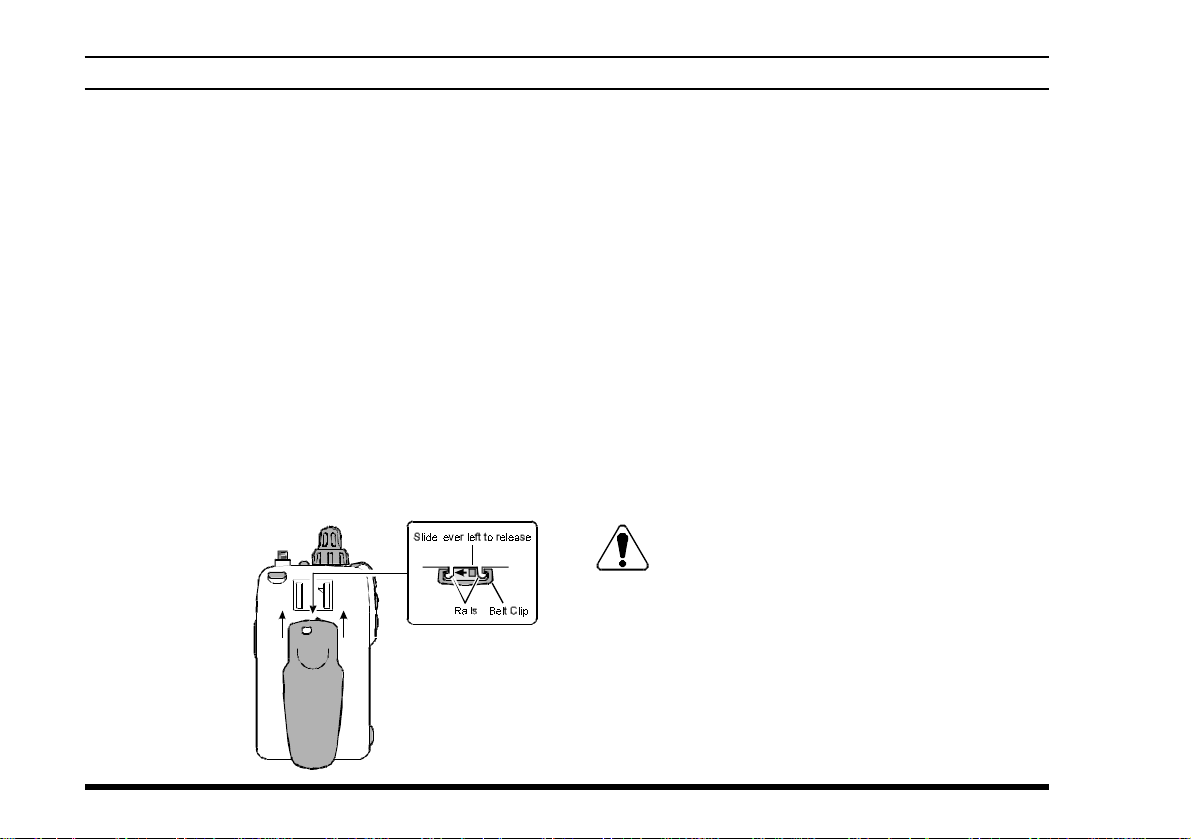
Belt Clip Installation
Installing the FBA-21 (option) Alkaline
Battery Case
The optional FBA-21 Battery Case allows operation of the VXA-100 using six “AA” size Alkaline
batteries.
To open the FBA-21 Battery Case, hold it in your
left hand, and slide the release catch downward with
your right index finger.
When installing batteries, insert the (–) end first, then
press in the (
Always replace all six batteries at the same time, paying attention to the polarity indicated inside the case.
The batteries can be ejected by pulling upward on
the strip.
tain the thermal and over-current protection circuits (provided in the “FNB” series of Ni-Cd Battery Packs) required when utilizing Ni-Cd cells.
++
+) end so the battery snaps into place.
++
The FBA-21 must not be used with rechargeable cells. The FBA-21 does not con-
8
VXA-100 AVIATOR PILOT OPERATING MANUAL
OPERATION
Preliminary Steps
¦ Install a charged battery pack onto the transceiver ,
as described previously.
¦ Screw the supplied antenna onto the Antenna
jack. Never operate this transceiver without an
antenna connected.
¦ If you have an optional Speaker/Microphone or
headset, we recommend that it not be connected
until you are familiar with the basic operation of
the VXA-100.
Operation Quick Start
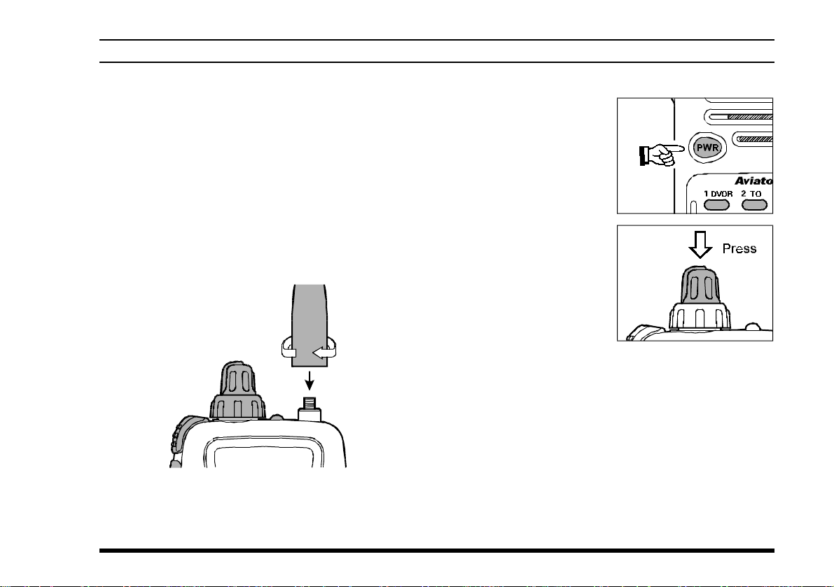
r To turn the radio on,
press and hold the
PWR switch for ½
second.
r After three “initial-
ization” beeps are
heard, a channel frequency should appear on the display. If
not, press downward
(momentarily) on the
(inner) VOLUME knob (repeatedly , if necessary)
so that “
lowed by a channel frequency.
r Directly entering frequencies from the Keypad
is the easiest method if you know the frequency
on which you wish to operate. Just enter the five
digits of the frequency to move to that frequency .
For example, to set 134.35 MHz,
press [1] à [3] à [4] à [3] à [5].
" VFO "
” appears on the display, fol-
VXA-100 AVIATOR PILOT OPERATING MANUAL
9
OPERATION
To set 118.275 MHz, you do not need to press
the final “5” in the frequency:
[1]
à [1] à [8] à [2] à [7].
r You may also turn
the top panel’s (outer
ring) CHANNEL selector knob to choose
the desired operating
frequency . The channel frequency will
appear on the LCD.
r T o change frequency
in 1 MHz steps, press
the [F] key momentarily, then rotate the
CHANNEL selector
knob to select the
MHz digit desired.
Press [F] once more to resume normal channel
selection in 25-kHz steps.
r If you enter a frequency in the “NAV” band (108-
117.975 MHz), the “VOR” operating mode will
be selected.
r Rotate the VOL-
UME knob to set the
volume level. If no
signal is present,
press and hold the
MONITOR button
for 2 seconds; background noise will now be heard, and you may
use this noise to set the VOLUME knob for the
desired audio level. Press the MONITOR button
momentarily , to silence the noise and resume normal (quiet) monitoring.
r Press and hold the
LAMP button for 2
seconds, to illuminate the display and
keypad continuously .
T o disable the illumination, press the
LAMP button momentarily.
r To turn the radio off, press and hold in the PWR
switch for 2 seconds.
10
VXA-100 AVIATOR PILOT OPERATING MANUAL
 Loading...