

Yaesu VX-8GE Operating Manual
144/430 MHz
DUAL BAND FM TRANSCEIVER
WITH GPS
VX-8GE
OPERATING MANUAL
VERTEX STANDARD CO., LTD.
4-8-8 Nakameguro, Meguro-Ku, Tokyo 153-8644, Japan
VERTEX STANDARD
US Headquarters
10900 Walker Street, Cypress, CA 90630, U.S.A.
YAESU UK LTD.
Unit 12, Sun Valley Business Park, Winnall Close
Winchester, Hampshire, SO23 0LB, U.K.
VERTEX STANDARD HK LTD.
Unit 5, 20/F., Seaview Centre, 139-141 Hoi Bun Road,
Kwun Tong, Kowloon, Hong Kong
VERTEX STANDARD (AUSTRALIA) PTY., LTD.
Normanby Business Park, Unit 14/45 Normanby Road
Notting Hill 3168, Victoria, Australia

Contents
Introduction ................................................................................. 1
Controls &Connections ............................................................... 2
Display Icons & Indicators ......................................................... 3
Keypad Functions ....................................................................... 4
Accessories & Option .................................................................. 6
Accessories Supplied with the VX-8GR .................................. 6
Available Options for your VX-8GR ....................................... 7
Installation of Accessories ........................................................... 8
Antenna Installation ................................................................. 8
Belt Clip Installation ................................................................ 8
Installation of FNB-101LI Battery Pack .................................. 9
Battery Life Information ........................................................ 10
Installation of FBA-39 Alkaline Battery Case ....................... 11
Interface of Packet TNCs .......................................................... 12
Operation ................................................................................... 13
Switching Power On and Off ................................................. 13
Adjusting the Volume Level .................................................. 13
Squelch Adjustment ............................................................... 14
Selecting the Operating Band ................................................ 15
Selecting the Frequency Band ................................................ 16
Frequency Navigation ............................................................ 17
Sub Band Operation ......................................................... 17
1) Tuning Dial .................................................................. 17
2) Direct Keypad Frequency Entry .................................. 17
3) Scanning ....................................................................... 18
Transmission .......................................................................... 19
Changing the Transmitter Power Level ............................ 19
Advanced Operation ................................................................. 21
Keyboard Locking ................................................................. 21
Adjusting the Keypad Beeper Volume Level ......................... 22
Setting the Frequency Display Image Size ............................. 22
Audio Muting ......................................................................... 23
Keypad/LCD Illumination ...................................................... 23
Changing the Channel Steps .................................................. 24
Changing the Receiving Mode ............................................... 24
SQL S-meter .......................................................................... 25
Repeater Operation ................................................................... 26
General ................................................................................... 26
Repeater Shifts ....................................................................... 26
Automatic Repeater Shift (ARS) ........................................... 26
Manual Repeater Shift Activation .......................................... 27
Changing the Default Repeater Shifts .............................. 27
Checking the Repeater Uplink (Input) Frequency ................. 28
CTCSS/DCS/EPCS Operation ................................................. 29
CTCSS Operation .................................................................. 29
DCS Operation ...................................................................... 30
DCS Code Inversion ........................................................ 32
Tone Search Scanning ........................................................... 34
EPCS (Enhanced Paging & Code Squelch) ........................... 35
Storing the CTCSS Tone Pairs for EPCS Operation ....... 35
Activating the Enhanced Paging & Code Squelch System .. 36
Paging Answer Back ........................................................ 36
CTCSS/DCS/EPCS Bell Operation ....................................... 37
Programming the User Melody ........................................ 38
Split Tone Operation .............................................................. 39
CTCSS/DCS/EPCS Vibrator Operation ................................ 40
Tone Calling (1750 Hz) ......................................................... 41
Memory Mode (Regular Memory Channel Operation) ......... 42
Memory Storage .................................................................... 43
Storing Independent Transmit Frequency (“Odd Splits”) ... 44
Memory Recall ....................................................................... 44
HOME Channel Memory ....................................................... 45
Labeling Memories ................................................................ 46
Memory Offset Tuning .......................................................... 47
Masking Memories ................................................................ 48
Memory Bank Operation ....................................................... 49
Assigning Memories to a Memory Bank .......................... 49
Memory Bank Recall ........................................................ 49
Removing Memories from a Memory Bank ..................... 50
Changing a Memory Bank’s Name .................................. 50
Moving Memory Data to the VFO ........................................ 51
Memory Only Mode ............................................................... 51
Memory Mode (Special Memory Channel Operation) .......... 52
Weather Broadcast Channels ................................................. 52
VHF Marine Memory Channels ............................................. 53
Scanning ..................................................................................... 54
General ................................................................................... 54
VFO Scanning ........................................................................ 56
How to Skip (Omit) a Frequency during VFO Scan ........ 57
Memory Scanning .................................................................. 58
How to Skip (Omit) a Channel during Memory Scan ...... 59
Preferential Memory Scan ................................................ 59
Memory Bank Scan .......................................................... 61
Programmable (Band Limit) Memory Scan (PMS) ............... 62
“Priority Channel” Scanning (Dual Watch) ........................... 63
Priority Revert Mode ....................................................... 64
Automatic Lamp Illumination on Scan Stop .......................... 65
Band Edge Beeper ................................................................. 65
GPS Operation .......................................................................... 66
Setting the Time Zone (Time Offset) ..................................... 67
Selecting the Display Units of the GPS Screen ...................... 68
Selecting the Map Datum ...................................................... 68
APRS® Operation ...................................................................... 70
Preparations ........................................................................... 70
Receiving an APRS Beacon ................................................... 73
Transmit an APRS Beacon .................................................... 76
Receiving an APRS Message ................................................. 79
Transmit an APRS Message .................................................. 81
ARTSTM (Automatic Range Transponder System) ................ 83
Basic ARTSTM Setup and Operation ..................................... 84
ARTSTM Polling Time Options .............................................. 84
ARTSTM Alert Beep Options ................................................. 85
CW Identifier Setup ............................................................... 86
Spectrum Analyzer Operation ................................................. 87
Smart Search Operation ........................................................... 88
Message Feature ........................................................................ 90
General ................................................................................... 90
Programming a Message ........................................................ 90
Programming a Member List ................................................. 91
Set your Personal ID .............................................................. 92
Sending a Message ................................................................. 93
Receiving a Message .............................................................. 94
Emergency Feature ................................................................... 95
Emergency Channel Operation .............................................. 95
Emergency Automatic ID (EAI) feature ................................ 96
Selecting the EAI mode and its Transmit Time ................ 97
Activating the EAI feature ............................................... 97
To Locate an Unresponsive Operator
using the EAI feature ............ 98
Internet Connection Feature .................................................... 99
General ................................................................................... 99
SRG (“Sister Radio Group”) Mode ....................................... 99
FRG (“Friendly Radio Group”) Mode ................................. 100
DTMF Operation .....................................................................102
CW Learning Feature ............................................................. 104
CW Training Feature .............................................................. 106
Sensor Mode ............................................................................. 107
Clock Set ............................................................................. 107
Miscellaneous Setting .............................................................. 108
Password .............................................................................. 108
Programming the d Key .................................................. 110
ATT (Front End Attenuator) ............................................... 111
Receive Battery Saver Setup ............................................... 112
TX Battery Saver ................................................................. 112
Disabling the BUSY Indicator ............................................. 113
Automatic Power-Off (APO Feature) .................................. 113
Transmitter Time-Out Timer (TOT) .................................... 114
ON/OFF Preset Timer .......................................................... 115
Busy Channel Lock-Out (BCLO) ........................................ 116
Changing the TX Deviation Level ....................................... 116
Changing the Microphone Gain ........................................... 117
S-and TX Power Meter Symbols ......................................... 117
Display Contrast .................................................................. 118
Display Dimmer ................................................................... 118
My Bands Operation ............................................................ 119
Changing the Status of the g Key .................................... 120
Reset Procedures ..................................................................... 121
Cloning ..................................................................................... 122
Set Mode ................................................................................... 124
APRS/GPS Set Mode .............................................................. 148
Specifications ........................................................................... 160
Appendix (Computer Connections) ....................................... 162

INTRODUCTION
The Ultra Compact VX-8GE (60 x 95 x 28 mm: W x H x D) is equipped with a GPS receiver
and
thinner than the previous advanced model - It is packed with advanced technology and
features, designed for outdoor operation. It is submersible (IPX5) and shockproof! The compact case combines a rugged die-cast chassis with the clean, tough polycarbonate resin front
panel. Its shockproof versatility will allow you to operate the radio in the toughest environments.
The large High-resolution Dot Matrix LCD display provides clear, easy-to-read indication of
both “A” (Main band) and “B” (Sub band) frequencies, the operating mode, and S-meters for
both bands. When you engage the Spectrum Scope function, the high-resolution display will
indicate relative signal strengths of up to ±50 adjacent channels!
The built-in worldwide standard AX.25 Data TNC Modem permits uncomplicated APRS
operation. (Automatic Packet/Position Reporting System: APRS® is a registered trademark of
the APRS Software and Bob Bruninga, WB4APR.) The VX-8GE supports APRS
bps data communication on the “B” (Sub band) band only. You may communicate your location to other APRS
radio! You and others will be able to see your APRS
®
stations along with the position, speed and heading displayed on your
®
movement on the web! The VX-8GE
displays the received station’s positions, heading directions, messages, distances, icons (43
kinds), weather information, object, etc. With the list function you may automatically store and
recall up to 30 messages and the APRS
Unit provides you with real time APRS
®
data from up to 50 stations. The built-in GPS Receiver
®
data.
Enhanced Paging and Code Squelch (EPCS) allow you to page a particular station and only
receive calls from that station. A security Password may be set, which will allow you to turn on
and operate the transceiver only after you enter the Password. A convenient key provides access to Vertex Standard’s WIRES™ (Wide-Coverage Internet Repeater Enhancement System).
The Emergency Automatic ID (EAI) function can automatically cause your VX-8GE to transmit your callsign and engage your rig’s microphone, even if you are disabled and unable to
press the PTT switch. Additional features include: transmit Time-Out Timer (TOT), Automatic
Power-Off (APO), and Automatic Repeater Shift (ARS). Yaesu’s exclusive ARTS™ (AutoRange Transponder System) which “beeps” the user when you move out of communications
range with another ARTS™ equipped station. There is provision to reduce the TX deviation for
use in areas of high channel congestion. The squelch circuit allows adjusting the squelch to
open at a programmable setting of the S-Meter, thus reducing guesswork in setting the squelch
threshold. Provides a DATA jack which enables the display of location data (Lat/Lon) from an
after-market GPS receiver, and outputs the location data (Lat/Lon) of the built-in GPS receiver
unit and the Waypoint data of the received APRS beacons.
We appreciate your purchase of the VX-8GE, and encourage you to read this manual thoroughly, and learn about the many exciting features of your thrilling new Yaesu hand-held
transceiver!
®
1200/9600
®
VX-8GE OPERATING MANUAL 1
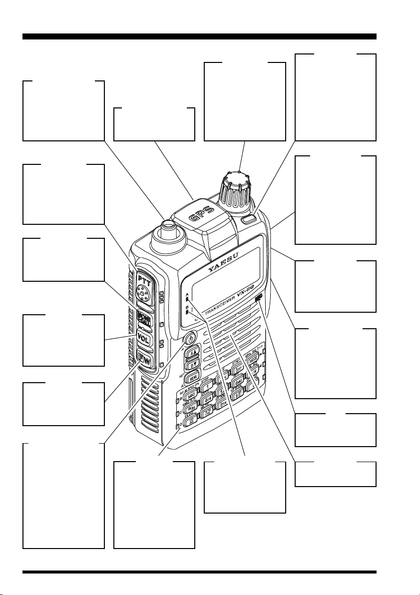
CONTROLS & CONNECTIONS
ANTENNA Jack
Connect the supplied rubber flex antenna (or another
antenna presenting
a 50-Ohm impedance) here.
PTT Switch
(“Push To Talk”)
Press this switch inward to transmit, and
release it (to receive)
after your transmission is completed.
T.CALL Key
Pressing this key
activates the T.CALL
(1750 Hz) for repeater access.
VOL Key
Rotate the DIAL
knob while pressing
and holding this key
to adjust the audio
volume level.
F/W Key
Pressing this key
activates the “Alternate” key functions
of the keypad.
(
p
PWR) Switch
Press and hold this
switch for 2 seconds
to toggle the
transceiver’s power
“on” and “off”.
Press this switch
briefly while the
transceiver is turned
“on” to toggle the key
lockout feature “on”
or “off”.
GPS RECEIVER
The internal GPS receiver is located
hear.
KEYPAD
The 18 front panel
key buttons select
many of the most important operating
features.
The functions of the
keys are described
in detail on pages 4
and 5.
DIAL Knob
The main tuning Dial
is used to set the operating frequency,
and is also used for
audio volume level,
menu selections,
and other adjustments.
TX/BUSY Lamps
These indicators
glow green when a
signal is being received and red when
transmitting.
LED Light
This white LED will
glow (or flash) during
“Emergency Channel” operation. It can
also be useful as a
flash light in a dark
environment via the
Set Mode Item 45
LED LIGHT.
MIC/SP Jack
This four conductor
miniature jack allows
connection of an optional MH-34B4B
Speaker Microphone, MH-37A4B
Ear piece/Microphone, or VC-25
VOX Headset.
DATA Jack
This three conductor
2.5-mm jack provides connection
points for an External computer.
EXT DC Jack
This coaxial DC jack
allows connection to
an external DC
power source (7.4 12 V DC). The center pin of this jack is
the Positive (+) line.
MIC
The internal microphone is located
here.
SPEAKER
The internal speaker
is located here.
VX-8GE OPERATING MANUAL2
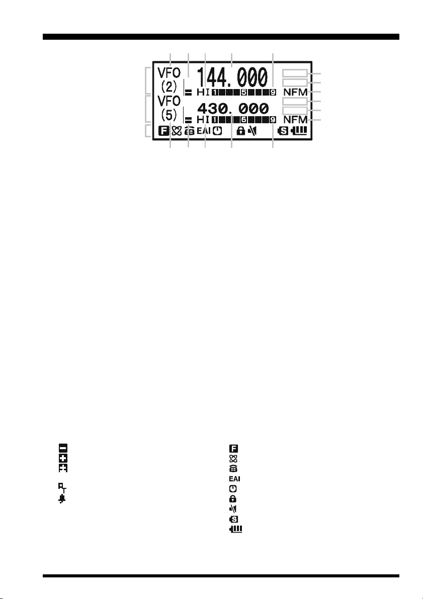
DISPLAY ICONS & INDICATORS
“A” Band
Display
“B” Band
Display
Icon
FREQUENCY CONTROL
VFO: VFO Mode
MR: Memory Mode
TUN: Memory Tune Mode
HOM: Home Channel Memory
PMS: Programmable Memory Scan Mode
VDW: Dual Watch Active
(VFO-Memory Channel)
MDW:Dual Watch Active
(Memory Channel-Memory Channel)
SMS: Smart Search Active
Note: When these icons blink, the Sub Band Operation features are active.
SQUELCH TYPE & RADIO MODE
TN: Tone Encoder Active
TSQ: Tone Squelch Active
DCS: Digital Code Squelch Active
RTN: Reverse Tone Squelch Active
PR: User Programmed Reverse CTCSS Decoder Active
PAG : Enhanced Paging & Code Squelch (EPCS) Active
MSG: Message Feature Active
DC: Split Tone Feature Active (DCS Encode only)
T-D: Split Tone Feature Active (Encodes a CTCSS Tone and Decodes a DCS Code)
D-T: Split Tone Feature Active (Encodes a DCS Code and Decodes a CTCSS Tone)
A12:APRS® Feature Active (1200 bps)
A96:APRS® Feature Active (9600 bps)
MISCELLANEOUS SETTING
: Repeater Shift Direction (Minus Shift)
: Repeater Shift Direction (Plus Shift)
: Independent Transmit Frequencies
(Odd Splits)
: Attenuator Active
: Bell Alarm Active
OPERATING MODE
NFM: FM
AM: AM
Note 1): When a bar is shown under these icons, the Vibrator function is active.
2): When a dashed bar is shown under these icons, the CTCSS/DCS/EPCS Vibrator function is active.
3): When a short-dashed bar is shown under these icons, the APRS Message Vibrator function is active.
VOLUME LEVEL
TX POWER LEVEL
HI: High Power (5 W)
L3: LOW3 Power (2.5 W)
L2: LOW2 Power (1 W)
L1: LOW1 Power (0.02 W)
OPERATING FREQUENCY
S&PO METER
ICON
: Secondary Keypad Active
: Internet Connection Feature (WiRESTM) Active
: DTMF Autodialer Active
: Emergency Automatic ID (EAI) Feature Active
: Automatic Power-Off Active
: Key Lock Active
: Mute Feature Active
: Battery Saver Active
: Battery Indicator
VX-8GE OPERATING MANUAL 3
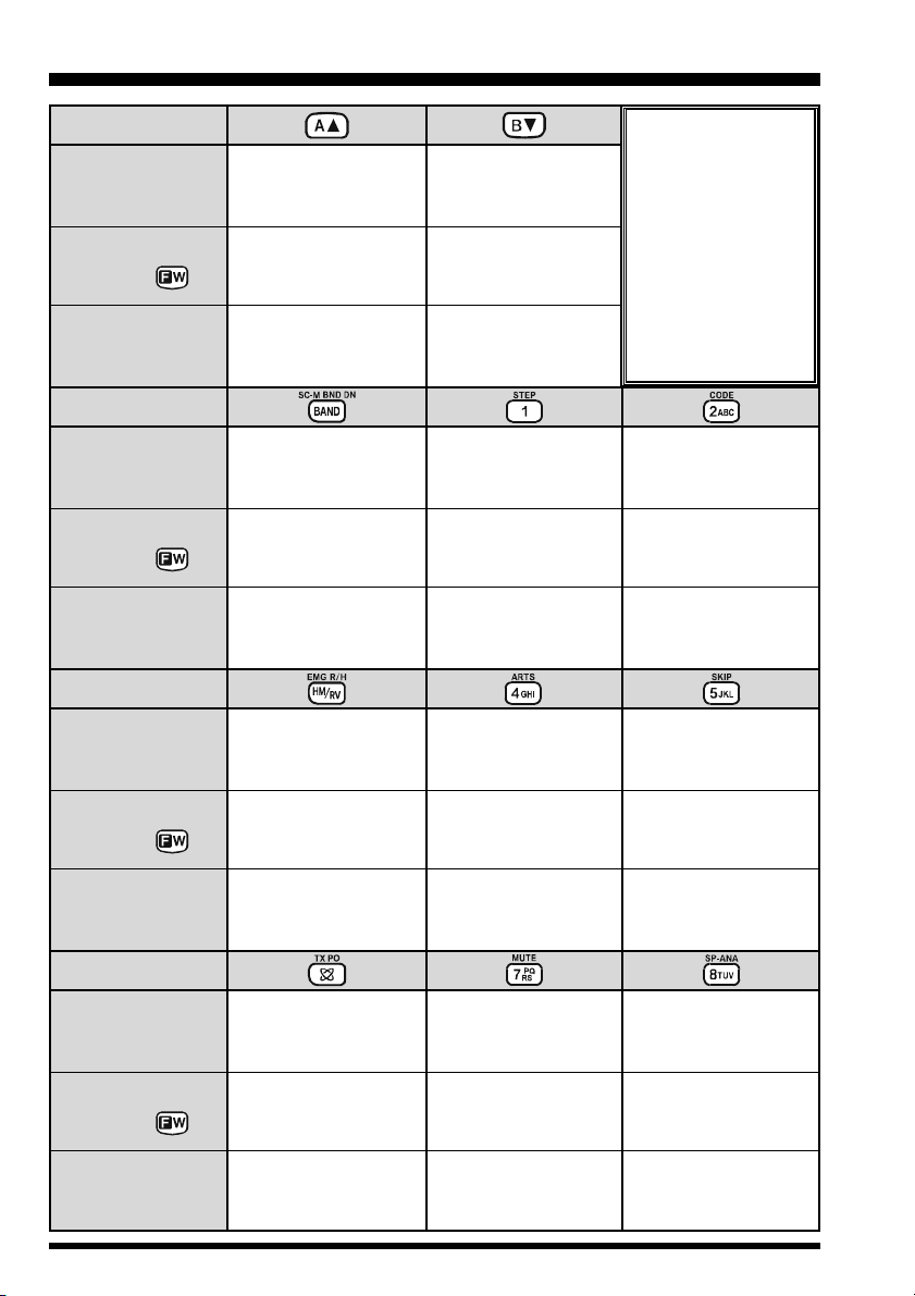
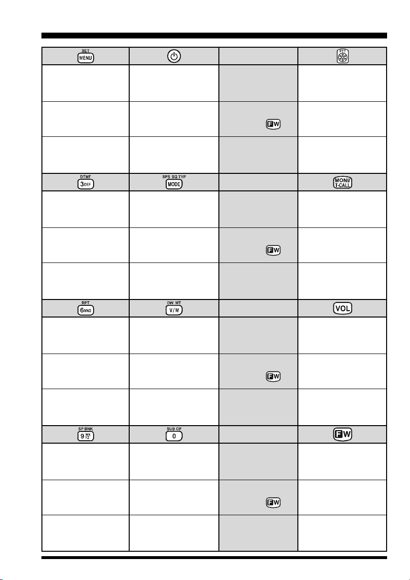
KEYPAD FUNCTIONS
PRIMARY FUNCTION
(
PRESS KEY
)
SECONDARY FUNCTION
(
PRESS +
THIRD FUNCTION
(
PRESS AND HOLD KEY
PRIMARY FUNCTION
(
PRESS KEY
)
SECONDARY FUNCTION
(
PRESS +
THIRD FUNCTION
(
PRESS AND HOLD KEY
PRIMARY FUNCTION
(
PRESS KEY
)
Switches the “Upper”
frequency to be the
“Operating” (TX) Band.
)
)
(2) Activates the Memory Bank
)
)
No Action
Activates the
Dual Receive Feature.
(1) Moves operation to the
next-highest frequency band.
feature.
Moves operation to the
next-lowest frequency band
(1) Select the Bandwidth for
the VFO scanner.
(2) Select the Memory Scan
mode.
Reverses transmit and
receive frequencies while
working through a repeater.
Switches the “Lower”
frequency to be the
“Operating” (TX) Band.
No Action
Activates the
Dual Receive Feature.
Frequency entry digit “1”
Selects the synthesizer steps
to be used during VFO
operation.
No Action
Frequency entry digit “4”
DCS code, EPCS code, or
NOTE
Press the a or b
key to switch the frequency display between
the “Double-size Character” and “Small Character”
mode while in Mono band
operation.
Frequency entry digit “2”
Selects the CTCSS Tone,
Message.
No Action
Frequency entry digit “5”
SECONDARY FUNCTION
(
PRESS +
THIRD FUNCTION
(
PRESS AND HOLD KEY
PRIMARY FUNCTION
(
PRESS KEY
)
SECONDARY FUNCTION
(
PRESS +
THIRD FUNCTION
(
PRESS AND HOLD KEY
Switches operation to the
“Home” (favorite frequency)
)
)
)
)
channel.
Activates the EMERGENCY
function.
Activates the Internet
Connection feature.
Selects the desired transmit
power output level.
No Action.
Activates the ARTS feature.
No Action
Frequency entry digit “7”
Activates the Audio Mute
Feature.
No Action No Action
VX-8GE OPERATING MANUAL4
Activates the Memory Scan
“Skip” channel selection
mode.
No Action
Frequency entry digit “8”
Activates the Spectrum
Analyzer (Spectra-ScopeTM)
feature.
KEYPAD FUNCTIONS
Activate the APRS
(Automatic Position
Reporting System) function.
No Action
Enter the Set Mode.
Frequency entry digit “3”
Selects the DTMF mode.
No Action
Frequency entry digit “6”
Selects the direction of the
uplink frequency shift (either
“–”, “+”, or “simplex”) during
repeater operation.
No Action
Toggle the key lock feature
“on” and “off” while the
transceiver is turned “on”.
No Action
Toggle the transceiver’s
power “on” and “off”.
Selects the receive mode
between AM and FM.
Activates the CTCSS
or DCS operation.
Engage the Special
Search mode.
Switches frequency control
between the VFO and
Memory System.
Activates the “Memory Tune”
mode while in the Memory
Recall mode.
Activates the Priority (Dual
Watch) function.
PRIMARY FUNCTION
(
PRESS KEY
)
SECONDARY FUNCTION
(
PRESS +
)
THIRD FUNCTION
(
PRESS AND HOLD KEY
PRIMARY FUNCTION
(
PRESS KEY
)
SECONDARY FUNCTION
(
PRESS +
)
THIRD FUNCTION
(
PRESS AND HOLD KEY
PRIMARY FUNCTION
(
PRESS KEY
)
SECONDARY FUNCTION
(
PRESS +
)
THIRD FUNCTION
(
PRESS AND HOLD KEY
Activates the transmitter.
Activates the transmitter
temporarily in “high” power,
while the transceiver is in
“low” power operation.
Activates the Transmitter.
)
Activates the T.CALL (1750
Hz) for repeater access.
Adjusts the Squelch
threshold level.
Activates the T.CALL (1750
)
Hz) for repeater access.
No Action
Toggle the DIAL knob
function between the
“Frequency Control” and
“Receiver Audio Control”.
Rotate the DIAL knob while
holding this key to adjust the
)
audio volume level.
Frequency entry digit “9”
Enters the “Special Memory”
mode.
No Action No Action
Frequency entry digit “0”
Activates the Sub Band
Operation feature.
PRIMARY FUNCTION
(
PRESS KEY
)
SECONDARY FUNCTION
(
PRESS +
THIRD FUNCTION
(
PRESS AND HOLD KEY
Activates the “Secondary”
key function.
Disables the “Secondary”
)
)
key function.
Activates the “Memory Write”
mode (for memory channel
storage).
VX-8GE OPERATING MANUAL 5

ACCESSORIES & OPTIONS
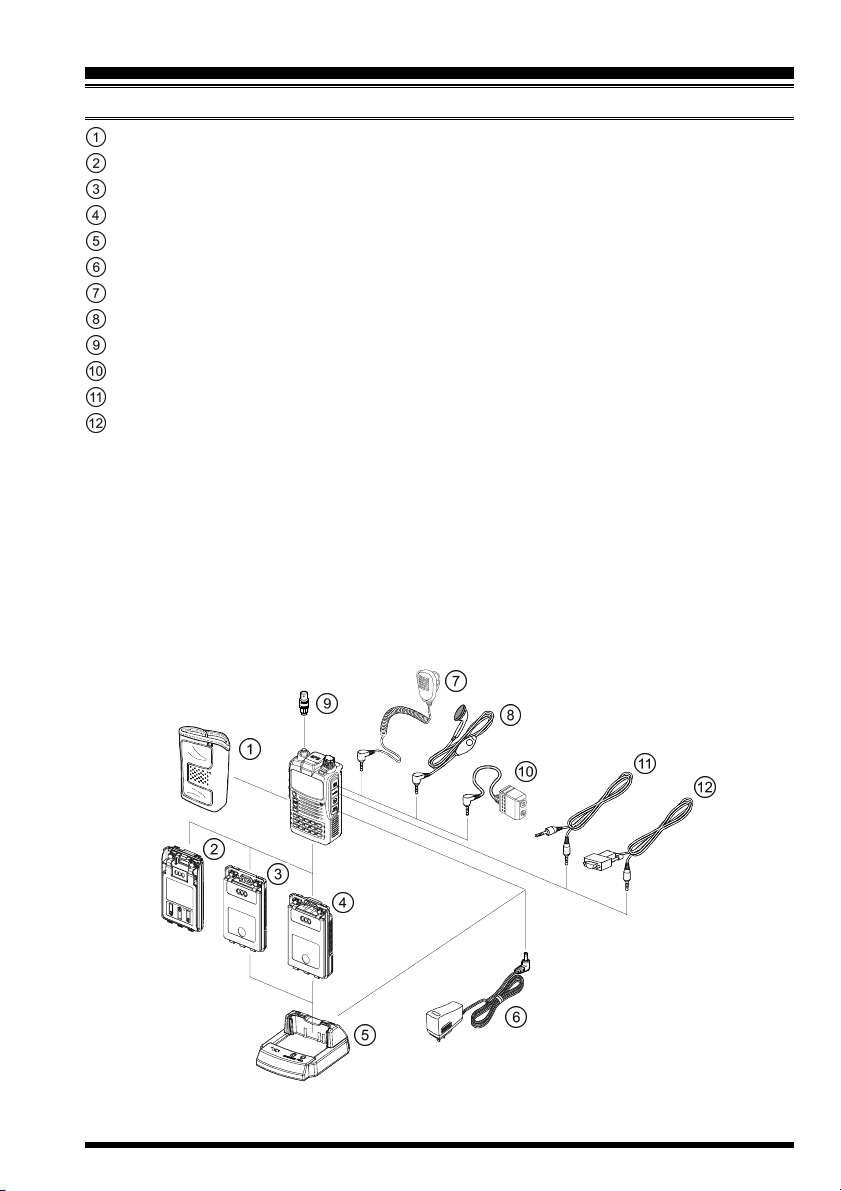
ACCESSORIES SUPPLIED WITH THE VX-8GE
Antenna 1 pc YHA-72 (Q3000236)
Li-Ion Battery Pack 1 pc FNB-101LI (7.4V/1,100mAh: AAG10X001)
Battery Charger 1 pc PA-44C (230 VAC, Type-C plug: Q9500165) or
PA-44U (230 VAC, Type-BF plug: Q9500166)
Belt Clip 1 pc (RA1053600)
Screws 2 pcs (M3x10SUS: U24310020)
Plastic Cap 1 pc (RA1054200)
Sheet 1 pcs (RA1231300)
Operating Manual 1 pc
Warranty Card 1 pc
VX-8GE OPERATING MANUAL6
ACCESSORIES & OPTIONS
AVAILABLE OPTIONS FOR YOUR VX-8GE
CSC-95 Soft Case
FBA-39 3 x “AA” Cell Battery Case (batteries not supplied)
FNB-101LI Li-Ion Battery Pack (7.4V/1,100 mAh)
FNB-102LI Li-Ion Battery Pack (7.4V/1,800 mAh)
CD-41 Rapid Charger (requires PA-44B/C/U)
PA-44B/C/UBattery Charger for the CD-41
CN-3 BNC-to-SMA Adapter
MH-34B4B Speaker/Microphone
MH-37A4B Ear peace Microphone
CT-44 Microphone Adapter
CT-144 Clone Cable
CT-143 PC Connection Cable
: “B” suffix is for use with 120 VAC (Type-A plug), “C” suffix is for use with 230 VAC
(Type-C plug), and “U” suffix is for use with 230 VAC (Type-BF plug).
Availability of accessories may vary. Some accessories are supplied as standard per local
requirements, while others may be unavailable in some regions. Consult your Yaesu Dealer
for details regarding these and any newly-available options. Connection of any non-Yaesu
approved accessory, should it cause damage, may void the Limited Warranty on this apparatus.
VX-8GE OPERATING MANUAL 7
INSTALLATION OF ACCESSORIES
ANTENNA INSTALLATION
The supplied antenna provides good results over the entire frequency range of the transceiver. However, for enhanced base station medium-wave and shortwave reception, you
may wish to connect an external (outside) antenna.
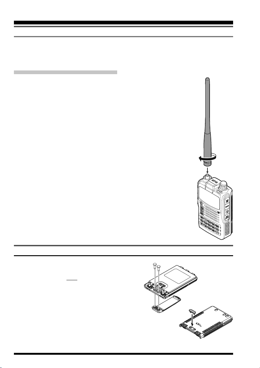
TO INSTALL THE SUPPLIED ANTENNA
Hold the bottom end of the antenna, then screw it onto the mating connector on the transceiver until it is snug. Do not over-tighten by use of extreme force.
Notes:
Never transmit without having an antenna connected.
Carefully turn the supplied antenna onto the SMA jack. Never twist
the upper part of the antenna while screwing it onto the mating connector of the transceiver.
If using an external antenna for transmission, ensure that the SWR
presented to the transceiver is 1.5:1 or lower.
BELT CLIP INSTALLATION
Install the supplied Belt Clip to the FNB-101LI
Battery Pack using the supplied two screws
(Figure 1). Use only the screws included with
the Belt Clip to mount the Belt Clip to the back
of the Battery Pack!
If you do not need the Belt Clip, install the sup-
plied Plastic Cap to the Battery Pack (Figure
2). If you install the belt clip later, push the Plastic Cap out with a small tool or screwdriver.
Figure 1
Figure 2
VX-8GE OPERATING MANUAL8
INSTALLATION OF ACCESSORIES
INSTALLATION OF FNB-101LI BATTERY PACK
The FNB-101LI is a high-performance Lithium-Ion battery providing high capacity in a
very compact package. Under normal use, the FNB-101LI may be used for approximately 300 charge cycles, after which operating time may be expected to decrease. An old
battery pack, which is displaying diminished capacity should be replaced with a new one.
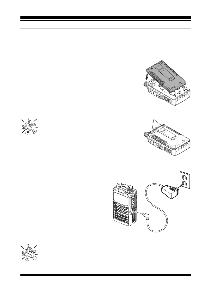
To install the FNB-101LI Battery Pack, carefully mate the
battery’s three alignment tabs with their corresponding alignment slots on the transceiver bottom case, then gently press
the top side of the Battery Pack until it locks in place with a
“click”.
To remove the Battery Pack, turn the transceiver off and
remove any protective cases. Press the Battery Pack Release Knobs downward to unlock the latch, then remove
the Battery Pack from the transceiver.
1) The VX-8GE battery must be correctly installed,
to maintain the waterproof integrity.
2) Always use the Vertex Standard Co., Ltd. Model
FNB-101LI or FNB-102LI Lithium-Ion Battery Pack.
3) Battery Pack shall not be exposed to excessive heat such as
sunshine, fire, or the like.
4) Risk of explosion if battery is replaced by an incorrect type.
Dispose of used batteries according to the instructions
BATTERY PACK RELEASE KNOB
INSTALL
REMOVE
If the battery has never been used, or its charge
is depleted, it may be charged by connecting
the PA-44B/C Battery Charger, as shown in
the illustration, to the EXT DC jack.
While the battery is being charged, the display
will indicate “CHARGING” and the “A” indicator will glow red. The S-meter will deflect according to the charging status. When charging
is finished, the display will change to indicate
“COMPLETE” and the “A” indicator will glow
green.
1) Turn the radio off while charging the battery.
2) Perform the battery charging where the ambient temperature range +5 °C
to +35 °C. Charge out of this range could cause damage to the battery pack.
3) Use only the Vertex Standard Co., Ltd. Model PA-44C/U Battery Charger.
VX-8GE OPERATING MANUAL 9
INSTALLATION OF ACCESSORIES
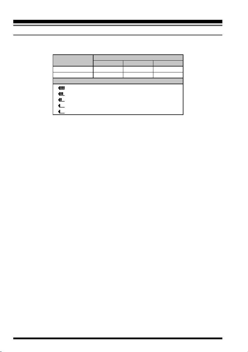
BATTERY LIFE INFORMATION
When the battery charge is almost depleted, a “Low Voltage” indicator will appear on the
display. When this icon appears, it is recommended that you charge the battery soon.
OPERATING BAND
144 MHz
430 MHz
: Full battery power
: Enough battery power
: Low battery power
: Poor battery power
(
w/Blink): Charge (or replace) the battery
TX 6 seconds, RX 6 seconds, and Squelched 48 seconds (continuous operating cycle).
GPS receiver is “off”.
FNB-101LI
BATTERY LIFE (APPROX.
FNB-102LI
5.0 hours
5.0 hours
BATTERY INDICATOR
8.5 hours
8.0 hours
The present battery voltage can be displayed manually on the LCD, by following the
instructions on page 107.
Battery capacity may be reduced during extremely cold weather. Keeping the radio inside
your parka may help preserve the full charge capacity.
)
FBA-39
17 hours
16 hours
VX-8GE OPERATING MANUAL10
INSTALLATION OF ACCESSORIES
INSTALLATION OF FBA-39 ALKALINE BATTERY CASE (OPTION
The optional FBA-39 Battery Case allows receive monitoring using three “AA” size Alkaline batteries. Alkaline batteries can also be used for low power transmission in an
emergency. The power output level selections will be limited to: 1 W/50 mW (for 144/430
MHz FM).
)
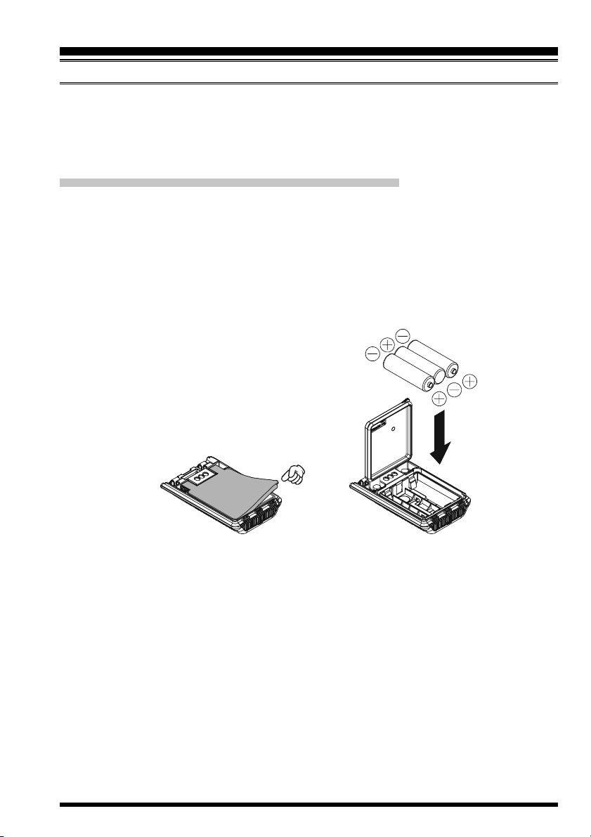
TO INSTALL ALKALINE BATTERIES INTO THE FBA-39
1. Lift up the lower right corner of the rubber cover, and then open the cover (Figure 1).
2. Referring to Figure 2, slide the batteries into the FBA-39 as shown in the illustration,
with the Negative
FBA-39.
3. Close the rubber cover.
4. Install the FBA-39 in the transceiver in the same manner as the FNB-101LI.
[–]
side of the batteries touching the spring connections inside the
Figure 1 Figure 2
The FBA-39 does not provide connections for charging, since Alkaline cells cannot be
re-charged. Therefore, the PA-44B/C may safely be connected to the EXT DC jack when
the FBA-39 is installed.
Notes:
The FBA-39 is designed for use only with AA-type Alkaline cells.
If you do not use the VX-8GE for a long time, remove the Alkaline batteries from the
FBA-39, as battery leakage could cause damage to the FBA-39 and/or the transceiver.
VX-8GE OPERATING MANUAL 11
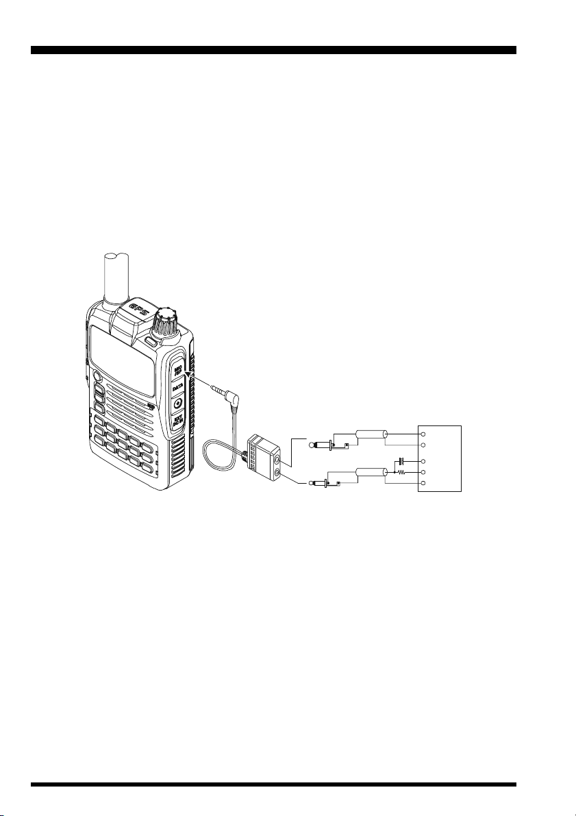
INTERFACE OF PACKET TNCS
The VX-8GE may be used for Packet operation, using the optional CT-44 Microphone
Adapter (available from your Yaesu dealer) for easy interconnection to commonly-available connectors wired to your TNC.
The audio level from the receiver to the TNC may be adjusted by rotating the DIAL knob
while pressing and holding the g key, as with voice operation. The input level to the
VX-8GE from the TNC should be adjusted at the TNC side; the optimum input voltage is
approximately 5 mV at 2000 Ohms.
Be sure to turn the transceiver and TNC off before connecting the cables, to prevent voltage spikes from damaging your transceiver.
MIC/SP Jack
CT-44 Microphone Adapter
TNC
10 Fµ
2 k
SP
GND
MIC
PTT
Ω
GND
EAR
MIC
VX-8GE OPERATING MANUAL12
OPERATION
Hi! I’m R. F. Radio, and I’ll be helping you along as you learn the many
features of the VX-8GE. I know you’re anxious to get on the air, but I en-
courage you to read the “Operation” section of this manual as thoroughly as
possible, so you’ll get the most out of this fantastic new transceiver. Now. . .let’s get
operating!
SWITCHING POWER ON AND OFF
1. Be sure the battery pack is installed, and that it is fully charged. Connect the antenna
to the top panel ANTENNA jack.
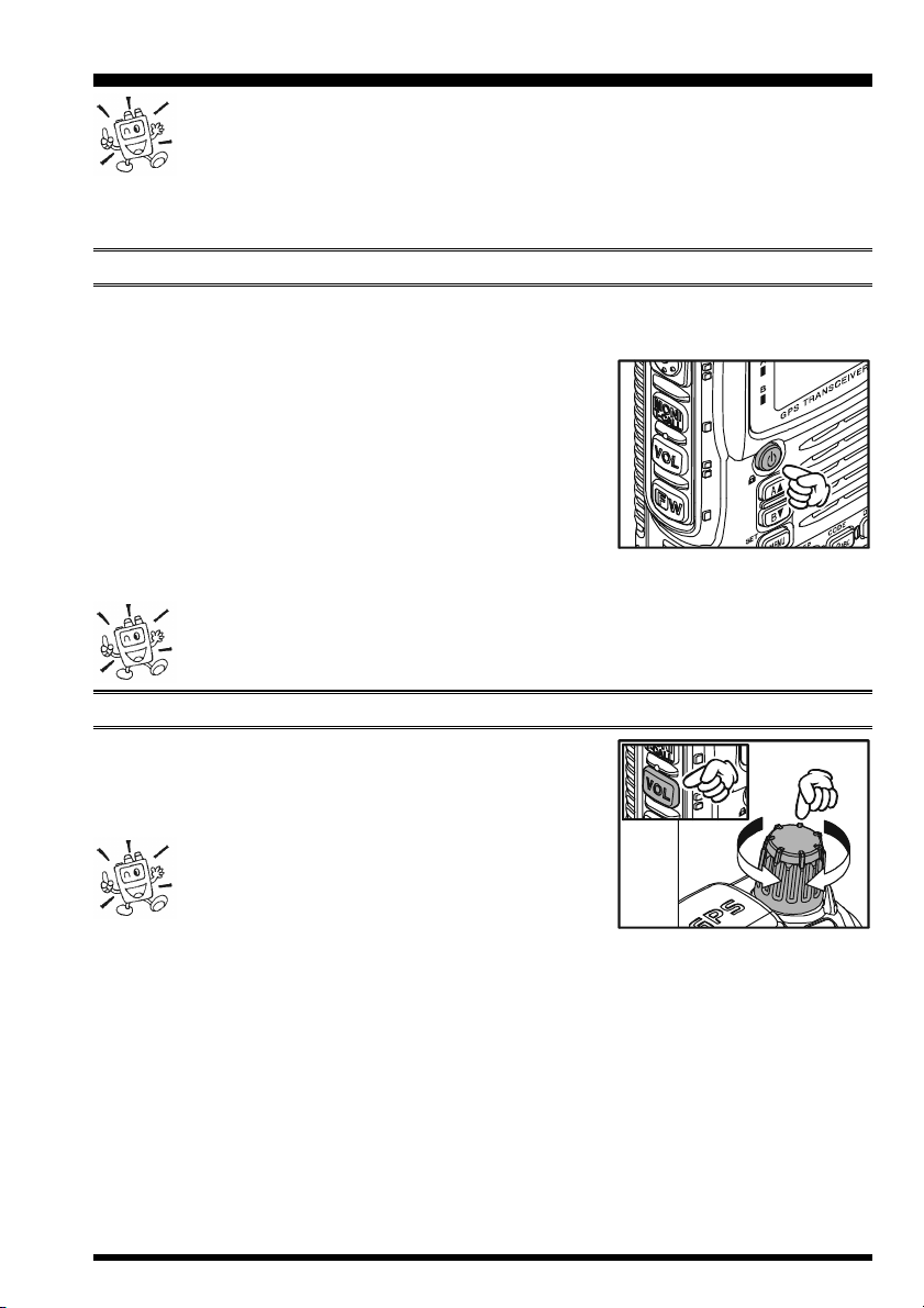
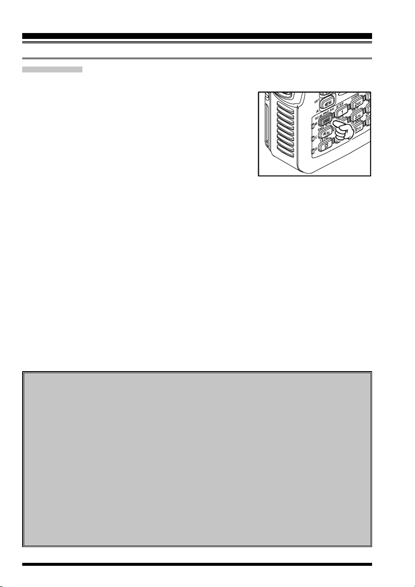
2. Press and hold in the p(PWR) switch (on the left side
of the front panel) for 2 seconds. Two beeps will be heard
when the switch has been held long enough. The opening message will appear briefly on the display, then the
frequency display will appear. After another two seconds, the receive-mode Battery Saver function will become active, unless you have disabled it (see page 112).
3. To turn the VX-8GE off, press and hold in the p(PWR) switch again for 2 seconds.
If you don’t hear the two “Beep” tones when the radio comes on, the Beeper
may have been disabled via the Menu system. See page 22, which tells you
how to reactivate the Beeper.
ADJUSTING THE VOLUME LEVEL
Rotate the DIAL knob while pressing and holding the g
key to set the desired audio level. Clockwise rotation increases the volume level.
1) The Volume level may be set on the
“A-Band” and “B-Band” separately.
2) While adjusting the Audio volume level, the
“SP VOLUME” notation appears in the S- & PO meter
area.
3) Pressing the f key followed by the g key, the DIAL knob function changes to the
Volume Level adjustment instead of the frequency control. In this case, the “Volume
Level Indicator” on the display blinks. Pressing the f key followed by the g key
again, returns the DIAL knob function to the frequency control. You may also change
the g key function via Set Mode Item 99: VOLUME MODE. See page 120 for details.
VX-8GE OPERATING MANUAL 13
OPERATION
SQUELCH ADJUSTMENT
The VX-8GE’s Squelch system allows you to mute the background noise when no signal
is being received. Not only does the Squelch system make “standby” operation more
pleasant, it also significantly reduces battery current consumption.
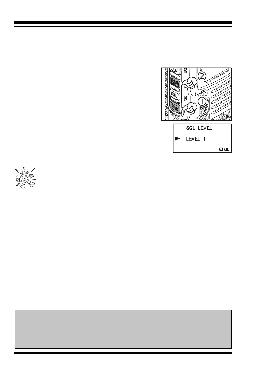
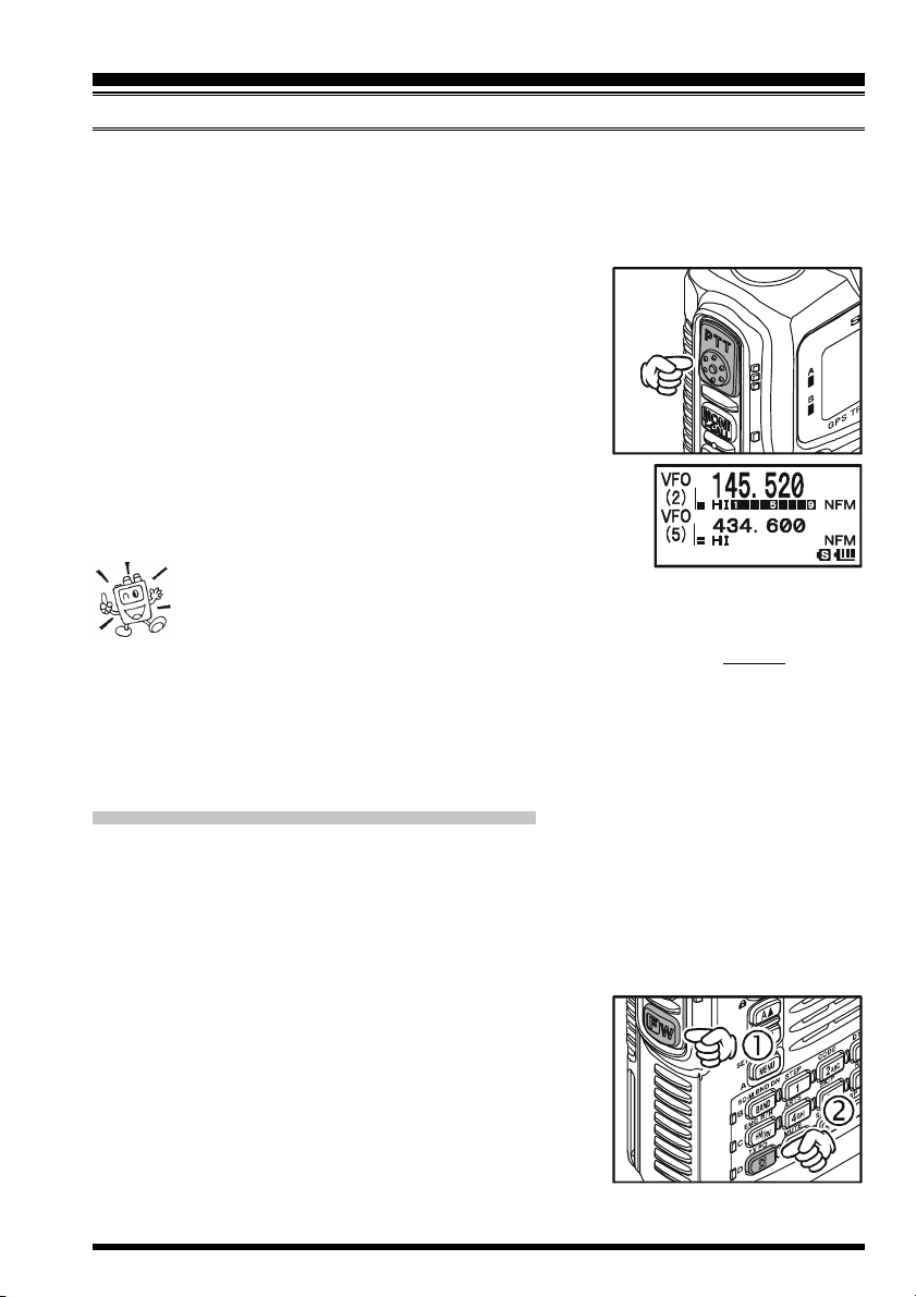
1. Press the f key, then press the e key on the left
side of the radio. This provides a “Short-cut” to Set
Mode Item 85: SQL LEVEL.
2. Now, rotate the DIAL knob to the point where the back-
ground noise is just silenced (typically at a setting of
about “3” or “4” on the scale); this is the point of maximum sensitivity to weak signals.
3. When you are satisfied with the Squelch threshold setting,
press the PTT key briefly to save the new setting and exit to
normal operation.
4. You may also adjust the Squelch setting by using the “Set”
(Menu) mode. See page 143 for details.
1) The Squelch level may be set on the “Main” and “Sub” bands separately.
2) If you’re operating in an area of high RF pollution, you may need to
consider “Tone Squelch” operation using the built-in CTCSS Decoder. This
feature will keep your radio quiet until a call is received from a station sending a carrier
which contains a matching (sub audible) CTCSS tone. Or if your friends have radios
equipped with DCS (Digital Coded Squelch) like your VX-8GE, try using that mode for
silent monitoring of busy channels.
24-HOUR CLOCK
The VX-8GE has a 24-hour clock with a calendar which covers all dates from
January 1, 2000 through December 31, 2099. Set the clock according to the “Clock
Set” column on page 107.
VX-8GE OPERATING MANUAL14
OPERATION
SELECTING THE OPERATING BAND
In the factory default configuration, the VX-8GE operates in the “Dual Receive” mode.
During Dual Receive operation, the “A-Band” frequency will be displayed on the upper
part of the LCD, and the “B-Band” frequency will be displayed on the lower part. The
“Operating” band (the band on which transmission and band/frequency changes are possible) is shown in large characters, and “Receive only” band is shown in small characters.
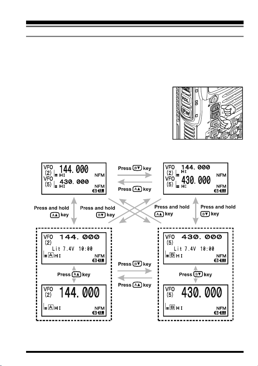
Press the a key briefly to engage the “A-Band” frequency as the “Operating” band. Alternatively, press the
b key briefly to engage the “B-Band” frequency, as described previously.
Press and hold in the a or b key for 1/2 seconds to
switch to Mono Band Operation. During Mono band operation, you may change the display between “double-size
character” and “large character” by pressing the a/b key.
VX-8GE OPERATING MANUAL 15
OPERATION
SELECTING THE FREQUENCY BAND
The VX-8GE covers an incredibly wide frequency range, over
which a number of different operating modes are used. Therefore, the VX-8GE’s frequency
coverage has been divided into
different operating bands. Each
band has its own preset channel
steps and operating modes. You can change the channel steps and operating modes later, if
you like (see page 24).
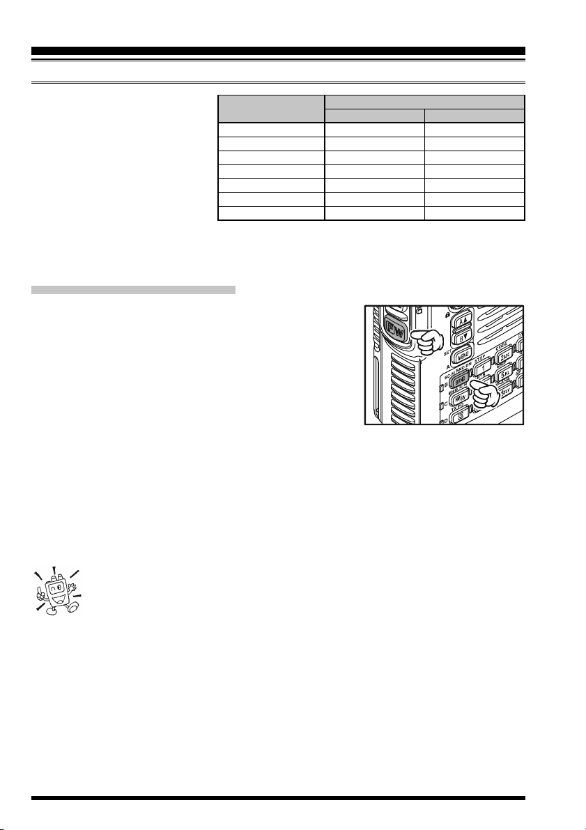
TO CHANGE OPERATING BANDS
1. Press the B key repeatedly. You will see the LCD
indication change to a higher frequency band each time
you press the B key. A Band Number according to
the receiving frequency is also displayed.
2. If you wish to move the operating band selection down-
ward (toward lower frequencies), press the f key
first, then press the B key.
3. The VX-8GE uses a dual VFO system (described previously). To switch TX/RX op-
eration from the “VFO-A” to the “VFO-B” instantly, press the b key briefly. Pressing
the a key will return TX/RX operation to “VFO-A”. The frequency band shown in
“Large” characters is the band on which transmission is possible; the band shown in
“Small” characters may only be used for reception.
4. Once you have selected the desired band, you may initiate manual tuning (or scan-
ning). See the discussions on the next page.
OPERATING BAND
[
BAND NUMBER
AIR Band
VHF HAM Band
VHF Band
INFO 1 Band
UHF HAM Band
UHF Band
INFO 2 Band
]
[1]
[2]
[3]
[4]
[5]
[6]
[7]
FREQUENCY RANGE
“VFO-A”
108-137 MHz
137-174 MHz
174-222 MHz
222-420 MHz
420-470 MHz
470-774 MHz
774-999.99 MHz
“VFO-B”
108-137 MHz
137-174 MHz
174-222 MHz
222-420 MHz
420-470 MHz
470-580 MHz
–
If desired, you may omit (skip) one or more bands from the band selection
loop for faster recall of your favorite operating bands. See page 119 for de-
tails.
VX-8GE OPERATING MANUAL16
OPERATION
FREQUENCY NAVIGATION
The VX-8GE will initially be operating in the “VFO” mode, as just described. This is a frequency step system which allows free tuning throughout the currently-selected operating band.
Three basic frequency navigation methods are available on the VX-8GE:
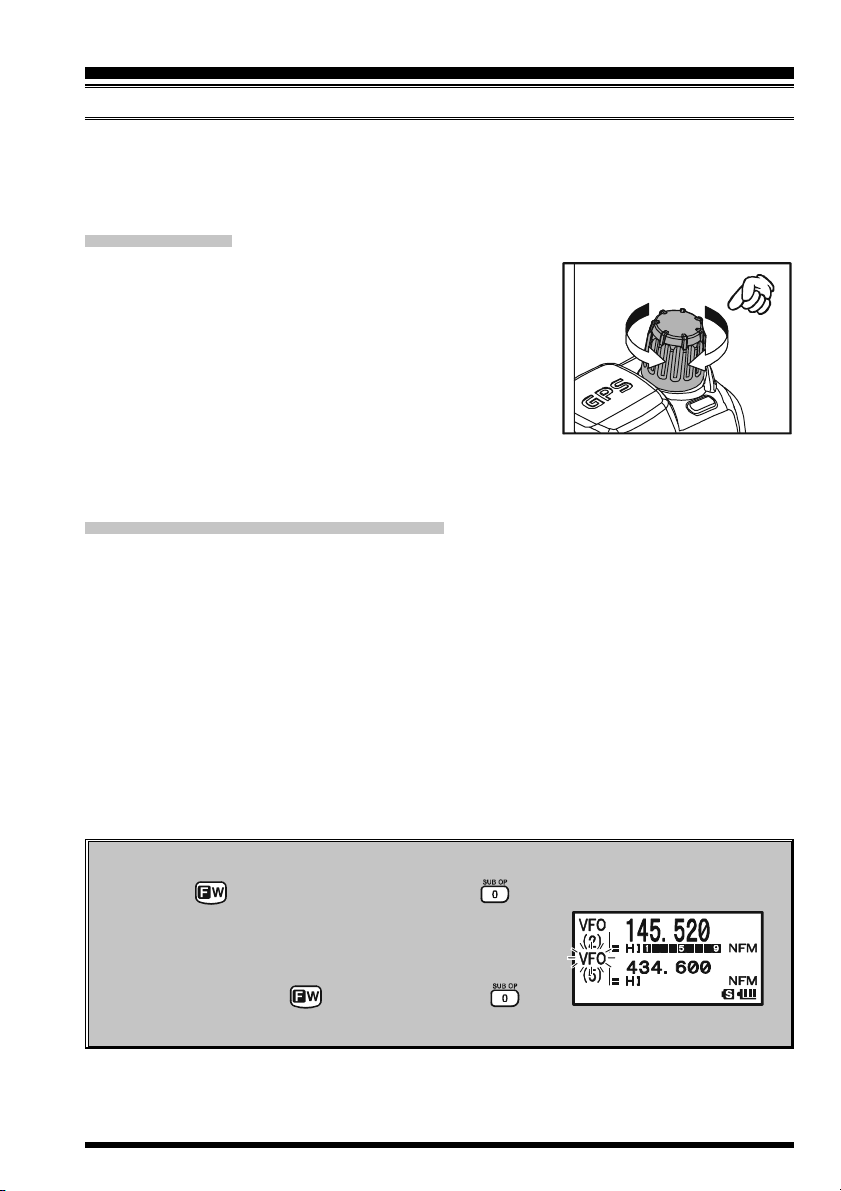
1) TUNING DIAL
Rotation of the DIAL knob allows tuning in the pre-pro-
grammed steps established for the current operating band.
Clockwise rotation of the DIAL knob causes the VX-8GE
to be tuned toward a higher frequency, while counter-clockwise rotation will lower the operating frequency.
If you press the f key briefly, then rotate the DIAL knob,
frequency steps of 1 MHz will be selected. This feature is
extremely useful for making rapid frequency excursions over the wide tuning range of the
VX-8GE.
2) DIRECT KEYPAD FREQUENCY ENTRY
The desired operating frequency may be entered directly from the keypad.
The operating mode will automatically be set once the new frequency is entered via the
keypad.
To enter a frequency from the keypad, just press the numbered digits on the keypad in the
proper sequence. There is no “Decimal point” key on the VX-8GE. However, there is a shortcut for frequencies ending in zero - press the c key after the last non-zero digit.
Examples:
To enter 145.520 MHz, press 145520
To enter 430.000MHz, press 43c
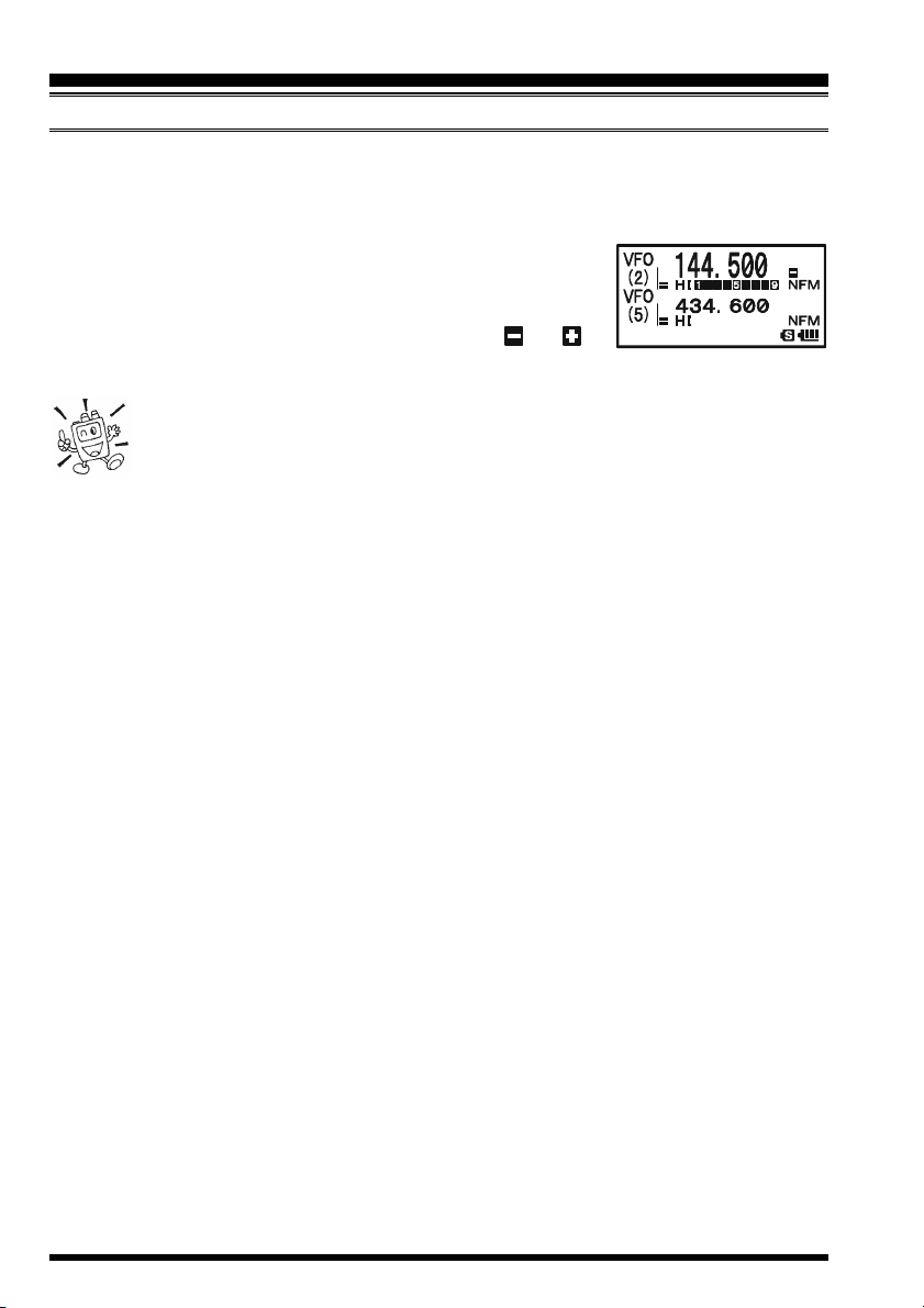
Sub Band Operation
When the key is pressed, followed by the key, the controls (except the TX
function) will act on the “Sub” band. When “Sub” Band
operation is activated, the “Sub” band “Frequency Control” icon will blink. After completing control of the
“Sub” band, press the key followed by the key
to return control to the “Main” band.
VX-8GE OPERATING MANUAL 17
OPERATION
FREQUENCY NAVIGATION
3) SCANNING
From the VFO mode, press and hold in the B key for one second, and while still
holding in the B key, rotate the DIAL knob to select
the bandwidth for the VFO scanner. Release the B key
to begin scanning toward a higher frequency. The scanner
will stop when it receives a signal strong enough to break
through the Squelch threshold. The VX-8GE will then hold
on that frequency according to the setting of the “RESUME”
mode (Menu Item 77: SCAN RESUME).
If you wish to reverse the direction of the scan (i.e. toward a lower frequency, instead of a
higher frequency), just rotate the DIAL knob one click in the counter-clockwise direction
while the VX-8GE is scanning. The scanning direction will be reversed. To revert to
scanning toward a higher frequency once more, rotate the DIAL knob one click clockwise.
Press the PTT switch briefly to cancel the scanning. See page 54 for more details regarding Scan Operation.
Dual Receive Notice
The VX-8GE may receive very strong signals on the Image frequency, and/or the
receiver sensitivity may be somewhat reduced by the combination of the “A-Band”
and “B-Band” frequencies while Dual Receive operation is engaged.
If you experience interference that you suspect may be coming in via an “Image”
path, you may calculate the possible frequencies using the formulas below. This
information may be used in the design of effective countermeasures such as traps,
etc.
16.369 MHz x n 11.7 MHz x n 9.8304 MHz x n
6.144 MHz x n 4.9152 MHz x n (n is an integer: 1, 2, 3, …)
“A-Band” Freq. = (“B-Band” Freq. ± 46.35 MHz) x
“B-Band” Freq. = (“A-Band” Freq. ± 47.25 MHz) x n (@ “A-Band” = NFM)
n
VX-8GE OPERATING MANUAL18
OPERATION
TRANSMISSION
Once you have set up an appropriate frequency inside one of the dual amateur bands on
which the VX-8GE can transmit (144 MHz or 430 MHz), you’re ready to transmit. These
are the most basic steps; more advanced aspects of transmitter operation will be discussed
later.
1. To transmit, press the PTT switch, and speak into the
front panel microphone (located in the upper right-hand
corner of the speaker grille) in a normal voice level.
The LED of the “A” or “B” which is designated the
“Main” band will glow red during transmission.
2. To return to the receive mode, release the PTT switch.
3. During transmission, the relative power level will be
indicated on the LCD. Additionally, the “L1”, “L2”, “L3”,
or “HI” icon will appear at the left side of the PO meter,
corresponding with the “Power” Level setting.
1) If you’re just talking to friends in the immediate
area, you’ll get much longer battery life by switching to Low Power operation. To do this, press the f key, then press the d key so that the “Low
Power” icon appears at the bottom of the display. And don’t forget: always have an
antenna connected when you transmit.
2) Transmission is not possible on the “Sub” band, nor on any frequencies other than
the 144 MHz and 430 MHz bands on the “Main” band.
3) Never transmit without having an antenna connected.
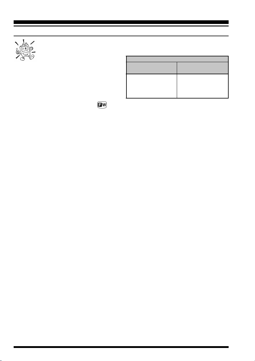
CHANGING THE TRANSMITTER POWER LEVEL
You can select between a total of four transmitter power levels on your VX-8GE. The
exact power output will vary somewhat, depending on the voltage supplied to the transceiver. With the standard FNB-101LI Battery Pack and external DC source, the power
output levels available are: “L1”, “L2”, “L3”, or “HI”
To change the power level:
1. The default setting for the power output is “High;” in
this configuration, the display shows the “HI” icon.
Pressing the f key, followed by the d key, causes
the power level “L1”, “L2”, or “L3” to appear.
2. Press the f key, followed by the d key (repeat-
edly, if necessary) to make the “HI” icon appear and
restore “High Power” operation.
VX-8GE OPERATING MANUAL 19
OPERATION
TRANSMISSION
1) The VX-8GE is smart! You can set up Low power on one band (like UHF),
while leaving VHF on High power, and the radio will remember the different
settings on each band. And when
you store memories, you can store High and
Low power settings separately in each
memory, so you don’t waste battery power
when using very close-in repeaters!
2) When you are operating on one of the Low
FNB-101LI/-102LI
or EXT DC (7.4 V
HI: 5.0 W,
L3: 2.5 W,
L2: 1.0 W,
L1: 0.05 W
power settings, you can press the key, then press the PTT switch, to cause the VX8GE to transmit (temporarily) on High power. After one transmission, the power level
will revert to the previously-selected Low power setting.
TRANSMIT POWER
)
(
w/Fresh Batteries
FBA-39
L2: 1.0 W,
L1: 0.05 W
)
VX-8GE OPERATING MANUAL20
ADVANCED OPERATION
Now that you mastered the basics of VX-8GE operation, let’s learn more about some of
the really neat features.
KEYBOARD LOCKING
In order to prevent accidental frequency change or inadvertent transmission, various keys
and switches may be locked out. The possible lockout combinations are:
KEY: Just the front panel keys are locked out
DIAL: Just the top panel DIAL knob is locked out
KEY&DIAL: Both the DIAL knob and Keys are locked out
PTT: The PTT switch is locked (TX not possible)
KEY&PTT: Both the keys and PTT switch are locked out
DIAL&PTT: Both the DIAL knob and PTT switch are locked out
ALL: All of the above are locked out
To lock out some or all of the keys:
1. Press and hold the m key for one second to enter the Set Mode.
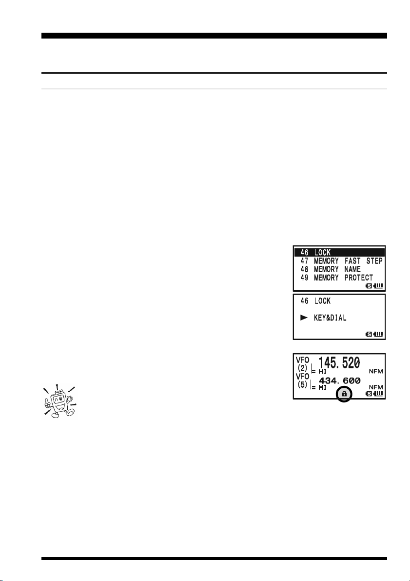
2. Rotate the DIAL knob to select Set Mode Item 46: LOCK.
3. Press the m key briefly to enable selection of this Menu
Item.
4. Rotate the DIAL knob to choose between one of the lock-
ing schemes as outlined above.
5. When you have made your selection, press the PTT switch
to save the new setting and resume normal operation.
To activate the locking feature:
(
Press the
on the LCD. To cancel locking, press the
p
PWR) switch briefly. The “k” icon will appear
(
p
PWR) switch again.
Even when “ALL” keys have been locked out, one
(
key actually is not locked out: the
remains available so you can unlock your keypad when you want to!
p
PWR) switch
VX-8GE OPERATING MANUAL 21
ADVANCED OPERATION
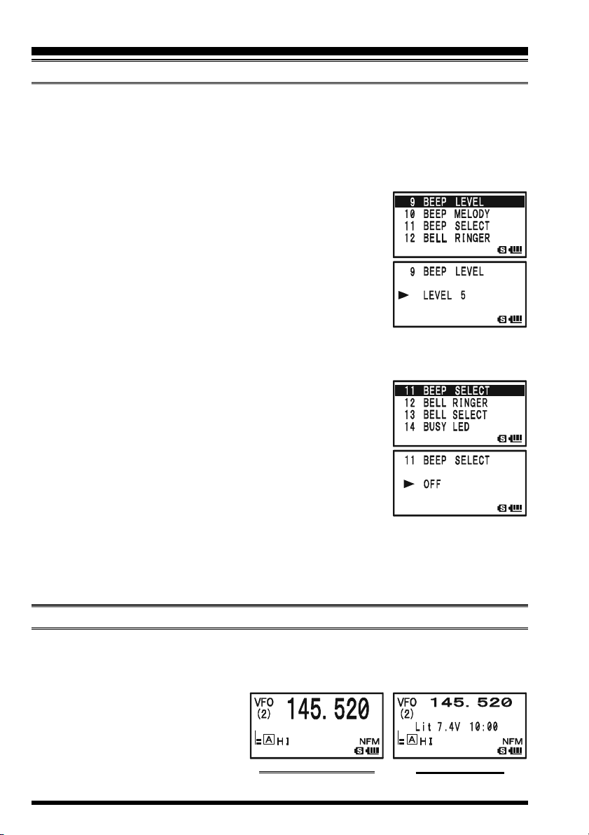
ADJUSTING THE KEYPAD BEEPER VOLUME LEVEL
A keypad beeper provides useful audible feed back whenever a key button is pressed. The
keypad beeper level changes according to the receiver audio volume level setting. However, you may adjust the volume balance between the receiving audio and keypad beeper
using Set Mode Item 9: BEEP LEVEL.
1. Press and hold the m key for one second to enter the Set Mode.
2. Rotate the DIAL knob to select Set Mode Item 9: BEEP
LEVEL.
3. Press the m key briefly to enable selection of this Set
Mode Item.
4. Rotate the DIAL knob to select the desired level.
5. When you have made your choice, press the PTT switch to
save the new setting and return to normal operation.
Additionally, if you want to turn the beep off:
1. Press and hold the m key for one second to enter the Set Mode.
2. Rotate the DIAL knob to select Set Mode Item 11: BEEP
SELECT.
3. Press the m key briefly to enable selection of this Set
Mode Item.
4. Rotate the DIAL knob to change the setting to “OFF”.
5. When you have made your choice, press the PTT switch to
save the new setting and return to normal operation.
6. If you wish to re-enable the Beeper, just repeat the above
procedure, rotating the DIAL knob to select “KEY” or “KEY & SCAN” in step “4”
above.
KEY: The beeper sounds when you press any key.
KEY & SCAN: The beeper sounds when you press a key or when the scanner stops.
SETTING THE FREQUENCY DISPLAY IMAGE SIZE
When operating in “Mono” band, pressing the a or b key, causes the LCD to “toggle”
between display of double-size characters and large characters. However, this feature
does not work during Dual Receive operation, as both the “Main” band and “Sub” band
frequencies are shown on the display.
DOUBLE-SIZE CHARACTERS
VX-8GE OPERATING MANUAL22
LARGE CHARACTERS
ADVANCED OPERATION
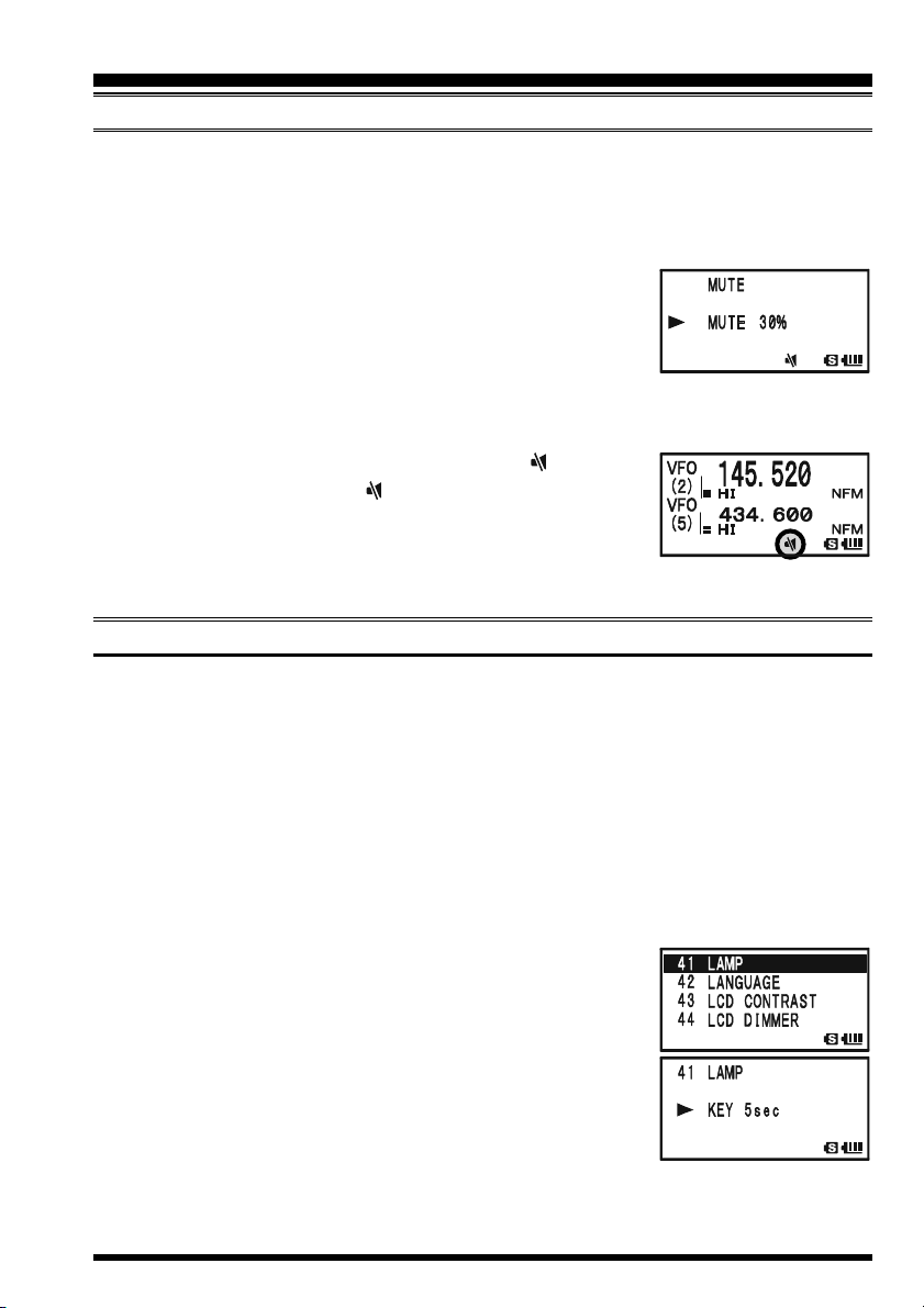
AUDIO MUTING
The Audio Mute feature is useful in situations where it would be helpful to reduce the
audio level of the “Receive Only” band (Small character display) whenever you receive a
signal on the “Main” band (Large character display) during Dual Receive operation.
To activate the Audio Mute feature:
1. Press the f key, then press the 7 key. This provides a
“Short-cut” to Set Mode Item 57: MUTE.
2. Rotate the DIAL knob to select the desired muting level
(MUTE 30%, MUTE 50%, MUTE 100%, or OFF).
3. When you have made your choice, press the PTT switch to save the new setting and
return to normal operation.
When the Audio Mute feature is activated, the “ ” icon will
appear on the display, and the “ ” icon blinks while muting the
“Receive Only” band audio.
To cancel the Audio Mute feature, just repeat the above procedures, selecting “OFF” in step 2 above.
KEYPAD/LCD ILLUMINATION
Your VX-8GE includes a reddish illumination lamp which aids in nighttime operation.
The red illumination yields clear viewing of the display in a dark environment, with minimal degradation of your night vision. Three options for activating the lamp are provided:
KEY 2sec - KEY 10sec: Illuminates the Keypad/LCD for the selected illumination
time when any key is pressed.
CONTINUOUS: Illuminates the Keypad/LCD continuously.
OFF: Disables the Keypad/LCD lamp.
Here is the procedure for setting up the Lamp mode:
1. Press and hold the m key for one second to enter the Set Mode.
2. Rotate the DIAL knob to select Set Mode Item 41: LAMP.
3. Press the m key briefly to enable selection of this Set
Mode Item.
4. Rotate the DIAL knob to select one of the three modes de-
scribed above.
5. When you have made your choice, press the PTT switch to
save the new setting and return to normal operation.
VX-8GE OPERATING MANUAL 23
ADVANCED OPERATION
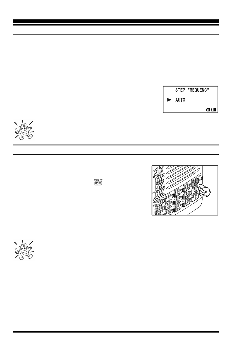
CHANGING THE CHANNEL STEPS
The VX-8GE’s frequency synthesizer provides the option of utilizing tuning steps of 5,
6.25, 8.33, 10, 12.5, 15, 20, 25, 50 and 100 kHz per step. The VX-8GE is set up at the
factory with different default steps for each operating band which are probably satisfactory
for most operation. However, if you need to change the channel step increments, the procedure to do so is very easy.
1. Press the f key, then press the 1 key on the left side of the radio. This provides a
“Short-cut” to Set Mode Item 89: STEP FREQUENCY.
2. Rotate the DIAL knob to select the desired step size.
3. Press the PTT switch to save the new setting and return to
normal operation.
1) 8.33 kHz steps are available only when receiving on the Air band.
2) 5 kHz steps are not available for use on 250 - 300 MHz, nor above 580
MHz.
CHANGING THE RECEIVING MODE
The VX-8GE provides for automatic mode changing when the radio is tuned to different
operating frequencies. However, should an unusual receiving situation arise in which you need to change to a different receiving mode, just press the key. The receiving
modes available are:
AUTO: The receive mode is automatically set accord-
ing to the default values for the selected frequency range
NFM: Frequency Modulation
AM: Amplitude Modulation
Unless you have a compelling reason to do so, leave the Automatic Mode
Selection feature on in order to save time and trouble when changing bands.
If you make a mode change for a particular frequency or station, you can
always store that one channel into memory, as the mode setting will be memorized along
with the frequency information.
VX-8GE OPERATING MANUAL24

ADVANCED OPERATION
SQL S-METER
A special SQL (Squelch) S-meter feature is provided on this radio. This feature allows
you to set the squelch so only signals exceeding a certain S-meter level will open the
squelch.
To set up the S-meter squelch feature for operation, use the following procedure:
1. Press and hold the m key for one second to enter the Set Mode.
2. Rotate the DIAL knob to select Set Mode Item 86: SQL S-
METER.
3. Press the m key briefly to enable selection of this Set
Mode Item.
4. Rotate the DIAL knob to select the desired signal strength
level for the squelch threshold (LEVEL1 - LEVEL9 or OFF).
5. When you have made your choice, press the PTT switch to
save the new setting and return to normal operation.
1) When the SQL S-meter is activated, the S-meter segment corresponding to
the squelch threshold which was set by step 4 above will blink.
2) The receiver’s squelch will open based on the higher of the levels set by the
Noise Squelch or the S-meter Squelch system.
For example:
a) If the Noise Squelch (SQL control) is set so that signals at a level of “S-3” will open
the squelch, but the SQL S-meter (Set Mode Item 93) is set to “LEVEL 5,” the squelch
will only open on signals which are “S5” or stronger on the S-meter.
b) If the SQL S-meter is set to “S3,” but the Noise Squelch is set to a high level which
will only pass signals which are Full Scale on the S-meter, the squelch will only open on
signals which are Full Scale on the S-meter. In this case, the Noise Squelch overrides
the action of the S-meter Squelch.
VX-8GE OPERATING MANUAL 25

REPEATER OPERATION
GENERAL
Repeater stations, usually located on mountaintops or other high locations, provide a dramatic extension of the communication range for low-powered hand-held or mobile transceivers. The VX-8GE includes a number of features, which make repeater operation simple
and enjoyable.
REPEATER SHIFTS
Your VX-8GE has been configured, at the factory, for the repeater shifts customary in
your country. For the 144 MHz band, this usually will be 600 kHz, while the 430 MHz
shift will be 1.6 MHz or 7.6 MHz.
Depending on the part of the band in which you are operating, the repeater shift may be
either downward ( ) or upward ( ),
and one of these icons will appear to
the right of the display frequency on
the LCD when repeater shifts have
been enabled.
AUTOMATIC REPEATER SHIFT (ARS
)
The VX-8GE provides a convenient Automatic Repeater Shift feature, which causes the
appropriate repeater shift to be automatically applied whenever you tune into the designated repeater sub-bands in your country. These sub-bands are shown below.
If the ARS feature does not appear to be working, you may have accidentally disabled it.
To re-enable ARS:
1. Press and hold the m key for one second to enter the Set Mode.
2. Rotate the DIAL knob to select Set Mode Item 69: RPT ARS.
3. Press the m key briefly to enable selection of this Set
Mode Item.
4. Rotate the DIAL knob to select “ON”(to enable Automatic
Repeater Shift).
5. When you have made your choice, press the PTT switch to
save the new setting and return to normal operation.
ARS-Repeater Subbands
145.6 145.8
2-m
433.00 434.60433.40 435.00
70-cm
439.45438.20
Euro Version 1
Euro Version 2
VX-8GE OPERATING MANUAL26
REPEATER OPERATION
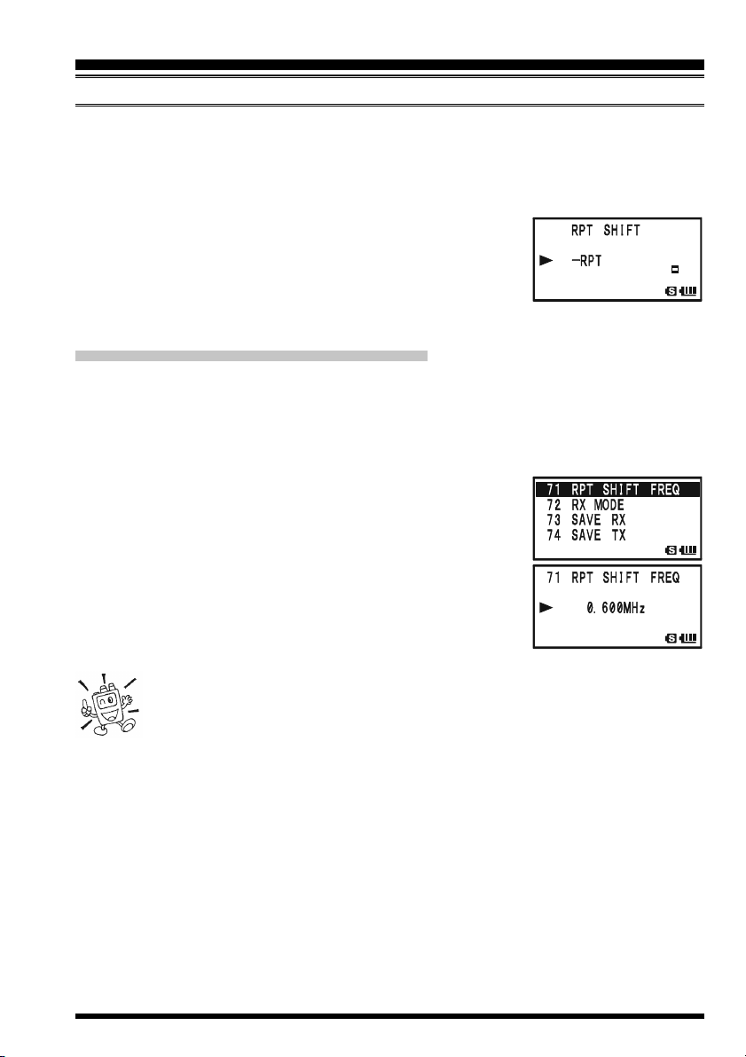
MANUAL REPEATER SHIFT ACTIVATION
If the ARS feature has been disabled, or if you need to set a repeater shift direction other
than that established by the ARS, you may set the direction of the repeater shift manually.
To do this:
1. Press the f key, then press the 6 key. This provides a “Short-cut” to Set Mode
Item 70: RPT SHIFT.
2. Rotate the DIAL knob to select the desired shift among
“–RPT,” “+RPT,” and “SIMPLEX.”
3. Press the PTT switch to save the new setting and exit to
normal operation.
CHANGING THE DEFAULT REPEATER SHIFTS
If you travel to a different region, you may need to change the default repeater shift, to
ensure compatibility with local operating requirements.
To do this, follow the procedure below:
1. Press and hold the m key for one second to enter the Set Mode.
2. Rotate the DIAL knob to select Set Mode Item 71: RPT
SHIFT FREQ.
3. Press the m key briefly to enable selection of this Set
Mode Item.
4. Rotate the DIAL knob to select the new repeater shift mag-
nitude.
5. Press the PTT switch to save the new setting and return to
normal operation.
If you just have one “odd” split that you need to program, don’t change the
default repeater shift! Enter the transmit and receive frequencies separately,
as shown on page 44.
VX-8GE OPERATING MANUAL 27
REPEATER OPERATION
CHECKING THE REPEATER UPLINK (INPUT) FREQUENCY
It often is helpful to be able to check the uplink (input) frequency of a repeater, to see if the
calling station is within direct (“Simplex”) range.
To do this, just press the h key. You’ll notice that the display has shifted to the repeater
uplink frequency. Press the h key again to cause operation to
return to normal monitoring of the repeater downlink (output)
frequency. While you are listening on the input frequency of the
repeater using the h key, the repeater offset icon (“ ” or ”)
will blink.
The configuration of h key may be set either to “RV” (for checking the
input frequency of a repeater, or “HM” (for instant switching to the “Home”
channel for the band you are operating on). To change the configuration of
h key, use Set Mode Item 34: HOME/REVERSE. See page 135.
VX-8GE OPERATING MANUAL28
 Loading...