


VHF/UHF
ULTRA-COMPACT DUAL-BAND TRANSCEIVER
WITH WIDE BAND COVERAGE
VX-3R/E
OPERATING MANUAL
YAESU MUSEN CO., LTD.
Tennozu Parkside Building
2-5-8 Higashi-Shinagawa, Shinagawa-ku, Tokyo 140-0002 Japan
YAESU USA
6125 Phyllis Drive, Cypress, CA 90630, U.S.A.
YAESU UK
Unit 12, Sun Valley Business Park, Winnall Close
Winchester, Hampshire, SO23 0LB, U.K.

Contents
General Description ................................................................... 1
Controls & Connections ............................................................ 2
Keypad Functions ................................................................... 3
LCD Display ........................................................................... 4
Accessories & Options ............................................................... 5
Installation of Accessories ......................................................... 6
Antenna Installation ................................................................ 6
Installation of FNB-82LI Battery Pack .................................. 6
Battery Charging ..................................................................... 7
Installation of FBA-37 Alkaline Battery Case ....................... 8
Battery Life Information ......................................................... 8
Interface of Packet TNCs .......................................................... 9
Operation .................................................................................. 10
Switching Power On and Off ............................................... 10
Adjusting the Volume Level ................................................ 10
Squelch Adjustment .............................................................. 11
Selecting the Operating Band ............................................... 12
Frequency Navigation .......................................................... 13
Transmission ......................................................................... 14
AM and FM Broadcast Reception ....................................... 15
SUB-RX Operation ......................................................... 16
Advanced Operation ................................................................ 18
Keyboard Locking ................................................................ 18
Adjusting the Keypad Beeper Volume Level ...................... 19
Keypad/LCD Illumination .................................................... 20
Checking the Battery Voltage .............................................. 20
Changing the Channel Steps ................................................. 21
Changing the Receiving Mode ............................................. 21
S-meter Squelch .................................................................... 22
Checking the Temperature ................................................... 23
Repeater Operation ................................................................. 24
Repeater Shifts ...................................................................... 24
Automatic Repeater Shift (ARS) .......................................... 24
Manual Repeater Shift Activation ........................................ 25
Changing the Default Repeater Shifts ............................ 25
Tone Calling (1750 Hz) ........................................................ 26
Checking the Repeater Uplink (Input) Frequency ............... 26
CTCSS/DCS/EPCS Operation ............................................... 28
CTCSS Operation ................................................................. 28
DCS Operation ..................................................................... 30
DCS Code Inversion ........................................................ 31
Tone Search Scanning .......................................................... 32
EPCS (Enhanced Paging & Code Squelch) ......................... 34
Storing the CTCSS Tone Pairs for EPCS Operation ...... 34
Activating the Enhanced Paging &
Code Squelch System ...................................................... 35
Paging Answer Back ....................................................... 36
CTCSS/DCS/EPCS Bell Operation ...................................... 37
Programming the User Beep ........................................... 38
Split Tone Operation ............................................................ 39
Memory Mode .......................................................................... 41
Regular Memory Channel Operation ................................... 42
Memory Storage .............................................................. 42
Storing Independent Transmit Frequencies
(“Odd Split”) .............................................................. 43
Memory Recall ................................................................ 43
HOME Channel Memory ................................................ 44
Home Channel Recall ................................................ 44
Home Channel Frequency Change ............................ 44
Labeling Memories .......................................................... 45
Memory Offset Tuning ................................................... 46
Masking Memories .......................................................... 47
Memory Bank Operation ................................................. 48
Assigning Memories to a Memory Bank ................... 48
Memory Bank Recall ................................................. 48
Removing Memories from a Memory Bank .............. 49
Changing a Memory Bank’s Name ........................... 49
Moving Memory Data to the VFO ................................. 50
Memory Only Mode ........................................................ 50
Special Memory Channel Operation .................................... 51
Weather Broadcast Channels .......................................... 51
VHF Marine Channels .................................................... 52
Short-wave Broadcast Station Memory Channels .......... 53
Scanning .................................................................................... 54
Setting the Scan-Resume Mode ........................................... 54
VFO Scanning ...................................................................... 56
How to Skip (Omit) a Frequency
during VFO Scan ............................................................. 57
Setting the Squelch Level
during active Scanning Operation ................................... 57
Memory Scanning ................................................................. 58
How to Skip (Omit) a Channel
during Memory Scan Operation ...................................... 59
Preferential Memory Scan .............................................. 60
Memory Bank Scan ......................................................... 61
Programmable (Band Limit) Memory Scan (PMS) ............. 62
Priority Channel Scanning (Dual Watch) ............................ 63
Priority Revert Mode ....................................................... 64
Automatic Lamp Illumination on Scan Stop ........................ 65
Band Edge Beeper ................................................................ 65
Smart Search Operation .......................................................... 66
Setting the Smart Search Mode ............................................ 66
Storing Smart Search Memories ........................................... 67
Channel Counter Operation ................................................... 68
Setting the Channel Counter Sweep Width ......................... 69
Message Feature ....................................................................... 70
Programming a Message ....................................................... 70
Programming a Member List ................................................ 71
Set Your Personal ID ............................................................ 72
Sending a Messages .............................................................. 72
Receiving a Message ............................................................ 73
Emergency Feature .................................................................. 74
Emergency Channel Operation ............................................ 74
Emergency Automatic ID (EAI) Feature ............................. 75
Selecting the EAI mode and its Transmit Time .............. 76
Activating the EAI feature .............................................. 76
To Locate an Unresponsive Operator
Using the EAI feature ...................................................... 77
TM
(Automatic Range Transponder System) ............... 78
ARTS
Basic ARTS Setup and Operation ........................................ 79
ARTS Polling Time Options ................................................ 79
ARTS Alert Beep Options .................................................... 80
CW Identifier Setup .............................................................. 81
Internet Connection Feature ................................................... 82
SRG (“Sister Radio Group”) mode ...................................... 82
FRG (“Friendly Radio Group”) mode ................................. 83
Programming the FRG code ............................................ 83
Operation (Accessing an FRG Node) ............................. 84
DTMF Operation ..................................................................... 85
Manual DTMF Tone Generation ......................................... 85
DTMF Autodialer ................................................................. 85
CW Learning Feature ............................................................. 88
CW Training Feature .............................................................. 90
Miscellaneous Setting ............................................................... 91
Password ............................................................................... 91
Programming the
Assign the Set Mode Item to the
ATT (Front End Attenuator) ................................................ 93
Receive Battery Saver Setup ................................................ 93
Wakeup Feature .................................................................... 94
TX Battery Saver .................................................................. 95
Disabling the BUSY Indicator ............................................. 95
Automatic Power-Off (APO) Feature .................................. 96
Transmitter Time-Out Timer (TOT) .................................... 97
Automatic Power-On Feature ............................................... 98
Busy Channel Lock-Out (BCLO) ........................................ 98
Changing the TX Deviation Level ....................................... 99
Changing the Microphone Gain ........................................... 99
My Bands Operation .......................................................... 100
Changing the Status of the [VOL] Key .............................. 101
Cloning .................................................................................... 102
Set (Menu) Mode .................................................................... 103
Reset Procedures .................................................................... 125
Specifications .......................................................................... 126
FCC Notice ............................................................................. 128
]
[
Key .................................................. 92
[ ]
Key ..................... 92

GENERAL DESCRIPTION
The VX-3R/E is a micro-miniature multiband FM transceiver with extensive receive fre-
quency coverage, providing local-area two-way amateur communications along with un-
matched monitoring capability.
The VX-3R/E’s incredibly small size allows you to take it anywhere - hiking, skiing, or
while walking around town - and its operating flexibility brings the user many avenues of
operating enjoyment. Its incredibly tiny FNB-82LI Lithium-Ion Battery Pack provides up
to 1.5 Watts of transmit power on VHF, and 1 Watt on UHF. In addition to the 144- and
430-MHz transceiver operation, the VX-3R/E provides receive coverage of the AM (MF)
broadcast band, with the internal bar antenna, the FM broadcast bands, HF Shortwave
Bands, VHF and UHF TV bands, the VHF AM aircraft band, and a wide range of commer-
cial and public safety frequencies! The VX-3R/E internal antenna bar provides good AM
broadcast receive capabilities without having to use an external antenna.
Additional features include an Enhanced Paging and Code Squelch (EPCS), which allows
you to page a particular station and only receive calls from that station. A security Pass-
word may be set, which will allow you to turn on and operate your transceiver only after
you enter your Password. A convenient key provides access to Vertex Standard’s WIRES™
(Wide-Coverage Internet Repeater Enhancement System). The Emergency Automatic ID
(EAI) function can automatically cause your VX-3R/E to transmit your callsign and en-
gage your rig’s microphone, even if you are disabled and unable to press the PTT switch.
Features include: transmit Time-Out Timer (TOT), Automatic Power-Off (APO), and Au-
tomatic Repeater Shift (ARS). Yaesu’s exclusive ARTS™ (Auto-Range Transponder Sys-
tem) which “beeps” the user when you move out of communications range with another
ARTS™ equipped station. There is provision to reduce the TX deviation for use in areas of
high channel congestion. The squelch circuit allows adjusting the squelch to open at a
programmable setting of the S-Meter, thus reducing guesswork in setting the squelch thresh-
old.
We appreciate your purchase of the VX-3R/E, and encourage you to read this manual
thoroughly, and learn about the many exciting features of your thrilling new Yaesu hand-
held transceiver!
VX-3R/E OPERATING MANUAL 1

CONTROL & CONNECTIONS
ANTENNA Jack
Connect the supplied rub-
ber flex antenna (or an-
other antenna presenting
a 50-Ohm impedance)
here.
PTT Switch
Press this switch to trans-
mit, and release it to re-
ceive, after your trans-
mission is completed.
MIC/SP Jack
This four-conductor min-
iature jack provides con-
nection points for micro-
phone audio, earphone
audio, PTT, and ground.
DIAL Knob
The main tuning Dial is used for set-
ting the operating frequency, and is
used for audio volume level, menu se-
lections, and other adjustments.
To rotate this Dial knob, pull the knob
to unlock the mechanical dial lock, and
then rotate the Dial knob.
TX/BUSY Indicator
This indicator glows
green when the squelch
opens, and turns red dur-
ing transmit. During
“Emergency” operation
(see page 74), this indi-
cator will glow (or flash)
white.
MONI/T.CALL Switch
USA/EXP version:
Pressing this key dis-
ables the noise squelch-
ing action, allowing you to
hear very weak signals
near the background
noise level.
Europe version:
Pressing this key acti-
vates the T-CALL (1750
Hz) for repeater access.
POWER Switch
Press and hold this
switch in for one second
to toggle the transceiver’s
power on and off.
KEYPAD
These nine keys select
many of most important
operating features on the
VX-3E. The functions of
the keys are described in
detail on the pages to fol-
low.
MIC
The internal micro-
phone is located
here.
EAR Jack
This 3-pin miniature jack
provides connection
points for stereo ear-
phones.
This 3-pin miniature jack
allows connection to ste-
reo earphones. When
using after-market stereo
earphones with this jack,
you may enjoy the FM
broadcast band in stereo.
EXT DC Jack
This coaxial DC jack al-
lows connection to an
external DC power
source (3.7 - 7.0V DC).
The center pin of this jack
is the Positive (+) connec-
tion.
SPEAKER
The internal speaker
is located here.
VX-3R/E OPERATING MANUAL2

KEY
PRIMARY FUNCTION
(
PRESS KEY
Switches the operating
mode.
Moves operation to the
next-highest frequency
band. Activates the
“Memory Bank” feature
while in the Memory Re-
call mode.
Switches the transmit
power output between “HI”
and “LOW”.
Switches frequency con-
trol between the VFO and
Memory Systems.
Activates the “Alternate”
key function.
Reverses transmit and re-
ceive frequencies while
working through a re-
peater.
Activates the WIRES™
(Internet Connection) fea-
ture.
Enter the Broadcast Re-
ception mode.
While in the Broadcast Re-
ception mode, press the
[
BAND] key to toggle the
receiving band between
“AM” broadcast band and
“FM” broadcast band.
N.A.
)
CONTROL & CONNECTIONS
KEYPAD FUNCTIONS
SECONDARY FUNCTION
(
[
PRESS
F/W] + KEY
Activates CTCSS or DCS
operation.
Moves operation to the
next-lowest frequency
band. Holding this key af-
ter pressing the [F/W] key
activate the key lockout
feature.
Selects the synthesizer
steps to be used during
VFO operation.
Activates the “Memory
Tune” function while in the
Memory Recall mode.
Disables the “Alternate”
key function.
Switches operation to the
“Home” (favorite fre-
quency) channel.
Recalls the “Weather
Broadcast” channels and
Short-wave broadcast sta-
tion channels.
Enables the antenna se-
lection to be used.
Toggle the DIAL knob
function between the “Fre-
quency Control” and “Re-
ceiver Audio Control”.
)
THIRD FUNCTION
(
PRESS AND HOLD KEY
Activates the Smart
Search™ and Channel
Counter features.
Activates the Scanner Up-
ward (toward a higher fre-
quency or a higher chan-
nel number).
Enters the Set (Menu)
Mode.
Activates the Dual Watch
feature.
Activates the “Memory
Write” mode (for memory
channel storage).
Activates the Emergency
Channel Operation. See
page 74.
Activates the ARTS™ fea-
ture.
Activates the SUB-RX
Operation. See page 16.
Rotate the DIAL knob
while holding the [VOL
key to adjust the audio vol-
ume level.
)
]
VX-3R/E OPERATING MANUAL 3

CONTROL & CONNECTIONS
LCD DISPLAY
Memory Bank Active
Skip Memory Channel or
Preferential Memory Channel
Priority Channel
Audio Volume Level
Secondary Keypad Active
Dual Watch Active
Low TX Power Selected
Operating Band Number or Memory Channel Number
Repeater Shift Direction
CTCSS/DSC Operation
Internet Connection
Feature Active
Operating Frequency
Battery Indicator
Bell Alarm Active
Key Lock Active
Battery Saver Active
Operating Mode
Automatic Power-Off Active
S- & PO MeterStereo Audio
VX-3R/E OPERATING MANUAL4

ACCESSORIES & OPTIONS
SUPPLIED ACCESSORIES
FNB-82LI 3.7 V, 1100 mAh Rechargeable Lithium Ion Battery Pack ............. 1
PA-46B, C, U
YHA-66 Antenna ........................................................................................... 1
Operating Manual ............................................................................................................. 1
Warranty Card ...................................................................................................................1
CSC-92 Soft Case
CN-3 BNC-to-SMA Adapter
SSM-63A VOX Headset
MH-34B4B Speaker/Microphone
SSM-57A Earpiece/Microphone
CT-27 Cloning Cable
CT-44 Microphone Adapter
FBA-37 Dry Cell Battery Case for 3 x “AA” Alkaline Cells
FNB-82LI 3.7 V, 1100 mAh Rechargeable Lithium Ion Battery Pack
E-DC-21 DC Cable w/ Cigarette-Lighter Adapter
PA-46B, C, U
2.5-Hour Charger ............................................................................ 1
AVAILABLE OPTIONS
2.5-Hour Charger
:“B” suffix is for use with 100-120 VAC, “C” suffix is for use with 230-240 VAC, and
“U” suffix is for use with 230 VAC.
Availability of accessories may vary. Some accessories are supplied as standard per local
requirements, while others may be
unavailable in some regions. Con-
sult your Yaesu dealer for details re-
garding these and any newly avail-
able options Connection of any non-
Yaesu-approved accessory, should
it cause damage, may void the Lim-
ited Warranty on this apparatus.
VX-3R/E OPERATING MANUAL 5

INSTALLATION OF ACCESSORIES
ANTENNA INSTALLATION
The supplied antenna provides good results over the entire frequency range of the trans-
ceiver. However, for enhanced base station medium-wave and shortwave
reception, you may wish to connect an external (outside) antenna, as the
supplied antenna is very small and cannot be expected to provide high
performance at these frequencies.
To install the supplied antenna, hold the bottom end of the antenna and
screw it onto the mating connector on the transceiver until it is snug. Do
not over-tighten by use of extreme force.
Notes:
Never transmit without having an antenna connected.
When installing the supplied antenna, never hold the upper part of the
antenna while screwing it onto the mating connector on the transceiver.
If using an external antenna for transmission, ensure that the SWR
presented to the transceiver is 1.5:1 or lower, to avoid excessive feedline
loss.
INSTALLATION OF FNB-82LI BATTERY PACK
The FNB-82LI is a high-performance Lithium-Ion battery providing high capacity in a
very compact package. Under normal use, the FNB-82LI may be used for approximately
300 charge cycles, after which operating time may be expected to decrease. If you have an
older battery that is displaying diminished capacity, you should replace the pack with a
new one. Installation of the battery is easy and quick:
1. Slide the Battery Cover
Latch to the Unlock posi-
tion and then slide the Bat-
tery Cover toward the bot-
tom to remove it.
2. Install the FNB-82LI into
the Battery Compartment.
3. Replace the Battery Cover
and then slide the Battery
Cover Latch into the
“Lock” position.
Important Note: There is a
small stud in the Battery Compartment of the VX-3R/E. This stud is a switch for the
battery detection. Please be careful not to break this stud while changing the battery.
Small Stud
Do not break this
UNLOCK
Battery Terminal
LOCK
VX-3R/E OPERATING MANUAL6

INSTALLATION OF ACCESSORIES
BATTERY CHARGING
If the battery has never been used, or
its charge is depleted, it may be
charged by connecting the PA-46
Battery Charger, as shown in the il-
lustration, to the EXT DC jack. If only
12 ~ 16 Volt DC power is available,
the optional E-DC-21 DC Adapter
(with its cigarette lighter plug) may
also be used for charging the battery.
While the battery is being charged, the
display will indicate “CHGING” and
the TX/BUSY indicator will glow red.
The S-meter will deflect according to
the charging status.
When charging is finished, the display will change to indicate
“CHGFUL” and the TX/BUSY indicator will glow green.
The PA-46 is only designed for the charging of the VX-3R/E’s bat-
tery, and is not suitable for other purposes. Please be advised that the
PA-46 may contribute noise to TV and radio reception in the imme-
diate vicinity, so we do not recommend its use adjacent to such de-
vices.
Warning:
1) Perform the battery charging where the ambient temperature range is +41 °F to +95 °F
(+5 °C to +35 °C). Charge out of this range could cause damage to the battery pack.
2) If the charge is not completed in three hours or if “CHGERR”
appears in the display, the battery may be deteriorated. Do not
attempt to forcibly charge the battery, Please contact your Yaesu
dealer.
3) If you do not use the VX-3R/E for a long time, remove the FNB-82LI Lithium-Ion
battery pack from the VX-3R/E, as battery leakage could cause damage to the VX-
3R/E and FNB-82LI.
4) When an FNB-82LI Lithium-Ion battery pack is not used for a long time, please
remove it from the transceiver. Also, while in storage, the charge will drain slightly
over time and the battery should be recharged 50 % each six months.
VX-3R/E OPERATING MANUAL 7

INSTALLATION OF ACCESSORIES
INSTALLATION OF FBA-37 ALKALINE BATTERY CASE
(
OPTION
)
The optional FBA-37 Battery Case allows operation of the VX-3R/E using three “AA”
size alkaline batteries.
When installing batteries, insert the (–) end first, then press in the (+) end so the battery
snaps into place. Always replace all three batteries at the same
time, paying attention to the polarity indicated inside the case.
The FBA-37 must not be used with rechargeable cells. The FBA-
37 does not contain the thermal and over-current protection cir-
cuits (provided in the FNB-82LI Lithium-Ion Battery Pack)
required when utilizing Ni-Cd and Ni-MH cells.
Important Note:
1) The FBA-37 is designed for use only with AA-type Alka-
line cells.
2) If you do not use the VX-3R/E for a long time, remove the alkaline batteries from the
FBA-37, as battery leakage could cause damage to the VX-3R/E and FBA-37.
3) Never connect the external DC power supply to the VX-3R/E, when the FBA-37
Battery Pack is installed in the VX-3R/E.
BATTERY LIFE INFORMATION
When the battery charge is almost depleted, a “ ” icon will ap-
pear on the display. When the “ ” icon appears, it is recommended
that you charge the battery soon.
OPERATING BAND
144 MHz
430 MHz
AM/FM
Broadcast Band
1: TX: 6 seconds, RX: 6 seconds, and Squelched: 48 seconds.
2: Continuous signal reception.
1
1
BATTERY LIFE (APPROX.
FNB-82LI
6.0 hours
6.5 hours
20.0 hours
2
)
FBA-37
7.0 hours
7.5 hours
25.0 hours
BATTERY INDICATOR
No Icon: Enough Battery Power
:
Lower Battery Power
(
Blinking):Prepare to charge
(or replace) the Battery
The current battery voltage can be displayed manually on the display, via the Set Mode
Item 23: DC VLT.
Battery capacity may be reduced during extremely cold weather operation. Keeping the
radio inside your parka may help preserve the full charge capacity.
VX-3R/E OPERATING MANUAL8

INTERFACE OF PACKET TNCS
The VX-3R/E may be used for Packet operation using the optional CT-44 microphone
adapter (available from your Yaesu dealer) for easy interconnection to commonly-avail-
able connectors wired to your TNC. You may also build your own cable, using a four-
conductor miniature phone plug, per the diagram below.
The audio level from the receiver to the TNC may be adjusted by the transceiver’s volume
control, as with voice operation (Rotate the DIAL knob while pressing and holding the
[
VOL] key, do not forget to pull the DIAL knob to rotate the DIAL knob). The input level
to the VX-3R/E from the TNC should be adjusted at the TNC side. The optimum input
audio voltage is approximately 5 mV at 2000 Ohms.
Be sure to turn the transceiver and TNC off before connecting the cables, to prevent volt-
age spikes from possibly damaging your transceiver.
When you are operating in Packet Mode, switch the Receive Battery Saver OFF, as the
“sleep” cycle may “collide” with the beginning of an incoming Packet transmission,
causing your TNC not to receive the full data burst. See page 93 for details regarding
Battery Saver setup.
VX-3R/E OPERATING MANUAL 9

OPERATION
Hi! I’m R. F. Radio, and I’ll be helping you along as you learn the many fea-
tures of the VX-3R/E. I know you’re anxious to get on the air, but I encourage
you to read the “Operation” section of this manual as thoroughly as possible, so
you’ll get the most out of this fantastic new transceiver. Now. . .let’s get operating!
SWITCHING POWER ON AND OFF
1. Be sure the Battery Pack is installed, and that the battery is fully charged. Connect the
antenna to the top panel ANTENNA jack.
2. Press and hold in the orange POWER switch (on the left
side of the transceiver) for one second. Two beeps will be
heard when the switch has been held long enough, and the
current DC supply voltage will appear on the display for 2
seconds. If you are using the FNB-82LI Battery Pack, the
small “Lit” icon at the top of the display confirms that the
Lithium-Ion Battery Pack has been detected. After this 2-second interval, the display
will resume its normal indication of the operating frequency.
3. To turn the VX-3R/E off, press and hold in the orange POWER switch again for one
second.
1) If you don’t hear the two “Beep” tones when the radio comes on, the Beeper
may have been disabled via the Set Mode Item 14: BP SEL. See page 19,
which tells you how to reactivate the Beeper.
2) You can change the Opening Message (DC supply voltage indication) to any desired
message (up to 6 characters) via Set Mode Item 59: OPN.MSG; see page 115 for details.
ADJUSTING THE VOLUME LEVEL
Pull the DIAL knob to unlock the mechanical dial lock, then
rotate the DIAL knob while pressing and holding the [VOL] key
to set the desired audio level. Clockwise rotation increases the
volume level.
1) You may set the Audio Output Level to the
Speaker, and the Earphone Output Level individu-
ally. The “SP” notation (which means Speaker) appears in the Memory Chan-
nel Number display slot while adjusting the Speaker Output Level. The “HP” notation
(which means Headphone) appears in the Memory Channel Number display slot while
adjusting the Earphone Output Level.
2) When pressing the [F/W] key followed by the [VOL] key, the DIAL knob function
changes to the Volume Level selection instead of the frequency control. In this case, the
“VOL” notation on the display blinks. Pressing the [F/W] key followed by the [VOL] key
again, the DIAL knob function returns to the frequency control. Furthermore, you may
change the [VOL] key function via Set Mode Item 92: VOL MD. See page 101 for details.
VX-3R/E OPERATING MANUAL10

OPERATION
SQUELCH ADJUSTMENT
The VX-3R/E’s Squelch system allows you to mute the background noise when no signal
is being received. The Squelch system make “standby” operation more pleasant, and sig-
nificantly reduces battery current consumption.
The Squelch system may be adjusted independently for the FM and Wide-FM (FM Broad-
cast) modes.
1. Press and hold in the [TXPO] key for one second to enter the Set mode.
2. Rotate the DIAL knob to select Set Mode Item 78: SQ LVL.
Note: Do not forget to pull the DIAL knob to rotate the DIAL
knob.
3. Press the [TXPO] key momentarily to enable adjustment of this
Item.
4. Rotate the DIAL knob to set the Squelch so that the background
noise is just silenced (typically at a setting of about “1” or “2”
for AM/FM, and “2” or “3” for Wide-FM/FM Broadcast/AM Broadcast). This is the
point of maximum sensitivity to weak signals.
Note: Do not forget to pull the DIAL knob to rotate the DIAL knob.
5. When you are satisfied with the Squelch threshold setting, press the PTT switch mo-
mentarily to save the new setting and exit to normal operation.
1) The VX-3R/E can set the squelch threshold level on the AM mode, FM
mode, Wide FM mode, and AM Broadcast individually.
2) A special “S-meter Squelch” feature is provided on the VX-3R/E. This
feature allows you to set the squelch so that only signals exceeding a certain S-meter
level will open the squelch. See page 22 for details.
3) If you’re operating in an area of high RF pollution, you may need to consider “Tone
Squelch” operation using the built-in CTCSS Decoder. This feature will keep your ra-
dio quiet until a call is received from a station sending a carrier, which contains a matching
(subaudible) CTCSS tone. Or, if your friends have radios equipped with DCS (Digital
Coded Squelch) like your VX-3R/E has, try using that mode for silent monitoring of
busy channels.
VX-3R/E OPERATING MANUAL 11

OPERATION
SELECTING THE OPERATING BAND
The VX-3R/E covers an in-
credibly wide frequency range,
over which a number of differ-
ent operating modes are used.
Therefore, the VX-3R/E’s fre-
quency coverage has been di-
vided into different operating
bands, each of which has its
own pre-set channel steps and
operating modes. You can change the channel steps and operating modes later, if you like
(see page 21).
To Change Operating Bands:
1. Press the [BAND] key repetitively. You will see the LCD
indication move toward a higher frequency band each time
you press the [BAND] key.
Indicates a Band Number according to the receiving fre-
quency in the Memory Channel Number Display Slot of the
display.
2. If you wish to move the operating band selection downward
(toward lower frequencies), press the [F/W] key first, then press
the [BAND] key.
3. Once you have selected the desired band, you may initiate manual
tuning (or scanning) per the discussion in the next chapter.
OPERATING BAND
[
B
AND NUMBER
SW Band
50 MHz Ham Band[2
Air Band
144 MHz Ham Band[4
VHF-TV Band
Information Band 1[6
430 MHz Ham Band[7
UHF-TV Band
Information Band 2[9
]
[1]
]
[3]
108 - 137 MHz
]
137 - 174 MHz
[5]
174 - 222 MHz
]
222 - 420 MHz
]
420 - 470 MHz
[8]
470 - 774 MHz
]
803 - 999 MHz
FREQUENCY RANGE
USA VERSION
1.8 - 30 MHz
30 - 76 MHz
EXP/EU VERSION
1.8 - 30 MHz
30 - 76 MHz
108 - 137 MHz
137 - 174 MHz
174 - 222 MHz
222 - 420 MHz
420 - 470 MHz
470 - 800 MHz
803 - 999 MHz
Operating Band
1) The VX-3R/E has an AM / FM broadcast radio. You can receive these
bands independently. See page 15 for details.
2) If desired, you may omit (skip) one or more bands from the band selection
loop for faster recall of your favorite operating bands. See page 100 for details.
VX-3R/E OPERATING MANUAL12

OPERATION
FREQUENCY NAVIGATION
The VX-3R/E will initially be operating in the “VFO” mode. This is a channelized system
which allows free tuning throughout the currently-selected operating band.
Two basic frequency navigation methods are available on the VX-3R/E:
1) TUNING DIAL
Rotation of the DIAL knob allows tuning in the pre-programmed
steps established for the current operating band. Clockwise ro-
tation of the DIAL knob causes the VX-3R/E to be tuned toward
a higher frequency, while counter-clockwise rotation will lower
the operating frequency.
If you press the [F/W] key momentarily, then rotate the DIAL
knob, frequency steps of 1 MHz will be selected. This feature is extremely useful for
making rapid frequency excursions over the wide tuning range of the VX-3R/E.
Note: Do not forget to pull the DIAL knob to rotate the DIAL knob.
2) SCANNING
From the VFO mode, press and hold in the [BAND] key for one
second, and while still holding in the [BAND] key, rotate the
DIAL knob to select the bandwidth for the VFO scanner. Re-
lease the [BAND] key to begin scanning toward a higher fre-
quency. The scanner will stop when it receives a signal strong
enough to break through the Squelch threshold. The VX-3R/E
will then hold on that frequency according to the setting of the “RESUME” mode (Set
Mode Item 75: SCN.RSM). See page 54 for more details regarding Scan Operation.
If you wish to reverse the direction of the scan (i.e. toward a lower frequency, instead of a
higher frequency), just rotate the DIAL knob one click in the counter-clockwise direction
while the VX-3R/E is scanning. The scanning direction will be reversed. To revert to scan-
ning toward a higher frequency once more, rotate the DIAL knob one click clockwise.
Press the PTT switch momentarily to cancel the scanning. This only stops the scan; it does
not cause transmission to occur.
Notice
The VX-3R/E may receive very strong signals on the Image frequency. If you expe-
rience interference that you suspect may be coming in via an “image” path, you may
calculate the possible frequencies using the formulas below. This information may
be used in the design of effective countermeasures such as traps, etc.
3.579545 MHz x n 11.7 MHz x n (n is an integer: 1, 2, 3, …..)
VX-3R/E OPERATING MANUAL 13

OPERATION
TRANSMISSION
Once you have set up an appropriate frequency inside one of the 144 MHz or 430 MHz
Amateur bands on which the VX-3R/E can transmit, you’re ready to go on the air! These
are the most basic steps; more advanced aspects of transmitter operation will be discussed
later.
1. To transmit, press the PTT switch, and speak into the front
panel microphone (located in the upper left-hand corner of
the speaker grille) in a normal voice level. The TX/BUSY
indicator will glow red during transmission.
2. To return to the receive mode, release the PTT switch.
3. During transmission, the relative power level will be indi-
cated on the bar graph at the bottom of the
LCD. Full-scale deflection confirms “High
Power” operation, while deflection of two
bars indicates “Low Power” operation. Ad-
ditionally, the “ ” icon will appear at the bottom of the display while operating on
the “Low Power” setting.
4. If you’re just talking to friends in the immediate area, you’ll
get much longer battery life by switching to Low Power
operation. To do this, press the [TXPO] key so that the
“ ” icon appears at the bottom of the display. And don’t
forget: always have an antenna connected when you trans-
mit.
Transmission is possible only on the 144 MHz and 430 MHz bands.
1) The VX-3R/E is smart! You can set up Low power on 144 MHz band, while
leaving 430 MHz on High power, and the radio will remember the different
settings on both bands. And when you store memories, you can store High
and Low power settings separately in each memory, so you don’t waste battery power
when using very close-in repeaters!
2) When you are operating on the Low power setting, you can press the [F/W] key,
before you press the PTT switch, to cause the VX-3R/E to transmit (temporarily) on
High power. After one transmission, the power level will revert to the previously-selected
(Low power) setting.
OPERATING BAND
144 MHz
430 MHz
FBA-37/FNB-82LI
Hi: 1.5 W
Low: 0.1 W
Hi: 1.0 W
Low: 0.1 W
TRANSMIT POWER
EXT DC (6.0 V
Hi: 3.0 W
Low: 0.3 W
Hi: 2.0 W
Low: 0.3 W
)
VX-3R/E OPERATING MANUAL14

OPERATION
AM AND FM BROADCAST RECEPTION
The VX-3R/E includes provision for reception of AM and FM broadcasts. FM broadcast
reception, utilizes a wide-bandwidth filter and stereo decoder which provides excellent
fidelity.
1. Press the [RADIO] key momentarily to enter the Broadcast
Reception mode.
2. Press the [BAND] key to toggle the receiving band between
“AM broadcast” and “FM broadcast”.
The AM broadcast coverage is 510 to 1790 kHz and uti-
lizes AM mode. The “ ” notation (which means AM)
appears in the Memory Channel Number display slot and
an “ ” icon appears on the bottom left of the LCD.
The FM broadcast coverage is 76.00 to 107.90 MHz and
utilizes Wide-FM mode. The “ ” notation (which means
FM) appears in the Memory Channel Number display slot
and “ ” icon appears on the bottom left of the LCD.
3. Rotate the DIAL knob to select the desired station. When receiv-
ing an FM stereo signal, “ “ icon will appear at the bottom
left of the display.
Note: Do not forget to pull the DIAL knob to rotate the DIAL
knob.
4. Press and hold the [RADIO] key for one second to enable the
antenna selection to be used by rotating the DIAL knob. Avail-
able selections are:
AM:“BARANT” (Uses the internal Bar Antenna) or “BAREXT” (Uses both the inter-
nal Bar Antenna and the Rubber Flex Antenna).
FM:“EXTANT” (Uses the Rubber Flex Antenna) or “EARPHO” (Uses the Earphone
Antenna).
5. When you finish the selection, press the [RADIO] key momentarily to exit from the
antenna selection mode.
6. Press the [RADIO] key momentarily again to exit from the AM and FM Broadcast
Reception mode and return to normal operation.
If you wish to output the audio of the FM Broadcast station to the VX-3R/E
internal speaker while using the earphone antenna, select Set Mode Item 77:
SP OUT to “SPKR”.
VX-3R/E OPERATING MANUAL 15

OPERATION
AM AND FM BROADCAST RECEPTION
SUB-RX OPERATION
The SUB-RX Operation allows you to monitor your desired amateur band frequency while
receiving AM or FM broadcast stations. Furthermore, you may transmit on the amateur
frequency by pressing the PTT switch.
When a signal is received in the amateur band, the audio is output instead of the AM or FM
Broadcast station. When the amateur band signal drops, the SUB-RX Operation is re-
sumed as determined by the user settings in the below procedures.
1. Set the VX-3R/E to the desired amateur band frequency by the VFO or Memory chan-
nel selection.
2. Press the [F/W] key then press the [RADIO] key.
3. Rotate the DIAL knob to select the resume mode of the SUB-RX
Operation. Available selections are:
TX 1S - TX 10S: Sets the period of time after you transmit
an amateur signal before the AM or FM Broadcast station will
be heard from the speaker, and the SUB-RX Operation is re-
sumed.
However, if a signal is received in the amateur band, the SUB-
RX Operation will halt on the amateur band frequency and the
SUB-RX Operation does not resume.
TRX 1S - TXR 10S: When the selected time passes after the amateur band signal
drops or transmission is over, the AM or FM Broadcast station
will be heard from the speaker and the SUB-RX Operation is
resumed.
HOLD: When a signal is received in the amateur band or if you trans-
mit on the amateur band, the SUB-RX Operation will halt on
the amateur band frequency (the SUB-RX Operation does not
resume.). You must manually re-initiate the SUB-RX Opera-
tion, if you wish to resume.
OFF: Disable the SUB-RX Operation.
Note: Do not forget to pull the DIAL knob to rotate the DIAL knob.
4. Press the [RADIO] key to exit from the resume mode selection mode of the SUB-RX
Operation.
5. Press the [RADIO] key again to activate the SUB-RX Opera-
tion. The “
the display.
6. Press the [BAND] key to toggle the receiving band between “AM
broadcast” and “FM broadcast”.
” icon appears above volume level indicator on
VX-3R/E OPERATING MANUAL16

OPERATION
AM AND FM BROADCAST RECEPTION
7. Rotate the DIAL knob to select the desired Broadcast station.
8. When a signal is received in the amateur band, the amateur band audio is output to the
speaker. The AM or FM Broadcast station will no longer be heard. When the amateur
band signal drops, the AM or FM Broadcast station will be heard from the speaker,
and SUB-RX Operation is resumed (the amateur band frequency
is monitored while the AM broadcast station is heard from the
speaker) according to the SUB-RX Operation Resume mode se-
lected in step 3 above.
9. You may monitor the amateur band forcibly by holding the MONI switch.
To disable the SUB-RX Operation, just repeat the above procedure, rotating the DIAL
knob to select “OFF” in step 3 above.
1) You may transmit with the VX-3R/E on the frequency set in step1 above by
pressing the PTT switch, even if the SUB-RX Operation is activated.
2) If you change the [T.CALL] key to the “monitor” function via the Set
Mode Item 47: M/T-CL, you may change the frequency of the amateur band by rotating
the DIAL knob while pressing the [T.CALL] key.
3) When the [V/M] key is pressed, the VX-3R/E recalls AM and FM Broadcast station
memories only. In this case, the “
” icon will blink.
VX-3R/E OPERATING MANUAL 17

ADVANCED OPERATION
Now that you’re mastered the basics of VX-3R/E operation, let’s learn more about some of
the really neat features.
KEYBOARD LOCKING
In order to prevent accidental frequency change or inadvertent transmission, various as-
pects of the VX-3R/E’s keys and switches may be locked out. The possible lockout combi-
nations are:
KEY: The front panel keys are locked out
PTT: The PTT switch is locked (TX not possible)
KY+PTT: Both the keys and PTT switch are locked out
To lock out some or all of the keys:
1. Press and hold in the [TXPO] key for one second to enter the Set mode.
2. Rotate the DIAL knob to select Set Mode Item 46: LOCK.
Note: Do not forget to pull the DIAL knob to rotate the DIAL
knob.
3. Press the [TXPO] key momentarily to enable adjustment of this
Item.
4. Rotate the DIAL knob to choose between one of the locking
schemes as outlined above.
5. When you have made your selection, press the PTT switch to save the new setting and
return to normal operation.
To activate the locking feature, press the [F/W] key, then press and
hold in the [BAND] key for one second. The “ ” icon will appear
on the LCD. To cancel locking, repeat this process.
VX-3R/E OPERATING MANUAL18

ADVANCED OPERATION
ADJUSTING THE KEYPAD BEEPER VOLUME LEVEL
A keypad beeper provides useful audible feed back whenever a keypad is pressed. The
keypad beeper level changes according to the receiver audio volume level setting. How-
ever, you may adjust the volume balance between the receiving audio and keypad beeper
via Set Mode Item 13: BP LVL.
1. Press and hold in the [TXPO] key for one second to enter the Set mode.
2. Rotate the DIAL knob to select Set Mode Item 13: BP LVL.
Note: Do not forget to pull the DIAL knob to rotate the DIAL
knob.
3. Press the [TXPO] key momentarily to enable adjustment of this
Item.
4. Rotate the DIAL knob to select the desired level.
5. When you have made your selection, press the PTT switch to
save the new setting and return to normal operation.
Additionally, if you want to turn the beep off:
1. Press and hold in the [TXPO] key for one second to enter the Set mode.
2. Rotate the DIAL knob to select Set Mode Item 14: BP SEL.
Note: Do not forget to pull the DIAL knob to rotate the DIAL
knob.
3. Press the [TXPO] key momentarily to enable adjustment of this
Item.
4. Rotate the DIAL knob to change the setting to “OFF”.
5. Press the PTT switch to save the new setting and return to nor-
mal operation.
6. If you wish to re-enable the Beeper, just repeat the above procedure, rotating the DIAL
knob to select “KEY” or “KY+SCN” in step “4” above.
KEY: The beeper sounds when you press any key.
KY+SCN: The beeper sounds when you press a key or when the scanner stops.
VX-3R/E OPERATING MANUAL 19

ADVANCED OPERATION
KEYPAD/LCD ILLUMINATION
Your VX-3R/E includes a reddish illumination lamp which aids in nighttime operation.
The red illumination yields clear viewing of the display in a dark environment, with mini-
mal degradation of your night vision. Three options for activating the lamp are provided:
KEY 2S - KEY10S: Illuminates the Keypad/LCD for the selected illumination time
when any key pressed.
CONT: Illuminates the Keypad/LCD continuously.
OFF: Disables the Keypad/LCD lamp.
Here is the procedure for setting up the Lamp mode:
1. Press and hold in the [TXPO] key for one second to enter the Set mode.
2. Rotate the DIAL knob to select Set Mode Item 44: LAMP.
Note: Do not forget to pull the DIAL knob to rotate the DIAL
knob.
3. Press the [TXPO] key momentarily to enable adjustment of this
Item.
4. Rotate the DIAL knob to select one of the three modes described
above.
5. When you have made your choice, press the PTT switch to save the new setting and
return to normal operation.
CHECKING THE BATTERY VOLTAGE
The VX-3R/E’s microprocessor includes programming which will detect the battery type
and measure the current battery voltage.
1. Press and hold in the [TXPO] key for one second to enter the Set mode.
2. Rotate the DIAL knob to select Set Mode Item 23: DC VLT.
Note: Do not forget to pull the DIAL knob to rotate the DIAL
knob.
3. Press the [TXPO] key momentarily to display the battery type
and the current DC voltage being supplied.
Lit: FNB-82LI is in use.
Edc: An external DC source is in use.
4. Press and hold in the [TXPO] key for one second to return to normal operation.
VX-3R/E OPERATING MANUAL20

ADVANCED OPERATION
CHANGING THE CHANNEL STEPS
The VX-3R/E’s frequency synthesizer provides the option of utilizing channel steps of 5/
8.33/9/10/12.5/15/20/25/50/100 kHz per step (optional values differ depending on the band
selected). A number of steps may be important to your operating requirements. Automatic
(“AUTO”) step selection is based on the current operating frequency. The VX-3R/E is set
up at the factory in the “AUTO” configuration, which probably is satisfactory for most
operation. However, if you need to change the channel step increments, the procedure to
do so is very easy.
1. Press and hold in the [TXPO] key for one second to enter the Set mode.
2. Rotate the DIAL knob to select Set Mode Item 82: STEP.
Note: Do not forget to pull the DIAL knob to rotate the DIAL
knob.
3. Press the [TXPO] key momentarily to enable adjustment of this
Item.
4. Rotate the DIAL knob to select the new channel step size.
5. When you have made your selection, press the PTT switch to
save the new setting and return to normal operation.
1) 9 kHz steps are available only when receiving on the BC band.
2) 8.33 kHz steps are available only when receiving on the Air band.
3) While operating on the BC band, you may only select channel steps of 9
kHz or 10 kHz; the other step selections are disabled.
4) 5 kHz steps are not available for use on 250 - 300 MHz, nor above 580 MHz.
CHANGING THE RECEIVING MODE
The VX-3R/E provides for automatic mode changing when the
radio is tuned to different operating frequencies. However, should
an unusual receiving situation arise in which you need to change
to a different receiving mode, just press the [MODE] key. The
receiving modes available are:
AUTO: Automatic mode sets the default values for the se-
lected frequency range.
FM: Narrow-bandwidth FM (used for voice communication)
AM: Amplitude Modulation
W-FM: Wide-bandwidth FM (used for high-fidelity broadcasting)
Unless you have a compelling reason to do so, leave the Automatic Mode
Selection feature on, this will save time and trouble when changing bands. If
you make a mode change for a particular channel or station, you can always
store that one channel into memory, as the mode setting will be memorized along with
the frequency information.
VX-3R/E OPERATING MANUAL 21

ADVANCED OPERATION
S-METER SQUELCH
A special S-meter Squelch feature is provided on this radio. This feature allows you to set
the squelch so only signals exceeding a certain S-meter level will open the squelch.
To set up the S-meter squelch circuit for operation, use the following procedure:
1. Press and hold in the [TXPO] key for one second to enter the Set mode.
2. Rotate the DIAL knob to select Set Mode Item 80: SQSMTR.
Note: Do not forget to pull the DIAL knob to rotate the DIAL
knob.
3. Press the [TXPO] key momentarily to enable adjustment of this
Item.
4. Rotate the DIAL knob to select the desired signal strength level
for the squelch threshold (LVL 1 - LVL8 or OFF).
5. Press the PTT switch to save the new setting and return to normal operation.
1) When the S-meter squelch is activated, the S-meter
segment corresponding to the squelch threshold which
was set by step 4 above will blink.
2) The receiver’s squelch will open based on the higher of the lev-
els set by the two squelch systems (Noise Squelch and S-meter Squelch).
For example:
a) If the Noise Squelch (SQL control) is set so that signals at a level of “S-3” will open
the squelch, but the S-meter Squelch (Set Mode Item 80) is set to “LVL 5,” the squelch
will only open on signals which are “S5” or stronger on the S-meter.
b) If the S-meter Squelch is set to “S3,” but the Noise Squelch is set to a high level which
will only pass signals which are Full Scale on the S-meter, the squelch will only open on
signals which are Full Scale on the S-meter. In this case, the Noise Squelch overrides
the action of the S-meter Squelch.
VX-3R/E OPERATING MANUAL22

ADVANCED OPERATION
CHECKING THE TEMPERATURE
The VX-3R/E can display the radio’s inside case temperature, measured by an internal sen-
sor.
1. Press and hold in the [TXPO] key for one second to enter the Set mode.
2. Rotate the DIAL knob to select Set Mode Item 85: TEMP.
Note: Do not forget to pull the DIAL knob to rotate the DIAL
knob.
3. Press the [TXPO] key momentarily to indicate the current tem-
perature inside the transceiver’s case.
4. Press the [MODE] key to select the preferred unit (F (°F) or C
(°C)).
5. Press the PTT switch to save the new setting and exit to normal
operation.
VX-3R/E OPERATING MANUAL 23

REPEATER OPERATION
Repeater stations, usually located on mountaintops or other high locations, provide a dra-
matic extension of the communication range for low-powered hand-held or mobile trans-
ceivers. The VX-3R/E includes a number of features which make repeater operation simple
and enjoyable.
REPEATER SHIFTS
Your VX-3R/E has been configured, at the factory, for the repeater shifts customary in
your country. For the 144 MHz band shift will be 600 kHz. On the 430 MHz band, the shift
may be 1.6 MHz, 7.6 MHz, or 5 MHz (USA version).
Depending on the part of the band in which you
are operating, the repeater shift may be either
downward
( )
or upward
icons will appear at the top of the LCD when
repeater shifts have been enabled.
( ).
One of these
AUTOMATIC REPEATER SHIFT (ARS
)
The VX-3R/E provides a convenient Automatic Repeater Shift feature, which causes the
appropriate repeater shift to be applied automatically whenever you tune into the desig-
nated repeater sub-bands in your country. These sub-bands are shown below.
If the ARS feature does not appear to be working, you may have accidentally disabled it.
To re-enable ARS:
1. Press and hold in the [TXPO] key for one second to enter the Set mode.
2. Rotate the DIAL knob to select Set Mode Item 5: ARS.
Note: Do not forget to pull the DIAL knob to rotate the DIAL
knob.
3. Press the [TXPO] key momentarily to enable adjustment of this
Item.
4. Rotate the DIAL knob to select “ON” (to enable Automatic Re-
peater Shift).
5. When you have made your selection, press
the PTT switch to save the new setting and
return to normal operation.
ARS-Repeater Subbands
145.1 145 .5
145.6 145 .8
Version A
433.00 434.60433.40 435.00
Version A
146.0 146.4 147.0 147 .6 148 .0
European Version
2-m
146.6
70-cm
440.0 445.0 450.0
147.4
439.45438.20
Euro Version 1
Euro Version 2
VX-3R/E OPERATING MANUAL24

REPEATER OPERATION
MANUAL REPEATER SHIFT ACTIVATION
If the ARS feature has been disabled, or if you need to set a repeater shift direction other
than that established by the ARS, you may set the direction of the repeater shift manually.
To do this:
1. Press and hold in the [TXPO] key for one second to enter the Set mode.
2. Rotate the DIAL knob to select Set Mode Item 68: RPT.
Note: Do not forget to pull the DIAL knob to rotate the DIAL
knob.
3. Press the [TXPO] key momentarily to enable adjustment of this
Item.
4. Rotate the DIAL knob to select the desired shift among “–RPT,”
“+RPT,” and “SIMP.”
5. When you have made your selection, press the PTT switch to save the new setting and
return to normal operation.
If you make a change in the shift direction, but still have Automatic Repeater
Shift engaged (see previous section), when you change frequency (by rotat-
ing the DIAL knob, for example) the ARS will over-ride your manual setting
of the shift direction. Turn ARS off if you do not wish this to happen.
CHANGING THE DEFAULT REPEATER SHIFTS
If you travel to a different region, you may need to change the default repeater shift so as to
ensure compatibility with local operating requirements.
To do this, follow the procedure below:
1. Set the VX-3R/E’s frequency to the band on which you wish to change the default
repeater shift (144 MHz or 430 MHz Ham Band).
2. Press and hold in the [TXPO] key for one second to enter the Set mode.
3. Rotate the DIAL knob to select Set Mode Item 69: RPT.SFT.
Note: Do not forget to pull the DIAL knob to rotate the DIAL
knob.
4. Press the [TXPO] key momentarily to enable adjustment of this
Item.
5. Rotate the DIAL knob to select the new repeater shift magnitude.
6. When you have made your selection, press the PTT switch to
save the new setting and return to normal operation.
If you just have one “odd” split that you need to program, don’t change the
“default” repeated shifts using this Set Mode Item! Enter the transmit and
receive frequencies separately, as shown on page 43.
VX-3R/E OPERATING MANUAL 25

REPEATER OPERATION
TONE CALLING (1750 HZ
If your transceiver is VX-3E (European version), press and hold in the T.CALL switch
(just below the PTT switch) to generates a 1750-Hz burst tone to access the European
repeater. The transmitter will automatically be activated, and a 1750-Hz audio tone will be
superimposed on the carrier. Once access to the repeater has been gained, you may release
the T.CALL switch, and use the PTT switch for activating the transmitter thereafter.
If you need to access the repeaters which requires a 1750-Hz burst tone for access by the
VX-3R (USA/EXP versions), you can set the MONI switch to serve as a “Tone Call”
switch instead. To change the configuration of this switch, we again use the Set Mode to
help us.
1. Press and hold in the [TXPO] key for one second to enter the Set mode.
2. Rotate the DIAL knob to select Set Mode Item 47: M/T-CL.
Note: Do not forget to pull the DIAL knob to rotate the DIAL
knob.
3. Press the [TXPO] key momentarily to enable adjustment of this
Set Mode Item.
4. Rotate the DIAL knob to select “T-CALL” on the display.
5. Press the PTT switch to save the new setting and exit to normal
operation.
CHECKING THE REPEATER UPLINK (INPUT
It often is helpful to be able to check the uplink (input) frequency of a repeater, to see if the
calling station is within direct (“Simplex”) range.
)
)
F
REQUENCY
To do this, just press the [HM/RV] key. You’ll notice that the display
has shifted to the repeater uplink frequency. Press the [HM/RV] key
again to cause operation to revert to normal monitoring of the re-
peater downlink (output) frequency.
The configuration of this key may be set either to “RV” (for checking the
input frequency of a repeater), or “HM” (for instant switching to the “Home”
channel for the band you are operating on). To change the configuration of
this key, use Set Mode Item 36: HM/RV. See page 111.
VX-3R/E OPERATING MANUAL26

NOTE
REPEATER OPERATION
VX-3R/E OPERATING MANUAL 27

CTCSS/DCS/EPCS OPERATION
CTCSS OPERATION
Many repeater systems require that a very-low-frequency audio tone be superimposed on
your FM carrier in order to activate the repeater. This helps prevent false activation of the
repeater by radar or spurious signals from other transmitters. This tone system, called
“CTCSS” (Continuous Tone Coded Squelch System), is included in your VX-3R/E, and is
very easy to activate.
CTCSS setup involves two actions: setting the Tone Frequency and then set-
ting of the Tone Mode. These actions are set up by using the [MODE] key or
Set Mode Items 79: SQ TYP and 86: TN FRQ.
1. Press the [F/W] key, then press the [MODE] key. This provides a “Short-cut” to Set
Mode Item 79: SQ TYP.
2. Rotate the DIAL knob so that “TONE” appears on the display.
This activates the CTCSS Encoder, which allows repeater access.
Note: Do not forget to pull the DIAL knob to rotate the DIAL
knob.
3. Rotation of the DIAL knob one more “click” in step “2” above will cause the “TSQL”
notation to appear. When “TSQL” is displayed, this means that the Tone Squelch sys-
tem is active, which mutes your VX-3R/E’s receiver until it receives a call from an-
other radio sending out a matching CTCSS tone. This can helpful in a high RF con-
gested location by keeping your radio quiet until a call is received from a specific
station.
You may notice an additional “DCS” icon appearing while you rotate the DIAL
knob in step 3 above. We’ll discuss the Digital Code Squelch system shortly.
You may notice “RV TN” indication on the display while you rotate the DIAL
knob in step 3 above, this means that the Reverse Tone Squelch system is
active, which mutes your VX-3R/E’s receiver when it receives a call from the
radio sending a matched CTCSS tone. The “ ” icon will blink on the
display when the Reverse Tone Squelch system is activated.
You may notice “PR FRQ” indication on the display while you rotate the
DIAL knob in step 3 above, this means that User programmed Reverse CTCSS
Decoder mutes your VX-3R/E’s receiver when it receives a call from the
radio sending the CTCSS tone your programmed matching tone (determine
from Set Menu Item: 63: PR FRQ) is received. The “ ” icon will appear on
the display when the User programmed Reverse CTCSS Decoder is activated.
You may notice “PAGER” and “MESSAGE” indication on the display while
you rotate the DIAL knob in step 3 above. These appear when the “Enhanced
Paging & Code Squelch” and the “Message Feature” are activated. We’ll dis-
cuss these functions later.
VX-3R/E OPERATING MANUAL28

CTCSS/DCS/EPCS OPERATION
CTCSS OPERATION
4. When you have made your selection of the CTCSS tone mode, press the PTT switch
to save the new setting.
5. Press and hold in the [TXPO] key for one second to enter the Set mode.
6. Rotate the DIAL knob to select Set Mode Item 86: TN FRQ.
Note: Do not forget to pull the DIAL knob to rotate the DIAL
knob.
7. Press the [TXPO] key momentarily to enable adjustment of the
CTCSS frequency.
8. Rotate the DIAL knob until the display indicates the Tone Fre-
quency you need to be using (ask the repeater owner/operator if
you don’t know the tone frequency).
9. When you have made your selection, press the [TXPO] key momentarily, then press
the PTT switch, to save the new settings and exit to normal operation. This is different
from the usual method of restoring normal operation, and it applies only to the con-
figuration of the CTCSS/DCS frequencies.
1) Your repeater may or may not
re-transmit a CTCSS tone - some
systems just use CTCSS to control
access to the repeater, but does not pass it
along when transmitting. If the S-Meter de-
flects, but the VX-3R/E is not passing audio,
repeat steps “1” through “4” above, but ro-
tate the DIAL so that “TSQ” disappears - this
will allow you to hear all traffic on the chan-
CTCSS TONE FREQUENCY (Hz
67.0 69.3 71.9 74.4 77.0 79.7
82.5 85.4 88.5 91.5 94.8 97.4
100.0 103.5 107.2 110.9 114.8 118.8
123.0 127.3 131.8 136.5 141.3 146.2
151.4 156.7 159.8 162.2 165.5 167.9
171.3 173.8 177.3 179.9 183.5 186.2
189.9 192.8 196.6 199.5 203.5 206.5
210.7 218.1 225.7 229.1 233.6 241.8
250.3 254.1 ––––
)
nel being received.
2) During CTCSS operation, you may set up the VX-3R/E so a ringing “bell” sound
alerts you to an incoming call. See page 37 for details.
VX-3R/E OPERATING MANUAL 29

CTCSS/DCS/EPCS OPERATION
DCS OPERATION
Another form of tone access control is Digital Code Squelch, or DCS. It is a newer, more
advanced tone system which generally provides more immunity from false paging than
does CTCSS. The DCS Encoder/Decoder is built into your VX-3R/E, and operation is
very similar to that just described for CTCSS. Your repeater system may be configured for
DCS. If not, DCS is frequently quite useful in Simplex operation if your friend(s) use
transceivers equipped with this advanced feature.
Just as in CTCSS operation, DCS requires that you set the Tone Mode to
DCS and that you select a digital code.
1. Press the [F/W] key, then press the [MODE] key. This provides a “Short-cut” to Set
Mode Item 79: SQ TYP.
2. Rotate the DIAL knob until “DCS” appears on the display; this
activates the DCS Encoder/Decoder.
Note: Do not forget to pull the DIAL knob to rotate the DIAL
knob.
3. Press the PTT switch to save the new setting.
4. Press and hold in the [TXPO] key for one second to enter the Set mode.
5. Rotate the DIAL knob to select Set Mode Item 24: DCS CD.
6. Press the [TXPO] key momentarily to enable the adjustment of
the DCS code.
7. Rotate the DIAL knob to select the desired DCS Code (a three-
digit number). Ask the repeater owner/operator if you don’t know
the DCS Code. If you are working simplex, just set up the DCS
Code to be the same as that used by your friend(s).
8. When you have made your selection, press the [TXPO] key momentarily, then press
the PTT switch to save the new settings and exit to normal operation.
1) Remember that DCS is an En-
code/Decode system, so your re-
ceiver will remain muted until a
matching DCS code is received on an incom-
ing transmission. Switch the DCS off when
you’re just tuning around the band!
2) During DCS operation, you may set up the
VX-3R/E so a ringing “bell” sound alerts you
to an incoming call. See page 37 for details.
DCS CODE
023 025 026 031 032 036 043 047 051 053
054 065 071 072 073 074 114 115 116 122
125 131 132 134 143 145 152 155 156 162
165 172 174 205 212 223 225 226 243 244
245 246 251 252 255 261 263 265 266 271
274 306 311 315 325 331 332 343 346 351
356 364 365 371 411 412 413 423 431 432
445 446 452 454 455 462 464 465 466 503
506 516 523 526 532 546 565 606 612 624
627 631 632 654 662 664 703 712 723 731
732 734 743 754 – – – – – –
VX-3R/E OPERATING MANUAL30
CTCSS/DCS/EPCS OPERATION
DCS OPERATION
DCS CODE INVERSION
The DCS system was first introduced in the commercial LMR (Land Mobile Radio) ser-
vice, where it is now in widespread use. DCS is sometime referred to by its different propri-
etary names, such as DPL® (Digital Private Line®, a registered trademark of Motorola, Inc.).
DCS uses a codeword consisting of a 23-bit frame, transmitted (subaudible) at a data rate
of 134.4 bps (bit/sec). Occasionally, signal inversion can result in the complement of a
code being sent or received. This prevents the receiver’s squelch from opening with DCS
enabled, as the decoded bit sequence would not match that selected for operation.
Typical situations that might cause inversion to occur are:
Connection of an external receiver preamplifier.
Operating through a repeater.
Connection of an external linear amplifier.
Note that code inversion does not mean that any of the above listed equipment is defective!
In certain amplifier configurations, the output signal (phase) is inverted from the input. Small
signal or power amplifiers having an odd number (1, 3, 5, etc.) of amplification stages may
result in inversion of a transmitted or received DCS code. While under most circumstances
this should not occur (amplifier designs and industry standards take this into account), if you
find that your receiver squelch does not open when both you and the other station are using a
common DCS code, you or the other station (but not both) can try the following:
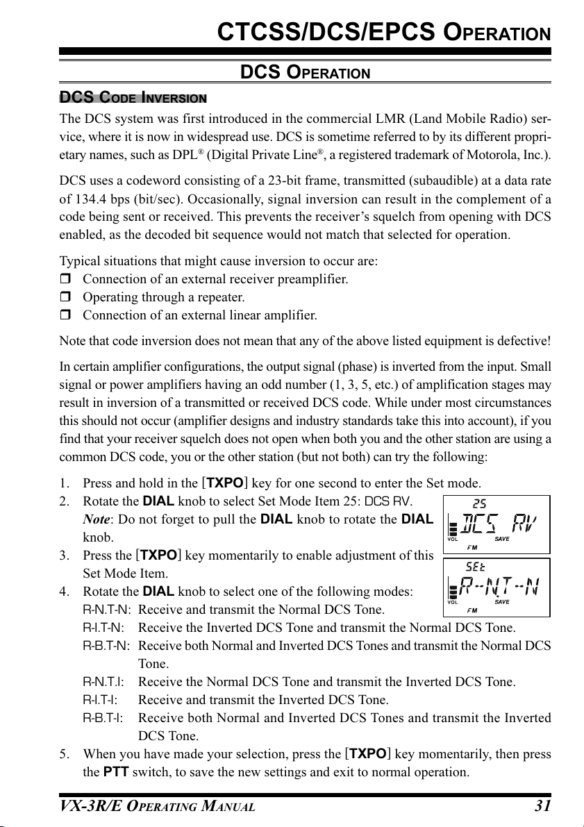
1. Press and hold in the [TXPO] key for one second to enter the Set mode.
2. Rotate the DIAL knob to select Set Mode Item 25: DCS RV.
Note: Do not forget to pull the DIAL knob to rotate the DIAL
knob.
3. Press the [TXPO] key momentarily to enable adjustment of this
Set Mode Item.
4. Rotate the DIAL knob to select one of the following modes:
R-N.T-N: Receive and transmit the Normal DCS Tone.
R-I.T-N: Receive the Inverted DCS Tone and transmit the Normal DCS Tone.
R-B.T-N: Receive both Normal and Inverted DCS Tones and transmit the Normal DCS
Tone.
R-N.T.I: Receive the Normal DCS Tone and transmit the Inverted DCS Tone.
R-I.T-I: Receive and transmit the Inverted DCS Tone.
R-B.T-I: Receive both Normal and Inverted DCS Tones and transmit the Inverted
DCS Tone.
5. When you have made your selection, press the [TXPO] key momentarily, then press
the PTT switch, to save the new settings and exit to normal operation.
VX-3R/E OPERATING MANUAL 31

CTCSS/DCS/EPCS OPERATION
DCS OPERATION
This is different from the usual method of restoring normal operation, and it applies only to
the configuration of the CTCSS/DCS frequencies. Remember to restore the default setting
“R-N.T-N” (Receive and transmit the Normal DCS Tone) when done.
TONE SEARCH SCANNING
In operating situations where you don’t know the CTCSS or DCS tone being used by
another station or stations, you can command the radio to listen to the incoming signal and
scan in search of the tone being used. Two things must be remembered in this regard:
You must be sure that your repeater uses the same tone type (CTCSS vs. DCS).
Some repeaters do not pass the CTCSS tone. You may have to listen to the station(s)
transmitting on the repeater uplink (input) frequency in order to allow Tone Search
Scanning to work.
To scan for the tone in use:
1. Set the radio up for either CTCSS or DCS
Decoder operation (see the previous discus-
sions). In the case of CTCSS, “ ” will
appear on the display; in the case of DCS,
“ ” will appear on the display.
2. Press and hold in the [TXPO] key for one second to enter the Set mode.
3. Rotate the DIAL knob to select Set Mode
Item 86: TN FRQ when TONE SQL is se-
lected, or Set Mode Item 24: DCS CD dur-
ing DCS operation.
Note: Do not forget to pull the DIAL knob to rotate the DIAL knob.
4. Press the [TXPO] key momentarily to enable
adjustment of the selected Set Mode Item.
5. Press and hold in the [BAND] key for one
second, until “T SRCH” (for CTCSS Tone
Search) or “D SRCH” (for DCS Tone Search)
appears on the display, then release the
[
BAND] key to start scanning for the incom-
ing CTCSS or DCS tone/code.
6. When the radio detects the correct tone or code, it will halt on that tone/code, and
audio will be allowed to pass. Press the [BAND] key to lock in that tone/code, then
press and hold the [TXPO
] key for one second
to exit to normal operation.
VX-3R/E OPERATING MANUAL32

CTCSS/DCS/EPCS OPERATION
TONE SEARCH SCANNING
If the Tone Scan feature does not detect a tone or code, it will continue to
scan indefinitely. When this happens, it may be that the other station is not
sending any tone. You can press the PTT switch to halt the scan at any time.
You may listen to the (muted) signal from the other station during Tone Scanning when Set
Mode Item 88: TS MUT is set to “OFF.” See page 121 for details. You can also change the
Tone Search scanning speed, using Set Mode Item 89: TS SPD. See page 121.
Tone Scanning works either in the VFO or Memory modes.
VX-3R/E OPERATING MANUAL 33

CTCSS/DCS/EPCS OPERATION
EPCS (ENHANCED PAGING & CODE SQUELCH
The VX-3R/E includes an Enhanced CTCSS tone encoder/decoder and a dedicated micro-
processor providing paging and selective calling features. This allows you to place a call to
a specific station (Paging), and to receive calls of your choice directed only to you (Code
Squelch).
The paging and code squelch systems use two pairs of (alternately switched) CTCSS tones
which are stored in the pager memories. Basically, your receiver remains silent until it
receives the CTCSS tone pair that matches those stored in the Receiving Pager Memory.
The squelch then opens so the caller is heard, and the paging ringer immediately sounds, if
activated. When you close the PTT switch to transmit, the CTCSS tone pair that is stored
in the Transmitting Pager Memory will be transmitted automatically.
On the paged radio, the Code Squelch will close automatically after the incoming page
ends. Meanwhile, on the paging radio, the Enhanced Paging and Code Squelch system will
be disabled after the PTT switch is released after the paging transmission. You may re-
activate the Enhanced Paging and Code Squelch system again.
)
STORING THE CTCSS TONE PAIRS FOR EPCS OPERATION
1. Press and hold in the [TXPO] key for one second to enter the Set mode.
2. Rotate the DIAL knob to select Set Mode
Item 61: PAG.CDR for the Receiving CTCSS
Tone Pair or Set Mode Item 62: PAG.CDT
for the Transmitting CTCSS Tone Pair.
Note: Do not forget to pull the DIAL knob to rotate the DIAL
knob.
3. Press the [TXPO] key momentarily to enable adjustment of this
Set Mode Item.
4. Rotate the DIAL knob to set the CTCSS Tone number which
corresponds to the first tone of the CTCSS Tone Pair.
5. Press the [V/M] key, then rotate the DIAL knob to set the CTCSS
Tone number which corresponds to the second tone of the CTCSS
Tone Pair.
6. Press the PTT switch to save the new setting and exit to normal
operation.
The VX-3R/E does not recognize the order of the 1st
tone and the 2nd tone. In other words, for example, the
VX-3R/E considers both CTCSS pairs “10, 35” and “35,
10” to be identical.
VX-3R/E OPERATING MANUAL34

CTCSS/DCS/EPCS OPERATION
EPCS (ENHANCED PAGING & CODE SQUELCH
)
ACTIVATING THE ENHANCED PAGING & CODE SQUELCH SYSTEM
1. Press the [F/W] key, then press the [MODE] key. This provides a “Short-cut” to Set
Mode Item 79: SQ TYP.
2. Rotate the DIAL knob until “PAGER” appears on the display.
This activates Enhanced Paging & Code Squelch.
Note: Do not forget to pull the DIAL knob to rotate the DIAL
knob.
3. Press the PTT switch to save the new setting and activate the Enhanced Paging &
Code Squelch.
To disable the Enhanced Paging & Code Squelch, just repeat the above procedure, rotate
the DIAL knob to select “OFF” in step 2 above.
When the Enhanced Paging & Code Squelch feature is activated, the
“P” notation will appear at the 100 MHz digit of the frequency dis-
play.
During Enhanced Paging & Code Squelch operation, you may set up the
VX-3R/E so that a ringing “bell” sound alerts you when a call is coming in.
See page 37 for details.
CTCSS TONE NUMBER
Hz
No.
01
02
03
04
05
06
07
08
09
10
67.0
69.3
71.9
74.4
77.0
79.7
82.5
85.4
88.5
91.5
No.
11
12
13
14
15
16
17
18
19
20
Hz
94.8
97.4
100.0
103.5
107.2
110.9
114.8
118.8
123.0
127.3
No.
21
22
23
24
25
26
27
28
29
30
Hz
131.8
136.5
141.3
146.2
151.4
156.7
159.8
162.2
165.5
167.9
No.
31
32
33
34
35
36
37
38
39
40
Hz
171.3
173.8
177.3
179.9
183.5
186.2
189.9
192.8
196.6
199.5
No.
41
42
43
44
45
46
47
48
49
50
Hz
203.5
206.5
210.7
218.1
225.7
229.1
233.6
241.8
250.3
254.1
VX-3R/E OPERATING MANUAL 35
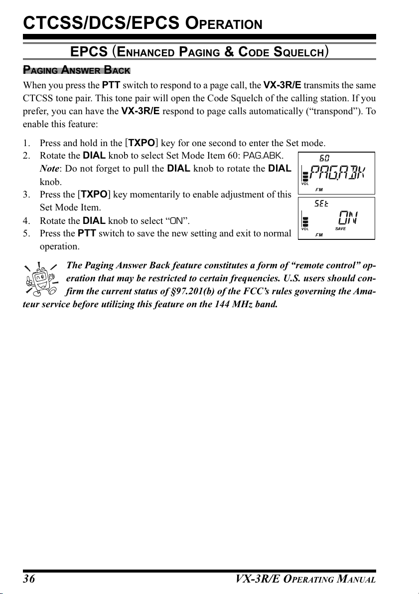
CTCSS/DCS/EPCS OPERATION
EPCS (ENHANCED PAGING & CODE SQUELCH
)
PAGING ANSWER BACK
When you press the PTT switch to respond to a page call, the VX-3R/E transmits the same
CTCSS tone pair. This tone pair will open the Code Squelch of the calling station. If you
prefer, you can have the VX-3R/E respond to page calls automatically (“transpond”). To
enable this feature:
1. Press and hold in the [TXPO] key for one second to enter the Set mode.
2. Rotate the DIAL knob to select Set Mode Item 60: PAG.ABK.
Note: Do not forget to pull the DIAL knob to rotate the DIAL
knob.
3. Press the [TXPO] key momentarily to enable adjustment of this
Set Mode Item.
4. Rotate the DIAL knob to select “ON”.
5. Press the PTT switch to save the new setting and exit to normal
operation.
The Paging Answer Back feature constitutes a form of “remote control” op-
eration that may be restricted to certain frequencies. U.S. users should con-
firm the current status of §97.201(b) of the FCC’s rules governing the Ama-
teur service before utilizing this feature on the 144 MHz band.
VX-3R/E OPERATING MANUAL36

CTCSS/DCS/EPCS OPERATION
CTCSS/DCS/EPCS BELL OPERATION
During CTCSS Decode, DCS, or EPCS operation, you may set up the VX-3R/E so a
ringing “bell” sound (or user programmed beep) alerts you to an incoming call. Here is the
procedure for activating the CTCSS/DCS/EPCS Bell:
1. Set the operating frequency to the desired channel.
2. Set the transceiver up for CTCSS Decode (“Tone Squelch”), DCS, or EPCS opera-
tion, as described previously.
3. Press and hold in the [TXPO] key for one second to enter the Set mode.
4. Rotate the DIAL knob to select Set Mode Item 10: BEL.SEL.
Note: Do not forget to pull the DIAL knob to rotate the DIAL
knob.
5. Press the [TXPO] key momentarily to enable adjustment of this
Set Mode Item.
6. Rotate the DIAL knob to set the desired “bell” sound. The available choices are BELL,
USERBP1, USERBP2, USERBP3, or OFF (disable the Bell func-
tion).
Note: When User Beep (described later) does not register,
USERBP1, USERBP2, or USERBP3 does not appear.
7. Press the [TXPO] key momentarily, then rotate the DIAL knob
one click counter-clockwise to select Set Mode Item 9: BEL.RNG.
8. Press the [TXPO] key momentarily to enable adjustment of this
Set Mode Item.
9. Rotate the DIAL knob to set the desired number of rings of the
Bell. The available choices are 1 through 20 rings or CONT (con-
tinuous ringing).
10. Press the PTT switch momentarily to save the new setting and exit to normal opera-
tion.
When you are called by a station whose transceiver is sending a CTCSS tone, DCS code,
or CTCSS tone pair which matches that set into your Decoder, the Bell will ring in accor-
dance with this programming.
When the CTCSS/DCS/EPCS Bell is activated, the “ ” icon will
appear in the display.
To disable the CTCSS/DCS/EPCS Bell function, select the setting of
Set Mode Item 10: BEL.SEL to “OFF”.
VX-3R/E OPERATING MANUAL 37

CTCSS/DCS/EPCS OPERATION
CTCSS/DCS/EPCS BELL OPERATION
PROGRAMMING THE USER BEEP
Three User Beep Memories are provided, allowing you to create a unique original beep
tone.
Each User Beep Memory can store up to 64 steps with three octaves (“C1” through “B3”).
1. Press and hold in the [TXPO] key for one second to enter the Set mode.
2. Rotate the DIAL knob to select Set Mode Item 15: BP USR.
Note: Do not forget to pull the DIAL knob to rotate the DIAL
knob.
3. Press the [TXPO] key momentarily to enable adjustment of this
Set Mode Item.
4. Rotate the DIAL knob to select the memory slot into which you
wish to store your programmed beep. Available selections are
bP1, bP2, and bP3. The previously stored beep will be displayed.
5. Press the [V/M] key to enable programming the beep. Press and hold the [HM/RV
key for one second to clear any previous beep, if desired.
6. Rotate the DIAL knob to select the first beep tone of the User
Beep.
7. Press the [V/M] key, then rotate the DIAL knob to set the length
of the first beep tone. Available selections are 1 (0.1 sec) - 250
(2.5 sec).
8. Press the [V/M] key to accept the first beep tone of the User Beep.
9. If you make a mistake, press the [BAND] key to back-space the cursor, then re-enter
the correct beep tone or length.
10. Repeat steps 6 - 9 until you have completed the User Beep.
11. When there is a beep tone which you wish to delete, bring the cursor to that beep tone
using the [BAND]/[V/M] key, then press the [MODE] key repeatedly until the “dEL”
notation appears in the Memory Channel Number display slot. Press and hold in the
[
MODE] key for one second to delete that beep tone.
12. When you wish to add a beep tone into the beep tone strings, move the cursor to the
desired place where you wish to enter the beep tone using the [BAND]/[V/M] key,
then press the [MODE] key repeatedly untill the “InS” notation is displayed in the
Memory Channel Number display slot. Press and hold in the [MODE] key for one
second to add the beep tone.
Beep Tone
Tone Length
]
C2C1 C3D2D1 D3E2E1 E3F2F1 F3G2G1 G3A2A1 A3B2B1 B3
VX-3R/E OPERATING MANUAL38

CTCSS/DCS/EPCS OPERATION
CTCSS/DCS/EPCS BELL OPERATION
13. Press and hold the [HM/RV] key for one second to delete all data after the current
position that may have previously been stored in the User Beep.
14. When you have programmed User Beep, press the [TXPO] key momentarily to con-
firm the User Beep.
You may check your work by monitoring the programmed User Beep. To do
this, repeat steps 1 - 4 above, then press the [F/W] key.
SPLIT TONE OPERATION
The VX-3R/E can be operated in a Split Tone configuration via the Set mode.
1. Press and hold in the [TXPO] key for one second to enter the Set mode.
2. Rotate the DIAL knob to select Set Mode Item 81: SQSPLT.
Note: Do not forget to pull the DIAL knob to rotate the DIAL
knob.
3. Press the [TXPO] key momentarily to enable adjustment of this
Set Mode Item.
4. Rotate the DIAL knob to select “ON” (to enable the Split Tone
feature).
5. Press the PTT switch momentarily to save the new setting and exit to normal opera-
tion.
When the Split Tone feature is activated, you can see the following additional parameters
after the “MESSAGE” parameter while selecting the Set Mode Item 79: SQ TYP:
D CODE: DCS Encode only
(the “ ” icon will blink during operation)
T DCS: Encodes a CTCSS Tone and Decodes a DCS code
(the “ ” icon will blink and the “ ” icon will appear during operation)
D TONE: Encodes a DCS code and Decodes a CTCSS Tone
(the “ ” icon will appear and the “ ” icon will blink during operation)
Select the desired operating mode, from the selections shown above, within Set Mode Item
79: SQ TYP.
VX-3R/E OPERATING MANUAL 39

NOTE
VX-3R/E OPERATING MANUAL40

MEMORY MODE
The VX-3R/E provides a wide variety of memory system resources. These include:
“Regular” Memory Channels, which include:
900 “Standard” memory channels, numbered “1” through “900.”
99 “Frequency Skip Memories,” numbered “901” through “999.”
11 “Home” channels, providing storage and quick recall of one prime frequency
on each operating band.
50 sets of band-edge memories, also known as “Programmable Memory Scan”
channels, labeled “L01/U01” through “L50/U50.”
24 Memory Banks, labeled “b 1” through “b24.” Each Memory Bank can be
assigned up to 100 channels from the “regular” memory channels.
Special Memory Channels, which include:
One “Emergency Automatic ID (EAI)” Channel.
10 “Weather Broadcast” Channels.
57 VHF Marine Channels.
89 popular Short-wave Broadcast Station Memory Channels.
Standard Memory Channels
(900 channels)
9
8
8
4
3
2
1
EAI Channel
(1 channel)
Weather Broadcast Channels
(10 channels)
9
X
4
3
2
X
1
X
X
W
W
W
W
X
W
Frequency Skip Memory Channels
0
0
9
0
1
X
W
(99 channels)
2
1
0
0
9
9
I
A
E
VHF Marine Channels
(57 channels)
4
3
0
0
9
9
9
8
9
9
9
9
HOME Channels
(11 channels)
d
d
n
d
n
a
n
a
B
a
B
B
W
C
S
C
B
B
M
M
F
A
Short-wave Broadcast Station
PMS Memory Channels
(50 Sets)
4
3
U
2
/
U
1
/
4
U
/
3
U
L
/
2
L
1
L
L
2
-
d
d
d
n
1
n
n
a
-
d
d
n
d
n
a
d
n
a
B
n
a
B
a
V
B
z
B
T
r
i
-
H
z
F
A
M
H
H
4
M
V
4
0
1
5
Memory Channels
(89 channels)
a
a
B
d
B
B
n
V
.
a
z
o
T
B
f
-
H
.
n
F
I
M
o
f
H
0
n
U
I
3
4
0
9
5
4
U
/
U
/
0
9
5
4
L
L
VX-3R/E OPERATING MANUAL 41

MEMORY MODE
(
REGULAR MEMORY CHANNEL OPERATION
)
MEMORY STORAGE
1. Select the desired frequency while operating in the VFO mode. Be sure to set up any
desired CTCSS or DCS tones, as well as any desired repeater offset. The power level
may also be set at this time, if you wish to store it.
2. Press and hold in the [F/W] key for 1/2 seconds.
3. Within five seconds of releasing the [F/W] key, you need to make a decision regarding
channel storage. The microprocessor will automatically select the next-available “free”
channel (a memory register on which no data has been stored). If you do not wish to
make a change and accept the “free” channel, proceed to step 4. If you wish to select a
different channel number into which to store the data, rotate the DIAL knob to select
the desired memory channel.
Note: Do not forget to pull the DIAL knob to rotate the DIAL knob.
Advice: You may jump 100 memory channels, if you’re in a hurry (101
by pressing the [TXPO] key (multiple times, if necessary). Any channel that you see
with a blinking channel number currently has no data written on it (i.e. the channel is
“free”).
4. Press the [F/W] key once more to store the frequency into memory.
5. You will still be operating in the “VFO” mode, so you may now enter other frequen-
cies, and store them into additional memory locations, by repeating the above process.
1) You may change the automatic memory channel selection feature to select
the “next-highest memory channel above the last-stored memory channel”
instead of the “next-available ‘free’ channel” via the Set Mode Item 50: MR
WMD; see page 114.
2) You may disable the memory write function which prevents a memory write operation
if you should accidentally perform a wrong key sequence via the Set Mode Item 53:
MRPTCT. See page 116 for details. When the memory write protect is activated, the
“PROTCT” notation appears on the display while a memory write operation is being
performed.
201 301
…
),
IMPORTANT NOTE
On rare occasions the memorized data may become corrupted by miss operation, or
static electricity. When repairs are made the memory data may be lost. Please write
down or record the memorized information so you will be able to restore it if needed.
VX-3R/E OPERATING MANUAL42
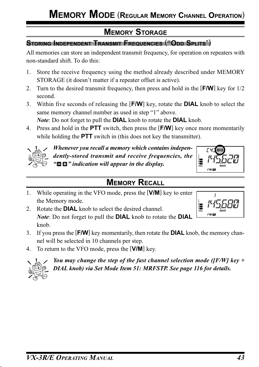
MEMORY MODE
(
REGULAR MEMORY CHANNEL OPERATION
MEMORY STORAGE
STORING INDEPENDENT TRANSMIT FREQUENCIES (“ODD SPLITS”
All memories can store an independent transmit frequency, for operation on repeaters with
non-standard shift. To do this:
1. Store the receive frequency using the method already described under MEMORY
STORAGE (it doesn’t matter if a repeater offset is active).
2. Turn to the desired transmit frequency, then press and hold in the [F/W] key for 1/2
second.
3. Within five seconds of releasing the [F/W] key, rotate the DIAL knob to select the
same memory channel number as used in step “1” above.
Note: Do not forget to pull the DIAL knob to rotate the DIAL knob.
4. Press and hold in the PTT switch, then press the [F/W] key once more momentarily
while holding the PTT switch in (this does not key the transmitter).
Whenever you recall a memory which contains indepen-
dently-stored transmit and receive frequencies, the
“ ” indication will appear in the display.
)
MEMORY RECALL
1. While operating in the VFO mode, press the [V/M] key to enter
the Memory mode.
2. Rotate the DIAL knob to select the desired channel.
Note: Do not forget to pull the DIAL knob to rotate the DIAL
knob.
3. If you press the [F/W] key momentarily, then rotate the DIAL knob, the memory chan-
nel will be selected in 10 channels per step.
4. To return to the VFO mode, press the [V/M] key.
)
You may change the step of the fast channel selection mode ([F/W] key +
DIAL knob) via Set Mode Item 51: MRFSTP. See page 116 for details.
VX-3R/E OPERATING MANUAL 43
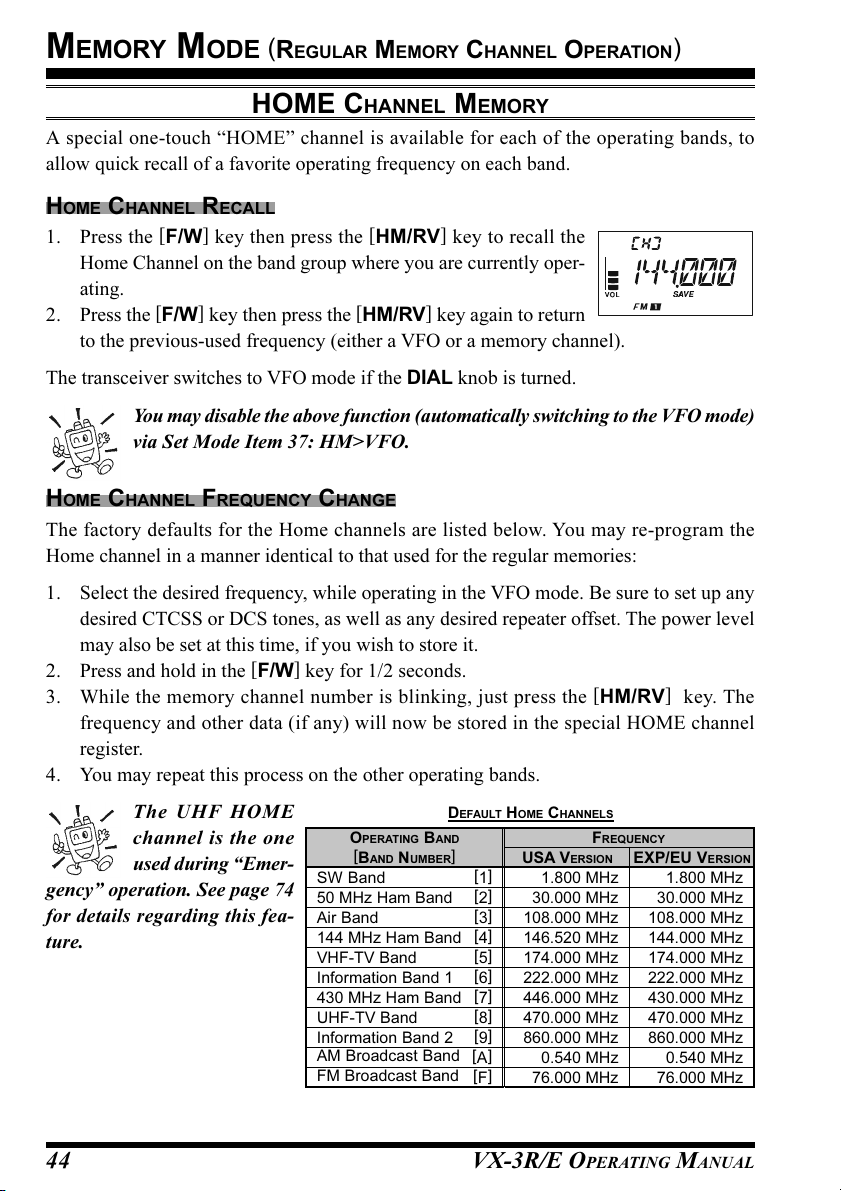
MEMORY MODE
(
REGULAR MEMORY CHANNEL OPERATION
)
HOME CHANNEL MEMORY
A special one-touch “HOME” channel is available for each of the operating bands, to
allow quick recall of a favorite operating frequency on each band.
HOME CHANNEL RECALL
1. Press the [F/W] key then press the [HM/RV] key to recall the
Home Channel on the band group where you are currently oper-
ating.
2. Press the [F/W] key then press the [HM/RV] key again to return
to the previous-used frequency (either a VFO or a memory channel).
The transceiver switches to VFO mode if the DIAL knob is turned.
You may disable the above function (automatically switching to the VFO mode)
via Set Mode Item 37: HM>VFO.
HOME CHANNEL FREQUENCY CHANGE
The factory defaults for the Home channels are listed below. You may re-program the
Home channel in a manner identical to that used for the regular memories:
1. Select the desired frequency, while operating in the VFO mode. Be sure to set up any
desired CTCSS or DCS tones, as well as any desired repeater offset. The power level
may also be set at this time, if you wish to store it.
2. Press and hold in the [F/W] key for 1/2 seconds.
3. While the memory channel number is blinking, just press the [HM/RV] key. The
frequency and other data (if any) will now be stored in the special HOME channel
register.
4. You may repeat this process on the other operating bands.
The UHF HOME
channel is the one
used during “Emer-
gency” operation. See page 74
for details regarding this fea-
ture.
DEFAULT HOME CHANNELS
OPERATING BAND
[
BAND NUMBER
SW Band
50 MHz Ham Band[2
Air Band
144 MHz Ham Band[4
VHF-TV Band
Information Band 1[6
430 MHz Ham Band[7
UHF-TV Band
Information Band 2[9
AM Broadcast Band [A]
FM Broadcast Band [F]
]
[1]
[3]
[5]
[8]
VX-3R/E OPERATING MANUAL44
USA VERSION
]
108.000 MHz
]
146.520 MHz
174.000 MHz
]
222.000 MHz
]
446.000 MHz
470.000 MHz
]
860.000 MHz
FREQUENCY
1.800 MHz
30.000 MHz
0.540 MHz
76.000 MHz
EXP/EU VERSION
1.800 MHz
30.000 MHz
108.000 MHz
144.000 MHz
174.000 MHz
222.000 MHz
430.000 MHz
470.000 MHz
860.000 MHz
0.540 MHz
76.000 MHz
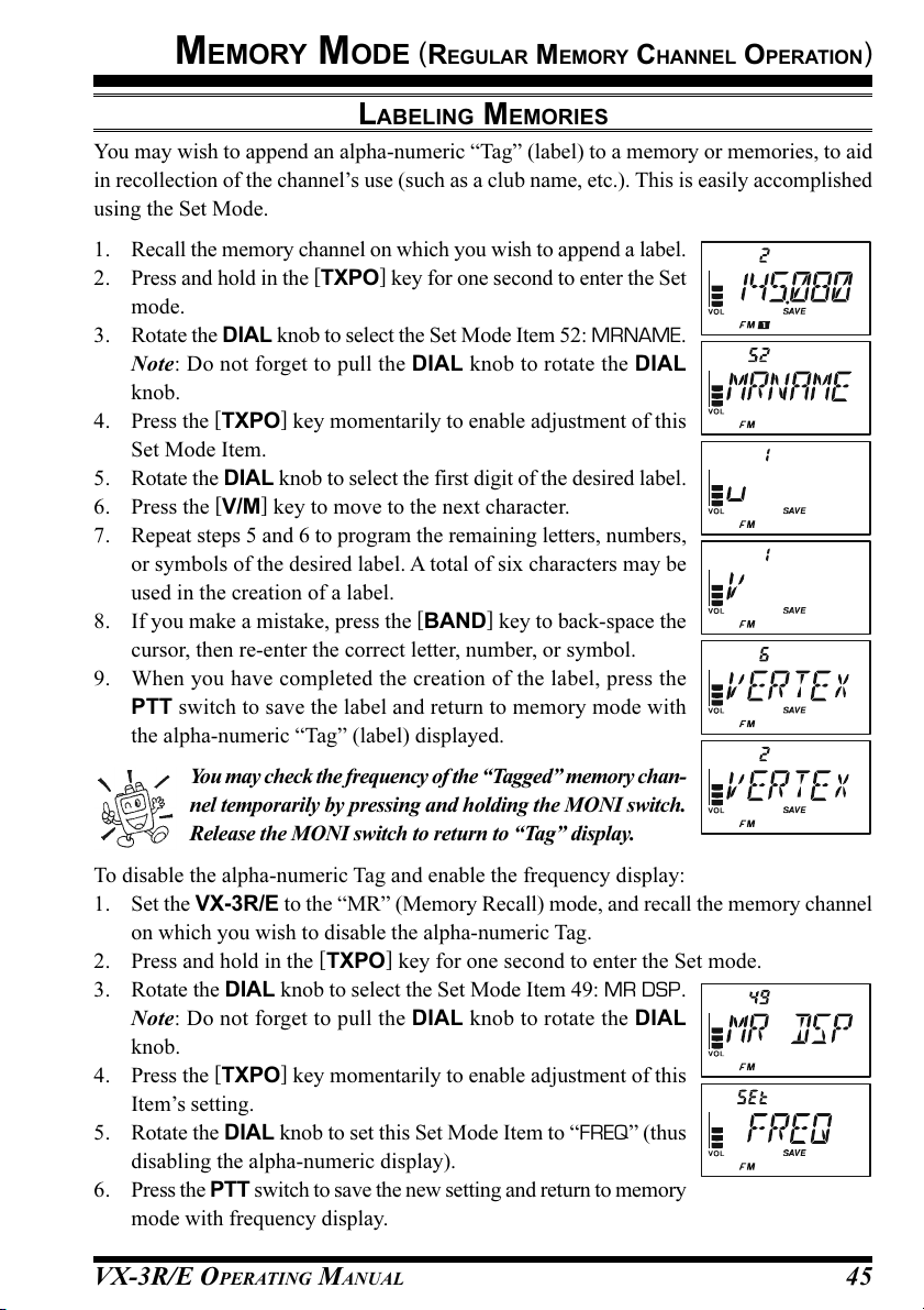
MEMORY MODE
(
REGULAR MEMORY CHANNEL OPERATION
LABELING MEMORIES
You may wish to append an alpha-numeric “Tag” (label) to a memory or memories, to aid
in recollection of the channel’s use (such as a club name, etc.). This is easily accomplished
using the Set Mode.
1. Recall the memory channel on which you wish to append a label.
2. Press and hold in the [TXPO] key for one second to enter the Set
mode.
3. Rotate the DIAL knob to select the Set Mode Item 52: MRNAME.
Note: Do not forget to pull the DIAL knob to rotate the DIAL
knob.
4. Press the [TXPO] key momentarily to enable adjustment of this
Set Mode Item.
5. Rotate the DIAL knob to select the first digit of the desired label.
6. Press the [V/M] key to move to the next character.
7. Repeat steps 5 and 6 to program the remaining letters, numbers,
or symbols of the desired label. A total of six characters may be
used in the creation of a label.
8. If you make a mistake, press the [BAND] key to back-space the
cursor, then re-enter the correct letter, number, or symbol.
9. When you have completed the creation of the label, press the
PTT switch to save the label and return to memory mode with
the alpha-numeric “Tag” (label) displayed.
)
You may check the frequency of the “Tagged” memory chan-
nel temporarily by pressing and holding the MONI switch.
Release the MONI switch to return to “Tag” display.
To disable the alpha-numeric Tag and enable the frequency display:
1. Set the VX-3R/E to the “MR” (Memory Recall) mode, and recall the memory channel
on which you wish to disable the alpha-numeric Tag.
2. Press and hold in the [TXPO] key for one second to enter the Set mode.
3. Rotate the DIAL knob to select the Set Mode Item 49: MR DSP.
Note: Do not forget to pull the DIAL knob to rotate the DIAL
knob.
4. Press the [TXPO] key momentarily to enable adjustment of this
Item’s setting.
5. Rotate the DIAL knob to set this Set Mode Item to “FREQ” (thus
disabling the alpha-numeric display).
6. Press the PTT switch to save the new setting and return to memory
mode with frequency display.
VX-3R/E OPERATING MANUAL 45

MEMORY MODE
(
REGULAR MEMORY CHANNEL OPERATION
)
LABELING MEMORIES
To enable the alpha-numeric Tag (label) display again, just repeat the above procedure,
rotating the DIAL knob to select “ALPHA” in step 5 above.
You may set up some memory channels to have their frequencies displayed,
while others may be set to have their Name Tag displayed. The selection within
Set Mode Item 49: MR DSP is not applied to all memory channels at once.
MEMORY OFFSET TUNING
Once you have recalled a particular memory channel, you may easily tune off that channel,
as though you were in the “VFO” mode.
1. With the VX-3R/E in the “MR” (Memory Recall) mode, select the desired memory
channel.
2. Press the [F/W] key, then press the [V/M] key to activate the
“Memory Tuning” feature. The Memory Channel number will
be replaced by “tun.”
3. Rotate the DIAL knob, as desired, to tune to a new frequency.
The synthesizer steps selected for VFO operation on the current band will be the steps
used during Memory Tuning.
Note: Do not forget to pull the DIAL knob to rotate the DIAL knob.
4. If you wish to return to the original memory frequency, just press the [V/M] key mo-
mentarily.
5. If you wish to store a new frequency set during Memory Tuning, just press and hold in
the [F/W] key for 1/2 seconds, per normal memory storage procedure. The micropro-
cessor will automatically set itself to the next-available clear memory location, and
you then press [F/W] again to lock in the new frequency.
1) If you want to replace the original memory contents with those of the new
frequency, be sure to rotate the DIAL knob to the original memory channel
number!
2) Any required CTCSS/DCS changes, or repeater-offset modifications, must be done
before storing the data into the new (or original) memory channel location.
VX-3R/E OPERATING MANUAL46
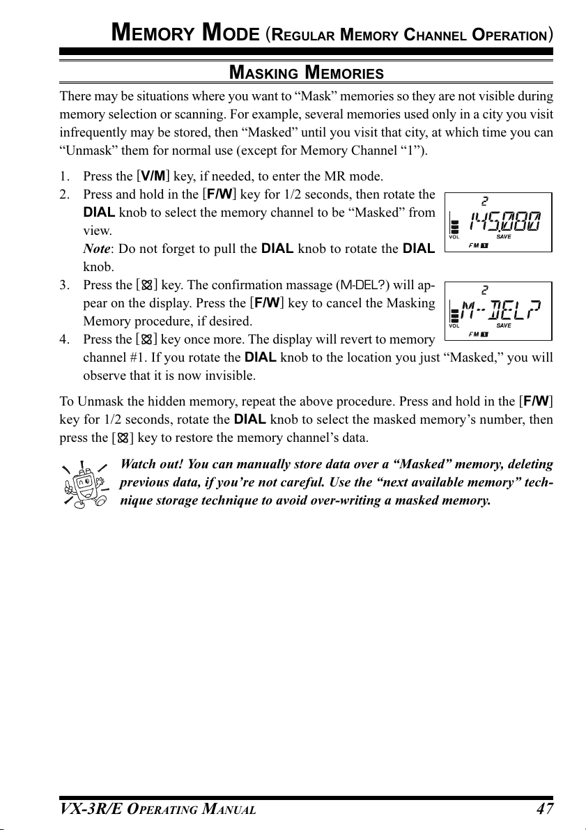
MEMORY MODE
(
REGULAR MEMORY CHANNEL OPERATION
MASKING MEMORIES
There may be situations where you want to “Mask” memories so they are not visible during
memory selection or scanning. For example, several memories used only in a city you visit
infrequently may be stored, then “Masked” until you visit that city, at which time you can
“Unmask” them for normal use (except for Memory Channel “1”).
1. Press the [V/M] key, if needed, to enter the MR mode.
2. Press and hold in the [F/W] key for 1/2 seconds, then rotate the
DIAL knob to select the memory channel to be “Masked” from
view.
Note: Do not forget to pull the DIAL knob to rotate the DIAL
knob.
3. Press the
pear on the display. Press the [F/W] key to cancel the Masking
Memory procedure, if desired.
4. Press the
channel #1. If you rotate the DIAL knob to the location you just “Masked,” you will
observe that it is now invisible.
[ ]
key. The confirmation massage (M-DEL?) will ap-
[ ]
key once more. The display will revert to memory
)
To Unmask the hidden memory, repeat the above procedure. Press and hold in the [F/W
key for 1/2 seconds, rotate the DIAL knob to select the masked memory’s number, then
press the [ ] key to restore the memory channel’s data.
Watch out! You can manually store data over a “Masked” memory, deleting
previous data, if you’re not careful. Use the “next available memory” tech-
nique storage technique to avoid over-writing a masked memory.
]
VX-3R/E OPERATING MANUAL 47

MEMORY MODE
(
REGULAR MEMORY CHANNEL OPERATION
)
MEMORY BANK OPERATION
The large number of memories available in the VX-3R/E could be difficult to utilize
without some means of organizing them. Fortunately, the VX-3R/E includes provision for
dividing the memories into as many as 24 Memory Groups, so you can categorize the
memories in a manner convenient to you. You may enter and exit the “Memory Group”
mode by a single press of the [BAND] key, as we shall see below.
ASSIGNING MEMORIES TO A MEMORY BANK
1. Recall the memory channel to be assigned to a Memory Bank.
2. Press and hold in the [F/W] key for 1/2 seconds, then rotate the
DIAL knob to select the Memory Bank number you want as the
Memory Bank for this channel (“b 1” ~ “b24,” which is found
before memory channel “1”).
Note: Do not forget to pull the DIAL knob to rotate the DIAL
knob.
3. Press the [F/W] key mo-
mentarily.
4. At this point, the memory
channel data is copied into
the Memory Bank.
Memory Channel
CH 1 145. 000 MHz
CH 2 145. 500 MHz
CH 3 435. 000 MHz
CH 4 435. 500 MHz
CH 5 145. 800 MHz
CH 6 436. 000 MHz
CH 7 128. 800 MHz
1) You may assign
one memory chan-
nel into several
CH 897 145.620 MHz
CH 898 436.780 MHz
CH 899 128.600 MHz
Memory Banks.
2) The PMS memory channels (L1/U1 through L50/U50) may not be assigned to a
Memory Bank.
Memory Bank “1”
144 MHz Amateur Band Channels
Memory Bank “2”
430 MHz Amateur Band Channels
Memory Bank “3”
All Amateur Band Channels
Memory Bank “4”
Club Channels
Memory Bank “5”
Air Band Cha nnels
MEMORY BANK RECALL
1. Press the [V/M] key, if needed, to enter the MR mode.
2. Press the [BAND] key to activate the “Memory Bank” mode.
The “ ” icon and Memory Bank number will appear on the
display.
3. Press the [F/W] key, and then press the [BAND] key.
4. Rotate the DIAL knob to select the desired Memory Bank (“BANK
1” through “BANK 24”).
Note: Do not forget to pull the DIAL knob to rotate the DIAL
knob.
5. Press the [BAND] key. Now, as you rotate the DIAL knob to
select memories, you will observe that you can only select memory
channels in the current memory bank.
VX-3R/E OPERATING MANUAL48

MEMORY MODE
(
REGULAR MEMORY CHANNEL OPERATION
MEMORY BANK OPERATION
6. To change to another Memory Bank, press the [F/W] key, then
press the [BAND] key. Now rotate the DIAL knob to select the
new Memory Bank, then press the [BAND] key again.
7. To exit from Memory Bank operation, just press the [BAND
key. The “ ” icon will disappear from the display, that you
are now in the “regular” Memory Recall mode, without utiliza-
tion of the Memory Banks. The memories stored in the various
Banks will remain in those banks. You do not need to store them again.
REMOVING MEMORIES FROM A MEMORY BANK
1. Recall the memory channel to be removed from a Memory Bank.
2. Press and hold the [F/W] key for one second, then press the
memory channel data from the Memory bank.
]
[ ]
)
key to remove the
CHANGING A MEMORY BANK
You may change the default Memory Bank Names, which are shown on the display while
selecting the Memory Bank your desire.
1. Press and hold in the [TXPO] key for one second to enter the Set mode.
2. Rotate the DIAL knob to select the Set Mode Item labeled 11:
BNK.NAM.
Note: Do not forget to pull the DIAL knob to rotate the DIAL
knob.
3. Press the [TXPO] key momentarily to enable adjustment of this Set Mode Item.
4. Rotate the DIAL knob to select the memory bank on which you
wish to change a label.
5. Press the [TXPO] key momentarily to enable changing of the
name tag.
6. Rotate the DIAL knob to select the first digit of the desired label.
7. Press the [V/M] key to move to the next character.
8. Repeat steps 6 and 7 to program the remaining letters, numbers,
or symbols of the desired label. A total of six characters may be
used in the creation of a label.
9. If you make a mistake, press the [BAND] key to backspace the
cursor, then re-enter the correct letter, number, or symbol.
10. When you have completed the changes of the label, press the PTT switch to save the
label and exit.
S NAME
’
VX-3R/E OPERATING MANUAL 49

MEMORY MODE
(
REGULAR MEMORY CHANNEL OPERATION
)
MOVING MEMORY DATA TO THE VFO
Data stored on memory channels can easily be moved to the VFO, if you like.
1. Select the memory channel containing the frequency data to be
moved to VFO.
2. Press and hold in the [F/W] key for one second, then press the
[
V/M] key. The confirmation massage (V-WRT?) will appear on
the display. Press the [F/W] key to cancel the Moving Memory
Data procedure, if desired.
3. Press the [V/M] key once more. The data will now have been
copied to the VFO, although the original memory contents will
remain intact on the previously stored channel.
If a Split Frequency Memory channel was transferred,
the Tx frequency will be ignored (you will be set up for Simplex operation on
the Receive frequency).
MEMORY ONLY MODE
Once memory channel programming has been completed, you may place the radio in a
“Memory Only” mode, whereby VFO operation is impossible. This may be particularly
useful during public-service events, where a number of operators may be using the radio
for first time, and ultimate simplicity of channel selection is desired.
To place the radio into the Memory Only mode, turn the radio off. Now press and hold in
the [V/M] key while turning the radio on. To return to normal operation, repeat the above
power-on procedure.
VX-3R/E OPERATING MANUAL50

MEMORY MODE
(
SPECIAL MEMORY CHANNEL OPERATION
The VX-3R/E provides Special Memory Channels, which made up of:
10 “Weather Broadcast” Channels.
281 VHF Marine Channels
89 popular Short-wave Broadcast Station Memory Channels.
You may assign the Special Memory Channels to a Memory Bank. See page 48 regard-
ing Memory Bank Operation for details.
WEATHER BROADCAST CHANNELS
The VHF Weather Broadcast Station Memory Channel Bank has been pre-programmed at
the factory, for quick selection of NOAA weather information stations.
)
1. Press the [F/W] key, then press the
[ ]
key, to recall the Special Memory Menu.
2. Press the [BAND] key, repeatedly if necessary to select the “WX
CH” (thus recalling the Weather Broadcast Memory Bank).
3. Rotate the DIAL knob to select the desired Weather Broadcast
channel.
Note: Do not forget to pull the DIAL knob to rotate the DIAL
knob.
4. If you wish to scan this bank to search for louder stations, just
press the PTT switch. When the scanner pauses
on a station, press the PTT switch once to halt
the scan, or press it twice to restart the scan.
5. To exit to normal operation, press the [V/M] key,
or press [F/W] key followed by the
[ ]
key.
CH
1
162.550 MHz
2
162.400 MHz
3
162.475 MHz
4
162.425 MHz
5
162.450 MHz
FREQUENCY
CH
6
162.500 MHz
7
162.525 MHz
8
161.650 MHz
9
161.775 MHz
10
163.275 MHz
FREQUENCY
1) In the event of extreme weather disturbances, such as storms and hurri-
canes, the NOAA (National Oceanic and Atmospheric Administration) sends
a weather alert accompanied by a 1050 Hz tone and subsequent weather
report on one of the NOAA weather channels. You may disable the Weather Alert tone
via Set Mode Item 93: WX ALT, if desired. See page 122.
2) You may append and display an alpha-numeric “Tag” (label) to a Weather Broadcast
channel or channels. See page 45 regarding the labeling of a memory for details.
VX-3R/E OPERATING MANUAL 51
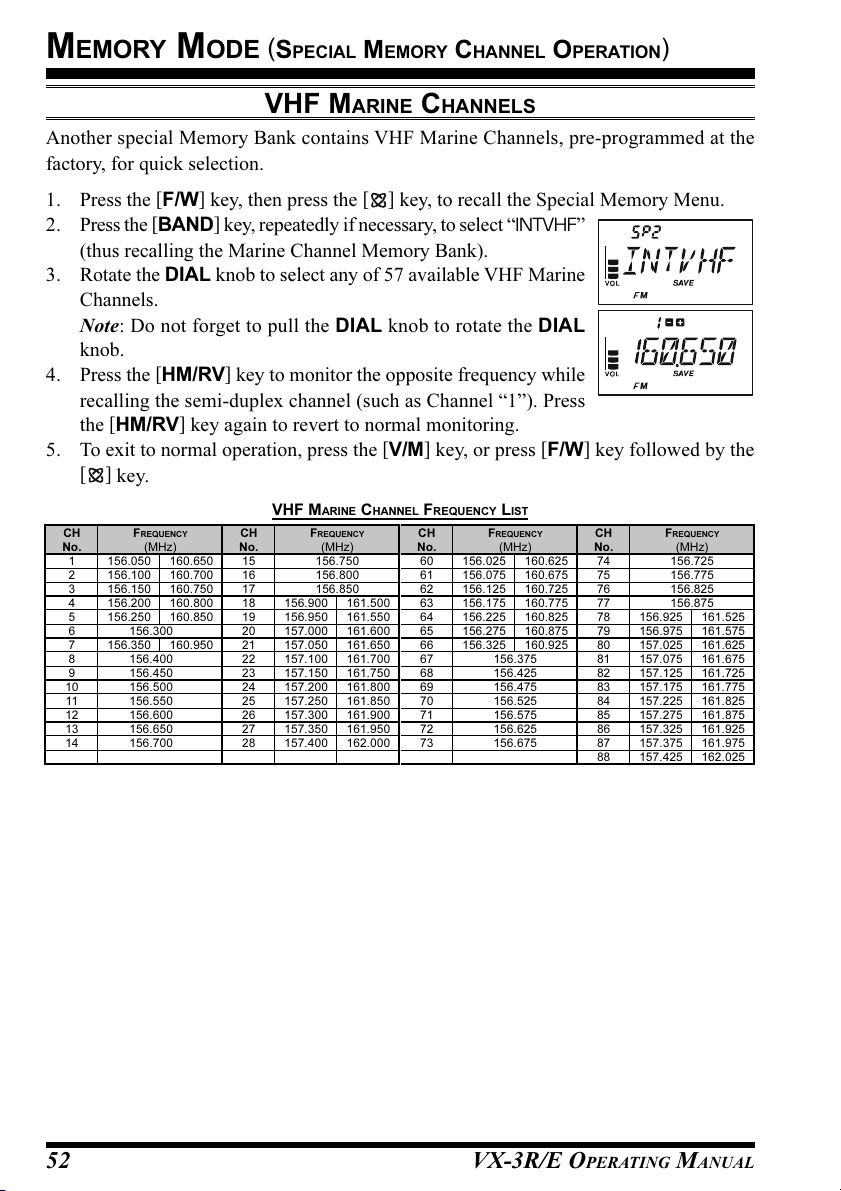
MEMORY MODE
(
SPECIAL MEMORY CHANNEL OPERATION
)
VHF MARINE CHANNELS
Another special Memory Bank contains VHF Marine Channels, pre-programmed at the
factory, for quick selection.
1. Press the [F/W] key, then press the
[ ]
key, to recall the Special Memory Menu.
2. Press the [BAND] key, repeatedly if necessary, to select “INTVHF”
(thus recalling the Marine Channel Memory Bank).
3. Rotate the DIAL knob to select any of 57 available VHF Marine
Channels.
Note: Do not forget to pull the DIAL knob to rotate the DIAL
knob.
4. Press the [HM/RV] key to monitor the opposite frequency while
recalling the semi-duplex channel (such as Channel “1”). Press
the [HM/RV] key again to revert to normal monitoring.
5. To exit to normal operation, press the [V/M] key, or press [F/W] key followed by the
[ ]
key.
VHF MARINE CHANNEL FREQUENCY LIST
CH
No.
1
156.050 160.650
2
156.100 160.700
3
156.150 160.750
4
156.200 160.800
5
156.250 160.850
6
7
156.350 160.950
8
9
10
11
12
13
14
FREQUENCY
(MHz)
156.300
156.400
156.450
156.500
156.550
156.600
156.650
156.700
CH
No.
15
16
17
18
19
20
21
22
23
24
25
26
27
28
FREQUENCY
(MHz)
156.750
156.800
156.850
156.900 161.500
156.950 161.550
157.000 161.600
157.050 161.650
157.100 161.700
157.150 161.750
157.200 161.800
157.250 161.850
157.300 161.900
157.350 161.950
157.400 162.000
CH
No.
60
156.025 160.625
61
156.075 160.675
62
156.125 160.725
63
156.175 160.775
64
156.225 160.825
65
156.275 160.875
66
156.325 160.925
67
68
69
70
71
72
73
FREQUENCY
(MHz)
156.375
156.425
156.475
156.525
156.575
156.625
156.675
CH
No.
74
75
76
77
78
156.925 161.525
79
156.975 161.575
80
157.025 161.625
81
157.075 161.675
82
157.125 161.725
83
157.175 161.775
84
157.225 161.825
85
157.275 161.875
86
157.325 161.925
87
157.375 161.975
88
157.425 162.025
FREQUENCY
(MHz)
156.725
156.775
156.825
156.875
VX-3R/E OPERATING MANUAL52

MEMORY MODE
(
SPECIAL MEMORY CHANNEL OPERATION
SHORT-WAVE BROADCAST STATION MEMORY CHANNELS
A large number of Short-Wave Broadcast Station Memory Channels have also been pre-
programmed at the factory, for convenient selection of broadcast stations.
)
1. Press the [F/W] key, then press the
[ ]
key, to recall the Special Memory Menu.
2. Press the [BAND] key to select “RADIO” (thus recalling the
Broadcast Station Channel Memory Bank).
3. Rotate the DIAL knob to select any of 89 available Broadcast
Stations.
Note: Do not forget to pull the DIAL knob to rotate the DIAL
knob.
4. Press and hold the MONI switch to display the receiving fre-
quency ”Station’s Frequency” (and disabling the squelch). Re-
lease the MONI switch to return to “Station Name” display.
Tag
SPAIN
SPAIN
SPAIN
SPAIN
NIKKEI
NORWAY
NORWAY
NORWAY
NORWAY
SWEDEN
SWEDEN
SWEDEN
SWEDEN
FINLAN
FINLAN
FINLAN
FINLAN
RUSSIA
RUSSIA
RUSSIA
RUSSIA
ISRAEL
ISRAEL
ISRAEL
ISRAEL
INDIA
INDIA
INDIA
INDIA
CHINA
CHINA
CHINA
CHINA
KOREA
KOREA
KOREA
KOREA
JAPAN
JAPAN
JAPAN
JAPAN
AUSTRA
AUSTRA
AUSTRA
AUSTRA
]
Station Name
Radio Exterior de Espana
Radio Exterior de Espana
Radio Exterior de Espana
Radio Exterior de Espana
Radio Nikkei
Radio Norway International
Radio Norway International
Radio Norway International
Radio Norway International
Radio Sweden
Radio Sweden
Radio Sweden
Radio Sweden
Radio Finland
Radio Finland
Radio Finland
Radio Finland
Voice of Russia
Voice of Russia
Voice of Russia
Voice of Russia
Israel Broadcasting Authority
Israel Broadcasting Authority
Israel Broadcasting Authority
Israel Broadcasting Authority
All India Radio (AIR)
All India Radio (AIR)
All India Radio (AIR)
All India Radio (AIR)
China Radio International (CRI)
China Radio International (CRI)
China Radio International (CRI)
China Radio International (CRI)
Radio Korea
Radio Korea
Radio Korea
Radio Korea
Radio Japan
Radio Japan
Radio Japan
Radio Japan
Radio Australia
Radio Australia
Radio Australia
Radio Australia
5. To exit to normal operation, press the [V/M] key, or press [F/W
key followed by the
Ch
Freq.
(MHz)
6.030
6.160
9.760
11.965
9.555
9.600
11.715
11.955
6.195
9.410
12.095
15.310
6.090
9.790
11.670
15.195
6.000
6.075
9.650
9.735
5.990
9.575
9.675
17.780
7.170
7.270
9.560
11.690
9.660
11.625
11.830
15235
5.955
6.020
9.895
11.655
5.985
7.165
9.455
11.860
9.780
11.630
15.550
21.655
MODE
AM
AM
AM
AM
AM
AM
AM
AM
AM
AM
AM
AM
AM
AM
AM
AM
AM
AM
AM
AM
AM
AM
AM
AM
AM
AM
AM
AM
AM
AM
AM
AM
AM
AM
AM
AM
AM
AM
AM
AM
AM
AM
AM
AM
No.
10
11
12
13
14
15
16
17
18
19
20
21
22
23
24
25
26
27
28
29
30
31
32
33
34
35
36
37
38
39
40
41
42
43
44
1
2
3
4
5
6
7
8
9
CANADA
CANADA
CANADA
CANADA
FRANCE
FRANCE
FRANCE
FRANCE
TURKEY
TURKEY
TURKEY
TURKEY
VATICN
VATICN
VATICN
VATICN
NEDERL
NEDERL
NEDERL
NEDERL
CZECH
CZECH
CZECH
CZECH
PORTUG
PORTUG
PORTUG
PORTUG
[ ]
Tag
Station Name
VOA
Voice of America
VOA
Voice of America
VOA
Voice of America
VOA
Voice of America
Radio Canada International
Radio Canada International
Radio Canada International
Radio Canada International
BBC
British Broadcasting Corporation
BBC
British Broadcasting Corporation
BBC
British Broadcasting Corporation
BBC
British Broadcasting Corporation
Radio France International
Radio France International
Radio France International
Radio France International
DW
Deutsche Welle
DW
Deutsche Welle
DW
Deutsche Welle
DW
Deutsche Welle
ITALY
Italian Radio International
ITALY
Italian Radio International
ITALY
Italian Radio International
ITALY
Italian Radio International
Voice of Trukey
Voice of Trukey
Voice of Trukey
Voice of Trukey
Vatican Radio
Vatican Radio
Vatican Radio
Vatican Radio
Radio Nederland
Radio Nederland
Radio Nederland
Radio Nederland
Radio Liberty
Radio Liberty
Radio Liberty
Radio Liberty
Radio Portugal
Radio Portugal
Radio Portugal
Radio Portugal
key.
BROADCAST STATION FREQUENCY LIST
Ch
Freq.
(MHz)
9.650
11.880
11.910
15.290
6.055
7.315
9.590
9.925
9.985
6.065
9.490
15.240
17.505
6.120
9.560
11.755
15.400
5.920
5.940
7.200
12.030
7.465
11.585
15.615
17.535
6.045
9.595
11.620
15.020
7.160
7.190
9.785
11.685
6.135
7.275
9.570
13.670
6.165
7.200
9.750
11.860
5.995
9.580
9.660
12080
MODE
AM
AM
AM
AM
AM
AM
AM
AM
AM
AM
AM
AM
AM
AM
AM
AM
AM
AM
AM
AM
AM
AM
AM
AM
AM
AM
AM
AM
AM
AM
AM
AM
AM
AM
AM
AM
AM
AM
AM
AM
AM
AM
AM
AM
AM
No.
45
46
47
48
49
50
51
52
53
54
55
56
57
58
59
60
61
62
63
64
65
66
67
68
69
70
71
72
73
74
75
76
77
78
79
80
81
82
83
84
85
86
87
88
89
VX-3R/E OPERATING MANUAL 53

SCANNING
The VX-3R/E allows you to scan just the memory channels, the entire operating band, or a
portion of that band. It will halt on signals encountered, so you can talk to the station(s) on
that frequency, if you like.
Scanning operation is basically the same in each of the above modes. Before you begin,
take a moment to select the way in which you would like the scanner to resume scanning
after it halts on a signal.
SETTING THE SCAN-RESUME MODE
Eleven options for the Scan-Resume mode are available:
2 SEC - 10 SEC: In this mode, the scanner will halt on a signal it encounters, and will hold
there for the selected resume time. If you do not take action to disable
the scanner within that time period, the scanner will resume even if the
stations are still active.
BUSY: In this mode, the scanner will halt on a signal it encounters. When the
carrier has dropped because the other station(s) ceased transmission, the
scanner will resume. In the case of constant-carrier signals like Weather
Station broadcasts, the scanner will likely remain on this frequency in-
definitely. The Scan Re-start Delay time (default interval: 2 seconds) is
set by the Set Mode Item 76: SCN.STR.
HOLD: In this mode, the scanner will halt on a signal it encounters. It will not
restart automatically; you must manually re-initiate scanning if you wish
to resume.
To set the Scan-Resume mode:
1. Press and hold in the [TXPO] key for one second to enter the Set mode.
2. Rotate the DIAL knob to select Set Mode Item 75: SCN.RSM.
Note: Do not forget to pull the DIAL knob to rotate the DIAL
knob.
3. Press the [TXPO] key momentarily to enable adjustment of this
Set Mode Item.
4. Rotate the DIAL knob to select the desired scan-resume mode
described above.
5. When you have made your selection, press the PTT switch to save the new setting and
exit to normal operation.
The default condition for this Set Mode Item is “5 SEC.”
VX-3R/E OPERATING MANUAL54

SCANNING
To set the Scan-Restart Delay Time:
1. Press and hold in the [TXPO] key for one second to enter the Set mode.
2. Rotate the DIAL knob to select Set Mode Item 76: SCN.STR.
Note: Do not forget to pull the DIAL knob to rotate the DIAL
knob.
3. Press the [TXPO] key momentarily to enable adjustment of this
Set Mode Item.
4. Rotate the DIAL knob to select the desired Scan-Restart Delay
Time. Available selections are 100 - 900 MS (100 MS/step)
and 1 - 10 SEC (0.5 SEC/step).
5. When you have made your selection, press the PTT switch to save the new setting and
exit to normal operation.
The default condition for this Set Mode Item is “2 SEC.”
VX-3R/E OPERATING MANUAL 55
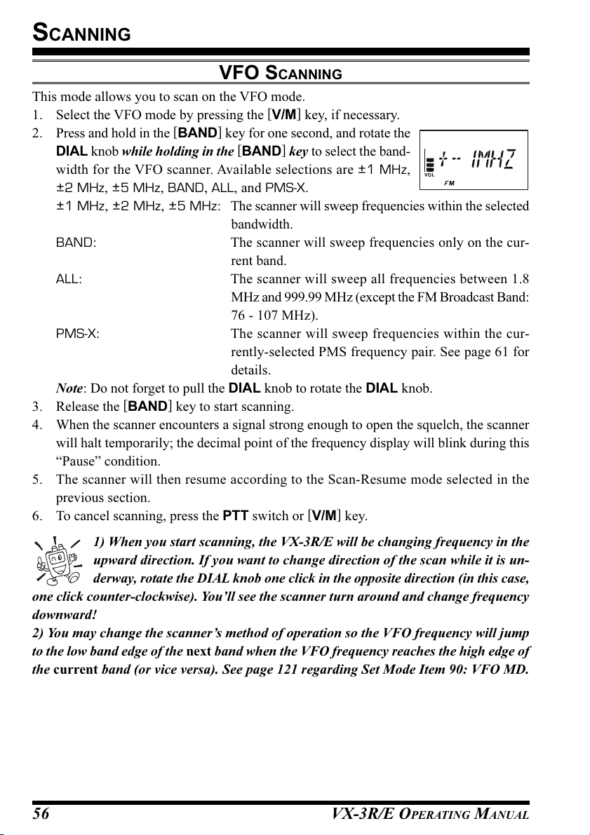
SCANNING
VFO SCANNING
This mode allows you to scan on the VFO mode.
1. Select the VFO mode by pressing the [V/M] key, if necessary.
2. Press and hold in the [BAND] key for one second, and rotate the
DIAL knob while holding in the [BAND] key to select the band-
width for the VFO scanner. Available selections are ±1 MHz,
±2 MHz, ±5 MHz, BAND, ALL, and PMS-X.
±1 MHz, ±2 MHz, ±5 MHz: The scanner will sweep frequencies within the selected
bandwidth.
BAND: The scanner will sweep frequencies only on the cur-
rent band.
ALL: The scanner will sweep all frequencies between 1.8
MHz and 999.99 MHz (except the FM Broadcast Band:
76 - 107 MHz).
PMS-X: The scanner will sweep frequencies within the cur-
rently-selected PMS frequency pair. See page 61 for
details.
Note: Do not forget to pull the DIAL knob to rotate the DIAL knob.
3. Release the [BAND] key to start scanning.
4. When the scanner encounters a signal strong enough to open the squelch, the scanner
will halt temporarily; the decimal point of the frequency display will blink during this
“Pause” condition.
5. The scanner will then resume according to the Scan-Resume mode selected in the
previous section.
6. To cancel scanning, press the PTT switch or [V/M] key.
1) When you start scanning, the VX-3R/E will be changing frequency in the
upward direction. If you want to change direction of the scan while it is un-
derway, rotate the DIAL knob one click in the opposite direction (in this case,
one click counter-clockwise). You’ll see the scanner turn around and change frequency
downward!
2) You may change the scanner’s method of operation so the VFO frequency will jump
to the low band edge of the next band when the VFO frequency reaches the high edge of
the current band (or vice versa). See page 121 regarding Set Mode Item 90: VFO MD.
VX-3R/E OPERATING MANUAL56

SCANNING
VFO SCANNING
HOW TO SKIP (OMIT) A FREQUENCY DURING VFO SCAN
If the VFO scan stops on a frequency or frequencies that you do not need (such as a spuri-
ous radiation from a television), such frequencies can be “skipped” during VFO scanning.
A special “Frequency Skip Memory” bank is reserved to store these frequencies.
To skip a frequency during VFO scanning:
1. While VFO scanning is stopped on the frequency that you do not need, press and hold
the [F/W] key for 1/2 seconds, then rotate the DIAL knob to select the desired Fre-
quency Skip Memory channel (901 - 999). The microprocessor will automatically
select the next-available “free” Frequency Skip Memory channel (a memory register
on which no data has been stored). If you see that any blinking channel number, it
means that the channel currently has no data written on it (i.e. the channel is “free”).
Note: Do not forget to pull the DIAL knob to rotate the DIAL knob.
2. Press the [F/W] key to store the frequency into the Frequency Skip Memory. It will
now be ignored during VFO scanning.
To re-institute a frequency into the VFO scan loop:
1. Press the [V/M] key, if needed, to enter the MR mode.
2. Press and hold in the [F/W] key for 1/2 second, then rotate the DIAL knob to select the
memory channel to be re-instituted.
Note: Do not forget to pull the DIAL knob to rotate the DIAL knob.
3. Press the
restore the frequency into the VFO scan loop.
[ ]
key to delete the channel from the Frequency Skip Memory; this will
The VX-3R/E has 99 VFO Frequency Skip Memory Channels.
SETTING THE SQUELCH LEVEL DURING ACTIVE SCANNING OPERATION
The VX-3R/E allows adjustment of the Squelch level “on the fly” while you are
scanning.
1. While the scanner is engaged, press the [F/W] key. Then press the [MONI
key (the current squelch level will appear in the Memory
Channel Number display slot in the frequency display).
2. Rotate the DIAL to select the desired Squelch level.
Note: Do not forget to pull the DIAL knob to rotate the
DIAL knob.
3. Press the PTT switch momentarily to save the new setting and exit to normal
operation. In this case, pressing the PTT switch this one time will not cause
scanning to stop.
]
VX-3R/E OPERATING MANUAL 57
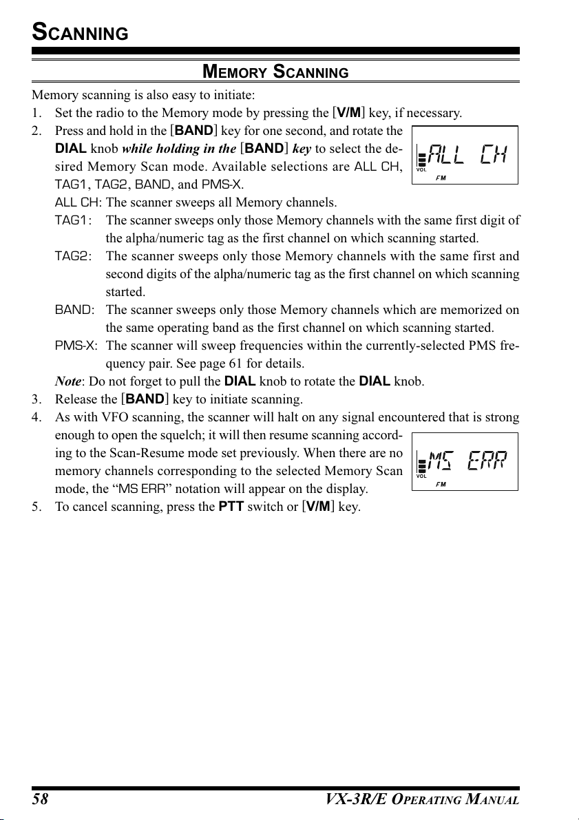
SCANNING
MEMORY SCANNING
Memory scanning is also easy to initiate:
1. Set the radio to the Memory mode by pressing the [V/M] key, if necessary.
2. Press and hold in the [BAND] key for one second, and rotate the
DIAL knob while holding in the [BAND] key to select the de-
sired Memory Scan mode. Available selections are ALL CH,
TAG1, TAG2, BAND, and PMS-X.
ALL CH: The scanner sweeps all Memory channels.
TAG1: The scanner sweeps only those Memory channels with the same first digit of
the alpha/numeric tag as the first channel on which scanning started.
TAG2: The scanner sweeps only those Memory channels with the same first and
second digits of the alpha/numeric tag as the first channel on which scanning
started.
BAND: The scanner sweeps only those Memory channels which are memorized on
the same operating band as the first channel on which scanning started.
PMS-X: The scanner will sweep frequencies within the currently-selected PMS fre-
quency pair. See page 61 for details.
Note: Do not forget to pull the DIAL knob to rotate the DIAL knob.
3. Release the [BAND] key to initiate scanning.
4. As with VFO scanning, the scanner will halt on any signal encountered that is strong
enough to open the squelch; it will then resume scanning accord-
ing to the Scan-Resume mode set previously. When there are no
memory channels corresponding to the selected Memory Scan
mode, the “MS ERR” notation will appear on the display.
5. To cancel scanning, press the PTT switch or [V/M] key.
VX-3R/E OPERATING MANUAL58
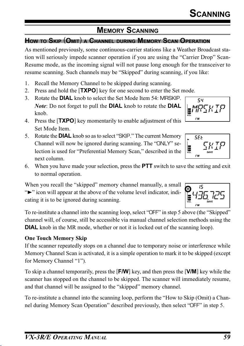
SCANNING
MEMORY SCANNING
HOW TO SKIP (OMIT) A CHANNEL DURING MEMORY SCAN OPERATION
As mentioned previously, some continuous-carrier stations like a Weather Broadcast sta-
tion will seriously impede scanner operation if you are using the “Carrier Drop” Scan-
Resume mode, as the incoming signal will not pause long enough for the transceiver to
resume scanning. Such channels may be “Skipped” during scanning, if you like:
1. Recall the Memory Channel to be skipped during scanning.
2. Press and hold the [TXPO] key for one second to enter the Set mode.
3. Rotate the DIAL knob to select the Set Mode Item 54: MRSKIP.
Note: Do not forget to pull the DIAL knob to rotate the DIAL
knob.
4. Press the [TXPO] key momentarily to enable adjustment of this
Set Mode Item.
5. Rotate the DIAL knob so as to select “SKIP.” The current Memory
Channel will now be ignored during scanning. The “ONLY” se-
lection is used for “Preferential Memory Scan,” described in the
next column.
6. When you have made your selection, press the PTT switch to save the setting and exit
to normal operation.
When you recall the “skipped” memory channel manually, a small
“” icon will appear at the above of the volume level indicator, indi-
cating it is to be ignored during scanning.
To re-institute a channel into the scanning loop, select “OFF” in step 5 above (the “Skipped”
channel will, of course, still be accessible via manual channel selection methods using the
DIAL knob in the MR mode, whether or not it is locked out of the scanning loop).
One Touch Memory Skip
If the scanner repeatedly stops on a channel due to temporary noise or interference while
Memory Channel Scan is activated, it is a simple operation to mark it to be skipped (except
for Memory Channel “1”).
To skip a channel temporarily, press the [F/W] key, and then press the [V/M] key while the
scanner has stopped on the channel to be skipped. The scanner will immediately resume,
and that channel will be assigned to the “skipped” memory channel.
To re-institute a channel into the scanning loop, perform the “How to Skip (Omit) a Chan-
nel during Memory Scan Operation” described previously, then select “OFF” in step 5.
VX-3R/E OPERATING MANUAL 59
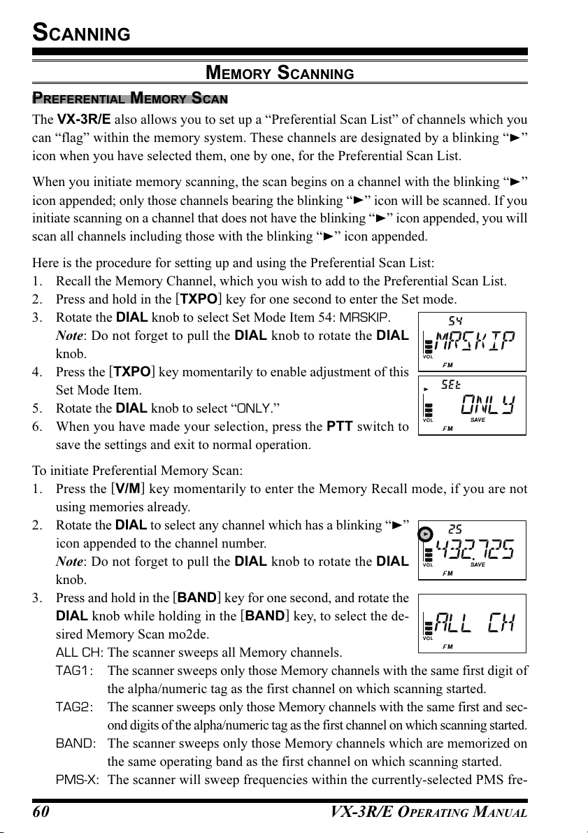
SCANNING
MEMORY SCANNING
PREFERENTIAL MEMORY SCAN
The VX-3R/E also allows you to set up a “Preferential Scan List” of channels which you
can “flag” within the memory system. These channels are designated by a blinking “”
icon when you have selected them, one by one, for the Preferential Scan List.
When you initiate memory scanning, the scan begins on a channel with the blinking “”
icon appended; only those channels bearing the blinking “” icon will be scanned. If you
initiate scanning on a channel that does not have the blinking “” icon appended, you will
scan all channels including those with the blinking “” icon appended.
Here is the procedure for setting up and using the Preferential Scan List:
1. Recall the Memory Channel, which you wish to add to the Preferential Scan List.
2. Press and hold in the [TXPO] key for one second to enter the Set mode.
3. Rotate the DIAL knob to select Set Mode Item 54: MRSKIP.
Note: Do not forget to pull the DIAL knob to rotate the DIAL
knob.
4. Press the [TXPO] key momentarily to enable adjustment of this
Set Mode Item.
5. Rotate the DIAL knob to select “ONLY.”
6. When you have made your selection, press the PTT switch to
save the settings and exit to normal operation.
To initiate Preferential Memory Scan:
1. Press the [V/M] key momentarily to enter the Memory Recall mode, if you are not
using memories already.
2. Rotate the DIAL to select any channel which has a blinking “”
icon appended to the channel number.
Note: Do not forget to pull the DIAL knob to rotate the DIAL
knob.
3. Press and hold in the [BAND] key for one second, and rotate the
DIAL knob while holding in the [BAND] key, to select the de-
sired Memory Scan mo2de.
ALL CH: The scanner sweeps all Memory channels.
TAG1: The scanner sweeps only those Memory channels with the same first digit of
the alpha/numeric tag as the first channel on which scanning started.
TAG2: The scanner sweeps only those Memory channels with the same first and sec-
ond digits of the alpha/numeric tag as the first channel on which scanning started.
BAND: The scanner sweeps only those Memory channels which are memorized on
the same operating band as the first channel on which scanning started.
PMS-X: The scanner will sweep frequencies within the currently-selected PMS fre-
VX-3R/E OPERATING MANUAL60
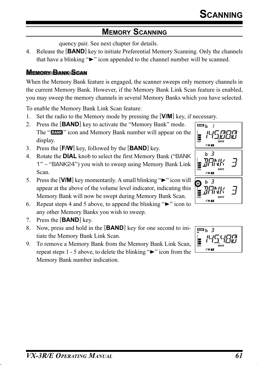
SCANNING
MEMORY SCANNING
quency pair. See next chapter for details.
4. Release the [BAND] key to initiate Preferential Memory Scanning. Only the channels
that have a blinking “” icon appended to the channel number will be scanned.
MEMORY BANK SCAN
When the Memory Bank feature is engaged, the scanner sweeps only memory channels in
the current Memory Bank. However, if the Memory Bank Link Scan feature is enabled,
you may sweep the memory channels in several Memory Banks which you have selected.
To enable the Memory Bank Link Scan feature:
1. Set the radio to the Memory mode by pressing the [V/M] key, if necessary.
2. Press the [BAND] key to activate the “Memory Bank” mode.
The “ ” icon and Memory Bank number will appear on the
display.
3. Press the [F/W] key, followed by the [BAND] key.
4. Rotate the DIAL knob to select the first Memory Bank (“BANK
1” ~ “BANK24”) you wish to sweep using Memory Bank Link
Scan.
5. Press the [V/M] key momentarily. A small blinking “” icon will
appear at the above of the volume level indicator, indicating this
Memory Bank will now be swept during Memory Bank Scan.
6. Repeat steps 4 and 5 above, to append the blinking “” icon to
any other Memory Banks you wish to sweep.
7. Press the [BAND] key.
8. Now, press and hold in the [BAND] key for one second to ini-
tiate the Memory Bank Link Scan.
9. To remove a Memory Bank from the Memory Bank Link Scan,
repeat steps 1 - 5 above, to delete the blinking “” icon from the
Memory Bank number indication.
VX-3R/E OPERATING MANUAL 61

SCANNING
)
PROGRAMMABLE (BAND LIMIT
This feature allows you to set sub-band limits for either scanning or manual VFO opera-
tion. For example, you might wish to set up a limit (in North America) of 144.300 MHz to
148.000 MHz, to prevent encroachment into the SSB/CW “Weak Signal” portion of the
band below 144.300 MHz. Here’s how to do this:
1. Set the radio to the VFO mode by pressing the [V/M] key, if necessary.
2. Using the techniques learned earlier in the above procedures, store 144.300 MHz into
Memory Channel #L1 (the “L” designates the Lower sub-band limit).
3. Likewise, store 148.000 MHz into Memory Channel #U1 (the “U” designates the
Upper sub-band limit).
4. Set the radio to the Memory mode by pressing the [V/M] key.
5. Press and hold in the [BAND] key for one second and rotate the
DIAL knob while holding in the [BAND] key to select the de-
sired PMS frequency pair (PMSxx). Then release the [BAND
key to initiate the Programmable (Band Limit) Memory Scan.
The Memory Channel number will be replaced by “Pxx”. Tuning
and scanning will now be limited within the just-programmed
range.
Note: Do not forget to pull the DIAL knob to rotate the DIAL knob.
6. 50 pairs of Band Limit memories, labeled L1/U1 through L50/U50 are available. You
therefore can set upper and lower operation limits on a number of bands, if you like.
M
EMORY SCAN
(
]
PMS
)
VX-3R/E OPERATING MANUAL62
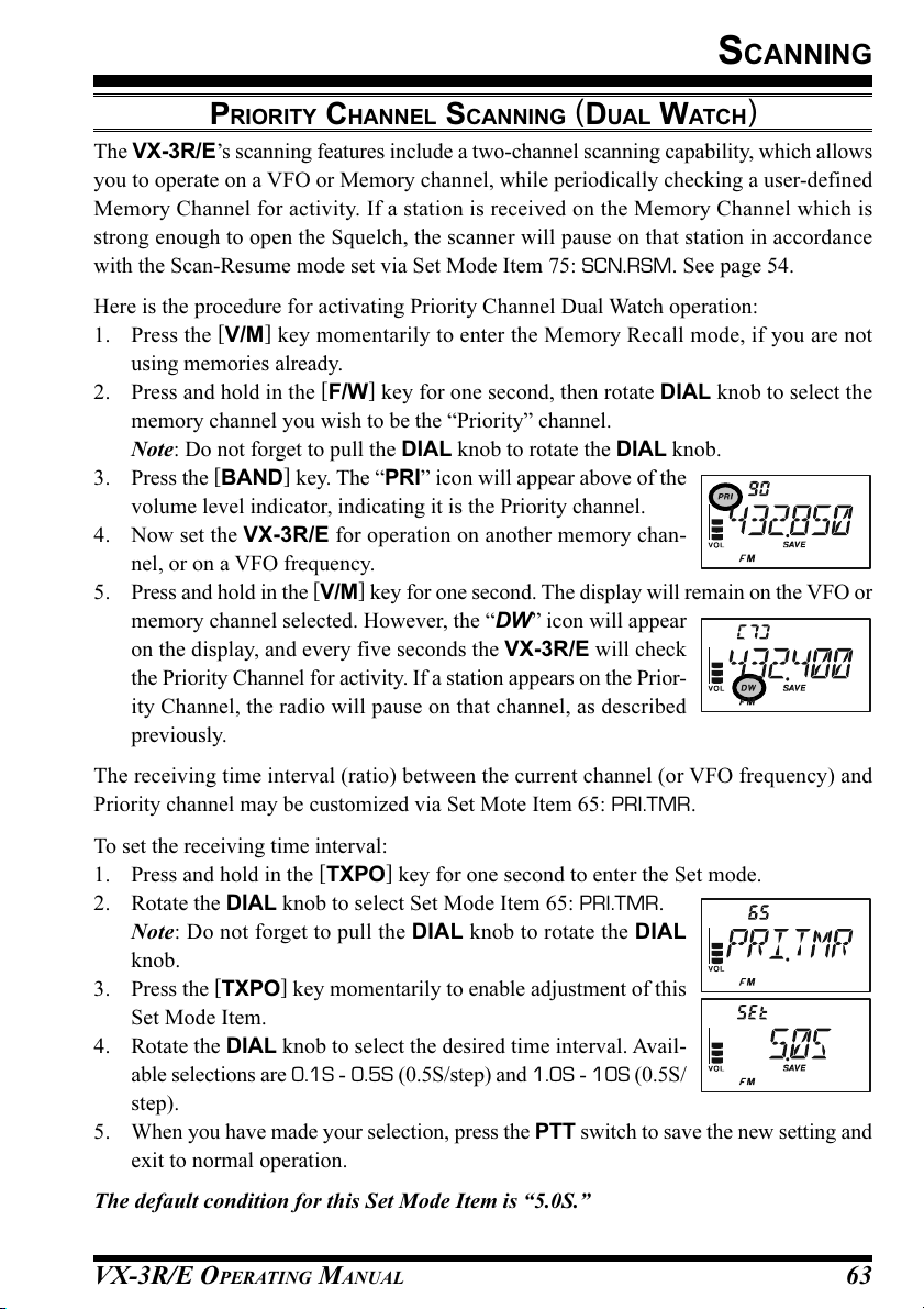
SCANNING
PRIORITY CHANNEL SCANNING (DUAL WATCH
The VX-3R/E’s scanning features include a two-channel scanning capability, which allows
you to operate on a VFO or Memory channel, while periodically checking a user-defined
Memory Channel for activity. If a station is received on the Memory Channel which is
strong enough to open the Squelch, the scanner will pause on that station in accordance
with the Scan-Resume mode set via Set Mode Item 75: SCN.RSM. See page 54.
Here is the procedure for activating Priority Channel Dual Watch operation:
1. Press the [V/M] key momentarily to enter the Memory Recall mode, if you are not
using memories already.
2. Press and hold in the [F/W] key for one second, then rotate DIAL knob to select the
memory channel you wish to be the “Priority” channel.
Note: Do not forget to pull the DIAL knob to rotate the DIAL knob.
3. Press the [BAND] key. The “PRI” icon will appear above of the
volume level indicator, indicating it is the Priority channel.
4. Now set the VX-3R/E for operation on another memory chan-
nel, or on a VFO frequency.
5. Press and hold in the [V/M] key for one second. The display will remain on the VFO or
memory channel selected. However, the “DW” icon will appear
on the display, and every five seconds the VX-3R/E will check
the Priority Channel for activity. If a station appears on the Prior-
ity Channel, the radio will pause on that channel, as described
previously.
)
The receiving time interval (ratio) between the current channel (or VFO frequency) and
Priority channel may be customized via Set Mote Item 65: PRI.TMR.
To set the receiving time interval:
1. Press and hold in the [TXPO] key for one second to enter the Set mode.
2. Rotate the DIAL knob to select Set Mode Item 65: PRI.TMR.
Note: Do not forget to pull the DIAL knob to rotate the DIAL
knob.
3. Press the [TXPO] key momentarily to enable adjustment of this
Set Mode Item.
4. Rotate the DIAL knob to select the desired time interval. Avail-
able selections are 0.1S - 0.5S (0.5S/step) and 1.0S - 10S (0.5S/
step).
5. When you have made your selection, press the PTT switch to save the new setting and
exit to normal operation.
The default condition for this Set Mode Item is “5.0S.”
VX-3R/E OPERATING MANUAL 63

SCANNING
PRIORITY CHANNEL SCANNING (DUAL WATCH
)
PRIORITY REVERT MODE
During Priority channel operation (Dual Watch), a special feature is available which will
allow you to move to the Priority Channel instantly, without waiting for activity to appear
on the Priority Channel.
When this feature is enabled, and priority monitoring is engaged, just press the microphone’s
PTT switch. Operation will instantly revert to the Priority Channel.
To enable Priority Revert operation:
1. Press and hold in the [TXPO] key for one second to enter the Set mode.
2. Rotate the DIAL knob to select Set Mode Item 64: PRI.RVT.
Note: Do not forget to pull the DIAL knob to rotate the DIAL
knob.
3. Press the [TXPO] key momentarily to enable adjustment of this
Set Mode Item.
4. Rotate the DIAL knob so as to select “ON.”
5. When you have made your selection, press the PTT switch to
save the settings and exit to normal operation.
To disable Priority Revert operation, select “OFF” in step 4 above.
VX-3R/E OPERATING MANUAL64

SCANNING
AUTOMATIC LAMP ILLUMINATION ON SCAN STOP
The VX-3R/E will automatically illuminate the LCD Lamp whenever the scanner stops on
a signal; this allows you to see the frequency of the incoming signal better at night. Note
that this will, of course, increase the battery consumption, so be sure to switch it off during
the day (the default condition for this feature is “ON”).
The procedure for disabling the Scan Lamp is:
1. Press and hold in the [TXPO] key for one second to enter the Set mode.
2. Rotate the DIAL knob to select Set Mode Item 74: SCN.LMP.
Note: Do not forget to pull the DIAL knob to rotate the DIAL
knob.
3. Press the [TXPO] key momentarily to enable adjustment of this
Set Mode Item.
4. Rotate the DIAL knob to set this Set Mode Item to “OFF.”
5. When you have made your selection, press the PTT switch to
save the setting and exit to normal operation.
BAND EDGE BEEPER
The VX-3R/E will automatically “beep” when a band edge is encountered during scanning
(either in standard VFO scanning or during PMS operation). You may enable this feature
(band edge beeper) when the frequency reaches the band edge while selecting the VFO
frequency by the DIAL knob.
The procedure for enabling the Band-Edge Beeper is:
1. Press and hold in the [TXPO] key for one second to enter the Set mode.
2. Rotate the DIAL knob to select Set Mode Item 12: BP EDG.
Note: Do not forget to pull the DIAL knob to rotate the DIAL
knob.
3. Press the [TXPO] key momentarily to enable adjustment of this
Set Mode Item.
4. Rotate the DIAL knob to set this Set Mode Item to “ON.”
5. When you have made your selection, press the PTT switch to
save the setting and exit to normal operation.
VX-3R/E OPERATING MANUAL 65
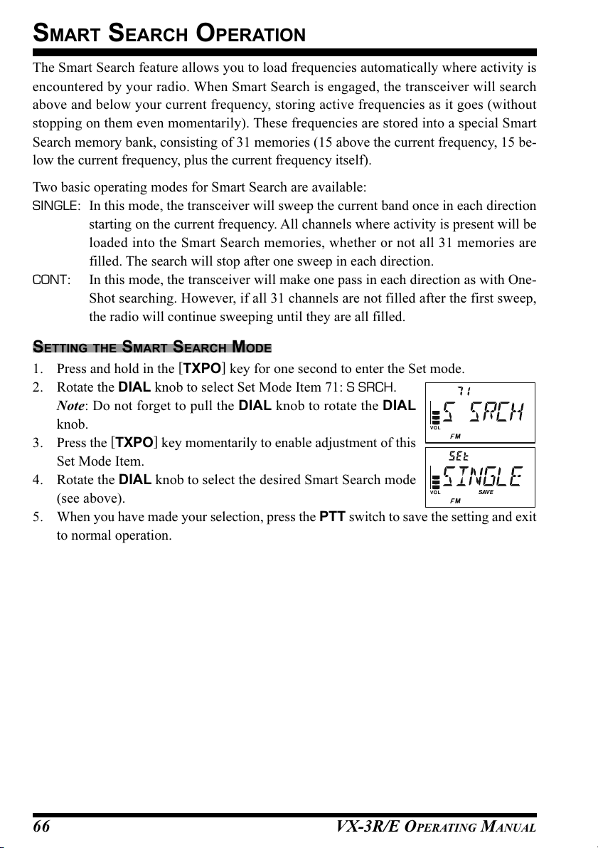
SMART SEARCH OPERATION
The Smart Search feature allows you to load frequencies automatically where activity is
encountered by your radio. When Smart Search is engaged, the transceiver will search
above and below your current frequency, storing active frequencies as it goes (without
stopping on them even momentarily). These frequencies are stored into a special Smart
Search memory bank, consisting of 31 memories (15 above the current frequency, 15 be-
low the current frequency, plus the current frequency itself).
Two basic operating modes for Smart Search are available:
SINGLE: In this mode, the transceiver will sweep the current band once in each direction
starting on the current frequency. All channels where activity is present will be
loaded into the Smart Search memories, whether or not all 31 memories are
filled. The search will stop after one sweep in each direction.
CONT: In this mode, the transceiver will make one pass in each direction as with One-
Shot searching. However, if all 31 channels are not filled after the first sweep,
the radio will continue sweeping until they are all filled.
SETTING THE SMART SEARCH MODE
1. Press and hold in the [TXPO] key for one second to enter the Set mode.
2. Rotate the DIAL knob to select Set Mode Item 71: S SRCH.
Note: Do not forget to pull the DIAL knob to rotate the DIAL
knob.
3. Press the [TXPO] key momentarily to enable adjustment of this
Set Mode Item.
4. Rotate the DIAL knob to select the desired Smart Search mode
(see above).
5. When you have made your selection, press the PTT switch to save the setting and exit
to normal operation.
VX-3R/E OPERATING MANUAL66

SMART SEARCH OPERATION
STORING SMART SEARCH MEMORIES
1. Set the radio to the VFO mode. Be sure that you have the Squelch
adjusted properly (so that band noise is quieted).
2. Rotate the DIAL, while pressing and holding in the [MODE
key, to select the “S SRCH (Smart Search) Mode.”
Note: Do not forget to pull the DIAL knob to rotate the DIAL
knob.
3. Release the [MODE] key to enter the Smart Search mode.
4. Press and hold the [BAND] key for one second to begin the Smart Search scanning.
5. As active channels are detected, you will observe the number of “loaded” channels
increasing in the regular memory channel window.
6. Depending on the mode you set for Smart Search operation
(“SINGLE” or “CONT”), the Smart Search scan will eventually
terminate, and the LCD will revert to Smart Search Memory
Channel “C.”
7. To recall the Smart Search memories, rotate the DIAL knob to choose from among the
Smart Search memories.
8. To return to normal operation, just press the [MODE] key.
Smart Search is a great tool when visiting a city for the first time. You don’t
need to spend hours looking up repeater frequencies from a reference
guidebook…just ask your VX-3R/E where the action is!
]
VX-3R/E OPERATING MANUAL 67

CHANNEL COUNTER OPERATION
The Channel Counter allows measuring of the frequency of a nearby transmitter, without
knowing that frequency in advance. The frequency can be measured by bringing the VX-
3R/E close to the transceiver which is transmitting.
The VX-3R/E performs a high-speed search within a ±5 MHz range from the frequency
displayed on the LCD. When the strongest signal in that range is identified, the VX-3R/E
displays the frequency of that (strongest) signal, and writes it into the special “Channel
Counter” memory.
Note: This Channel Counter is designed to provide an indication of the operating fre-
quency of the incoming signal, one that is close enough to allow the user, thereafter, to tune
precisely to the other station’s frequency. This feature is not, however, designed to provide
a precise determination of the other station’s frequency.
1. Set the radio to the VFO mode in the predicted frequency range
for the transmitter to be measured.
2. Bring the VX-3R/E into close proximity to the transmitter to be
measured.
3. Rotate the DIAL, while pressing and holding in the [MODE
key, to select the “CH CNT (Channel Counter) mode.”
Note: Do not forget to pull the DIAL knob to rotate the DIAL
knob.
4. Release the [MODE] key to begin the Channel Counter; the fre-
quency of the nearby station will be displayed. When the chan-
nel counter is active, a 50 dB receiver front-end attenuator will
be engaged. Therefore, only stations in close proximity may have
their frequencies measured using this feature.
5. If it isn’t possible to determine the signal’s frequency, the trans-
ceiver will return to the frequency on which you were operating
when you started Channel Counter operation.
6. When you are finished, just press the [MODE] key. The radio will exit from Channel
Counter operation.
]
VX-3R/E OPERATING MANUAL68
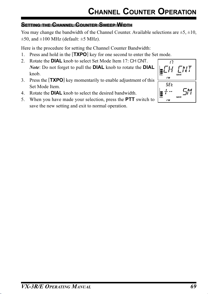
CHANNEL COUNTER OPERATION
SETTING THE CHANNEL COUNTER SWEEP WIDTH
You may change the bandwidth of the Channel Counter. Available selections are ±5, ±10,
±50, and ±100 MHz (default: ±5 MHz).
Here is the procedure for setting the Channel Counter Bandwidth:
1. Press and hold in the [TXPO] key for one second to enter the Set mode.
2. Rotate the DIAL knob to select Set Mode Item 17: CH CNT.
Note: Do not forget to pull the DIAL knob to rotate the DIAL
knob.
3. Press the [TXPO] key momentarily to enable adjustment of this
Set Mode Item.
4. Rotate the DIAL knob to select the desired bandwidth.
5. When you have made your selection, press the PTT switch to
save the new setting and exit to normal operation.
VX-3R/E OPERATING MANUAL 69

MESSAGE FEATURE
The VX-3R/E provides a message feature, which sends a message (up to 16 characters)
instead of sending a voice. 20 different messages can be programmed, and one of them can
be selected and transmitted with your ID.
Note
The Message Feature requires that all members (1) use the VX-3R/E, VX-
8R/DR/E/DE, VX-8GR/GE, or Vertex Standard FTM-10R/RS/E/SE trans-
ceiver, (2) store the same messages into the message slot, (3) store the same
member list into the member box, and (4) set the same frequency.
Does not send the Message through the repeater.
PROGRAMMING A MESSAGE
(Requires all members set the same message into the same message slot in the same order.)
The VX-3R/E has 20 message slots, including a factory-programmed message (EMER-
GENCY). The factory-programmed message of course can be overwritten at any time with
personalized messages.
1. Press and hold in the [TXPO] key for one second to enter the Set mode.
2. Rotate the DIAL knob to select Set Mode Item 57: MSG.SEL.
Note: Do not forget to pull the DIAL knob to rotate the DIAL
knob.
3. Press the [TXPO] key momentarily to enable adjustment of this
Set Mode Item.
4. Rotate the DIAL knob to select the desired Message slot into
which you wish to store a message. The LCD displays the previ-
ously stored message.
5. Press the [V/M] key momentarily to enable programming of the
message.
6. Press and hold in the [HM/RV] key for one second to clear the
previously stored message, if desired.
7. Rotate the DIAL knob to select the first character of the message
you wish to store, and then press the [V/M] key to save the first
character of the message and move on to the next place.
8. Repeat the previous step to complete the message (up to 16 char-
acters). If you make a mistake, press the [BAND] key to move
back to the incorrect character, then re-enter the correct character.
9. Press and hold in the [HM/RV] key for one second to delete all
data after the cursor that may have been previously stored erroneously.
10. When the Message entry is complete, press the [TXPO] key momentarily.
11. If you wish to store another message, repeat steps 3 through 10 above.
12. Press the PTT switch to exit to normal operation.
VX-3R/E OPERATING MANUAL70
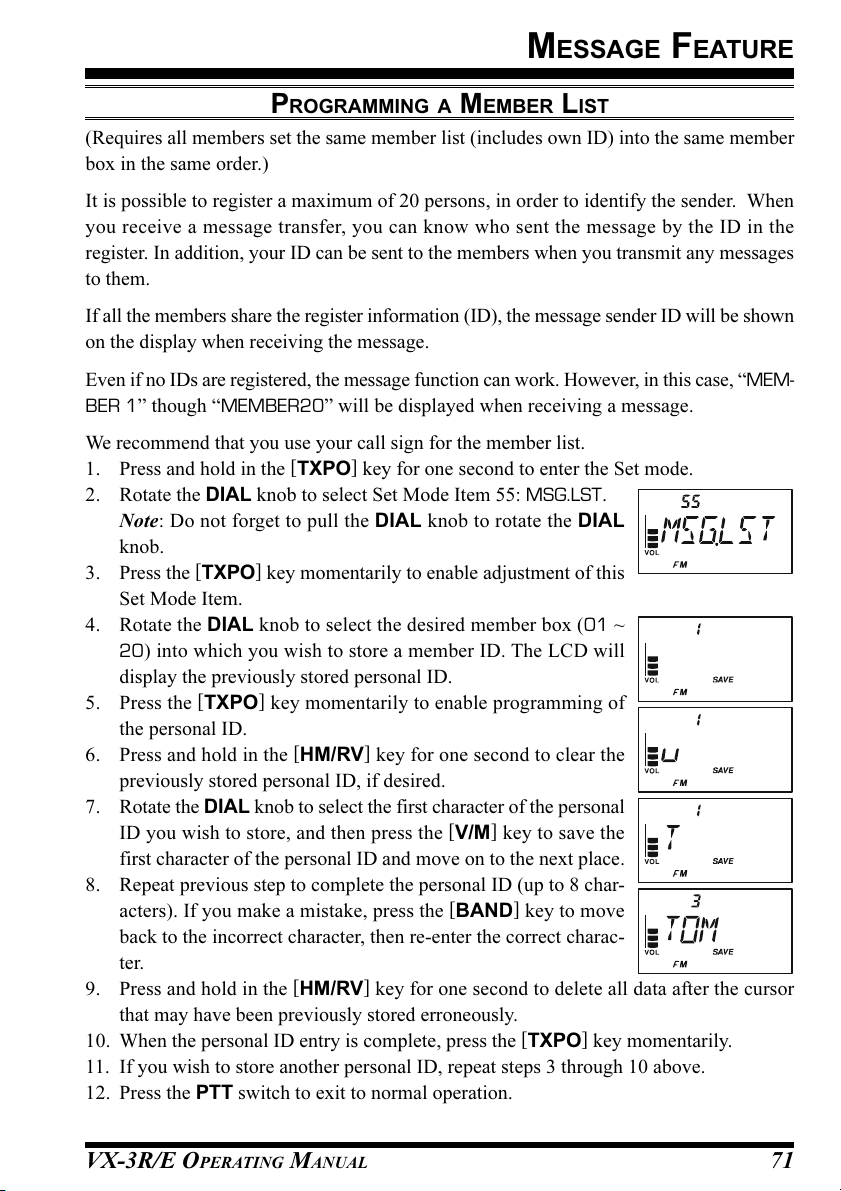
MESSAGE FEATURE
PROGRAMMING A MEMBER LIST
(Requires all members set the same member list (includes own ID) into the same member
box in the same order.)
It is possible to register a maximum of 20 persons, in order to identify the sender. When
you receive a message transfer, you can know who sent the message by the ID in the
register. In addition, your ID can be sent to the members when you transmit any messages
to them.
If all the members share the register information (ID), the message sender ID will be shown
on the display when receiving the message.
Even if no IDs are registered, the message function can work. However, in this case, “MEM-
BER 1” though “MEMBER20” will be displayed when receiving a message.
We recommend that you use your call sign for the member list.
1. Press and hold in the [TXPO] key for one second to enter the Set mode.
2. Rotate the DIAL knob to select Set Mode Item 55: MSG.LST.
Note: Do not forget to pull the DIAL knob to rotate the DIAL
knob.
3. Press the [TXPO] key momentarily to enable adjustment of this
Set Mode Item.
4. Rotate the DIAL knob to select the desired member box (01 ~
20) into which you wish to store a member ID. The LCD will
display the previously stored personal ID.
5. Press the [TXPO] key momentarily to enable programming of
the personal ID.
6. Press and hold in the [HM/RV] key for one second to clear the
previously stored personal ID, if desired.
7. Rotate the DIAL knob to select the first character of the personal
ID you wish to store, and then press the [V/M] key to save the
first character of the personal ID and move on to the next place.
8. Repeat previous step to complete the personal ID (up to 8 char-
acters). If you make a mistake, press the [BAND] key to move
back to the incorrect character, then re-enter the correct charac-
ter.
9. Press and hold in the [HM/RV] key for one second to delete all data after the cursor
that may have been previously stored erroneously.
10. When the personal ID entry is complete, press the [TXPO] key momentarily.
11. If you wish to store another personal ID, repeat steps 3 through 10 above.
12. Press the PTT switch to exit to normal operation.
VX-3R/E OPERATING MANUAL 71

MESSAGE FEATURE
SET YOUR PERSONAL ID
You choose your personal ID from the member list.
1. Press and hold in the [TXPO] key for one second to enter the Set mode.
2. Rotate the DIAL knob to select Set Mode Item 56: MSG.REG.
Note: Do not forget to pull the DIAL knob to rotate the DIAL knob.
3. Press the [TXPO] key momentarily to enable adjustment of this
Set Mode Item.
4. Rotate the DIAL knob to select the member box (1 ~ 20) where
your ID is stored.
5. Press the PTT switch to save the new setting and exit to normal
operation.
SENDING A MESSAGES
The registered message can be sent to the members who are receiving the coordination
frequency. When a message is sent, the transmitter’s ID will be sent also, and the receiver
can identify who sent the message.
The “Personal ID” setting (described previous paragraph) is required for the transmitter’s
ID to be shown with the received message.
1. Set the radio to the coordination frequency.
2. Press and hold in the [TXPO] key for one second to enter the Set mode.
3. Rotate the DIAL knob to select Set Mode Item 79: SQ TYP.
Note: Do not forget to pull the DIAL knob to rotate the DIAL knob.
4. Press the [TXPO] key momentarily to enable adjustment of this
Set Mode Item.
5. Rotate the DIAL knob to select “MESSAGE” (to activate the
Message feature).
6. Press the [TXPO] key momentarily, then rotate the DIAL knob
to select Set Mode Item 57: MEG.SEL.
7. Press the [TXPO] key momentarily to enable adjustment of this
Set Mode Item.
8. Rotate the DIAL to select the message you wish to send.
9. Press the PTT switch to exit from the Set Mode and activates the
Message feature.
10. When the Message feature is activated, the “M” notation will
appear at the 100 MHz digit of the frequency.
11. Press the PTT switch again (without speaking into the microphone)
to transmit the selected message on the coordination frequency. It
takes approximately 6 seconds to transmit the message.
VX-3R/E OPERATING MANUAL72

MESSAGE FEATURE
RECEIVING A MESSAGE
1. Set the radio to the coordination frequency.
2. Press and hold in the [TXPO] key for one second to enter the Set mode.
3. Rotate the DIAL knob to select Set Mode Item 79: SQ TYP.
Note: Do not forget to pull the DIAL knob to rotate the DIAL
knob.
4. Press the [TXPO] key momentarily to enable adjustment of this
Set Mode Item.
5. Rotate the DIAL knob to select “MESSAGE” (to activate the
Message feature).
6. Press the PTT switch to exit from the Set Mode and activates the
Message feature.
7. When you receive a message: a beep sounds, the TX/BUSY in-
dicator blinks white, and [“Message” FROM “sending station’s
ID”] scrolls on the display.
8. Press any key (except [VOL] key) to clear the received message, and wait for a new
message.
To disable the Message feature, repeat the above procedure, rotating the DIAL knob to
select “OFF” in step 5 above.
If you enable the CTCSS/DCS/EPCS Bell feature (described previously), you
can confirm that a message is coming in by a ringing “bell” sound alert.
VX-3R/E OPERATING MANUAL 73
EMERGENCY FEATURE
EMERGENCY CHANNEL OPERATION
The VX-3R/E includes an “Emergency” feature, which may be useful if you have someone
monitoring on the same frequency as your transceiver’s UHF “Home” channel. See page
44 for details on setting the Home channel.
The “Emergency” feature is activated by pressing and holding in the [HM/RV] key for one
second.
When this is done, (A) the radio is placed on the UHF amateur band Home channel, (B) it
emits a loud “Alarm” sound (the volume is controlled by rotating the DIAL knob while
pressing and holding the [VOL] key), (C) it flashes the TX/BUSY indicator in white, (D)
if you press the PTT switch, you will disable the Emergency feature temporarily. You can
then transmit on the UHF Home channel, and (E) two seconds after the PTT release, the
Emergency feature will resume.
To disable the “Emergency” feature, press and hold the [HM/RV] key for one second or
turn the radio Off by pressing and holding in the POWER switch for one second.
Use this feature if you are out for a walk and want a quick way of alerting a family member
to a dangerous situation. The alarm sound may discourage an attacker and allow you to
escape.
1) Be sure to arrange with a friend or family member to be monitoring on the
same frequency, as there will be no identification sent via the Emergency
alarm sound. And do not transmit the alarm tone except in a true emergency!
2) The TX/BUSY indicator may be changed to another function via Set Mode Item 32:
EMG.SEL; see page 112.
VX-3R/E OPERATING MANUAL74
EMERGENCY FEATURE
EMERGENCY AUTOMATIC ID (EAI) FEATURE
The Emergency Automatic ID (EAI) feature can be used to aid in searching for persons
who are incapacitated in disasters like earthquakes, especially search-and-rescue person-
nel who may have become injured in a debris field. When using the EAI feature, a searcher
transmits a unique command (CTCSS tone pair), which will automatically cause the in-
jured party’s radio to transmit, so others may perform direction-finding and effect a rescue.
The incapacitated party may not be able to speak or even press the PTT switch. The callsign
of the incapacitated person may also be transmitted, to assist the rescue team.
If an emergency group is working in a dangerous area, all members should engage the EAI
feature on their transceivers, so that others can assist a fallen team member, if necessary.
The Emergency Automatic ID (EAI) Feature has two operating modes: (1) Interval mode
and (2) Continuous mode.
In the Interval mode (when the VX-3R/E receives the CTCSS tone pair), the radio will
transmit a loud (0.5 second) beep every 2.5 seconds until the EAI timer expires.
In the continuous mode, the radio will automatically transmit a continuous signal (with
maximum microphone gain), until the EAI timer expires.
The EIA is activated when the CTCSS tone pair stored in the Receiving Pager Code Memory
(configured via Set Mode Item 61: PAG.CDR) is received for 5 seconds on the frequency,
which is stored in Memory Channel “EAI”. It is NOT necessary for the incapacitated per-
son to press the PTT switch.
A call sign may be stored in the radio and the CW identifier enabled via Set Mode Item 21:
CW ID. Then, when the EAI feature is activated in the Interval mode, the radio will trans-
mit the callsign once each minute. In addition, the bright LED will blink the call sign in
Morse code. The “callsign” ID can be changed to any desired sequence up to 16 charac-
ters, such as a name. The radio will transmit a loud (0.5 second) beep every 2.5 seconds,
and send the call sign each minute, until the EAI timer expires.
The Emergency Automatic ID (EAI) Feature requires that you:
(1) Store the CTCSS Tone Pair into the Receiving Pager Memory (see page 34 for the
procedure),
(2) Store the desired UHF coordination frequency into Memory Channel “EAI” (see page
42 for procedure). (We suggest using a frequency different from your normal operat-
ing channel.)
(3) Activate the EAI function “Set Mode Item 30: EIA” to “ON”.
The VX-3R/E radio may now be used normally. The EIA function will monitor the EIA
memory channel in the background, and it will be activated when the Pager Memory Tone
Pair is received on the EIA memory channel.
VX-3R/E OPERATING MANUAL 75
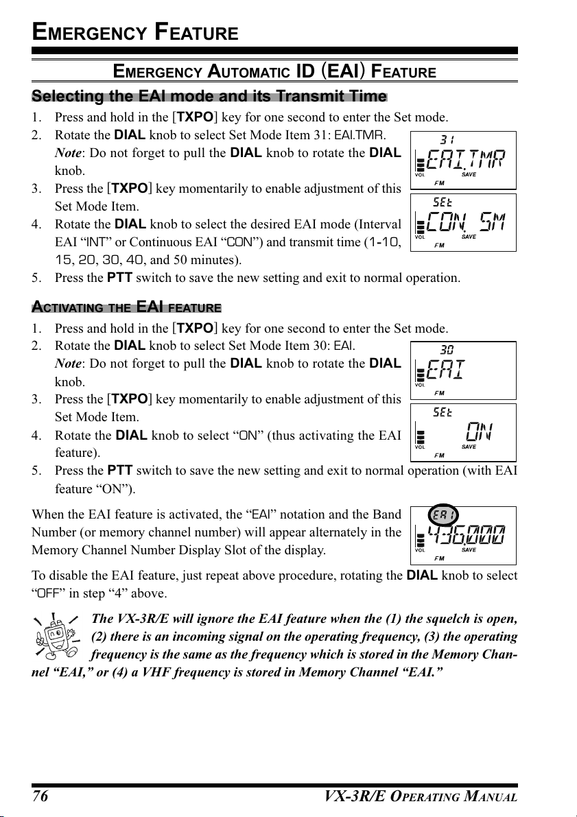
EMERGENCY FEATURE
EMERGENCY AUTOMATIC ID (EAI) FEATURE
Selecting the EAI mode and its Transmit Time
1. Press and hold in the [TXPO] key for one second to enter the Set mode.
2. Rotate the DIAL knob to select Set Mode Item 31: EAI.TMR.
Note: Do not forget to pull the DIAL knob to rotate the DIAL
knob.
3. Press the [TXPO] key momentarily to enable adjustment of this
Set Mode Item.
4. Rotate the DIAL knob to select the desired EAI mode (Interval
EAI “INT” or Continuous EAI “CON”) and transmit time (1-10,
15, 20, 30, 40, and 50 minutes).
5. Press the PTT switch to save the new setting and exit to normal operation.
ACTIVATING THE EAI FEATURE
1. Press and hold in the [TXPO] key for one second to enter the Set mode.
2. Rotate the DIAL knob to select Set Mode Item 30: EAI.
Note: Do not forget to pull the DIAL knob to rotate the DIAL
knob.
3. Press the [TXPO] key momentarily to enable adjustment of this
Set Mode Item.
4. Rotate the DIAL knob to select “ON” (thus activating the EAI
feature).
5. Press the PTT switch to save the new setting and exit to normal operation (with EAI
feature “ON”).
When the EAI feature is activated, the “EAI” notation and the Band
Number (or memory channel number) will appear alternately in the
Memory Channel Number Display Slot of the display.
To disable the EAI feature, just repeat above procedure, rotating the DIAL knob to select
“OFF” in step “4” above.
The VX-3R/E will ignore the EAI feature when the (1) the squelch is open,
(2) there is an incoming signal on the operating frequency, (3) the operating
frequency is the same as the frequency which is stored in the Memory Chan-
nel “EAI,” or (4) a VHF frequency is stored in Memory Channel “EAI.”
VX-3R/E OPERATING MANUAL76
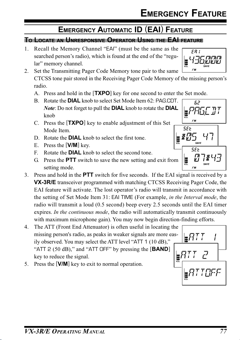
EMERGENCY FEATURE
EMERGENCY AUTOMATIC ID (EAI) FEATURE
TO LOCATE AN UNRESPONSIVE OPERATOR USING THE EAI FEATURE
1. Recall the Memory Channel “EAI” (must be the same as the
searched person’s radio), which is found at the end of the “regu-
lar” memory channel.
2. Set the Transmitting Pager Code Memory tone pair to the same
CTCSS tone pair stored in the Receiving Pager Code Memory of the missing person’s
radio.
A. Press and hold in the [TXPO] key for one second to enter the Set mode.
B. Rotate the DIAL knob to select Set Mode Item 62: PAG.CDT.
Note: Do not forget to pull the DIAL knob to rotate the DIAL
knob
C. Press the [TXPO] key to enable adjustment of this Set
Mode Item.
D. Rotate the DIAL knob to select the first tone.
E. Press the [V/M] key.
F. Rotate the DIAL knob to select the second tone.
G. Press the PTT switch to save the new setting and exit from
setting mode.
3. Press and hold in the PTT switch for five seconds. If the EAI signal is received by a
VX-3R/E transceiver programmed with matching CTCSS Receiving Pager Code, the
EAI feature will activate. The lost operator’s radio will transmit in accordance with
the setting of Set Mode Item 31: EAI TIME (For example, in the Interval mode, the
radio will transmit a loud (0.5 second) beep every 2.5 seconds until the EAI timer
expires. In the continuous mode, the radio will automatically transmit continuously
with maximum microphone gain). You may now begin direction-finding efforts.
4. The ATT (Front End Attenuator) is often useful in locating the
missing person's radio, as peaks in weaker signals are more eas-
ily observed. You may select the ATT level “ATT 1 (10 dB),”
“ATT 2 (50 dB),” and “ATT OFF” by pressing the [BAND
key to reduce the signal.
5. Press the [V/M] key to exit to normal operation.
]
VX-3R/E OPERATING MANUAL 77
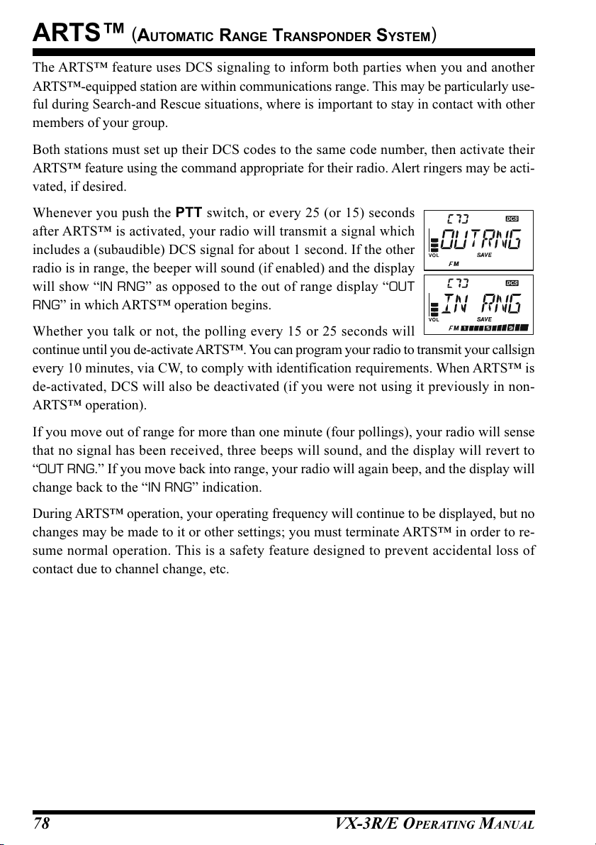
ARTS™
The ARTS™ feature uses DCS signaling to inform both parties when you and another
ARTS™-equipped station are within communications range. This may be particularly use-
ful during Search-and Rescue situations, where is important to stay in contact with other
members of your group.
Both stations must set up their DCS codes to the same code number, then activate their
ARTS™ feature using the command appropriate for their radio. Alert ringers may be acti-
vated, if desired.
Whenever you push the PTT switch, or every 25 (or 15) seconds
after ARTS™ is activated, your radio will transmit a signal which
includes a (subaudible) DCS signal for about 1 second. If the other
radio is in range, the beeper will sound (if enabled) and the display
will show “IN RNG” as opposed to the out of range display “OUT
RNG” in which ARTS™ operation begins.
Whether you talk or not, the polling every 15 or 25 seconds will
continue until you de-activate ARTS™. You can program your radio to transmit your callsign
every 10 minutes, via CW, to comply with identification requirements. When ARTS™ is
de-activated, DCS will also be deactivated (if you were not using it previously in non-
ARTS™ operation).
If you move out of range for more than one minute (four pollings), your radio will sense
that no signal has been received, three beeps will sound, and the display will revert to
“OUT RNG.” If you move back into range, your radio will again beep, and the display will
change back to the “IN RNG” indication.
(
AUTOMATIC RANGE TRANSPONDER SYSTEM
)
During ARTS™ operation, your operating frequency will continue to be displayed, but no
changes may be made to it or other settings; you must terminate ARTS™ in order to re-
sume normal operation. This is a safety feature designed to prevent accidental loss of
contact due to channel change, etc.
VX-3R/E OPERATING MANUAL78

ARTS™
(
AUTOMATIC RANGE TRANSPONDER SYSTEM
BASIC ARTS™ SETUP AND OPERATION
1. Set both radios to the same DCS code number, per the discussion on page 30.
2. Press and hold in the
the “OUT RNG” display on the LCD below the operating fre-
quency. ARTS™ operation has now commenced.
3. Every 25 seconds, your radio will transmit a “polling” call to the
other station. When that station responds with its own ARTS™
polling signal, the display will change to “IN RNG” to confirm
that the other station’s polling code was received in response to
yours.
4. Press and hold in the
normal functioning of the transceiver.
[ ]
key for one second. You will observe
[ ]
key for one second to exit ARTS™ operation and resume
ARTS™ POLLING TIME OPTIONS
The ARTS™ feature may be programmed to poll every 25 seconds (default value) or 15
seconds. The default value provides maximum battery conservation, because the polling
signal is sent out less frequently. To change the polling interval:
1. Press and hold in the [TXPO] key for one second to enter the Set mode.
2. Rotate the DIAL knob to select Set Mode Item 7: ARTSIT.
Note: Do not forget to pull the DIAL knob to rotate the DIAL
knob.
3. Press the [TXPO] key momentarily to enable adjustment of this
Set Mode Item.
4. Rotate the DIAL knob to select the desired polling interval (15
or 25 seconds).
5. When you have made your selection, press the PTT switch to
save the new setting and exit to normal operation.
)
VX-3R/E OPERATING MANUAL 79

ARTS™
(
AUTOMATIC RANGE TRANSPONDER SYSTEM
)
ARTS™ ALERT BEEP OPTIONS
The ARTS™ feature allows two kinds of alert beeps (or off), to alert you to the status of
ARTS™ operation. Depending on your location and the potential annoyance associated
with frequent beeps, you may choose the Beep mode which best suits your needs. The
choices are:
IN RANG: The beeps are issued only when the radio first confirms that you are within
range, but does not re-confirm with beeps thereafter.
ALWAYS: Every time a polling transmission is received from the other station, the alert
beeps will be heard.
OFF: No alert beeps will be heard. You must look at the display to confirm current
ARTS™ status.
To set the ARTS™ Beep mode, use the following procedure:
1. Press and hold in the [TXPO] key for one second to enter the Set mode.
2. Rotate the DIAL knob to select Set Mode Item 6: ARTSBP.
Note: Do not forget to pull the DIAL knob to rotate the DIAL
knob.
3. Press the [TXPO] key momentarily to enable adjustment of this
Set Mode Item.
4. Rotate the DIAL knob to select the desired ARTS™ Beep mode
(see above).
5. When you have made your selection, press the PTT switch to
save the new setting and exit to normal operation.
VX-3R/E OPERATING MANUAL80
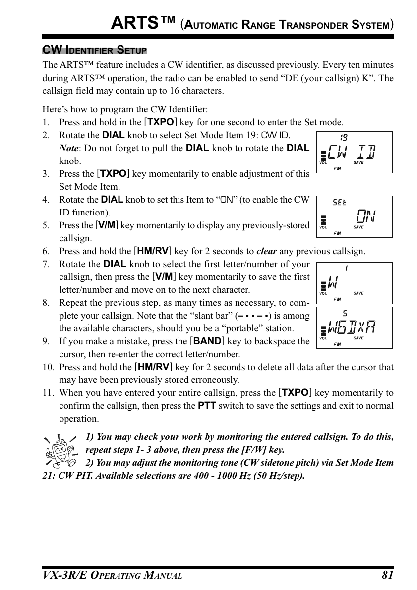
ARTS™
(
AUTOMATIC RANGE TRANSPONDER SYSTEM
CW IDENTIFIER SETUP
The ARTS™ feature includes a CW identifier, as discussed previously. Every ten minutes
during ARTS™ operation, the radio can be enabled to send “DE (your callsign) K”. The
callsign field may contain up to 16 characters.
Here’s how to program the CW Identifier:
1. Press and hold in the [TXPO] key for one second to enter the Set mode.
2. Rotate the DIAL knob to select Set Mode Item 19: CW ID.
Note: Do not forget to pull the DIAL knob to rotate the DIAL
knob.
3. Press the [TXPO] key momentarily to enable adjustment of this
Set Mode Item.
4. Rotate the DIAL knob to set this Item to “ON” (to enable the CW
ID function).
5. Press the [V/M] key momentarily to display any previously-stored
callsign.
6. Press and hold the [HM/RV] key for 2 seconds to clear any previous callsign.
7. Rotate the DIAL knob to select the first letter/number of your
callsign, then press the [V/M] key momentarily to save the first
letter/number and move on to the next character.
8. Repeat the previous step, as many times as necessary, to com-
plete your callsign. Note that the “slant bar” (–
the available characters, should you be a “portable” station.
9. If you make a mistake, press the [BAND] key to backspace the
cursor, then re-enter the correct letter/number.
10. Press and hold the [HM/RV] key for 2 seconds to delete all data after the cursor that
may have been previously stored erroneously.
11. When you have entered your entire callsign, press the [TXPO] key momentarily to
confirm the callsign, then press the PTT switch to save the settings and exit to normal
operation.
– •) is among
• •
)
1) You may check your work by monitoring the entered callsign. To do this,
repeat steps 1- 3 above, then press the [F/W] key.
2) You may adjust the monitoring tone (CW sidetone pitch) via Set Mode Item
21: CW PIT. Available selections are 400 - 1000 Hz (50 Hz/step).
VX-3R/E OPERATING MANUAL 81
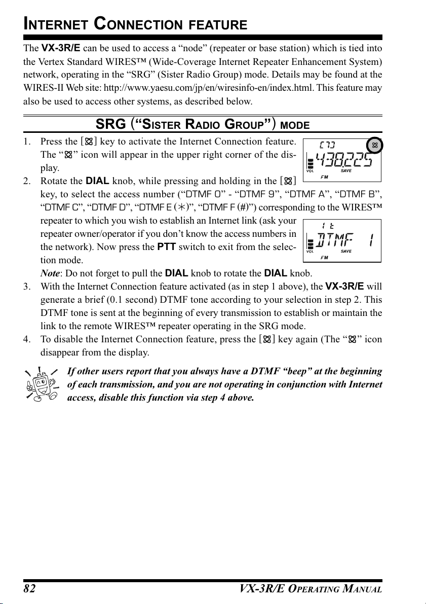
INTERNET CONNECTION FEATURE
The VX-3R/E can be used to access a “node” (repeater or base station) which is tied into
the Vertex Standard WIRES™ (Wide-Coverage Internet Repeater Enhancement System)
network, operating in the “SRG” (Sister Radio Group) mode. Details may be found at the
WIRES-II Web site: http://www.yaesu.com/jp/en/wiresinfo-en/index.html. This feature may
also be used to access other systems, as described below.
SRG (“SISTER RADIO GROUP”) MODE
1. Press the
The “ ” icon will appear in the upper right corner of the dis-
play.
2. Rotate the DIAL knob, while pressing and holding in the
key, to select the access number (“DTMF 0” - “DTMF 9”, “DTMF A”, “DTMF B”,
“DTMF C”, “DTMF D”, “DTMF E ()”, “DTMF F (#)”) corresponding to the WIRES™
repeater to which you wish to establish an Internet link (ask your
repeater owner/operator if you don’t know the access numbers in
the network). Now press the PTT switch to exit from the selec-
tion mode.
Note: Do not forget to pull the DIAL knob to rotate the DIAL knob.
3. With the Internet Connection feature activated (as in step 1 above), the VX-3R/E will
generate a brief (0.1 second) DTMF tone according to your selection in step 2. This
DTMF tone is sent at the beginning of every transmission to establish or maintain the
link to the remote WIRES™ repeater operating in the SRG mode.
4. To disable the Internet Connection feature, press the
disappear from the display.
[ ]
key to activate the Internet Connection feature.
[ ]
[ ]
key again (The “ ” icon
If other users report that you always have a DTMF “beep” at the beginning
of each transmission, and you are not operating in conjunction with Internet
access, disable this function via step 4 above.
VX-3R/E OPERATING MANUAL82
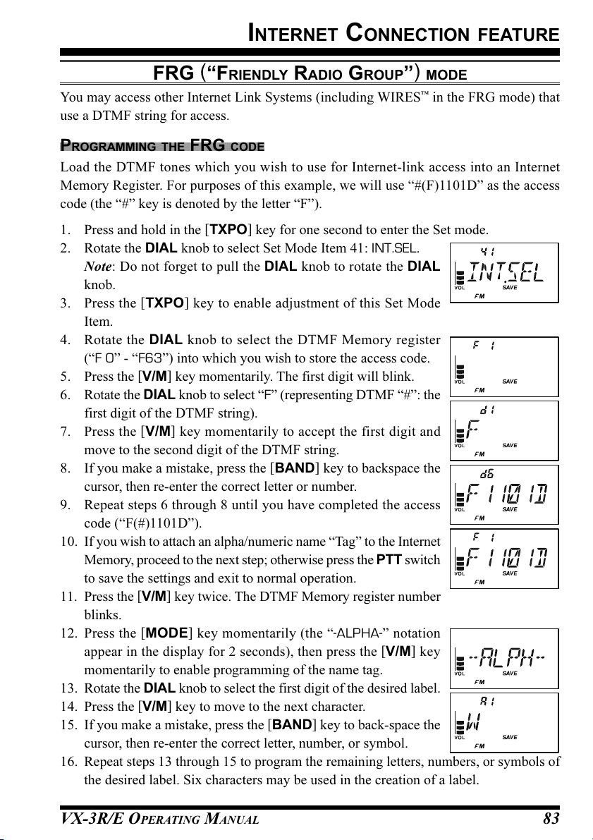
INTERNET CONNECTION FEATURE
FRG (“FRIENDLY RADIO GROUP”) MODE
You may access other Internet Link Systems (including WIRES™ in the FRG mode) that
use a DTMF string for access.
PROGRAMMING THE FRG CODE
Load the DTMF tones which you wish to use for Internet-link access into an Internet
Memory Register. For purposes of this example, we will use “#(F)1101D” as the access
code (the “#” key is denoted by the letter “F”).
1. Press and hold in the [TXPO] key for one second to enter the Set mode.
2. Rotate the DIAL knob to select Set Mode Item 41: INT.SEL.
Note: Do not forget to pull the DIAL knob to rotate the DIAL
knob.
3. Press the [TXPO] key to enable adjustment of this Set Mode
Item.
4. Rotate the DIAL knob to select the DTMF Memory register
(“F 0” - “F63”) into which you wish to store the access code.
5. Press the [V/M] key momentarily. The first digit will blink.
6. Rotate the DIAL knob to select “F” (representing DTMF “#”: the
first digit of the DTMF string).
7. Press the [V/M] key momentarily to accept the first digit and
move to the second digit of the DTMF string.
8. If you make a mistake, press the [BAND] key to backspace the
cursor, then re-enter the correct letter or number.
9. Repeat steps 6 through 8 until you have completed the access
code (“F(#)1101D”).
10. If you wish to attach an alpha/numeric name “Tag” to the Internet
Memory, proceed to the next step; otherwise press the PTT switch
to save the settings and exit to normal operation.
11. Press the [V/M] key twice. The DTMF Memory register number
blinks.
12. Press the [MODE] key momentarily (the “-ALPHA-” notation
appear in the display for 2 seconds), then press the [V/M] key
momentarily to enable programming of the name tag.
13. Rotate the DIAL knob to select the first digit of the desired label.
14. Press the [V/M] key to move to the next character.
15. If you make a mistake, press the [BAND] key to back-space the
cursor, then re-enter the correct letter, number, or symbol.
16. Repeat steps 13 through 15 to program the remaining letters, numbers, or symbols of
the desired label. Six characters may be used in the creation of a label.
VX-3R/E OPERATING MANUAL 83

INTERNET CONNECTION FEATURE
FRG (“FRIENDLY RADIO GROUP”) MODE
17. When you have programmed a label that is less than 6 charac-
ters, press the [TXPO] key to confirm the label.
18. Repeat steps 3 through 17 to store other access codes, if so de-
sired.
19. Press the PTT switch to save the settings and exit to normal operation.
OPERATION (ACCESSING AN FRG NODE
1. Press and hold in the [TXPO] key for one second to enter the Set mode again.
2. Rotate the DIAL knob to select Set Mode Item 39: INT MD.
Note: Do not forget to pull the DIAL knob to rotate the DIAL
knob.
3. Press the [TXPO] key to enable adjustment of this Set Mode
Item.
4. Rotate the DIAL knob to set this Set Mode Item to “FRG” (thus
activating the “Other Internet Link System” mode).
5. Press the PTT switch to save the new settings.
6. Press the
tion feature. The “ ” icon will appear in the upper right corner
of the display.
7. Rotate the DIAL knob while pressing the
Internet Memory register number (“F 0” - “F63”) correspond-
ing to the Internet link repeater to which you wish to establish an
Internet link, then press the PTT switch momentarily to lock in
the selected access number.
8. Once the Internet Connection feature is activated per step 7 above, you may now press
the
establish the link to the desired Internet-link mode).
9. To return to the WIRES™ SRG mode, repeat steps 1 - 5 above, selecting “SRG” in
step 4.
[ ]
key momentarily to activate the Internet Connec-
[ ]
key, while you are transmitting, to send out the selected DTMF string (to
)
[ ]
key to select the
VX-3R/E OPERATING MANUAL84

DTMF OPERATION
Despite the lack of a DTMF keypad, you can still transmit DTMF tones with the VX-3R/
E for repeater control or autopatch use.
MANUAL DTMF TONE GENERATION
1. Press and hold the [TXPO] key for one second to enter the Set mode.
2. Rotate the DIAL knob to select Set Mode Item 26: DT A/M.
Note: Do not forget to pull the DIAL knob to rotate the DIAL
knob.
3. Press the [TXPO] key to enable adjustment of this Set Mode
Item.
4. Rotate the DIAL knob to select “MANUAL.”
5. Press the PTT switch to return to normal display.
6. Hold the PTT switch in to continue transmitting during the following steps.
A. Press the [TXPO] key momentarily.
B. Rotate the DIAL knob to select the number to be sent, and
then press the [TXPO] key momentarily to send the number.
C. Repeat step B as many times as needed until you have com-
pleted the number string.
D. Release the PTT switch.
The DTMF “” code is displayed as “E,” and the DTMF code “#” is dis-
played as “F” on the display.
DTMF AUTODIALER
10 DTMF Autodial memories are provided, allowing you to store telephone numbers for
autopatch use. You can also store short autopatch or Internet-link access code streams to
avoid having to send them manually.
Here is the DTMF Autodial storage procedure:
1. Press and hold in the [TXPO] key for one second to enter the Set mode.
2. Rotate the DIAL knob to select Set Mode Item 28: DT SEL.
Note: Do not forget to pull the DIAL knob to rotate the DIAL
knob.
3. Press the [TXPO] key to enable adjustment of this Set Mode
Item.
4. Rotate the DIAL knob to select the DTMF Memory register
(“CH0” - “CH9”) into which you wish to store this DTMF string.
5. Press the [V/M] key to begin DTMF Memory entry into the se-
lected register. The first digit location will blink.
6. Press and hold the [HM/RV] key for 2 seconds to clear any pre-
VX-3R/E OPERATING MANUAL 85

DTMF OPERATION
DTMF AUTODIALER
vious stored telephone number, if desired.
7. Rotate the DIAL knob to select the first digit of the DTMF string. Selectable entries
are 1 - 9, and A - F, with E and F representing DTMF “” and “#” tones respectively.
8. Press the [V/M] key momentarily to accept the first digit and move on to the second
digit of the DTMF string.
9. Repeat the previous steps until you have completed the telephone
number string.
10. If you make a mistake, press the [BAND] key to backspace the
cursor, then re-enter the correct digit.
11. Press and hold in the [HM/RV] key for one second to delete all data after the cursor
that may have been previously stored erroneously.
12. Press the [TXPO] key momentarily to store the string into the DTMF memory.
13. To store another number, press the [TXPO] key again, then rotate the DIAL knob to
select another DTMF Memory register, and repeat this procedure.
Press the [F/W] key to check (monitoring) the entered telephone number.
14. When finished storing DTMF Memories, press the PTT switch to return to normal
display.
To send the telephone number:
1. Press and hold in the [TXPO] key for one second to enter the Set mode.
2. Rotate the DIAL knob to select Set Mode Item 26: DT A/M.
Note: Do not forget to pull the DIAL knob to rotate the DIAL
knob.
3. Press the [TXPO] key to enable adjustment of this Set Mode
Item.
4. Rotate the DIAL knob to set this Item to “AUTO.”
5. Press the PTT switch to return to normal display.
6. Hold the PTT switch to continue transmitting during following steps.
A. Press the [TXPO] key momentarily.
B. Rotate the DIAL knob to select the DTMF Memory register
(CH 0 through CH 9) you wish to send.
C. Press the [TXPO] key momentarily to transmit the tone string.
Once the string begins, you may release the PTT switch, as
the transmitter will be held “on the air” until the DTMF string is completed.
VX-3R/E OPERATING MANUAL86

DTMF OPERATION
DTMF AUTODIALER
The speed at which the DTMF digits are sent can be changed. Two speed levels are avail-
able: Low (10 digits per second) and High (20 digits per second: default). To toggle be-
tween Low and High speed, use the following procedure:
1. Press and hold the [TXPO] key for one second to enter the Set mode.
2. Rotate the DIAL knob to select Set Mode Item 29: DT SPD.
Note: Do not forget to pull the DIAL knob to rotate the DIAL
knob.
3. Press the [TXPO] key to enable adjustment of this Set Mode
Item.
4. Rotate the DIAL knob to select the desired speed (“50MS”: High
speed or “100 MS”: Low speed).
5. Press the PTT switch to save the new setting and exit to normal operation.
You can also set a longer delay between the time your transmitter is keyed and the first
DTMF digit is sent. To set the delay time, use the following procedure:
1. Press and hold the [TXPO] key for one second to enter the Set mode.
2. Rotate the DIAL knob to select Set Mode Item 27: DT DLY.
Note: Do not forget to pull the DIAL knob to rotate the DIAL
knob.
3. Press the [TXPO] key to enable adjustment of this Set Mode
Item.
4. Rotate the DIAL knob to select the desired delay (50/250/450/
750/1000MS).
5. Press the PTT switch to save the new setting and exit to normal operation.
VX-3R/E OPERATING MANUAL 87

CW LEARNING FEATURE
The VX-3R/E provides a CW learning function, which sends the designated Morse Code
via the sidetone (heard in the speaker) to help your CW learning.
1. Press and hold in the [TXPO] key for one second to enter the Set mode.
2. Rotate the DIAL knob to select Set Mode Item 20: CWLRNG.
Note: Do not forget to pull the DIAL knob to rotate the DIAL
knob.
3. Press the [TXPO] key momentarily to enable adjustment of this
Set Mode Item.
4. Press the [MODE] key to select the Training mode (displayed in fine print at the upper
edge of the LCD):
A: Sends the Alphabet characters
A_r: Sends the Alphabet characters (move to next character au-
tomatically)
n: Sends the Numeric characters
n_r: Sends the Numeric characters (move to next character automatically)
S: Sends the Symbol characters
S_r: Sends the Symbol characters (move to next character automatically)
5. Rotate the DIAL knob to select the Morse speed. You may select
the units of the code speed between “CPM (characters per minute)”
and “WPM (Words per minute)” by pressing the [V/M] key.
6. Press the [BAND] key to switch the flashing of the LED (white)
on and off; a “dot” by the CW speed indicates that the LED is on.
7. Press the [HM/RV] key to change the display on the right. Rotate
the DIAL knob to select the CW code which you want to learn
and press the [V/M] key select the repetition time (1 - 9) of the
sending.
8. Press the [F/W] key to begin generating the selected code char-
acters the designated number of times (Only the speaker CW
sidetone is heard, the radio does not transmit).
9. If one of the “r” modes is selected in step 4 above, you may change the direction of the
character rotation by tuning the DIAL knob.
10. You may adjust the CW sidetone audio level by rotating the DIAL knob while pressing
and holding the [VOL] key.
11. If one of the “r” modes is not selected in step 4 above, press the [F/W] key to send
again, or select another code by rotating the DIAL knob and press the [F/W] key to
begin generation.
If one of the “r” modes is selected in step 4 above, press the [F/W] key to stop the CW
generation.
12. To stop the CW generation, press the [F/W] key again.
13. To disable the CW learning feature, press the PTT switch.
CW Code
Repetition Time
VX-3R/E OPERATING MANUAL88

CW LEARNING FEATURE
1) The “CPM” selection is based on the international “PARIS” standard,
which stipulates five characters per word.
2) You may adjust the CW sidetone pitch via Set Mode Item 21: CWPTCH.
Available selections are 400 - 1000 Hz (50 Hz/step).
VX-3R/E OPERATING MANUAL 89
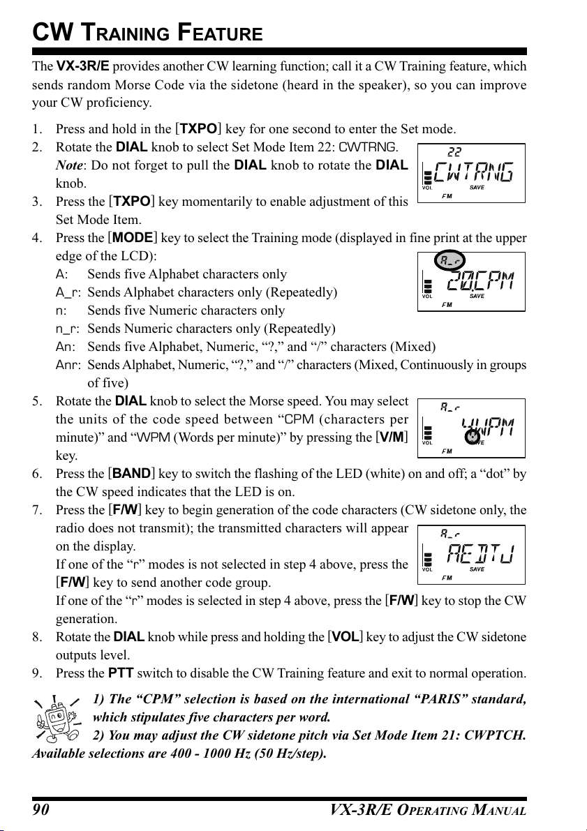
CW TRAINING FEATURE
The VX-3R/E provides another CW learning function; call it a CW Training feature, which
sends random Morse Code via the sidetone (heard in the speaker), so you can improve
your CW proficiency.
1. Press and hold in the [TXPO] key for one second to enter the Set mode.
2. Rotate the DIAL knob to select Set Mode Item 22: CWTRNG.
Note: Do not forget to pull the DIAL knob to rotate the DIAL
knob.
3. Press the [TXPO] key momentarily to enable adjustment of this
Set Mode Item.
4. Press the [MODE] key to select the Training mode (displayed in fine print at the upper
edge of the LCD):
A: Sends five Alphabet characters only
A_r: Sends Alphabet characters only (Repeatedly)
n: Sends five Numeric characters only
n_r: Sends Numeric characters only (Repeatedly)
An: Sends five Alphabet, Numeric, “?,” and “/” characters (Mixed)
Anr: Sends Alphabet, Numeric, “?,” and “/” characters (Mixed, Continuously in groups
of five)
5. Rotate the DIAL knob to select the Morse speed. You may select
the units of the code speed between “CPM (characters per
minute)” and “WPM (Words per minute)” by pressing the [V/M
key.
6. Press the [BAND] key to switch the flashing of the LED (white) on and off; a “dot” by
the CW speed indicates that the LED is on.
7. Press the [F/W] key to begin generation of the code characters (CW sidetone only, the
radio does not transmit); the transmitted characters will appear
on the display.
If one of the “r” modes is not selected in step 4 above, press the
[
F/W] key to send another code group.
If one of the “r” modes is selected in step 4 above, press the [F/W] key to stop the CW
generation.
8. Rotate the DIAL knob while press and holding the [VOL] key to adjust the CW sidetone
outputs level.
9. Press the PTT switch to disable the CW Training feature and exit to normal operation.
]
1) The “CPM” selection is based on the international “PARIS” standard,
which stipulates five characters per word.
2) You may adjust the CW sidetone pitch via Set Mode Item 21: CWPTCH.
Available selections are 400 - 1000 Hz (50 Hz/step).
VX-3R/E OPERATING MANUAL90
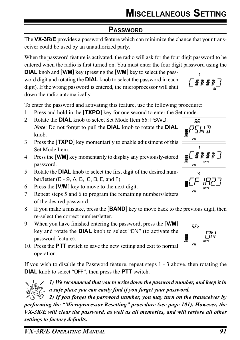
MISCELLANEOUS SETTING
PASSWORD
The VX-3R/E provides a password feature which can minimize the chance that your trans-
ceiver could be used by an unauthorized party.
When the password feature is activated, the radio will ask for the four digit password to be
entered when the radio is first turned on. You must enter the four digit password using the
DIAL knob and [V/M] key (pressing the [V/M] key to select the pass-
word digit and rotating the DIAL knob to select the password in each
digit). If the wrong password is entered, the microprocessor will shut
down the radio automatically.
To enter the password and activating this feature, use the following procedure:
1. Press and hold in the [TXPO] key for one second to enter the Set mode.
2. Rotate the DIAL knob to select Set Mode Item 66: PSWD.
Note: Do not forget to pull the DIAL knob to rotate the DIAL
knob.
3. Press the [TXPO] key momentarily to enable adjustment of this
Set Mode Item.
4. Press the [V/M] key momentarily to display any previously-stored
password.
5. Rotate the DIAL knob to select the first digit of the desired num-
ber/letter (0 - 9, A, B, C, D, E, and F).
6. Press the [V/M] key to move to the next digit.
7. Repeat steps 5 and 6 to program the remaining numbers/letters
of the desired password.
8. If you make a mistake, press the [BAND] key to move back to the previous digit, then
re-select the correct number/letter.
9. When you have finished entering the password, press the [V/M
key and rotate the DIAL knob to select “ON” (to activate the
password feature).
10. Press the PTT switch to save the new setting and exit to normal
operation.
]
If you wish to disable the Password feature, repeat steps 1 - 3 above, then rotating the
DIAL knob to select “OFF”, then press the PTT switch.
1) We recommend that you to write down the password number, and keep it in
a safe place you can easily find if you forget your password.
2) If you forget the password number, you may turn on the transceiver by
performing the “Microprocessor Resetting” procedure (see page 101). However, the
VX-3R/E will clear the password, as well as all memories, and will restore all other
settings to factory defaults.
VX-3R/E OPERATING MANUAL 91

MISCELLANEOUS SETTING
[ ]
PROGRAMMING THE
The Internet Key is the factory default (“primary” press key) function of the
K
EY
[ ]
key.
]
KEY
[ ]
key to another
However, you may change the “primary” (press key) function of the
function via the Set Mode.
1. Press and hold in the [TXPO] key for one second to enter the Set mode.
2. Rotate the DIAL knob to select Set Mode Item 42: INTKEY.
Note: Do not forget to pull the DIAL knob to rotate the DIAL
knob.
3. Press the [TXPO] key momentarily to enable adjustment of this
Set Mode Item.
4. Rotate the DIAL knob to select the desired function:
INTNET: Activates/Disables the internet feature.
INT MR: Recalls the Internet Access Number (SRG) or Access
String (FRG). Select the SRG number or FRG string via Set Mode Item 39:
INT MD.
SET MD: It is short cut path to recall one of the Set Mode Items. See below box for
programming.
5. When you have made your selection, press the PTT switch to save the new setting and
exit to normal operation.
When INT MR or SET MD is assigned to the [
may be activated/disabled via Set Mode Item 43: INTNET.
ASSIGN THE SET MODE ITEM TO THE
1. Change (“primary” press key) function of the
Mode Item 42: INTKEY, as descried above.
2. Press and hold in the [TXPO] key for one second to enter the Set mode again.
3. Rotate the DIAL knob to select the Set Mode Item which you wish to assign to
the [ ] key as a Menu short-cut.
Note: Do not forget to pull the DIAL knob to rotate the DIAL knob.
4. Press and hold in the
the [ ] key. “MY KEY” will appear on the display, to confirm that the com-
mand was executed.
5. Press the PTT switch to save the new setting and exit to normal operation.
[ ]
key for one second to assign the Set Mode Item to
] key, the INTNET function
[
[ ]
key to “SET MD”, via Set
Now, momentarily pressing of the
Set Mode Item. You must press the
[
]
key will immediately recall the selected
[ ]
key again to exit to normal operation.
VX-3R/E OPERATING MANUAL92
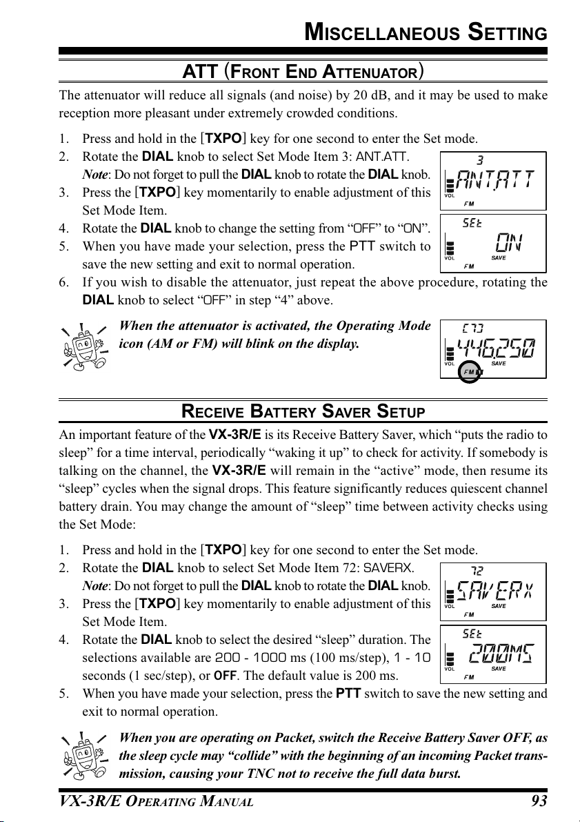
MISCELLANEOUS SETTING
ATT (FRONT END ATTENUATOR
The attenuator will reduce all signals (and noise) by 20 dB, and it may be used to make
reception more pleasant under extremely crowded conditions.
1. Press and hold in the [TXPO] key for one second to enter the Set mode.
2. Rotate the DIAL knob to select Set Mode Item 3: ANT.ATT.
Note: Do not forget to pull the DIAL knob to rotate the DIAL knob.
3. Press the [TXPO] key momentarily to enable adjustment of this
Set Mode Item.
4. Rotate the DIAL knob to change the setting from “OFF” to “ON”.
5. When you have made your selection, press the PTT switch to
save the new setting and exit to normal operation.
6. If you wish to disable the attenuator, just repeat the above procedure, rotating the
DIAL knob to select “OFF” in step “4” above.
When the attenuator is activated, the Operating Mode
icon (AM or FM) will blink on the display.
)
RECEIVE BATTERY SAVER SETUP
An important feature of the VX-3R/E is its Receive Battery Saver, which “puts the radio to
sleep” for a time interval, periodically “waking it up” to check for activity. If somebody is
talking on the channel, the VX-3R/E will remain in the “active” mode, then resume its
“sleep” cycles when the signal drops. This feature significantly reduces quiescent channel
battery drain. You may change the amount of “sleep” time between activity checks using
the Set Mode:
1. Press and hold in the [TXPO] key for one second to enter the Set mode.
2. Rotate the DIAL knob to select Set Mode Item 72: SAVERX.
Note: Do not forget to pull the DIAL knob to rotate the DIAL knob.
3. Press the [TXPO] key momentarily to enable adjustment of this
Set Mode Item.
4. Rotate the DIAL knob to select the desired “sleep” duration. The
selections available are 200 - 1000 ms (100 ms/step), 1 - 10
seconds (1 sec/step), or OFF. The default value is 200 ms.
5. When you have made your selection, press the PTT switch to save the new setting and
exit to normal operation.
When you are operating on Packet, switch the Receive Battery Saver OFF, as
the sleep cycle may “collide” with the beginning of an incoming Packet trans-
mission, causing your TNC not to receive the full data burst.
VX-3R/E OPERATING MANUAL 93
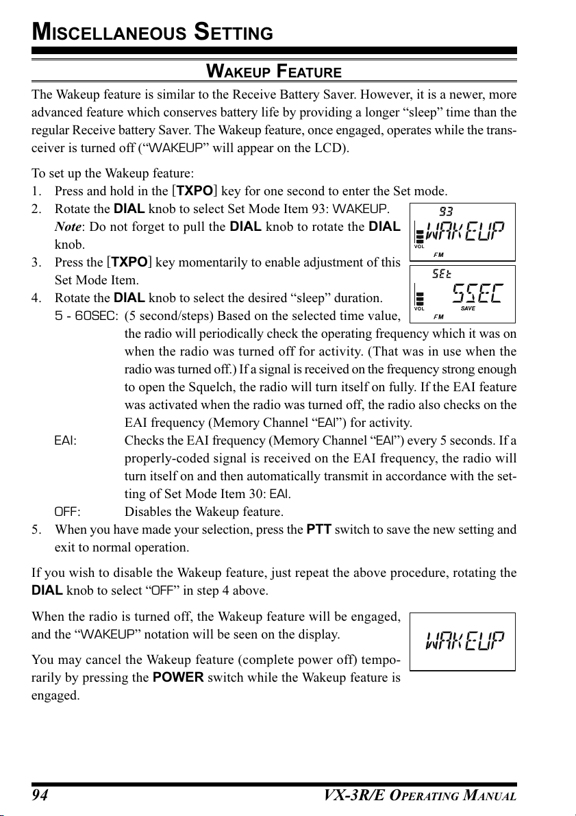
MISCELLANEOUS SETTING
WAKEUP FEATURE
The Wakeup feature is similar to the Receive Battery Saver. However, it is a newer, more
advanced feature which conserves battery life by providing a longer “sleep” time than the
regular Receive battery Saver. The Wakeup feature, once engaged, operates while the trans-
ceiver is turned off (“WAKEUP” will appear on the LCD).
To set up the Wakeup feature:
1. Press and hold in the [TXPO] key for one second to enter the Set mode.
2. Rotate the DIAL knob to select Set Mode Item 93: WAKEUP.
Note: Do not forget to pull the DIAL knob to rotate the DIAL
knob.
3. Press the [TXPO] key momentarily to enable adjustment of this
Set Mode Item.
4. Rotate the DIAL knob to select the desired “sleep” duration.
5 - 60SEC: (5 second/steps) Based on the selected time value,
the radio will periodically check the operating frequency which it was on
when the radio was turned off for activity. (That was in use when the
radio was turned off.) If a signal is received on the frequency strong enough
to open the Squelch, the radio will turn itself on fully. If the EAI feature
was activated when the radio was turned off, the radio also checks on the
EAI frequency (Memory Channel “EAI”) for activity.
EAI: Checks the EAI frequency (Memory Channel “EAI”) every 5 seconds. If a
properly-coded signal is received on the EAI frequency, the radio will
turn itself on and then automatically transmit in accordance with the set-
ting of Set Mode Item 30: EAI.
OFF: Disables the Wakeup feature.
5. When you have made your selection, press the PTT switch to save the new setting and
exit to normal operation.
If you wish to disable the Wakeup feature, just repeat the above procedure, rotating the
DIAL knob to select “OFF” in step 4 above.
When the radio is turned off, the Wakeup feature will be engaged,
and the “WAKEUP” notation will be seen on the display.
You may cancel the Wakeup feature (complete power off) tempo-
rarily by pressing the POWER switch while the Wakeup feature is
engaged.
VX-3R/E OPERATING MANUAL94

MISCELLANEOUS SETTING
TX BATTERY SAVER
The VX-3R/E also includes a useful Transmit Battery Saver, which will automatically
lower the power output level when the last signal received was very strong. For example,
when you are in the immediate vicinity of a repeater station, there generally is no reason to
use the High Power output in order to achieve full-quieting access to the repeater. With the
Transmit Battery Saver, the automatic selection of Low Power operation conserves battery
drain significantly.
To activate the Transmit Battery Saver:
1. Press and hold in the [TXPO] key for one second to enter the Set mode.
2. Rotate the DIAL knob to select Set Mode Item 73: SAVETX.
Note: Do not forget to pull the DIAL knob to rotate the DIAL
knob.
3. Press the [TXPO] key momentarily to enable adjustment of this
Set Mode Item.
4. Rotate the DIAL knob to set this Set Mode Item to “ON” (thus
activating the Transmit Battery Saver).
5. When you have made your selection, press the PTT switch to save the new setting and
exit to normal operation.
DISABLING THE BUSY INDICATOR
Further battery conservation may be accomplished by disabling the BUSY indicator while
receiving a signal. Use the following procedure:
1. Press and hold in the [TXPO] key for one second to enter the Set mode.
2. Rotate the DIAL knob to select Set Mode Item 16: BSY.LED.
Note: Do not forget to pull the DIAL knob to rotate the DIAL
knob.
3. Press the [TXPO] key momentarily to enable adjustment of this
Set Mode Item.
4. Rotate the DIAL knob to set this Set Mode Item to “OFF” (thus
disabling the BUSY lamp).
5. When you have made your selection, press the PTT switch to save the new setting and
exit to normal operation.
VX-3R/E OPERATING MANUAL 95

MISCELLANEOUS SETTING
AUTOMATIC POWER-OFF (APO) FEATURE
The APO feature helps conserve battery life by automatically turning the radio off when
there has been no dial or key activity for a user-defined period. The available selections for
the time before power-off are 0.5 - 12 hours (0.5 hour/step), as well as APO Off. The
default condition of the APO is OFF. This is the procedure to activate it:
1. Press and hold in the [TXPO] key for one second to enter the Set mode.
2. Rotate the DIAL knob to select Set Mode Item 4: APO.
Note: Do not forget to pull the DIAL knob to rotate the DIAL
knob.
3. Press the [TXPO] key momentarily to enable adjustment of this
Set Mode Item.
4. Rotate the DIAL knob to select the desired time period after which
the radio will automatically shut down.
5. When you have made your selection, press the PTT switch to save the new setting and
exit to normal operation.
When the APO is activated, the “ ” icon will appear at the center
bottom on the LCD. If there is no action by you within the time inter-
val programmed, a ringer sounds 3 minutes before the APO shut-
down time. Three minutes thereafter, the microprocessor will shut
down the radio automatically.
Just press and hold in the POWER switch for one second to turn the transceiver back on
after an APO shutdown, as usual.
VX-3R/E OPERATING MANUAL96
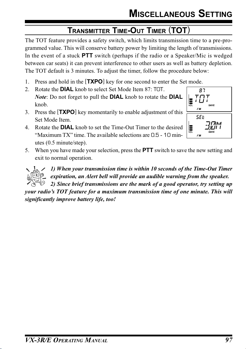
MISCELLANEOUS SETTING
TRANSMITTER TIME-OUT TIMER (TOT
The TOT feature provides a safety switch, which limits transmission time to a pre-pro-
grammed value. This will conserve battery power by limiting the length of transmissions.
In the event of a stuck PTT switch (perhaps if the radio or a Speaker/Mic is wedged
between car seats) it can prevent interference to other users as well as battery depletion.
The TOT default is 3 minutes. To adjust the timer, follow the procedure below:
1. Press and hold in the [TXPO] key for one second to enter the Set mode.
2. Rotate the DIAL knob to select Set Mode Item 87: TOT.
Note: Do not forget to pull the DIAL knob to rotate the DIAL
knob.
3. Press the [TXPO] key momentarily to enable adjustment of this
Set Mode Item.
4. Rotate the DIAL knob to set the Time-Out Timer to the desired
“Maximum TX” time. The available selections are 0.5 - 10 min-
utes (0.5 minute/step).
5. When you have made your selection, press the PTT switch to save the new setting and
exit to normal operation.
1) When your transmission time is within 10 seconds of the Time-Out Timer
expiration, an Alert bell will provide an audible warning from the speaker.
2) Since brief transmissions are the mark of a good operator, try setting up
your radio’s TOT feature for a maximum transmission time of one minute. This will
significantly improve battery life, too!
)
VX-3R/E OPERATING MANUAL 97

MISCELLANEOUS SETTING
AUTOMATIC POWER-ON FEATURE
The VX-3R/E also includes the capability to turn itself on after a programmed time interval.
1. Press and hold in the [TXPO] key for one second to enter the Set mode.
2. Rotate the DIAL knob to select Set Mode Item 58: ON TMR.
Note: Do not forget to pull the DIAL knob to rotate the DIAL
knob.
3. Press the [TXPO] key momentarily to enable adjustment of this
Set Mode Item.
4. Rotate the DIAL knob to set the desired time after which the radio will automatically
turn on. Note: that is not the time of day when the radio will turn
on; it is the number of hours and minutes until the radio turns on.
The available selections are 10 minutes - 24 hours (10 minute/
step).
5. When you have made your selection, press the PTT switch to save the new setting and
exit to normal operation.
When the radio is turned off, this activates the Automatic Power-On
feature; a countdown timer in the display will show the time remain-
ing until automatic switch-on.
You may cancel the Automatic Power-On feature (turn off the radio), by pressing and holding
the POWER switch for one second while the Automatic Power-On feature is engaged.
The Automatic Power-On feature will be ignored if the Wakeup feature is activated.
BUSY CHANNEL LOCK-OUT (BCLO
The BCLO feature prevents the radio’s transmitter from being activated if a signal strong
enough to break through the “noise” squelch is present. On a frequency where stations using
different CTCSS or DCS codes may be active, BCLO prevents you from disrupting their
communications accidentally (because your radio may be muted by its own Tone Decoder).
The default setting for the BCLO is OFF. This is the procedure to activate the BCLO:
1. Press and hold in the [TXPO] key for one second to enter the Set mode.
2. Rotate the DIAL knob to select Set Mode Item 8: BCLO.
Note: Do not forget to pull the DIAL knob to rotate the DIAL knob.
3. Press the [TXPO] key momentarily to enable adjustment of this
Set Mode Item.
4. Rotate the DIAL knob to set this Set Mode Item to “ON” (thus
activating the BCLO feature).
5. When you have made your selection, press the PTT switch to
save the new setting and exit to normal operation.
)
VX-3R/E OPERATING MANUAL98
 Loading...