

Yaesu G-450A INSTRUCTION MANUAL

G-450A
G-650A
Antenna Rotator & Controller
User Manual
YAESU MUSEN CO., LTD.
1-20-2 Shimomaruko, Ota-Ku, Tokyo 146-8649, Japan
YAESU U.S.A.
17210 Edwards Rd., Cerritos, CA 90703, U.S.A.
YAESU EUROPE B.V.
Snipweg 3, 1118DN Schiphol, The Netherlands
YAESU UK LTD.
Unit 12, Sun Valley Business Park, Winnall Trading Estate
Winchester, Hampshire, SO23 0LB, U.K.
YAESU GERMANY GmbH
Am Kronberger Hang 2, D-65824 Schwalbach, Germany
YAESU HK LTD.
11th Floor Tsim Sha Tsui Centre, 66 Mody Rd.,
Tsim Sha Tsui East, Kowloon, Hong Kong
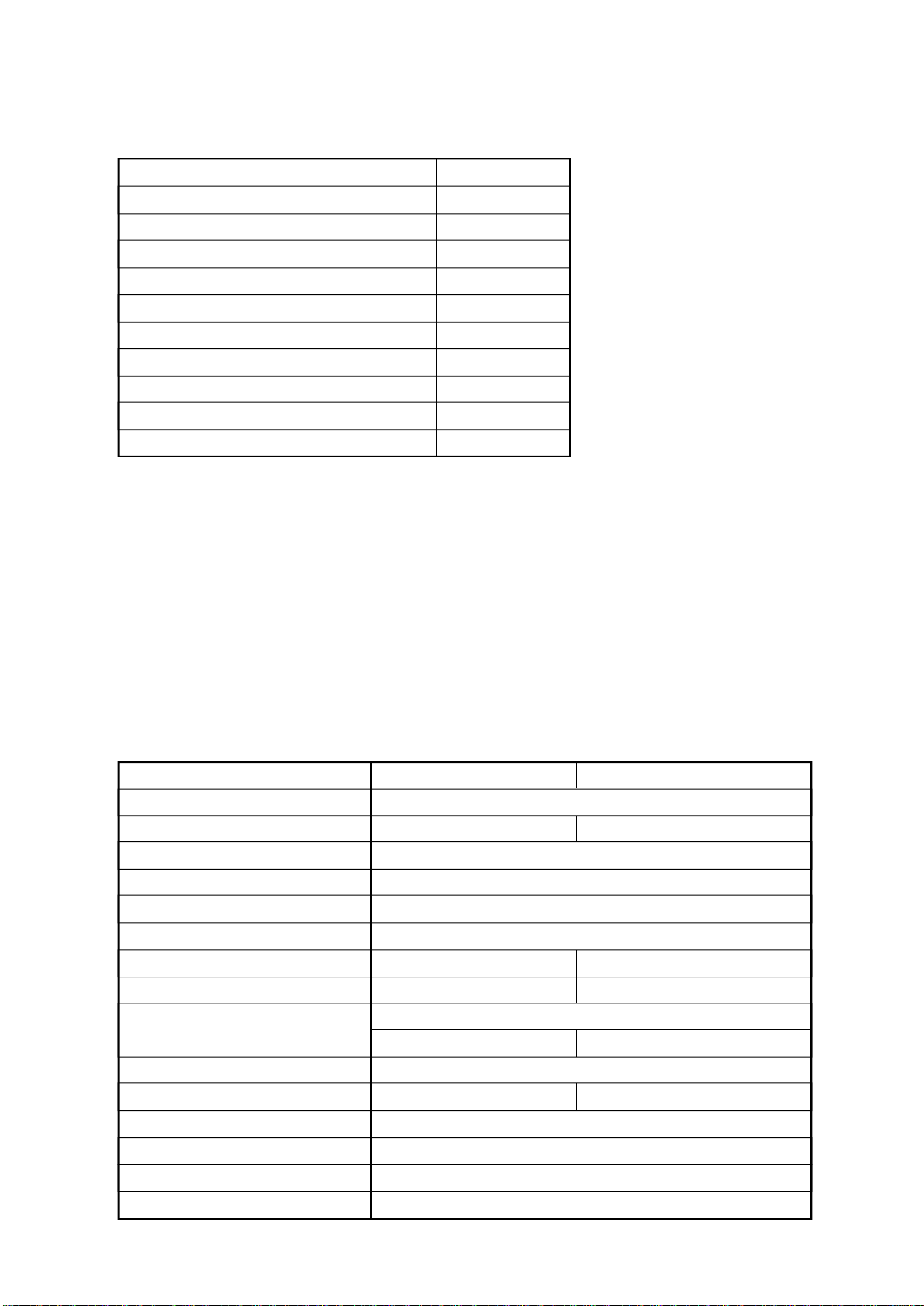
Packing List (Check Before Installing Rotator)
Rotor 1
Controller 1
U bolts 2
M8´16 Bolts 4
Hex. Nuts 4
Spring Washers 8
Flat Washers 4
7-pin Round Plug 1 set
6-pin Rectanglar Plug 1 set
Rubber Boot 1
User Manual 1
Available Options
GA-2500 Shock Absorber Plate
GS-680U Universal Bearing
GS-050 Thrust Bearing (50 mm mast)
GS-065 Thrust Bearing (65 mm mast)
GC-038B Mast Clamp
C-25MWP Control Cable (25 m)
C-40MWP Control Cable (40 m)
GL-33 Mast Adjustment Plate
Specifications
G-450A G-650A
Rotation Torque 600 kgf-cm (43 ft-lbs.)
Braking Torque 3000 kgf-cm (217 ft-lbs.) 5000 kgf-cm (362 ft-lbs.)
Maximum Vertical load Continuous load 100 kg or less (Instantaneous load 300 kg)
Mast Outside Diameter f32 to f63 (center protrudes by f48 to f52)
Rotation Range 450°
360° Rotation Time 63 seconds at 50 Hz, 51 seconds at 60 Hz
Braking Type Mechanical stopper Mechanical and electrical stoppers
Antenna K Coefficient 100 180
Wind Loading Area (Pole type) 0.5 m2 ´ 0.5 m
(Tower type) 1 m
Maximum Continuous Duty 3 minutes
Operating Temperature Range 0 ~ 40 °C: Controller -20 ~ 40 °C: Rotor
Rotor Dimensions and Weight f186 ´ 263, approx. 3.5 kg
Controller Dimensions and Weight
Power Supply Voltage AC 100 ~ 120 V, 50 ~ 60 Hz
Power Supply Current Consumption
190 (W) ´ 125 (H) ´ 150(D), approx. 2.7 kg
0.5 A
2
2 m
2
Installation/Operation Precautions
• Always use (Metric) M8x16 bolts when mounting the rotor to the tower or roof tripod mounting
plate.
• Take care not to scratch the surface of the rotator or its mounting hardware. If the protective
coating is scratched, the underlying metal may be subject to corrosion or rusting.
• During operation, do not suddenly reverse the rotation during operation, as this places a large load
on the internal components of the rotor. Let the antenna come to a complete stop before reversing
the direction of rotation.
• Do not engage the rotor for more than three minutes of continuous rotation. While this rotor can
operate for up to five minutes continuously, operation must thereafter be halted, and the motor
must be allowed to cool for at least 15 minutes afterwards.
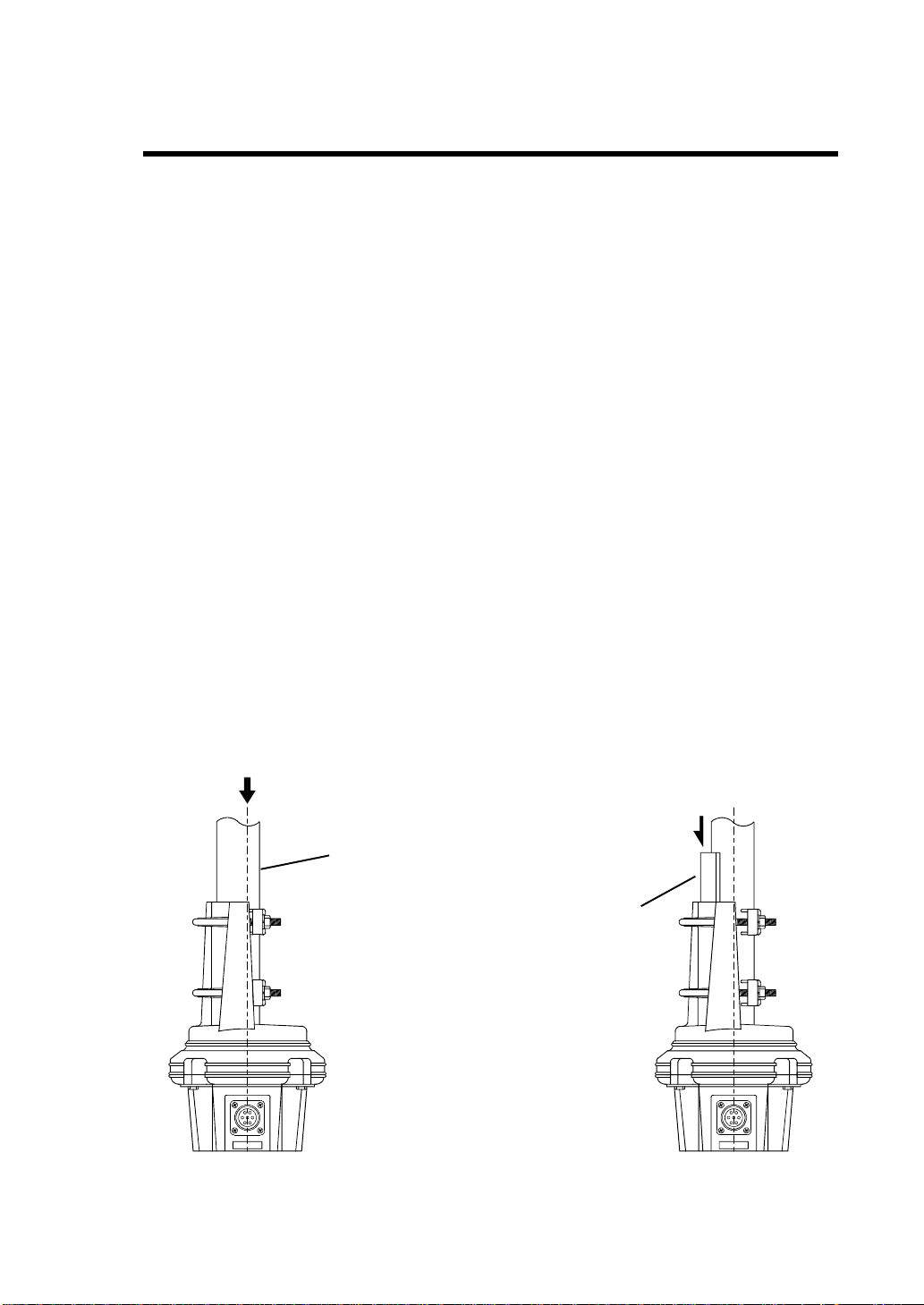
• This rotator is designed to provide centered rotation of a mast with an outside diameter* of
between 48 mm and 50 mm (1.89” to 1.97” O.D.). If it is necessary to use a mast of diameter less
than 48 ~ 50 mm, nearly centered rotation can be achieved using the optional “GL-33” mast
adjustment plate, per the illustrations below.
Mast Diameter f32 to f38: Use two plates.
Mast Diameter f39 to f47: Use one plate.
Mast Diameter f48 to f50: Do not use a plate.
• The use of a mast of outside diameter greater than 51 mm (2.01”) will result in off-center rotation.
The amount of offset increases with increasing mast diameter. A mast of 60 mm outside diameter
will result in rotation offset from the center by approximately 8 mm.
* Note that commonly-available steel “water pipe” is (A) usually specified in terms of inside
diameter, and (B) designed for holding in liquid under pressure; it is not particularly designed to
resist bending. Consult with your dealer or a professional tower/antenna installer for assistance
in procuring a mast of specifications adequate for your antenna system.
Center line
The rotation becomes off-centered for masts
with a diameter of less than f48.
Mast adjustment plate (Option)
Use two plates for mast diameters between f32 and f38.
Use one plate for mast diameters between f39 and f47.
Do not use a plate for mast diameters between f48 and f50.
Insert the mast adjustment plate(s) between the mast and the clamps on the rotor.
1
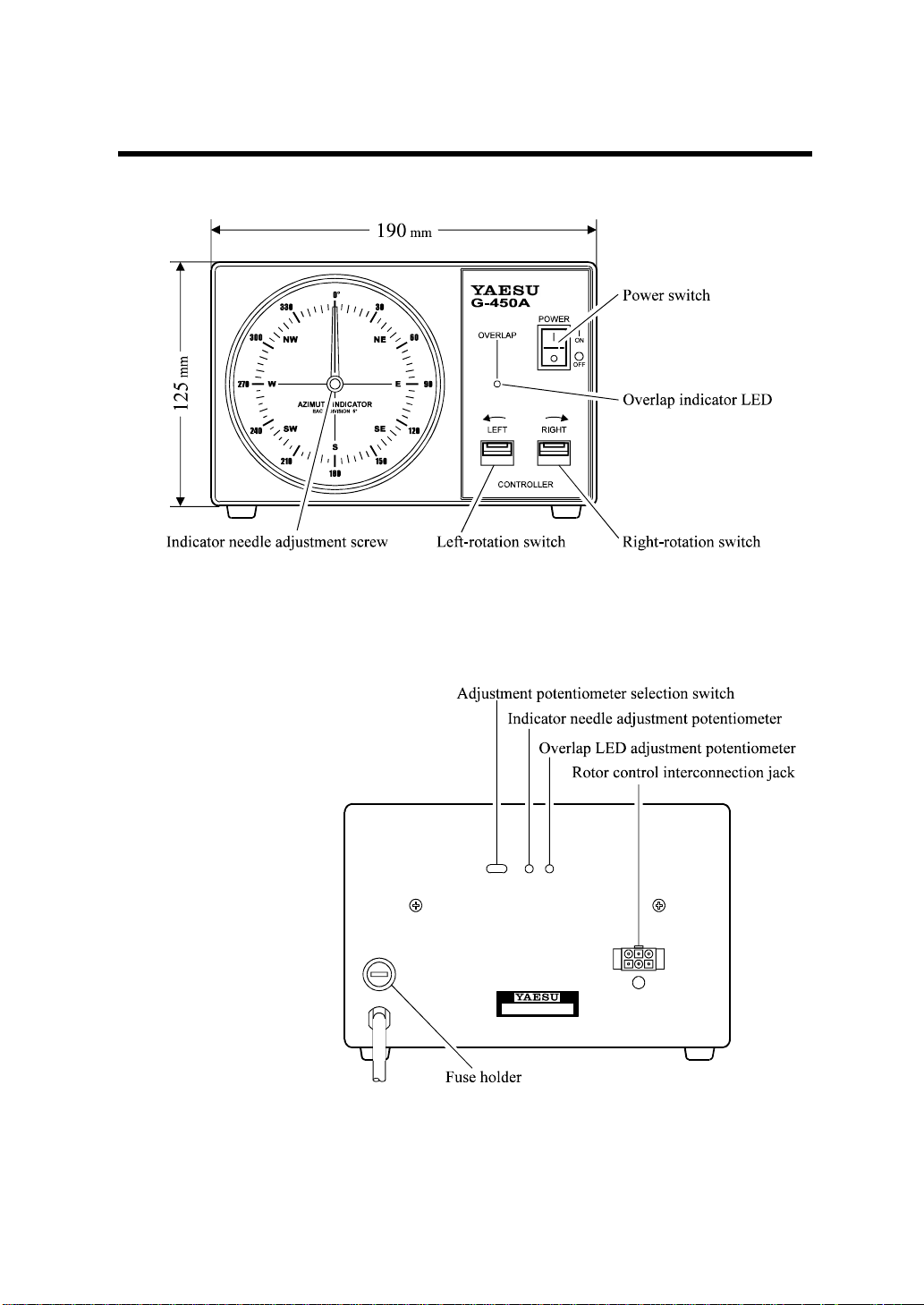
Controller Front/Rear Panel Controls and Switches
Controller Front Panel
Controller Rear Panel
When replacing fuses, be
sure to use a fuse of the same
type and current rating.
2
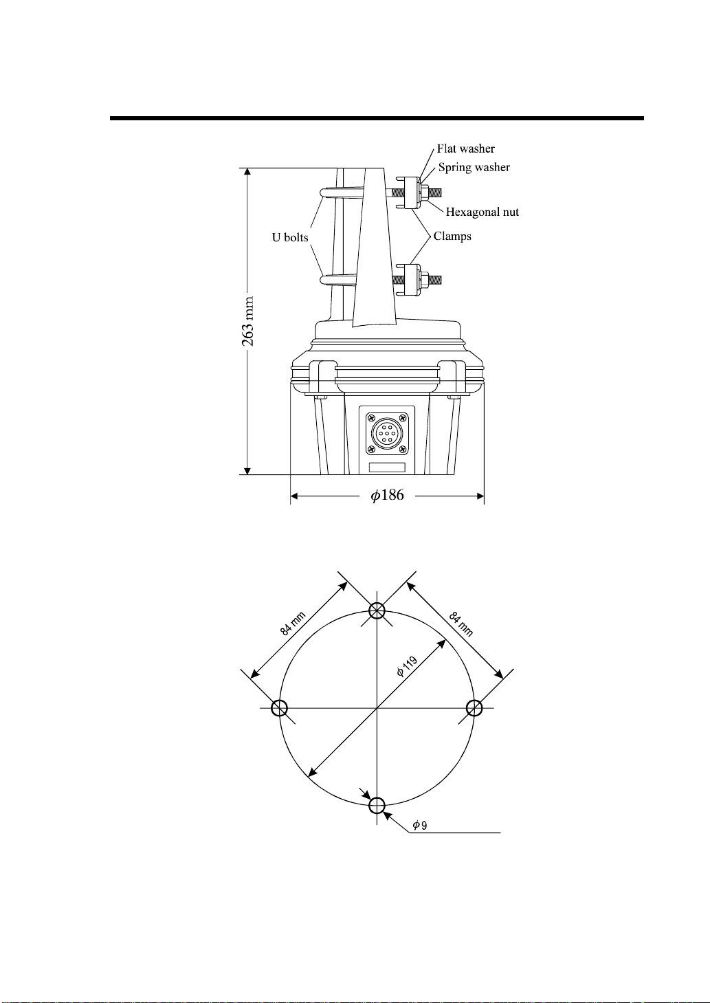
Rotator Unit Components and Dimensions
Rotator Unit
Rotator Attachment Plate Dimensions
The tower plate onto which the rotator unit is mounted must be drilled with four holes of 9 mm
diameter, equally spaced on a circle of 119 mm diameter. The center-to-center distance between
any two adjacent mounting holes is 84 mm.
3
 Loading...