


Yaesu FT-991 CAT, FT-991A Reference Book

FT-991
CAT OperATiOn
reFerenCe BOOk
YAESU MUSEN CO., LTD.
CAT
(CompuTer Aided TrAnsCeiver
)
operATion
Overview
The CAT (Computer Aided Transceiver) System in
the
FT-991
VFO, memory, and other settings such as dualchannel memories and diversity reception using an
external personal computer. This allows multiple
control operations to be fully automated with single
mouse clicks, or keystroke operations on the computer
keyboard.
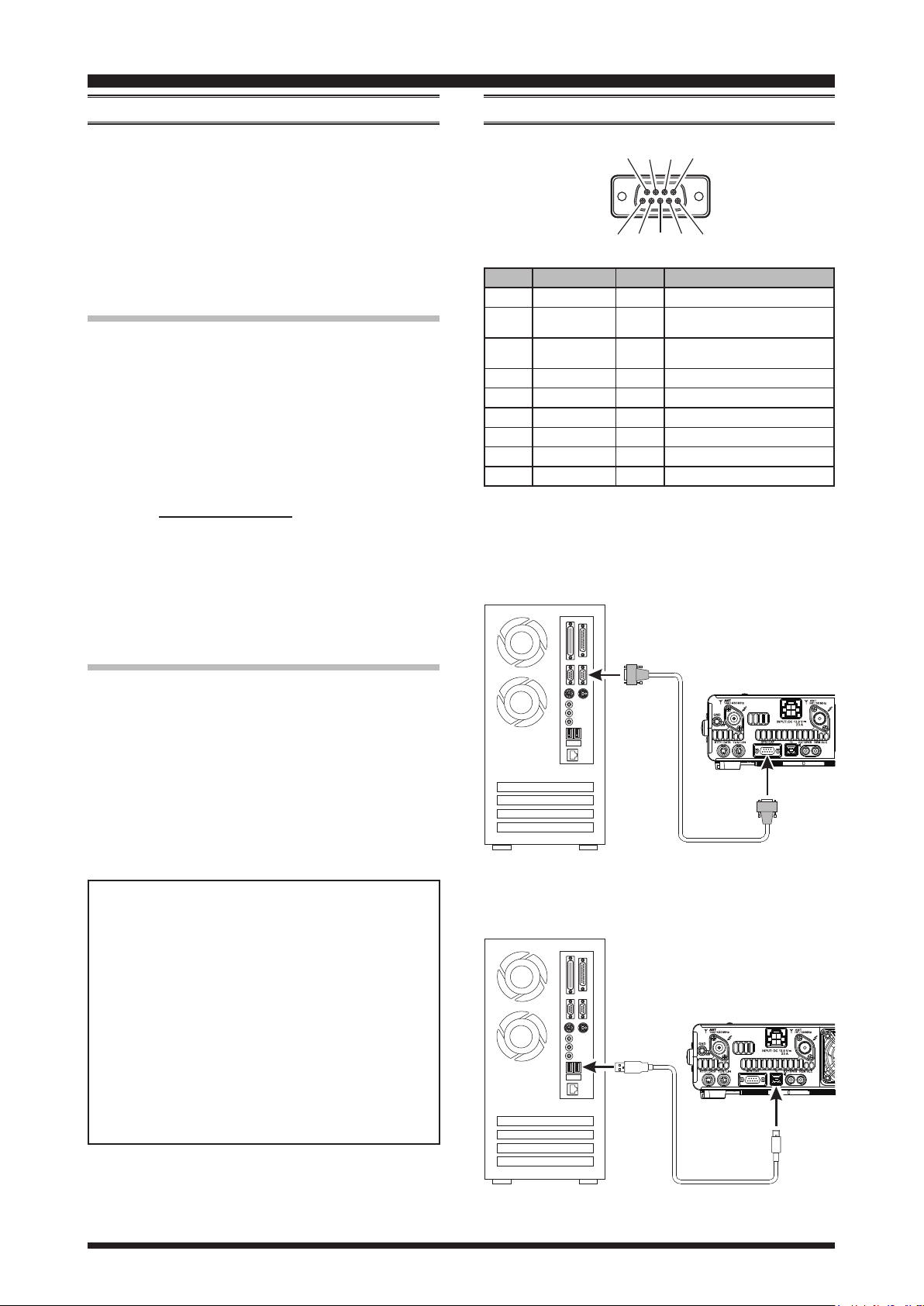
Using the RS-232C Cable
The
allowing direct connection from the rear-panel CAT jack
to the serial port of your computer without the need of
any external boxes.
When using the RS-232C cable, set Menu item “028
GPS/232C SELECT” to “RS232C”.
You will need a serial cable for connection to the RS232C (serial or COM port) connector on your computer.
Purchase a standard serial cable (not the so-called “null
modem” type), ensuring it has the correct gender and
number of pins (some serial COM port connectors use a
9-pin rather than 25-pin conguration). If your computer
uses a custom connector, you may have to construct the
cable. In this case, refer to the technical documentation
supplied with your computer for correct data connection.
transceiver provides control of frequency,
(Refer to gure 1)
FT-991
transceiver has a built-in level converter,
COnnectiOn
⑧⑨ ⑦ ⑥
①②③④⑤
Pin No. Pin Name I/O Function
Personal Computer
N/A --- ---
SERIAL OUT Output
SERIAL IN Input
N/A --- ---
GND --- Signal Ground
N/A --- ---
RTS --- ---
CTS --- ---
N/A --- ---
Outputs the Serial Data from
the transceiver to the computer.
Inputs the Serial Data from the
computer to the transceiver.
Using the USB Cable
: A USB driver is required for remote control from
Note
(Refer to gure 2)
a computer. Download the driver from the Yaesu
website (http://www.yaesu.com).
The
FT-991
transceiver has a built-in USB to Dual
UART Bridge, allowing direct connection from the
rear-panel USB jack to the USB jack of your computer
without the need of any external boxes.
You will need a USB cable to connect to the USB jack
on your computer.
YAESU MUSEN does not produce CAT System
operating software due to the wide variety of personal computers and operating systems in use today.
However, the information provided in this chapter
explains the serial data structure and opcodes used
by the CAT system. This information, along with
the short programming examples, is intended to
help you start writing programs on your own. As
you become more familiar with CAT operation, you
can customize programs for your operating needs
and utilize the full operating potential of this system.
Personal Computer
COM
RS-232C “Straight” Cable
Figure 1
USB
FT-991
GPS/CAT
FT-991
USB
Figure 2
FT-991 CAT Operation Manual1
USB Cable

CAT
(CompuTer Aided TrAnsCeiver
Control Command
)
operATion
A computer control command is composed of an alphabetical command, various parameters, and the terminator
that signals the end of the control command.
Example: Set the VFO-A frequency to 14.250000 MHz.
FA 014250000 ;
Command Parameter Terminator
There are three commands for the
low:
command: Set a particular condition
Set
command: Reads an answer
Read
Answer
For example, note the following case of the FA command (Set the VFO-A frequency):
To set the VFO-A frequency to 14.250000 MHz, the
following command is sent from the computer to the
transceiver:
“
To read the VFO-A frequency, the following com-
mand is sent from the computer to the transceiver:
“
When the Read command above has been sent, the
following command is returned to the computer:
“FA014250000;
command: Transmits a condition
FA014250000;
” (Read command)
FA;
” (Set command)
” (Answer command)
Ft-991
as shown be-
(to the
(from the
(from the
Ft-991
Ft-991
Ft-991
Alphabetical Commands
A command consists of 2 alphabetical characters.
You may use either lower or upper case characters. The
commands available for this transceiver are listed in the
“PC Control Command Tables” on the following pages.
Parameters
Parameters are used to specify information necessary to
implement the desired command.
The parameters to be used for each command are predetermined. The number of digits assigned to each
parameter is also predetermined. Refer to the “Control
Command List” and the “Control Command Tables” to
congure the appropriate parameters.
When configuring parameters, be careful not to make
the following mistakes.
)
)
)
For example,
when the correct parameter is “IS0+1000” (IF SHIFT):
IS01000;
Not enough parameters specied (No direction (+)
given for the IF shift)
IS0+100;
Not enough digits (Only three frequency digits
given)
IS0_+_1000;
Unnecessary characters between parameters
IS0+10000;
Too many digits (Five frequency digits given)
Note: If a particular parameter is not applicable to the
Ft-991
character except the ASCII control codes (00 to 1Fh)
and the terminator (;).
, the parameter digits should be lled using any
Terminator
To signal the end of a command, it is necessary to use
a semicolon (;). The digit where this special character
must appear differs depending on the command used.
FT-991 CAT Operation Manual2

CAT
(CompuTer Aided TrAnsCeiver
)
operATion
Command Function Set Read Ans. AI
AB VFO-A TO VFO-B O X X X
AC
AG AF GAIN O O O O
AI AUTO INFORMATION O O O X
AM
BA VFO-B TO VFO-A O X X X
BC AUTO NOTCH O O O O
BD BAND DOWN O X X X
BI BREAK-IN O O O O
BP MANUAL NOTCH O O O O
BS BAND SELECT O X X X
BU BAND UP O X X X
BY BUSY X O O O
CH CHANNEL UP/DOWN O X X X
CN CTCSS NUMBER O O O O
CO CONTOUR O O O O
CS CW SPOT O O O O
CT CTCSS O O O O
DA DIMMER O O O X
DN DOWN O X X X
DT DATE AND TIME O O O X
ED ENCORDER DOWN O X X X
EK ENT KEY O X X X
EU ENCORDER UP O X X X
EX MENU O O O O
FA FREQUENCY VFO-A O O O O
FB FREQUENCY VFO-B O O O O
FS FAST STEP O O O O
FT FUNCTION TX O O O O
GT AGC FUNCTION O O O O
ID IDENTIFICATION X O O X
IF INFORMATION X O O O
IS IF-SHIFT O O O O
KM KEYER MEMORY O O O X
KP KEY PITCH O O O O
KR KEYER O O O O
KS KEY SPEED O O O O
KY CW KEYING O X X X
LK LOCK O O O O
LM LOAD MESSEGE O O O X
MA
MC MEMORY CHANNEL O O O X
MD MODE O O O O
MG MIC GAIN O O O O
ML MONITOR LEVEL O O O O
MR MEMORY READ X O O X
MS METER SW O O O O
MW MEMORY WRITE O X X X
MX MOX SET O O O O
NA NARROW O O O O
NB NOISE BLANKER O O O O
NL
NR NOISE REDUCTION O O O O
OI
OS
PA PRE-AMP (IPO) O O O O
PB PLAY BACK O O O X
PC POWER CONTROL O O O O
PL
ANTENNA TUNER
CONTROL
VFO-A TO MEMORY
CHANNEL
MEMORY CHANNEL TO
VFO-A
NOISE BLANKER
LEVEL
OPPOSITE BAND
NFORMATION
OFFSET (Repeater
Shift)
SPEECH PROCESSOR
LEVEL
O O O O
O X X X
O X X X
O O O O
X O O O
O O O O
O O O O
Command Function Set Read Ans. AI
PR SPEECH PROCESSOR O O O O
PS POWER SWITCH O O O X
QI QMB STORE O X X X
QR QMB RECALL O X X X
QS QUICK SPLIT O X X X
RA RF ATTENUATOR O O O O
RC CLAR CLEAR O X X X
RD CLAR DOWN O X X X
RG RF GAIN O O O O
RI RADIO INFORMATION X O O O
RL
RM READ METER X O O O
RS RADIO STATUS X O O X
RT CLAR O O O O
RU CLAR UP O X X X
SC SCAN O O O O
SD
SH WIDTH O O O O
SM S METER X O O X
SQ SQUELCH LEVEL O O O O
SV SWAP VFO O X X X
TS TXW O O O O
TX TX SET O O O O
UL UNLOCK X O O O
UP UP O X X X
VD VOX DELAY TIME O O O O
VG VOX GAIN O O O O
VM [V/M] KEY FUNCTION O X X X
VX VOX O O O O
XT TX CLAR O O O O
ZI ZERO IN O X X X
NOISE REDUCTION
LEVEL
SEMI BREAK-IN DELAY
TIME
O O O O
O O O O
FT-991 CAT Operation Manual3

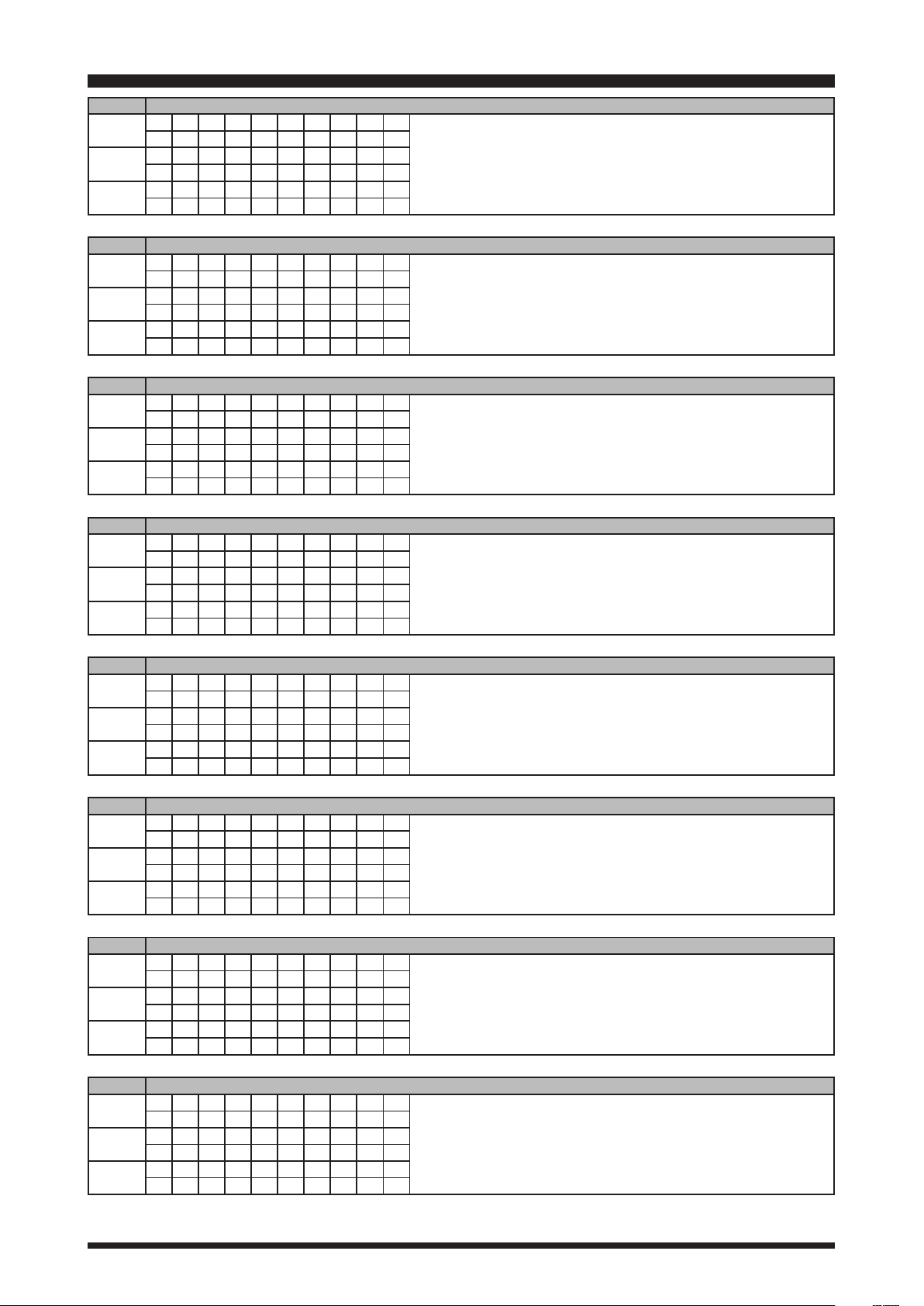
CAT
AB VFO-A TO VFO-B
Set
Read
Answer
AC ANTENNA TUNER CONTROL
Set
Read
Answer
AG AF GAIN
Set
Read
Answer
1 2 3 4 5 6 7 8 9 10
A B ;
1 2 3 4 5 6 7 8 9 10
1 2 3 4 5 6 7 8 9 10
1 2 3 4 5 6 7 8 9 10
A C P1 P2 P3 ;
1 2 3 4 5 6 7 8 9 10
A C ;
1 2 3 4 5 6 7 8 9 10
A C P1 P2 P3 ;
1 2 3 4 5 6 7 8 9 10
A G P1 P2 P2 P2 ;
1 2 3 4 5 6 7 8 9 10
A G P1 ;
1 2 3 4 5 6 7 8 9 10
A G P1 P2 P2 P2 ;
(CompuTer Aided TrAnsCeiver
P1 0: Fixed P3 0: Tuner “OFF”
P2 0: Fixed 1: Tuner “ON”
2: Tuning Start
P1 0: Fixed
P2 000 - 255
)
operATion
AI AUTO INFORMATION
Set
Read
Answer
AM VFO-A TO MEMORY CHANNEL
Set
Read
Answer
BA VFO-B TO VFO-A
Set
Read
Answer
BC AUTO NOTCH
Set
Read
Answer
1 2 3 4 5 6 7 8 9 10
A I P1 ;
1 2 3 4 5 6 7 8 9 10
A I ;
1 2 3 4 5 6 7 8 9 10
A I P1 ;
1 2 3 4 5 6 7 8 9 10
A M ;
1 2 3 4 5 6 7 8 9 10
1 2 3 4 5 6 7 8 9 10
1 2 3 4 5 6 7 8 9 10
B A ;
1 2 3 4 5 6 7 8 9 10
1 2 3 4 5 6 7 8 9 10
1 2 3 4 5 6 7 8 9 10
B C P1 P2 ;
1 2 3 4 5 6 7 8 9 10
B C P1 ;
1 2 3 4 5 6 7 8 9 10
B C P1 P2 ;
P1 0: Auto Information “OFF”
1: Auto Information “ON”
This parameter is set to “0” (OFF) automatically when the transceiver is turned “OFF”.
P1 0: Fixed
P2 0: Auto Notch “OFF”
1: Auto Notch “ON”
BD BAND DOWN
Set
Read
Answer
1 2 3 4 5 6 7 8 9 10
B D P1 ;
1 2 3 4 5 6 7 8 9 10
1 2 3 4 5 6 7 8 9 10
P1 0: Fixed
FT-991 CAT Operation Manual4
CAT
(CompuTer Aided TrAnsCeiver
BI BREAK-IN
Set
Read
Answer
1 2 3 4 5 6 7 8 9 10
B I P1 ;
1 2 3 4 5 6 7 8 9 10
B I ;
1 2 3 4 5 6 7 8 9 10
B I P1 ;
BP MANUAL NOTCH
Set
Read
Answer
1 2 3 4 5 6 7 8 9 10
B P P1 P2 P3 P3 P3 ;
1 2 3 4 5 6 7 8 9 10
B P P1 P2 ;
1 2 3 4 5 6 7 8 9 10
B P P1 P2 P3 P3 P3 ;
BS BAND SELECT
Set
Read
Answer
1 2 3 4 5 6 7 8 9 10
B S P1 P1 ;
1 2 3 4 5 6 7 8 9 10
1 2 3 4 5 6 7 8 9 10
)
operATion
P1 0: Break-in “OFF”
1: Break-in “ON”
P1 0: Fixed P3 P2=0
P2 0: Manual NOTCH “ON/OFF” 000: “OFF”
1: Manual NOTCH LEVEL 001: “ON”
P2=1
001 - 320
(NOTCH Frequency : x 10 Hz )
P1 00: 1.8 MHz 06: 18 MHz 12: MW
01: 3.5 MHz 07: 21 MHz 13: 02: - 08: 24.5 MHz 14: AIR
03: 7 MHz 09: 28 MHz 15: 144 MHz
04: 10 MHz 10: 50 MHz 16: 430 MHz
05: 14 MHz 11: GEN
BU BAND UP
Set
Read
Answer
1 2 3 4 5 6 7 8 9 10
B U P1 ;
1 2 3 4 5 6 7 8 9 10
1 2 3 4 5 6 7 8 9 10
BY BUSY
Set
Read
Answer
1 2 3 4 5 6 7 8 9 10
1 2 3 4 5 6 7 8 9 10
B Y ;
1 2 3 4 5 6 7 8 9 10
B Y P1 P2 ;
CH CHANNEL UP/DOWN
Set
Read
Answer
1 2 3 4 5 6 7 8 9 10
C H P1 ;
1 2 3 4 5 6 7 8 9 10
1 2 3 4 5 6 7 8 9 10
CN CTCSS TONE FREQUENCY
Set
Read
Answer
1 2 3 4 5 6 7 8 9 10
C N P1 P2 P2 ;
1 2 3 4 5 6 7 8 9 10
C N P1 ;
1 2 3 4 5 6 7 8 9 10
C N P1 P2 P2 ;
P1 0: Fixed
P1 0: RX BUSY “OFF”
1: RX BUSY “ON”
P2 0: Fixed
P1 0: Memory Channel “UP”
1: Memory Channel “DOWN”
P1 0: Fixed
P2 0 - 49: Tone Frequency Number (See Table 1)
CO CONTOUR
Set
Read
Answer
1 2 3 4 5 6 7 8 9 10
C O P1 P2 P3 P3 P3 P3 ;
1 2 3 4 5 6 7 8 9 10
C O P1 P2 ;
1 2 3 4 5 6 7 8 9 10
C O P1 P2 P3 P3 P3 P3 ;
P1 0: Fixed P3 P2=0 0000: CONTOUR “OFF”
P2 0: CONTOUR “ON/OFF” 0001: CONTOUR “ON”
1: CONTOUR FREQ P2=1 0010 - 3200
2: APF “ON/OFF” (CONTOUR Frequency:10 - 3200Hz)
3: APF FREQ P2=2 0000: APF “OFF”
0001: APF “ON”
P2=3 0000 - 0050 (
APF Frequency
: -250 - 250 Hz )
FT-991 CAT Operation Manual5
 Loading...