


Yaesu FT-710 Reference Manual

CAT Operation Reference Manual
YAESU MUSEN CO., LTD.
CAT
(Computer Aided Transceiver)
Operation
Overview
The CAT (Computer Aided Transceiver) System in the FT-710 transceiver provides control of frequency, VFO,
memory, and other settings such as dual-channel memories and diversity reception using an external personal
computer. This allows multiple control operations to be fully automated with single mouse clicks, or keystroke
operations on the computer keyboard.
YAESU MUSEN does not produce CAT System operating software due to the wide variety of personal computers
and operating systems in use today. However, the information provided in this chapter explains the serial data
structure and opcodes used by the CAT system. This information, along with the short programming examples,
is intended to help you start writing programs on your own. As you become more familiar with CAT operation,
you can customize programs for your operating needs and utilize the full operating potential of this system.
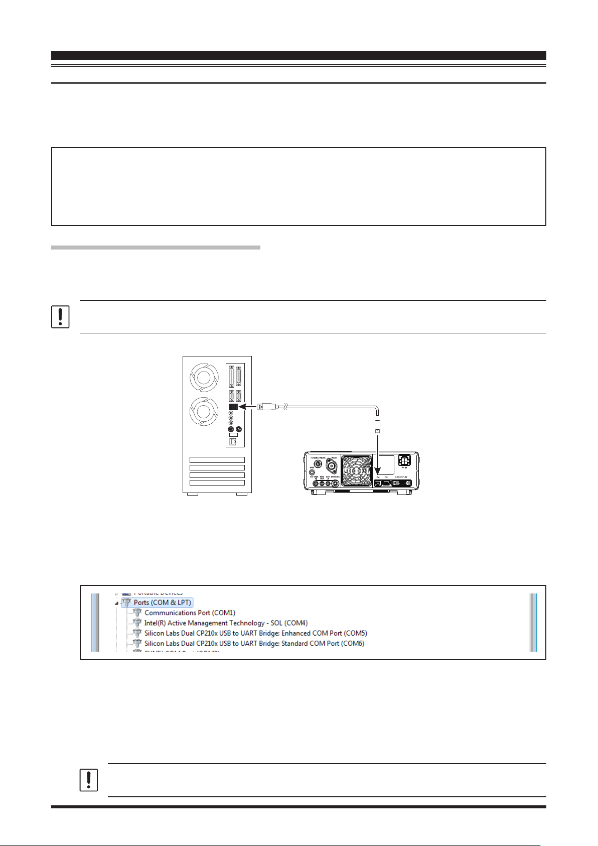
Using the USB Cable (CAT-1 / CAT-2)
The FT-710 transceiver has a built-in USB to Dual UART Bridge, allowing direct connection from the rear-panel
USB jack to the USB jack of a computer without the need for an interface device, simply use a USB cable to
connect to the USB jack on the computer.
To connect to a PC using a USB cable, a Virtual COM port driver must be installed on the PC.
Visit the Yaesu website http://www.yaesu.com/ to download the Virtual COM port driver and Installation Manual.
PC
USB Cable
USB
FT-710
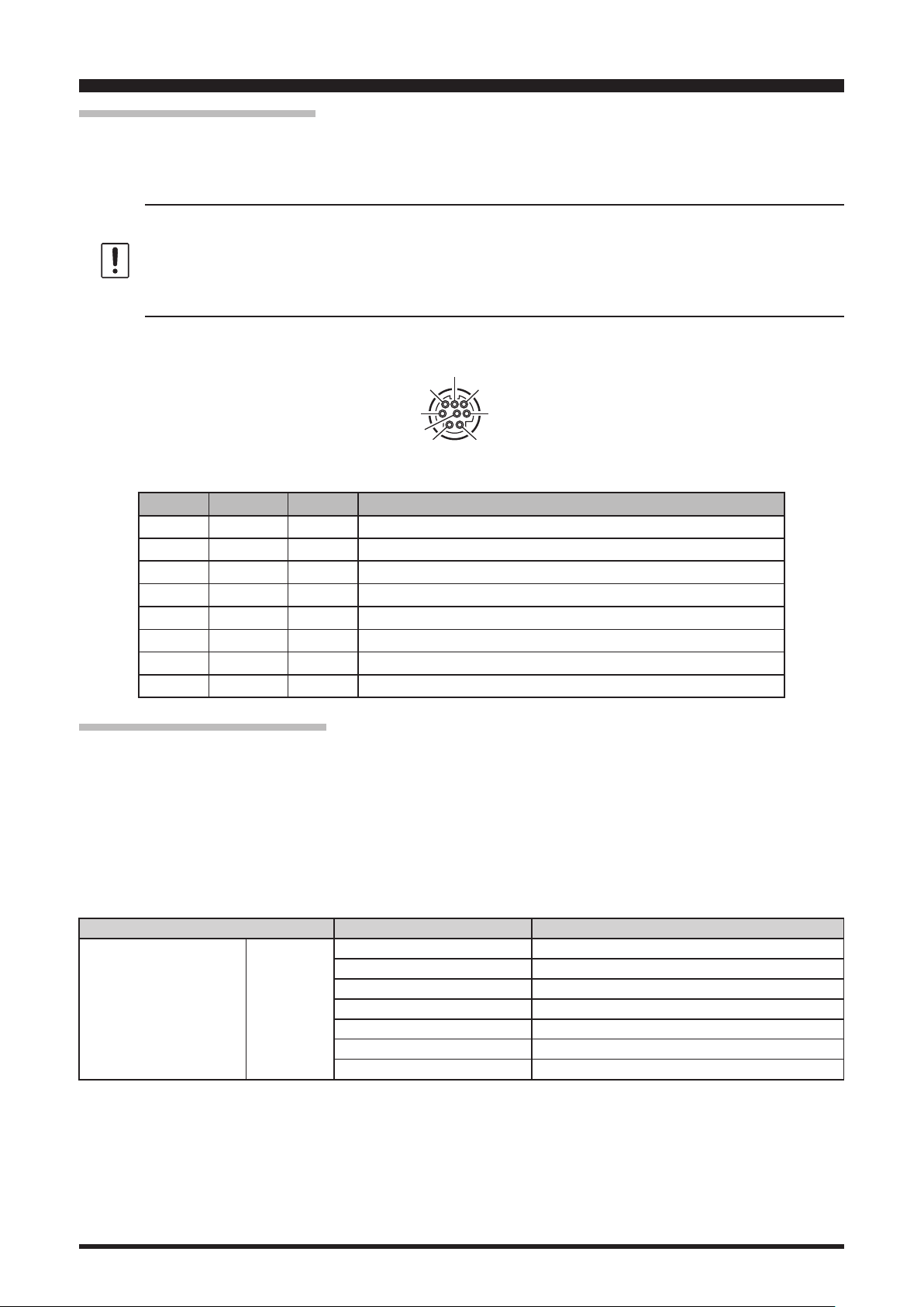
How to Conrm the Installation, and the COM Port Number
After the FT-710 and computer are connected, conrm that the virtual COM driver has been installed successfully:
1. Press and hold the ON/OFF switch to turn the transceiver ON.
2. Connect the transceiver and PC with a commercially available USB cable (A-B).
3. Open the “Device Manager” screen in Windows.
4. On the Device Manager screen, double-click “Port (COM & LPT)”.
USB
“Silicon Labs Dual CP210x USB to UART Bridge : Enhanced COM Port (COM**)”
“Silicon Labs Dual CP210x USB to UART Bridge : Standard COM Port (COM**)”
*(The number in the “(COM**)” portion may vary from computer to computer.)
The above example indicates that COM5 can be used for CAT communications (CAT-1), while COM6 can
be used for TX control (PTT, CW Keying, Digital Mode Operation) or CAT communications (CAT-2).
When performing software port conguration, select the COM port numbers that were conrmed using the
procedure above.
If a “!” or “X” is displayed for the port on the Device Manager, uninstall and reinstall the virtual
COM driver.
1

CAT
The FT-710 contains two virtual COM ports, an Enhanced COM Port and a Standard COM Port.
These ports oer the following functions:
• Enhanced COM Port (CAT-1): CAT Communications (Frequency and Communication Mode Settings)
• Standard COM Port (CAT-2): TX Controls (PTT control, CW Keying, Digital Mode Operation) or CAT
When performing software port conguration, select the COM port numbers that were conrmed using the
procedure above, use the two conrmed COM port numbers for each software function. The frequency and
communication mode and PTT control can be set from the software, and CW keying, digital communication,
etc. can be performed simultaneously.
*NOTE: (When using a standard COM port (CAT-2) for CAT communication (setting frequency, communication
mode, etc.) and using hardware ow control by RTS or DTR, be sure to set the following menu items to “OFF”
(factory default) or set to “DAKY” to disable PTT control by RTS or DTR.)
(Computer Aided Transceiver)
Communications (Frequency and Communication Mode Settings)*
Menu Item Menu Function Available Settings (Default: Bold)
MODE SSB RPTT SELECT OFF / RTS / DTR / DAKY
MODE AM RPTT SELECT OFF / RTS / DTR / DAKY
RADIO SETTING
CW SETTING
PRESET PRESET1 - 5 RPTT SELECT OFF / RTS / DTR / DAKY
MODE FM RPTT SELECT OFF / RTS / DTR / DAKY
MODE PSK/DATA RPTT SELECT OFF / RTS / DTR / DAKY
MODE RTTY RPTT SELECT OFF / RTS / DTR / DAKY
MODE CW
RPTT SELECT OFF / RTS / DTR / DAKY
PC KEYING OFF / RTS / DTR / DAKY
Operation
•
If a transceiver with a dierent serial number is connected and turned on, dierent COM port numbers
will be assigned to it, making it possible to perform individual COM port congurations for separate
transceivers.
•
When using the USB cable for TX control, the transceiver may switch to the transmit mode when the
computer is started.
•
Always close the application on the computer before disconnecting the USB cable.
2
CAT
⑤
+13V OUT
TUNER/LINEAR Jack
(as viewed from rear panel)
(Computer Aided Transceiver)
Operation
Using the RS-232C (CAT-3)
The TUNER/LINEAR jack on the rear panel can be used for CAT communication (5V TTL level serial communication).
Set to “CAT-3” in the setting menu [OPERATION SETTING] → [GENERAL] → [TUN/LIN PORT SELECT]. (Factory
setting: EXT-TUNER)
•
Since the serial communication of this jack is 5V TTL level, it cannot be directly connected to the RS-232C
terminal of the PC.
•
The connection cable must be prepared by yourself using the optional band data cable CT-58
(mini DIN 8-pin to DIN 8-pin).
•
CAT communication cannot be used simultaneously with an external antenna tuner or linear amplier.
⑦
⑧ ⑥
RX D
④ TX D
② ①
Pin No. Pin Name I/O Function
+13V – 13 VDC output linked to radio ON
N/A – –
GND – Signal Ground
TXD Output Outputs the Serial Data from the transceiver to the PC (5V TTL)
RXD Input Inputs the Serial Data from the PC to the transceiver (5V TTL)
N/A – –
N/A – –
N/A – –
③ GND
Communication Parameters
• Asynchronous communication
• Baud rate: 38400bps* (CAT-1, CAT-3 terminals) or 4800bps* (CAT-2 terminal)
• Start bit: 1
• Data bits: 8
• Stop bits: 1 or 2* (CAT-2: 1 (Fixed))
• Paritybits: None
*(Factory default)
CAT communication settings can be changed using the following menu items.
Menu Item Menu Function Available Settings (Default: Bold)
OPERATION SETTING GENERAL
CAT-1 RATE 4800 / 9600 / 19200 / 38400 / 115200 (bps)
CAT-1 TIME OUT TIMER 10 / 100 / 1000 / 3000 (msec)
CAT-1 CAT-3 STOP BIT 1bit / 2bit
CAT-2 RATE 4800 / 9600 / 19200 / 38400 / 115200 (bps)
CAT-2 TIME OUT TIMER 10 / 100 / 1000 / 3000 (msec)
CAT-3 RATE 4800 / 9600 / 19200 / 38400 / 115200 (bps)
CAT-3 TIME OUT TIMER 10 / 100 / 1000 / 3000 (msec)
3

CAT
(Computer Aided Transceiver)
Operation
Control Command
A computer control command is composed of an alphabetical command, various parameters, and the terminator
that signals the end of the control command.
Example: Set the VFO-A frequency to 14.250000 MHz.
FA 014250000 ;
Command Parameter Terminator
There are three commands for the FT-710 as shown below:
Set command: Set a particular condition (to the FT-710)
Read command: Reads an answer (from the FT-710)
Answer command: Transmits a condition (from the FT-710)
For example, note the following case of the FA command (Set the VFO-A frequency):
To set the VFO-A frequency to 14.250000 MHz, the following command is sent from the computer to the trans-
ceiver:
“FA014250000;” (Set command)
To read the VFO-A frequency, the following command is sent from the computer to the transceiver:
“FA;” (Read command)
When the Read command above has been sent, the following command is returned to the computer:
“FA014250000;” (Answer command)
Alphabetical Commands
A command consists of 2 alphabetical characters.
You may use either lower or upper case characters. The commands available for this transceiver are listed in the
“PC Control Command Tables” on the following pages.
Parameters
Parameters are used to specify information necessary to implement the desired command.
The parameters to be used for each command are predetermined. The number of digits assigned to each param-
eter is also predetermined. Refer to the “Control Command List” and the “Control Command Tables” to congure
the appropriate parameters.
When conguring parameters, be careful not to make the following mistakes.
For example,
when the correct parameter is “IS00+1000” (IF SHIFT):
IS001000;
Not enough parameters specied (No direction (+) given for the IF shift)
IS00+100;
Not enough digits (Only three frequency digits given)
IS00_+_1000;
Unnecessary characters between parameters
IS00+10000;
Too many digits (Five frequency digits given)
Note: If a particular parameter is not applicable to the FT-710, the parameter digits should be lled using any
character except the ASCII control codes (00 to 1Fh) and the terminator (;).
Terminator
To signal the end of a command, it is necessary to use a semicolon (;). The digit where this special character must
appear diers depending on the command used.
4

CAT
(Computer Aided Transceiver)
CAT Control Command List
Operation
Command
AB
AC
AG
AI
AM
AO
AS
AV
BA
BC
BD
BI
BM
BP
BS
BU
CF
CH
CN
CO
CS
CT
DA
DN
DT
EX
FA
FB
FN
FT
GP
GT
ID
IF
IS
KM
KP
KR
KS
KY
LK
LM
MA
MB
MC
MD
MG
Function Set Read Ans. AI
VFO-A TO VFO-B
ANTENNA TUNER
CONTROL
AF GAIN
AUTO INFORMATION
VFO-A TO MEMORY
CHANNEL
AMC OUTPUT LEVEL
AESS
ANTI VOX LEVEL
VFO-B TO VFO-A
AUTO NOTCH (DNF)
BAND DOWN
BREAK-IN
VFO-B TO MEMORY
CHANNEL
MANUAL NOTCH
BAND SELECT
BAND UP
CLAR (Clarier)
CHANNEL UP/DOWN
CTCSS NUMBER
CONTOUR/APF
CW SPOT
CTCSS
LCD CONTRAST/
DIMMER
DOWN
DATE AND TIME
MENU
FREQUENCY VFO-A
FREQUENCY VFO-B
FINE TUNING
FUNCTION TX
GP OUT A/B/C/D
AGC FUNCTION
IDENTIFICATION
INFORMATION (VFO-A)
IF SHIFT
KEYER MEMORY
KEY PITCH
KEYER
KEY SPEED
CW KEYING
LOCK
LOAD MESSAGE
MEMORY CHANNEL TO
VFO-A
MEMORY CHANNEL TO
VFO-B
MEMORY CHANNEL
MODE
MIC GAIN
O X X X
O O O O
O O O O
O O O X
O X X X
O O O O
O O O X
O O O O
O X X X
O O O O
O X X X
O O O O
O X X X
O O O O
O X X X
O X X X
O O O O
O X X X
O O O O
O O O O
O O O O
O O O O
O O O X
O X X X
O O O X
O O O O
O O O O
O O O O
O O O O
O O O O
O O O X
O O O O
X O O X
X O O O
O O O O
O O O X
O O O O
O O O O
O O O O
O X X X
O O O O
O O O X
O X X X
O X X X
O O O X
O O O O
O O O O
Command
ML
MR
MS
MT
MW
MX
NA
NB
NL
NR
OI
OS
PA
PB
PC
PL
PR
PS
QI
QR
RA
RG
RI
RL
RM
SC
SD
SF
SH
SM
SQ
SS
ST
SV
TS
TX
UP
VD
VE
VG
VM
VS
VX
ZI
Function Set Read Ans. AI
MONITOR LEVEL
MEMORY READ
METER SW
MEMORY CHANNEL
WRITE/TAG
MEMORY WRITE
MOX SET
NARROW
NOISE BLANKER
NOISE BLANKER LEVEL
NOISE REDUCTION (DNR)
OPPOSITE BAND (VFO-B)
INFORMATION
OFFSET (Repeater Shift)
PRE-AMP (IPO)
PLAY BACK
POWER CONTROL
SPEECH PROCESSOR
LEVEL
SPEECH PROCESSOR
POWER SWITCH
QMB STORE
QMB RECALL
RF ATTENUATOR
RF GAIN
RADIO INFORMATION
NOISE REDUCTION
(DNR) LEVEL
READ METER
SCAN
SEMI BREAK-IN DELAY
TIME
SUB DIAL
WIDTH
S METER
SQUELCH LEVEL
SPECTRUM SCOPE
SPLIT
SWAP VFO
TXW
TX SET
UP
VOX DELAY TIME
FIRMWARE VERSION
VOX GAIN
[V/M] KEY FUNCTION
VFO SELECT
VOX
ZERO IN
O O O O
X O O X
O O O O
O O O X
O X X X
O O O O
O O O O
O O O O
O O O O
O O O O
X O O O
O O O O
O O O O
O O O X
O O O O
O O O O
O O O O
O O O X
O X X X
O X X X
O O O O
O O O O
X O O O
O O O O
X O O O
O O O O
O O O O
O O O O
O O O O
X O O X
O O O O
O O O O
O O O O
O X X X
O O O O
O O O O
O X X X
O O O O
X O O X
O O O O
O X X X
O O O O
O O O O
O X X X
5
CAT
(Computer Aided Transceiver)
AB VFO-A TO VFO-B
Set
Read
Answer
1 2 3 4 5 6 7 8 9 10
A B ;
1 2 3 4 5 6 7 8 9 10
1 2 3 4 5 6 7 8 9 10
AC ANTENNA TUNER CONTROL
1 2 3 4 5 6 7 8 9 10
Set
A C P1 P2 P3 ;
1 2 3 4 5 6 7 8 9 10
Read
A C ;
1 2 3 4 5 6 7 8 9 10
Answer
A C P1 P2 P3 ;
AG AF GAIN
Set
Read
Answer
1 2 3 4 5 6 7 8 9 10
A G P1 P2 P2 P2 ;
1 2 3 4 5 6 7 8 9 10
A G P1 ;
1 2 3 4 5 6 7 8 9 10
A G P1 P2 P2 P2 ;
Operation
P1 0: (Fixed)
P2 0: Internal or External Antenna Tuner
1: 2: ATAS
P3 P2=0 (Antenna Tuner):
0: Tuner “OFF” (Tuning Stop)
1: Tuner “ON”
2: Tuning Start
P2=2 (ATAS):
0: Tuning Stop
1: Tuning frequency up (50 msec)
2: Tuning frequency down (50 msec)
3: Tuning Start
P1 0: (Fixed)
P2 000 - 255
AI AUTO INFORMATION
Set
Read
Answer
1 2 3 4 5 6 7 8 9 10
A I P1 ;
1 2 3 4 5 6 7 8 9 10
A I ;
1 2 3 4 5 6 7 8 9 10
A I P1 ;
AM VFO-A TO MEMORY CHANNEL
Set
Read
Answer
1 2 3 4 5 6 7 8 9 10
A M ;
1 2 3 4 5 6 7 8 9 10
1 2 3 4 5 6 7 8 9 10
AO AMC OUTPUT LEVEL
Set
Read
Answer
1 2 3 4 5 6 7 8 9 10
A O P1 P1 P1 ;
1 2 3 4 5 6 7 8 9 10
A O ;
1 2 3 4 5 6 7 8 9 10
A O P1 P1 P1 ;
AS AESS
Set
Read
Answer
1 2 3 4 5 6 7 8 9 10
A S P1 P2 P2 P2 ;
1 2 3 4 5 6 7 8 9 10
A S P1 ;
1 2 3 4 5 6 7 8 9 10
A S P1 P2 P2 P2 ;
P1 0: Auto Information “OFF”
1: Auto Information “ON”
NOTES:
• When the status of the radio changes, the Read value of the AI applicable command (see
“CAT Control Command List” (page 5)) is automatically sent to the PC.
• Set ON/OFF for each CAT-1, CAT-2, and CAT-3.
• This parameter is set to “0” (OFF) automatically when the transceiver is turned “OFF”.
P1 001-100: AMC OUTPUT LEVEL
P1 1: AESS LEVEL
2: AESS-CF (Cut o frquecny)
P2 P1=1 (AESS LEVEL):
P2: 000 - 100
P1=2 (AESS-CF (Cut o frquecny)):
001: 700Hz
002: 1000Hz
6
CAT
(Computer Aided Transceiver)
AV ANTI VOX LEVEL
Set
Read
Answer
1 2 3 4 5 6 7 8 9 10
A V P1 P1 P1 ;
1 2 3 4 5 6 7 8 9 10
A V ;
1 2 3 4 5 6 7 8 9 10
A V P1 P1 P1 ;
BA VFO-B TO VFO-A
Set
Read
Answer
1 2 3 4 5 6 7 8 9 10
B A ;
1 2 3 4 5 6 7 8 9 10
1 2 3 4 5 6 7 8 9 10
BC AUTO NOTCH
Set
Read
Answer
1 2 3 4 5 6 7 8 9 10
B C P1 P2 ;
1 2 3 4 5 6 7 8 9 10
B C P1 ;
1 2 3 4 5 6 7 8 9 10
B C P1 P2 ;
Operation
P1 001-100: ANTI VOX LEVEL
P1 0: (Fixed)
P2 0: Auto Notch “OFF”
1: Auto Notch “ON”
BD BAND DOWN
Set
Read
Answer
1 2 3 4 5 6 7 8 9 10
B D P1 ;
1 2 3 4 5 6 7 8 9 10
1 2 3 4 5 6 7 8 9 10
BI BREAK-IN
Set
Read
Answer
1 2 3 4 5 6 7 8 9 10
B I P1 ;
1 2 3 4 5 6 7 8 9 10
B I ;
1 2 3 4 5 6 7 8 9 10
B I P1 ;
BM VFO-B TO MEMORY CHANNEL
Set
Read
Answer
1 2 3 4 5 6 7 8 9 10
B M ;
1 2 3 4 5 6 7 8 9 10
1 2 3 4 5 6 7 8 9 10
BP MANUAL NOTCH
Set
Read
Answer
1 2 3 4 5 6 7 8 9 10
B P P1 P2 P3 P3 P3 ;
1 2 3 4 5 6 7 8 9 10
B P P1 P2 ;
1 2 3 4 5 6 7 8 9 10
B P P1 P2 P3 P3 P3 ;
P1 0: MAIN BAND
1: SUB BAND
P1 0: Break-in “OFF”
1: Break-in “ON”
P1 0: (Fixed)
P2 0: Manual NOTCH “ON/OFF”
1: Manual NOTCH Frequency
P3 P2=0
000: “OFF”
001: “ON”
P2=1
001 - 320 (NOTCH Frequency : x 10 Hz )
BS BAND SELECT
Set
Read
Answer
1 2 3 4 5 6 7 8 9 10
B S P1 P1 ;
1 2 3 4 5 6 7 8 9 10
1 2 3 4 5 6 7 8 9 10
P1 00: 1.8 MHz 06: 18 MHz
01: 3.5 MHz 07: 21 MHz
02: 5 MHz 08: 24.5 MHz
03: 7 MHz 09: 28 MHz
04: 10 MHz 10: 50 MHz
05: 14 MHz 11: 70 MHz/GEN
7