

Page 1
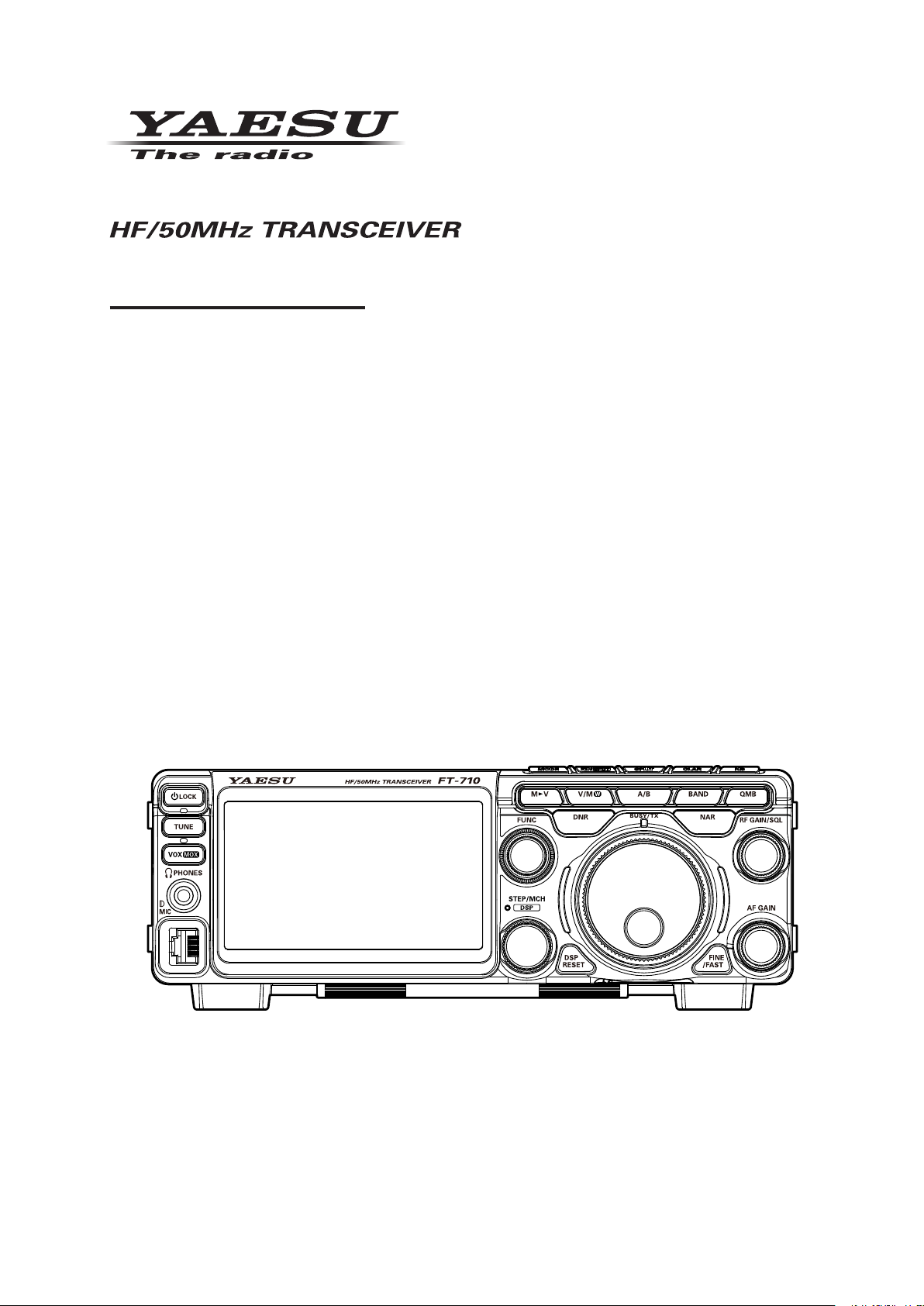
FT-710
Operation Manual
Page 2

Page 3

About this Manual
The FT-710 is a leading-edge transceiver with a number of new and exciting features, some of which may
be unfamiliar to you. In order to gain the most enjoyment and operating eciency from the FT-710, we
recommend that you read this manual in its entirety, and keep it handy for reference as you explore the
many capabilities of this new transceiver.
Before using the FT-710, be sure to read this manual.
How to read this operation manual
Two methods are used to select an item displayed on the FT-710 Function Screen: “Operate by touching the item directly on the display”; and “Turn the [FUNC] knob to select the item and then press
the [FUNC] knob”.
Subsequently, in this manual, the operations that can be performed either by touching the Function
Screen, or by turning and pressing the [FUNC] knob are abbreviated to “Select [DISPLAY SETTING] →
[DISPLAY] → [LED DIMMER]”; as described in the following:
Example: How to adjust the brightness of the LED
1. Press the [FUNC] knob to display the function screen.
2. Touch [DISPLAY SETTING] on the function screen, or rotate the [FUNC] knob to select [DISPLAY
SETTING] and then press the [FUNC] knob.
3. Touch [DISPLAY] on the display or rotate the [FUNC] knob to select [DISPLAY] and then press the
[FUNC] knob.
4. Touch the setting section of [LED DIMMER] on the display, or rotate the [FUNC] knob to select [LED
DIMMER] and then press the [FUNC] knob.
5. Rotate the [FUNC] knob, or touch “<” or “>” on either side of the value to adjust the brightness.
The following notations are also used in this manual:
This icon indicates cautions and alerts the user should be aware of.
This icon indicates helpful notes, tips and information.
1
Page 4
Table of Contents
General Description ........................................4
Safety Precautions .........................................6
Accessories & Options ...................................8
Installation and Interconnections ....................9
Antenna Considerations ..................................... 9
Antenna Connections ......................................... 9
Power Cable Connections .................................. 9
Microphone, Headphone, Key, Keyer and
FH-2 Connections ............................................ 10
Linear Amplier Interconnections ..................... 11
VL-1000 Linear Amplier Interconnections .... 11
Display connections ......................................... 12
Remote operation (LAN unit “SCU-LAN10”)
connection ........................................................ 12
AESS (Acoustic Enhanced
Speaker System) ..........................................13
SP-40 connections ........................................... 13
Rear Panel....................................................14
TUNER/LINEAR ....................................... 14
ANT ........................................................... 14
GND .......................................................... 14
EXT SPKR ................................................ 14
REM/ALC .................................................. 14
KEY........................................................... 14
RTTY/DATA .............................................. 14
USB .......................................................... 14
USB Jack .................................................. 14
EXT-DISPLAY ........................................... 14
DC IN ........................................................ 14
SSM-75E Microphone Switches ...................15
Display Indications........................................16
Meter Display ............................................ 17
Operation MODE Display ......................... 17
Operation status Display .......................... 17
HI-SWR Display ........................................ 17
Frequency Display (VFO-A) ..................... 18
Keyboard Frequency Entry ...................... 18
Tuning in 1 MHz or 1 kHz Steps ............... 18
Frequency Display (VFO-B) ..................... 18
When the clarier function is active .......... 18
Operation of the display [FUNC] knob ...... 19
Filter Function Display .............................. 20
Turn the spectrum display OFF ................ 20
Information displayed on the
scope screen ............................................ 20
Important Receiver Settings ..................... 21
ATT (Attenuator) ....................................... 21
IPO ........................................................... 21
DNF (Digital NOTCH Filter) ...................... 21
AGC (Automatic Gain Control) ................. 21
Information displayed on
the scope screen ...................................... 22
Scope Display Setting .............................. 22
CENTER/CURSOR/FIX ........................... 22
CENTER................................................... 22
CURSOR .................................................. 22
FIX ............................................................ 23
3DSS ........................................................ 23
MULTI ....................................................... 23
EXPAND ................................................... 24
SPAN ........................................................ 24
SPEED ..................................................... 24
Set with the FUNC knob ........................... 25
LEVEL ...................................................... 25
PEAK ........................................................ 25
MARKER .................................................. 26
COLOR..................................................... 26
Adjust contrast.......................................... 26
Adjusting the brightness (DIMMER) ......... 26
Other display settings ........................................ 27
Screen Saver ................................................. 27
Inputting the Call Sign ................................... 27
Front Panel Controls & Switches ..................30
ON/OFF (LOCK) Switch ........................... 30
SD memory card slot ................................ 30
TUNE ........................................................ 30
VOX/MOX ................................................. 30
Adjusts the VOX GAIN ............................. 30
Adjusts the VOX Delay Time .................... 30
Adjusts the VOX anti-trip sensitivity ......... 31
PHONES Jack .......................................... 31
MIC ........................................................... 31
MAIN dial .................................................. 31
WIRE STAND ........................................... 31
STEP•MCH /
DSP interference removal functions ......... 32
1. SHIFT ................................................... 33
2. WIDTH.................................................. 33
3. NOTCH................................................. 33
4. CONTOUR ........................................... 34
Adjusting the GAIN of the
CONTOUR Circuit ................................ 34
Sets the Bandwidth (“Q”) of the
CONTOUR Circuit ................................ 34
5. APF....................................................... 34
DSP RESET ............................................. 34
DNR (Digital Noise Reduction) ................. 35
Adjusting the DNR Level ........................... 35
A/B ............................................................ 35
BAND (
QMB (Quick Memory Bank) ...................... 35
QMB Channel Storage ............................. 35
QMB Channel Recall ................................ 35
Changing the number of QMB channels .. 35
VMI (VFO mode indicator) ........................ 36
BUSY/TX indicator .................................... 36
NAR (Narrow) ........................................... 36
FINE/FAST................................................ 36
RF GAIN/SQL ........................................... 37
Switching the operation of the
[RF GAIN/SQL] knob ................................ 37
Operating Band Selection
............................... 32
) ................ 35
2
Page 5

AF GAIN ................................................... 37
MODE (Operating Mode Selection) .......... 37
ZIN/SPOT ................................................. 38
SPLIT ........................................................ 38
CLAR (Clarier) ........................................ 38
RX Clarier ............................................... 38
Adjust transmit frequency to the
oset frequency ........................................ 38
TX Clarier ............................................... 39
To oset the frequency with the
TX Clarier Adjust receive frequency ....... 39
NB ............................................................. 39
Adjusting the Noise Blanker Level ........... 39
Adjusting the Noise Attenuation ...............39
Reduces longer duration pulse noise ....... 39
Voice Communications (SSB and AM) .........40
When transmitting in SSB or AM mode ............ 40
Set with the FUNC knob ................................... 40
Speech Processor ............................................ 41
RF Power output control ................................... 41
MONI (Monitor) ................................................. 41
Parametric Microphone Equalizer .................... 42
Setup the ...................................................... 42
Parametric Microphone Equalizer ................. 42
Activate the ................................................... 42
Parametric Microphone Equalizer ................. 42
Voice Memory ...................................................44
Record the received audio ............................... 45
Play the recorded content ............................. 45
Erase the recorded content ........................... 45
Adjustable Receiver Audio Filter ......................46
Change the sound quality of the
received audio .................................................. 47
Using the Automatic Antenna Tuner ................. 48
CW Mode Operation .....................................49
Adjusting the Sidetone Audio level ................ 49
CW Delay Time Setting .................................49
CW Spotting (Zero-Beating) ............................. 49
Setting of the Electronic Keyer ......................... 50
Adjusting the Keyer Speed ............................ 50
Setting the Keyer Weight (Dot/Dash) Ratio ... 50
Reversing the Keyer Polarity ......................... 50
Selecting the Keyer Operating Mode ............ 50
Contest Memory Keyer ..................................... 51
Message Memory .......................................... 51
Storing a Message into Memory .................... 51
Message Memory Programming ................... 51
(Using your Paddle) ....................................... 51
Checking the CW Memory Contents ............. 52
On-The-Air CW Message Playback .............. 52
TEXT Memory ............................................... 53
Text Memory Storage .................................... 53
Text Message Programming .......................... 53
Checking the CW Memory Contents ............. 54
On-The-Air CW Message Playback .............. 54
FM Mode Operation......................................55
Repeater Operation .......................................... 55
Tone Squelch Operation ................................... 55
DATA (FT8 / RTTY / PSK) Operation ............ 56
Connecting to a Personal Computer ................ 56
FT8 operation ................................................... 57
RTTY Operation ............................................... 58
PSK Operation ................................................. 58
Memory Operation ........................................60
M►V ......................................................... 60
Moving Memory Data to the
VFO register ............................................. 60
Transfer last used memory to VFO .......... 60
V/M ....................................................... 60
Memory Storage ....................................... 60
Recall a Memory Channel other than
the last used VFO frequency .................... 61
Memory Tune Operation........................... 61
Memory Groups........................................ 61
Choosing the Desired Memory Group ...... 61
Erasing Memory Channel Data ................ 62
Check Memory Channel Status................ 62
Labeling Memories ................................... 62
Displaying the Memory Tag ...................... 62
Scan Skip Setting ..................................... 63
60-Meter (5 MHz) Band
(U.S. and U.K. Version only) ....................63
VFO and Memory Scanning .........................64
VFO/Memory Scan ........................................... 64
Programmable Memory Scan (PMS) ............... 65
Other Functions ............................................66
Band Stack Operation ...................................... 66
TOT (Time Out Timer) ...................................... 66
Operation on Alaska Emergency Frequency:
5167.5kHz (U.S. Version Only) ........................66
Screen capture ................................................. 67
Using the SD Card ........................................... 68
Formatting a SD card .................................... 68
Saving Memory data and Setting Menu data
Reading Memory and Set Menu data ............ 70
Display the SD Card Information ................... 70
.. 69
Setting Menu ................................................71
Optional Accessories ..................................100
FC-40 External Automatic Antenna Tuner
(for Wire Antenna) .......................................... 100
Active-Tuning Antenna System (ATAS-120A)
FH-2 Remote Control Switches ...................... 103
Carrying Handle MHG-1 ................................. 104
Mounting Bracket SMB-209 ........................... 104
.. 102
Resetting the Microprocessor .....................105
Specications .............................................106
Index ...........................................................108
YAESU LIMITED WARRANTY ................... 110
Display the Certications of
FCC and CANADA .....................................112
3
Page 6

General Description
SDR receiver circuit designed with emphasis on fundamental performance
The high-resolution A/D converter and the FPGA element developed for the high-end SDR Yaesu Trans-
ceivers are utilized. The twin A/D converter circuit conguration performs digital conversion processing
using two A/D converters and FPGA digital synthesis. A/D converter overow due to overload is reduced
to improve blocking characteristics. In addition, random noise is added to the analog signal before digital
conversion, and by minimizing the quantization error during digital conversion by the A/D converter, distortion is suppressed. Then Dithering technology is implemented to improve IM (intermodulation) characteristics, etc., and enhance the overall performance of the SDR receiver circuit.
3DSS method adopted
In addition to the conventional waterfall display, a 3DSS (3 Dimensions Spectrum Stream) image method
has been adopted. The 3DSS image uses the horizontal axis (X axis) for frequency, the vertical axis (Y
axis) for signal intensity, and the Z axis for time. Compared to the conventional waterfall method, the signal strength is displayed in three dimensions as well as in color, recognition of changes in the band conditions is instant, convenient and intuitive.
AESS (Acoustic Enhancement Speaker System) produces high-delity Audio
Using DSP signal processing, the speaker in the top of the Transceiver, and an external side speaker are
combined to reproduce high-quality received audio with a wide frequency range and a three-dimension-
al eect that would not be expected from a compact HF transceiver. set the optimum sound quality by
adjusting the output balance and frequency characteristics of the two speakers according to your preference.
High-brightness TFT full-color display with touch-panel functionality
The FT-710 is equipped with a 4.3-inch full-color TFT display. Operating functions, including the receiving
band noise and signal interference reduction tools, are graphically displayed. Even while involved in rigorous operations, such as DXpeditions and contests, the operator may instantly grasp the status of each
function.
Filter Function Display monitors the status of the passband
In the upper part of the display, a lter function display presents the state of the pass-band. In addition to
the operating state of the interference removal functions, the lter function information is displayed. Not
only can you grasp the operating status of WIDTH, SHIFT, NOTCH and CONTOUR at a glance, you can
also view the status of the RF spectrum in the passband.
Two selectable RF Stages amplify the desired signals from low band to
high band
RF amplifier AMP1, and AMP2 are low noise negative feedback RF amplifiers that may be selected or
combined in series as is needed for various low-band, high-band, frequency and noise conditions.
In addition, the IPO (Intercept Point Optimization) function maximizes the dynamic range and enhances
the close multi-signal and inter-modulation characteristics of the receiver. The inuence of strong broadcasting stations, especially in the low bands, can be minimized.
WIDTH and the continuously variable Bandwidth SHIFT features permit elimination of interfering signals
The WIDTH feature allows the bandwidth to be narrowed by rotating the WIDTH knob. The SHIFT feature,
can eliminate interference in one side of the passband. Often, weak signals disappear due to interfering
signals (including pile-ups). The interfering signals may be extracted, leaving only the desired signal, be-
cause of the unique DSP sharp ltering characteristics.
CONTOUR feature is renowned for eective noise reduction
Rather than using the DSP extremely sharp attenuation characteristics, the CONTOUR circuit provides
gentle shaping of the DSP passband lter, and can thus attenuate or peak bandwidth components in segments. The interfering signal can be naturally shaped without having part of the signal suddenly disrupted.
The contour function is very eective in making the desired signal rise out of the interference.
4
Page 7

DNR (Digital Noise Reduction) by DSP digital processing
The incorporated digital noise reduction circuit may be set to the optimal working algorithm by varying the
15 step parameters according to the noise type.
NOTCH feature can eliminate an unwanted heterodyne, and the DNF
feature can instantly attenuate multiple heterodyne signals
When interfering beat signals are present in the receiver passband, the IF NOTCH feature can signicantly eliminate a narrow portion of the passband and remove the interfering signal. Moreover, when there are
multiple interfering signals, the DSP DNF (Digital Notch Filter) Automatic Tracking System can be eective, even when an interfering frequency is changing.
[FUNC] (function) knob
Simply press the function [FUNC] knob to easily select the setting menu, and then change the setting value. Quick response is possible even while operating. Assign a frequently used function or setting menu
and then you can easily change the setting just by turning the knob.
VMI (VFO mode indicator)
The VMI is placed on the left and right sides of the MAIN dial to show the current operating status of
VFO-A, VFO-B, Memory mode and clarier/split operation.
The color of the VMI indicator may be selected from 4 colors (blue/green/red/white) for each operation
status.
SD memory card
An SD card slot on the left side of the front panel permits using a commercially available SD memory card
for recording/playback of received audio, for voice recording for transmission, to save the various operating settings, saving memory contents, and screen capture (saving the display screen). The SD card is
also used to update the rmware.
5
Page 8
Safety Precautions
Note beforehand that the company shall not be liable for any damages suered by the customer or third
parties in using this product, or for any failures and faults that occur during the use or misuse of this product, unless otherwise provided for under the law.
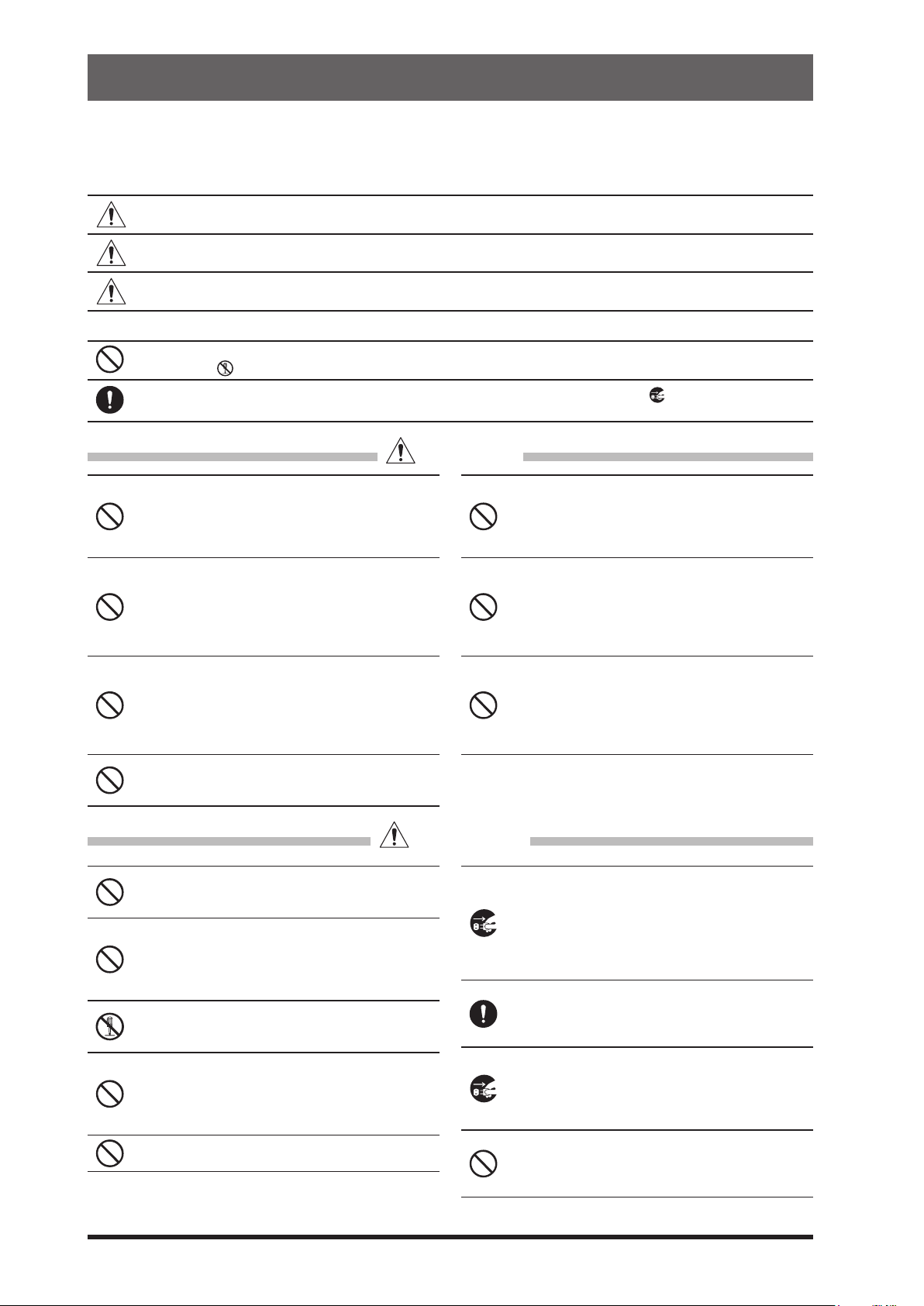
Type and meaning of the marks
DANGER
WARNING
CAUTION
Type and meaning of symbols
Prohibited actions that must not be attempted, in order to use this radio safely.
For example,
Precautions that must be adhered to in order to use this radio safely. For example, signifies that the power
supply is to be disconnected.
Do not use the device in “regions or aircrafts
and vehicles where its use is prohibited” such
as in hospitals and airplanes.
This may exert an impact on electronic and medical devices.
Do not use this product while driving or riding
a motorbike. This may result in accidents.
Make sure to stop the car in a safe location first
before use if the device is going to be used by
the driver.
Do not transmit in crowded places in consideration of people who are fitted with medical
devices such as heart pacemakers.
Electromagnetic waves from the device may affect the medical device, resulting in accidents
caused by malfunctions.
Never touch the antenna during transmission.
This may result in injury, electric shock and equipment failure.
This mark indicates an imminently hazardous situation, which, if not avoided, could result in
death or serious injury.
This mark indicates a potentially hazardous situation, which, if not avoided, could result in
death or serious injury.
This mark indicates a potentially hazardous situation, which, if not avoided, may result in minor
or moderate injury or only property damage.
signifies that disassembly is prohibited.
DANGER
Do not operate the device when flammable
gas is generated.
Doing so may result in fire and explosion.
When an alarm goes off with the external antenna connected, cut off the power supply to
this radio immediately and disconnect the external antenna from this radio.
If not, this may result in fire, electric shock and
equipment failure due to thunder.
Do not touch any liquid leaking from the liquid
display with your bare hands.
There is a risk of chemical burns occurring when
the liquid comes into contact with the skin or gets
into the eyes. In this case, seek medical treatment immediately.
Do not use voltages other than the specified
power supply voltage.
Doing so may result in fire and electric shock.
Do not transmit continuously for long periods
of time.
This may cause the temperature of the main body
to rise and result in burns and failures due to
overheating.
Do not dismantle or modify the device.
This may result in injury, electric shock and equipment failure.
Do not handle the power plug and connector
etc. with wet hands. Also do not plug and unplug the power plug with wet hands.
This may result in injury, liquid leak, electric shock
and equipment failure.
Do not use fuses other than those specified.
Doing so may result in fire and equipment failure.
6
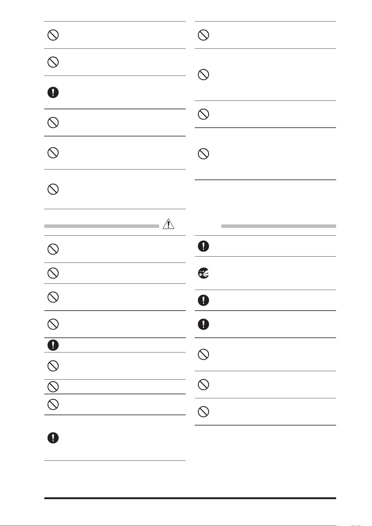
WARNING
When smoke or strange odors are emitted
from the radio, turn off the power and disconnect the power cord from the socket.
This may result in fire, liquid leak, overheating,
damage, ignition and equipment failure. Please
contact our company customer support or the retail store where you purchased the device.
Keep the power plug pins and the surrounding areas clean at all times.
This may result in fire, liquid leak, overheating,
breakage, ignition etc.
Disconnect the power cord and connection
cables before incorporating items sold separately and replacing the fuse.
This may result in fire, electric shock and equipment failure.
Never cut off the fuse holder of the DC power
cord.
This may cause short-circuiting and result in ignition and fire.
Page 9
Do not allow metallic objects such as wires
and water to get inside the product.
This may result in fire, electric shock and equipment failure.
Do not place the device in areas that may get
wet easily (e.g. near a humidifier).
This may result in fire, electric shock and equipment failure.
When connecting a DC power cord, pay due
care not to mix up the positive and negative
polarities.
This may result in fire, electric shock and equipment failure.
Do not use DC power cords other than the one
enclosed or specified.
This may result in fire, electric shock and equipment failure.
Do not bend, twist, pull, heat and modify the
power cord and connection cables in an unreasonable manner.
This may cut or damage the cables and result in
fire, electric shock and equipment failure.
Do not pull the cable when plugging and unplugging the power cord and connection cables.
Please hold the plug or connector when unplugging. If not, this may result in fire, electric shock
and equipment failure.
Refrain from using headphones and earphones at a loud volume.
Continuous exposure to loud volumes may result
in hearing impairment.
Do not use the device when the power cord
and connection cables are damaged, and
when the DC power connector cannot be
plugged in tightly.
Please contact our company customer support or
the retail store where you purchased the device
as this may result in fire, electric shock and equipment failure.
Follow the instructions given when installing
items sold separately and replacing the fuse.
This may result in fire, electric shock and equipment failure.
Do not use the device when the alarm goes
off.
For safety reasons, please pull the power plug of
the DC power equipment connected to the product out of the AC socket.
Never touch the antenna as well. This may result
in fire, electric shock and equipment failure due
to thunder.
CAUTION
Do not place this device near a heating instrument or in a location exposed to direct sunlight.
This may result in deformation and discoloration.
Do not place this device in a location where
there is a lot of dust and humidity.
Doing so may result in fire and equipment failure.
Stay as far away from the antenna as possible
during transmission.
Long-term exposure to electromagnetic radiation
may have a negative effect on the human body.
Do not wipe the case using thinner and benzene etc.
Please use a soft and dry piece of cloth to wipe
away the stains on the case.
Keep out of the reach of small children.
If not, this may result in injuries to children.
Do not put heavy objects on top of the power
cord and connection cables.
This may damage the power cord and connection
cables, resulting in fire and electric shock.
Do not transmit near the television and radio.
This may result in electromagnetic interference.
Do not use optional products other than those
specified by our company.
If not, this may result in equipment failure.
When using the device in a hybrid car or fuel-saving car, make sure to check with the car
manufacturer before using.
The device may not be able to receive transmissions normally due to the influence of noises from
the electrical devices (inverters etc.) fitted in the
car.
Do not turn on the volume too high when using a headphone or earphone.
This may result in hearing impairment.
For safety reasons, switch off the power and
pull out the DC power cord connected to the
DC power connector when the device is not
going to be used for a long period of time.
If not, this may result in fire and overheating.
Do not throw or subject the device to strong
impact forces.
This may result in equipment failure.
Do not the put this device near magnetic cards
and video tapes.
The data in the cash card and video tape etc. may
be erased.
Do not place the device on an unsteady or
sloping surface, or in a location where there
is a lot of vibration.
The device may fall over or drop, resulting in fire,
injury and equipment failure.
Do not stand on top of the product, and do not
place heavy objects on top or insert objects
inside it.
If not, this may result in equipment failure.
Do not use a microphone other than those
specified when connecting a microphone to
the device.
If not, this may result in equipment failure.
7
Page 10
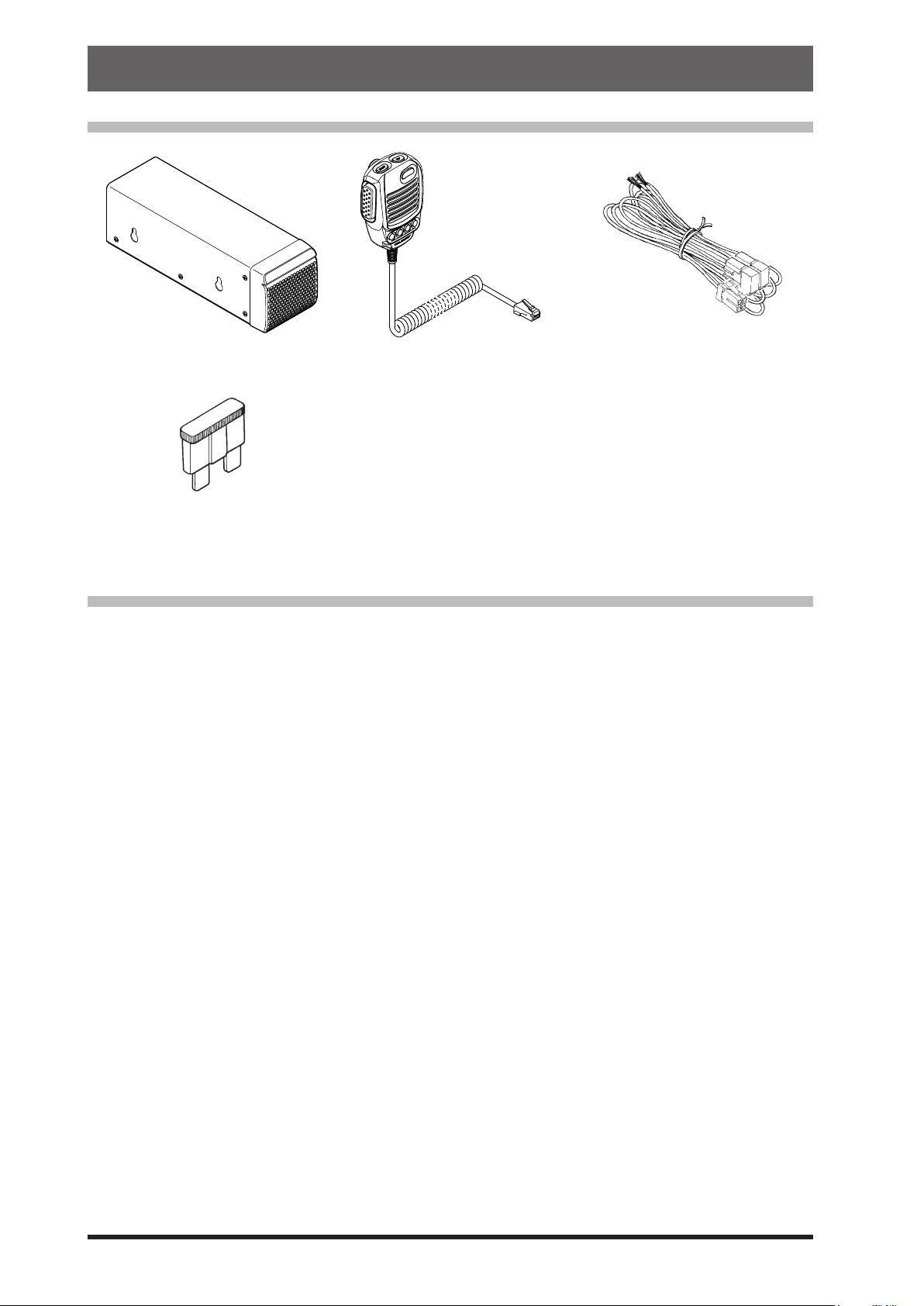
Accessories & Options
Supplied Accessories
External Speaker SP-40 Hand Microphone SSM-75E DC Power Cord
Spare Fuse (25A)
• Operation Manual • World Map • Sticker
Available options
• Hand Microphone (equivalent to the supplied microphone) SSM-75E
• Reference Microphone M-1
• Dual Element Microphone M-100
• Desktop Microphone M-90D
• Microphone Stand Kit M-90MS
• Desktop Microphone M-70D
• Lightweight Stereo Headphone YH-77STA
• External Automatic Antenna Tuner FC-40
• Active Tuning Antenna (Automatic Type) ATAS-120A
• Antenna Base Kit (for ATAS-120A) ATBK-100
• Active Tuning Antenna (Manual Type) ATAS-25
• Remote Control Keypad FH-2
• LAN Unit SCU-LAN10
• Mounting Bracket SMB-209
• Carrying Handle MHG-1
• Packet Cable CT-39A
• VL-1000 Linear Amplier Connection Cable CT-58
8
Page 11
Installation and Interconnections
Check the DC voltage and current rating
DC power cord (supplied)
Antenna Considerations
The FT-710 is designed to connect to a 50 Ohm resistive impedance antenna at the Amateur operating
frequencies. Select an appropriate antenna (dipole antenna, YAGI antenna, cubical quad antenna, etc.)
that is suitable for the chosen operation and bands.
Construct the antenna and coaxial cable, or use a suitable antenna tuner, to maintain the impedance
presented to the FT-710 antenna connector for an SWR of 1.5 or less. Careful preparation of the antenna
and/or tuner will permit maximum performance, and protect the transceiver from damage.
High transmitter RF voltages may be present on the antenna; install it so it will not be easily touched when
in operation.
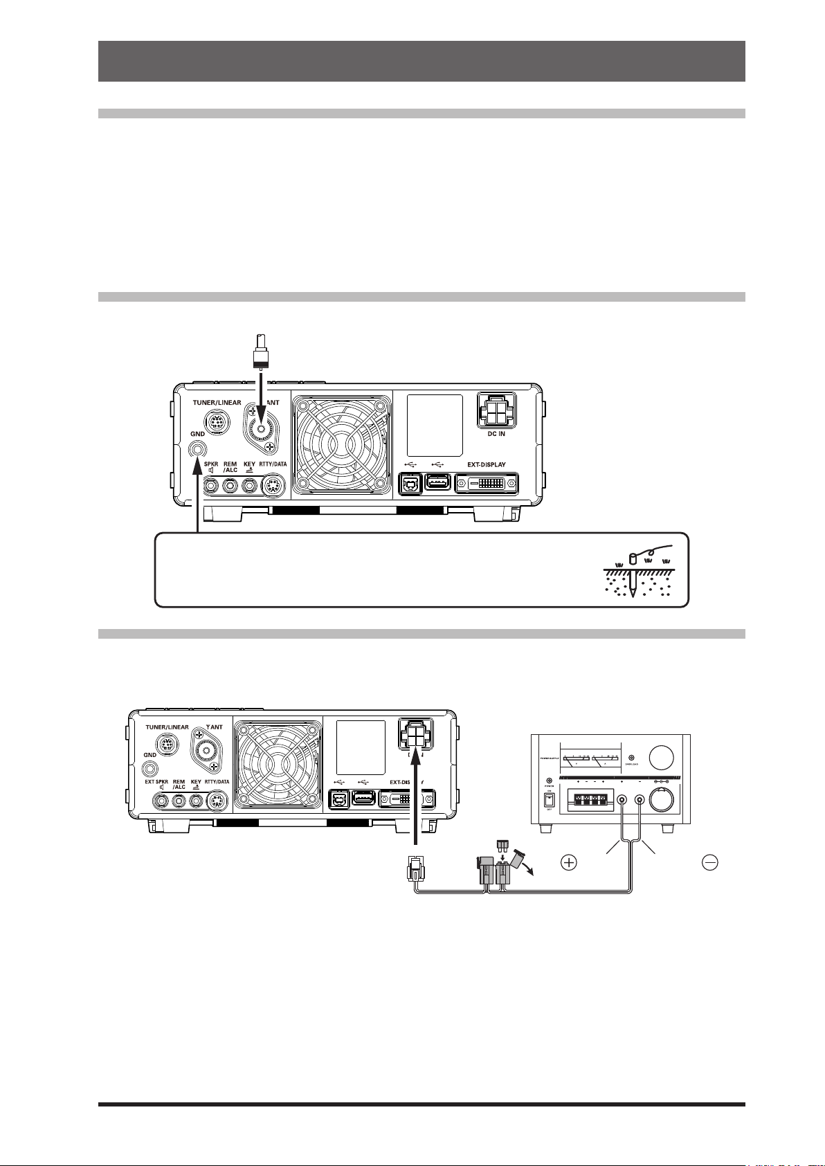
Antenna Connections
Carefully follow the illustration regarding the proper connection of antennas and coaxial cables.
To prevent damage from lightning, atmospheric electrical discharges,
electric shock etc., provide a good earth ground.
Use a short, thick, braided cable to connect the station equipment to the
buried ground rod (or alternative earth ground system).
Power Cable Connections
Carefully follow the illustrations regarding the proper connection of the DC power cable.
Use the DC power cable supplied with the FT-710 to make the power connections to the power supply.
(+13.8 V, 25 A) of the power supply before
connecting to the transceiver.
FUSE: 25A
BLACK
Installation guidelines
• Ensure adequate ventilation around the transceiver, to prevent heat build-up and possible reduction of performance due over heating.
• Do not install the transceiver in a mechanically
unstable location, or where objects may fall onto
it from above.
• To minimize the possibility of interference to
home entertainment devices, take all precautionary steps including separation of TV/FM anten-
RED
nas from Amateur transmitting antennas to the
greatest extent possible. Keep the transmitting
coaxial cables separated from cables connected
to home entertainment devices.
• The AC Power Cord connected to a socket-outlet with earthing connection. A socket-outlet with
earthing connection shall connect to protective
earthing conductor.
9
Page 12
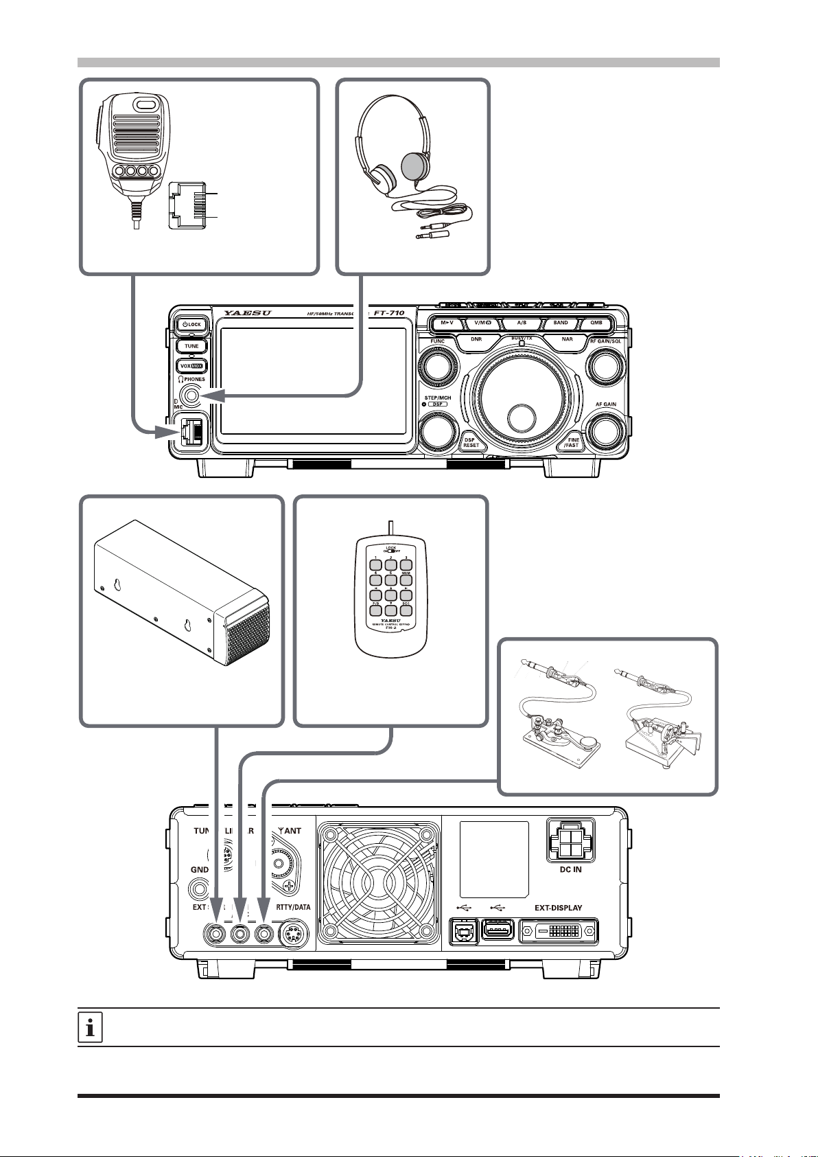
Microphone, Headphone, Key, Keyer and FH-2 Connections
DOWN
①
UP
②
+5V
③
MIC GND
④
MIC
⑤
①
PTT
⑥
GND
⑦
⑧
FAST
⑧
(as viewed from front panel)
φ3.5mm
External Speaker
SP-40
Remote Control Keypad
FH-2 (option)
Key-up voltage is approximately +5.0V DC, and key-down current is approximately 3mA.
10
Page 13
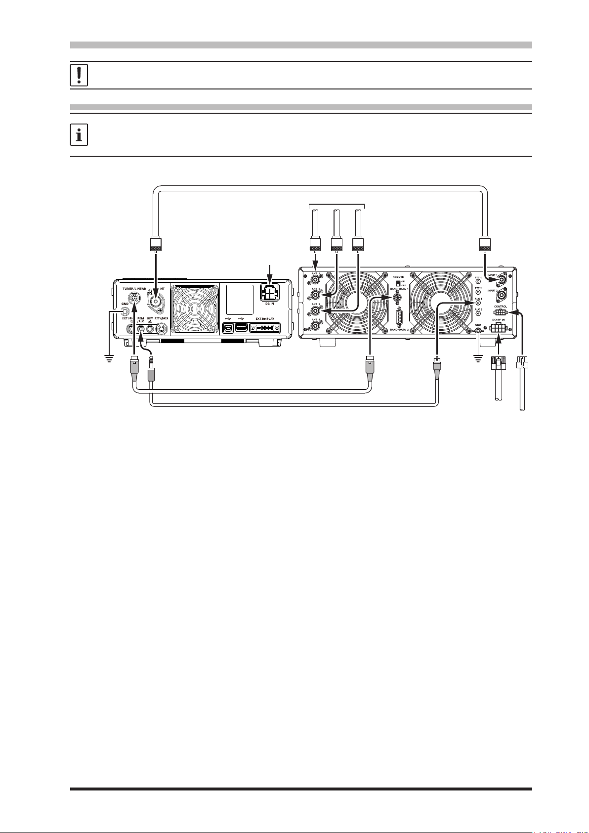
Linear Amplier Interconnections
CONTROL
Coaxial Cable (50 ohm)
TUNER/LINEAR
Be sure that both the FT-710 and VL-1000 are turned OFF, and then follow the installation recommendations
contained in the bellow illustration.
• VL-1000 Linear Amplier Interconnections
• Refer to the VL-1000 Operating Manual for details regarding amplier operation.
• Do not attempt to connect or disconnect coaxial cables when your hands are wet.
• Set the Setting Menu item “TUN/LIN PORT SELECT” to “LINEAR” (page 89).
• Since the ALC cable is connected to the REM/ALC jack, the optional FH-2 cannot be connected.
Connect to “INPUT 1” of the VL-1000
HF/50MHz Antenna
GND
ANT
REM/ALC
DC IN
“CT-58” Band Data Cable (option)
“CT-58” ALC Cable (option)
ANT 1
ANT 2
ANT 3
INPUT 1
ALC 1BAND-DATA 1
GND
DC 48V IN
11
Page 14

Display connections
Internet
The video digital output of the FT-710 transceiver can be shown on a large monitor. Use a commercially
available DVI-D cable to connect a display monitor directly to the “EXT-DISPLAY” terminal (DVI-D) on the
back of the FT-710.
The DVI-D cable can be used with either single link or dual link.
EXT-DISPLAY
DVI-D Cable
DVI-D
Remote operation (LAN unit “SCU-LAN10”) connection
Operate the transceiver from a remote location. Use the optional LAN unit “SCU-LAN10” to connect
the FT-710 to a LAN or the Internet, then use the PC control software that can be downloaded from the
Yaesu website. In addition to the basic remote operation of the transceiver, the LAN unit supports monitoring the various scope displays, so you can operate comfortably. In addition to remote operation from a
remote location, you can connect to your home LAN and monitor the band status on a large display from
a convenient location away from the ham shack.
In addition to transmitted and received audio, the RF scope and AF scope can be remoted, so comfortable remote communication can be performed while easily setting and tuning the band status display,
making various lter settings, interference removal function, etc. are possible using the scope function
from a personal computer.
or
Remote control
SCU-LAN10
(option)
LAN Network
LAN
Remote control PC
12
DC-IN
LAN
Page 15
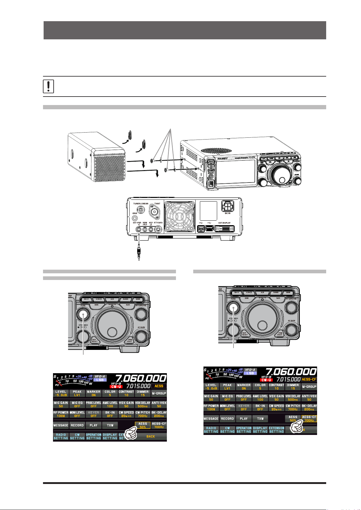
AESS
Supplied washers and screws
FUNC knob
FUNC knob
The combination of the internal speaker on top of the transceiver with the external speaker
“SP-40”, reproduces high-quality received audio with a wide frequency range and a three-dimensional
acoustic eect. Set the optimum sound quality by adjusting the output balance and frequency characteristics of the two speakers according to your preference.
• The AESS is designed to function optimally with the included speaker “SP-40”. It will not perform properly
with other speakers.
• When moving or transporting the FT-710, remove the SP-40 to prevent it from falling o.
(Acoustic Enhanced Speaker System)
SP-40 connections
The SP-40 can be mounted on either the left or right side of the transceiver.
remove
Connect the speaker cable to the
“EXT SPKR” terminal on the rear panel.
• Change the output balance of the
two speakers
1. Press the [FUNC] knob.
2. Touch [AESS].
• Change the frequency characteristics
1. Press the [FUNC] knob.
2. Touch [AESS-CF].
3. Rotate the [FUNC] knob to adjust the output
balance of the two speakers, according to
your liking. It is recommended to use it at
around 50%.
3. Rotate the [FUNC] knob to select the cutoff
frequency from “700Hz” and “1000Hz”.
Normally, 700Hz is a balanced sound quality,
but when listening at a loud volume, set it to
1000Hz.
13
Page 16
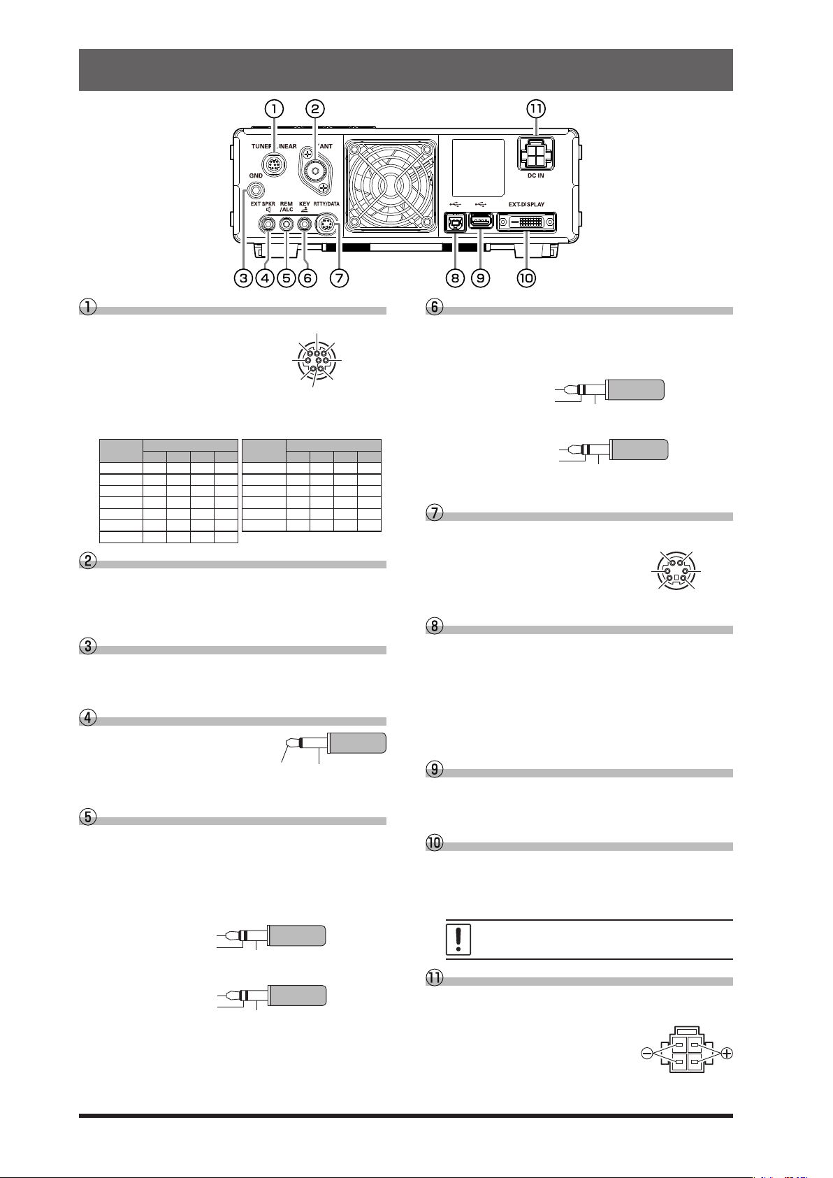
Rear Panel
GND
REMOTE
GND
SIGNAL GND
GND
COMMON
DATA IN
GND
DATA OUT SQL
RESET(BAND D)
RX D(BAND B)
TX D(BAND A)
+13V OUT
TUNER/LINEAR
This 8-pin output
jack is used to connect to the FC-40
External Automatic
Antenna Tuner or a
Linear Amplier.
Refer to the table below for the BAND DATA termi-
nal levels when using a linear amplier.
BAND
400k H L H H 18 L H H L
1 L H H H 21 H H H L
1.8 H L L L 24.5 L L L H
3.5 L H L L 28 H L L H
5 / 7 H H L L 50 L H L H
10 L L H H 70 H H H H
14 H L H L
ANT
Connect the main antenna here, using type-M (PL-
259) connectors and coaxial feed lines. The internal
antenna tuner aects only the antenna connected
here, and only during transmission.
GND
Use this terminal to connect the transceiver to a
good earth ground, for safety and optimal performance.
EXT SPKR
This 3.5-mm, 2-contact, jack
provides audio output for a
external loudspeaker “SP40”. The impedance at the
jack is 4-8 Ohms.
REM/ALC
By plugging the FH-2 Remote Control Keypad into
this jack, direct access to the FT-710 CPU is provided for control functions of the contest memory
keying, and also frequency and function control.
When a device such as a linear amplifier is connected, this is an external ALC current input jack.
BAND DATA
A B C D A B C D
TX INH BAND C
GND
TX GND
BAND
BAND DATA
KEY
This 3.5-mm, 3-contact jack accepts a CW key or
keyer paddle. A two-contact plug cannot be used
in this jack. Key-up voltage is +5.0V DC, and keydown current is 3mA.
KEY
NC
When connecting a single straight key
DOT
DASH
When connecting an electronic keyer paddle
RTTY/DATA
This 6-pin input/output jack accepts AFSK input
from a Terminal Node
Controller (TNC); it also
provides xed level receiver audio output, and FSK
keying line.
USB
Connecting to a computer from this jack with a
commercially available USB cable allows remote
control by CAT commands from a computer. The
jack can also be used for input and output of audio
signals and transmitter control. A USB driver is required for remote control from a computer. Download the driver from the Yaesu website (http://www.
yaesu.com).
USB Jack
Connect a USB A type keyboard or mouse. They
can be used to select items on the screen or to enter characters.
EXT-DISPLAY
DVI-D connector for connecting an external monitor.
When using an external monitor, set the setting
menu item “EXT DISPLAY” to “ON”.
PTT SHIFT
14
EXT ALC
TX REQ
Set menu item “TUN/LIN PORT SELECT” to “LINEAR”.
NC
Set menu item “TUN/LIN PORT SELECT” to other than
“LINEAR”.
Connect a monitor that supports 800 x 480
resolution or 800 x 600 resolution.
DC IN
This is the DC power supply connection for the
transceiver.
Use the supplied DC cable to
connect directly to a DC power
supply, which must be capable
of supplying at least 25 A @13.8
VDC.
Page 17
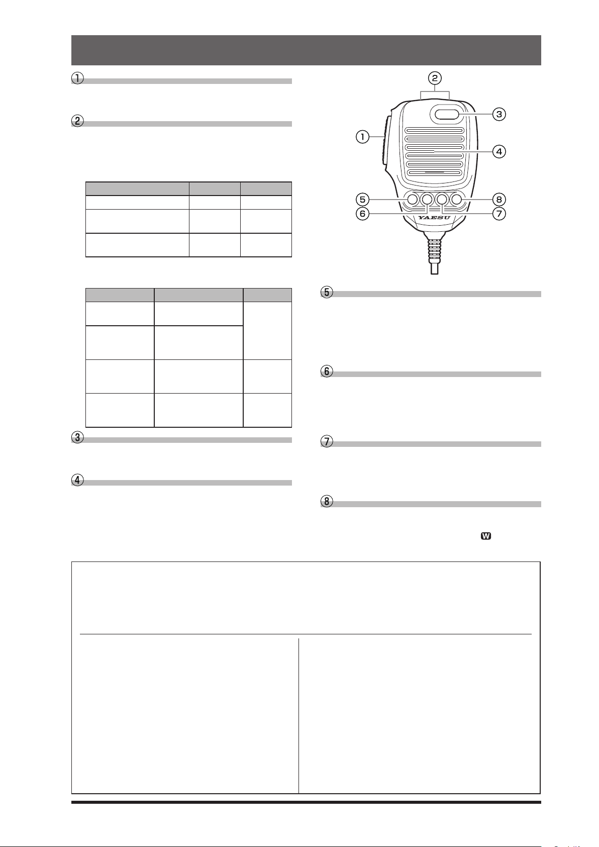
SSM-75E Microphone Switches
PTT Switch
Switches Transmit/Receive.
Press to transmit and release to receive.
DWN / UP Key
The [UP]/[DWN] keys may also be used to manually scan the frequency upward or downward.
● The amount of frequency change depends on the
operation mode (default setting: see table below).
MUTE
Operating Mode UP DWN
LSB / USB / CW-L / CW-U +20
DATA-L / DATA-U
RTTY-L / RTTY-U / PSK
AM / AM-N / FM / FM-N
DATA-FM / D-FM-N
● The frequency change can be changed in the
setting menu.
Operating Mode Menu Item Step
LSB / USB
CW-L / CW-U
DATA-L / DATA-U
RTTY-L / RTTY-U
PSK
AM / AM-N AM CH STEP
FM / FM-N
DATA-FM
D-FM-N
MUTE Key
While pressing the MUTE key, the receiver audio
from the speaker will be muted.
Microphone
Speak into the microphone in a normal tone of
voice with the microphone 5cm away from the
mouth.
SSB/CW DIAL STEP
RTTY/PSK DIAL STEP
FM CH STEP
Hz
+10Hz
+5kHz -5kHz
-20Hz
-10Hz
5/10/20 (Hz)
2.5/5/9/10/
12.5/25
(kHz)
5/6.25/10/
12.5/20/25
(kHz)
P1 P2 P3 P4
P1 key
This key toggles the ON/OFF lock for the MAIN Dial
knob. When “Lock” is ON, the MAIN Dial knob can
still be turned, but the frequency will not change,
and “LOCK” appears in the display.
It is the same function as the [LOCK] key on the
front panel of the transceiver.
P2 key
The current operation status can be stored in a
dedicated memory channel (QMB: Quick Memory
Bank) with one touch.
It is the same function as the [QMB] key on the
front panel of the transceiver.
P3 key
Pressing this key momentarily, exchanges the
VFO-A and VFO-B frequency data.
It is the same function as the [A/B] key on the front
panel of the transceiver.
P4 key
This key toggles frequency control between VFO
and the memory system.
It is the same function as the [V/M
front panel of the transceiver.
] key on the
The functions of the [P1] / [P2] / [P3] / [P4] / [UP] / [DWN] keys can be assigned by the following operations:
1. Press the [FUNC] knob.
2. Select [OPERATION SETTING] → [GENERAL].
3. Select a key to assign a function [MIC P1] / [MIC P2] / [MIC P3] / [MIC P4] / [MIC UP] / [MIC DOWN].
4. Rotate the [FUNC] knob, or touch “<” or “>” on either side of the value to select a function (see the table below)
5. Touch [BACK] several times to return to normal operation.
LOCK
QMB
A/B
V/M
TUNER
VOX/MOX
MODE
ZIN SPOT
SPLIT
: Toggles the ON/OFF lock for the MAIN
Dial knob.
: QMB (Quick Memory Bank) function.
: Swaps the VFO-A and VFO-B frequency
data.
: Toggles frequency control between VFO
and the memory system.
:
Turns the built-in antenna tuner ON/OFF
: Press to turn the VOX function ON/OFF.
Press and hold to activate the MOX
function.
: Change the operation mode.
: Press to activate the auto-zero function.
Press and hold to activate the sidetone.
: SPLIT function.
FINE
NAR
NB
DNR
FREQ UP
FREQ DOWN
.
BAND UP
BAND DOWN
ATT
IPO
DNF
AGC
: Sets the ne tuning ON/OFF.
: Sets the Narrow ON/OFF.
: Activates the NB (Noise blanker) func-
tion.
: Activates the DNR (Digital Noise Reduc-
tion) function.
: Change to a higher frequency.
: Change to a Lower frequency.
: Change to a higher Operation Band.
: Change to a Lower Operation Band.
: Turns the ATT (Attenuator) ON/OFF.
: Activates the IPO.
: Turns the DNF (Digital Notch Filter) ON/
OFF.
: Adjust the AGC receiver-recovery time.
.
15
Page 18
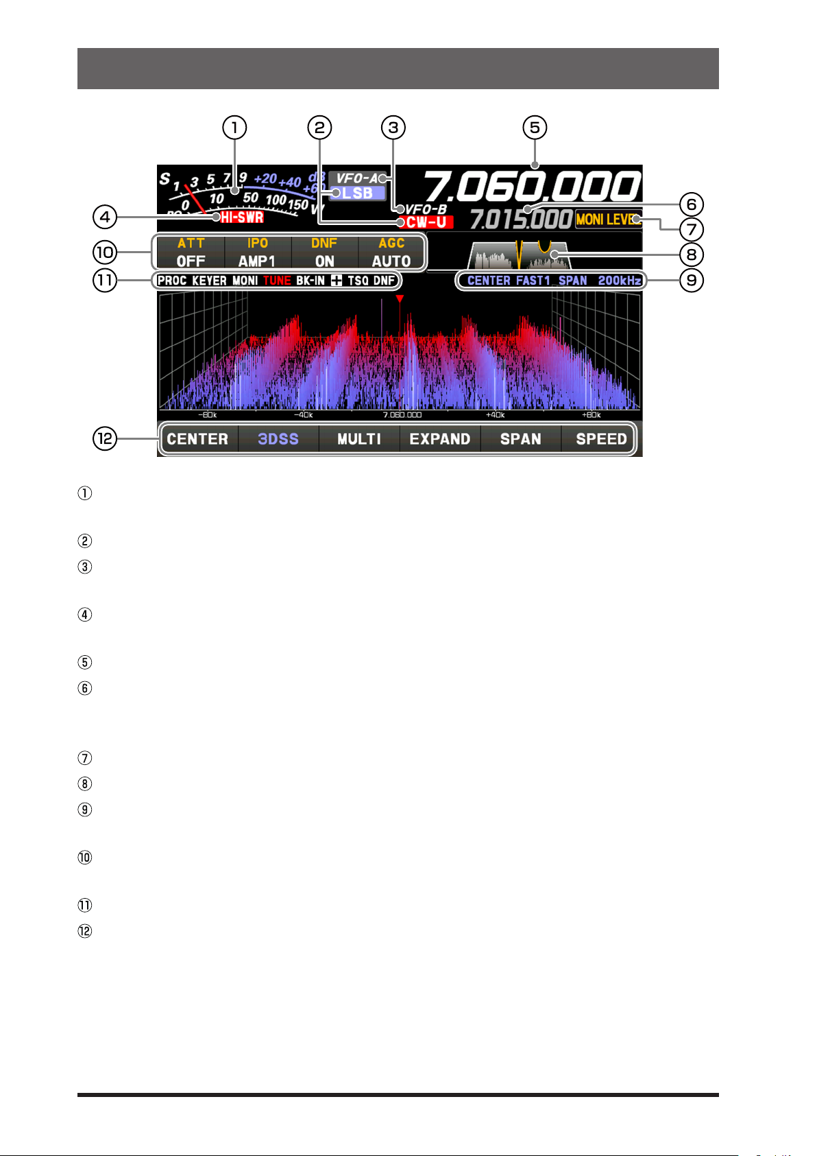
Display Indications
It operates as an S meter in receive. In transmit, select the desired meter from: PO,
COMP, ALC, VDD, ID, and SWR.
Displays the current operation mode.
In VFO mode, “VFO-A” or “VFO-B” is displayed. In memory mode, the type and chan-
nel number of the recalled memory are displayed.
This display warns of an abnormality in the antenna system. If it lights up, check the
antenna system immediately.
Displays the transmit/receive frequency of Main-band.
Displays the transmit/receive frequency of Sub-band. While the clarifier function is
operating, the oset (dierence between the receive frequency and the transmit frequency) is displayed.
The functions that operate when the [FUNC] knob is turned are displayed.
Displays the passband status of the Digital lter.
Displays the mode, the sweep speed, and span width (display range) of the scope
screen.
Displays the setting status of assorted important receiver operations. The setting can
be changed by touching it.
The icon of the operating function lights up.
Touch the scope screen keys to switch the display mode of the screen between the
3DSS display and waterfall display, to display the oscilloscope and AF-FFT, to switch
the display area of the scope screen, to set the frequency span (display range), or to
switch the sweep speed.
16
Page 19
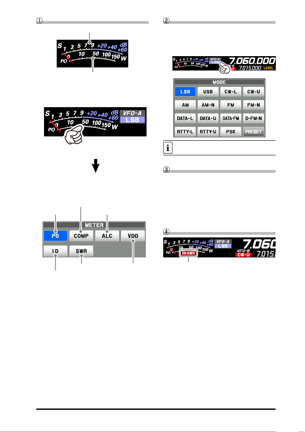
Meter Display
S-Meter
RF power Output
Final amplifier drain current
AMC gain control display
(Displays compression level during
speech processor operation)
Make adjustments by pressing the [FUNC] knob
→
abnormality in the antenna system.
When the meter display screen is touched, the
transmit meter selection screen is shown (the
default setting is “PO”).
Operation MODE Display
Displays the current operating mode. When
touched the operation mode selection screen is
displayed. Touch the desired operation mode to
select it.
Touch the meter area
touch [COMP] → rotate the [FUNC] knob.
RF power Output
Standing Wave Ratio Final amplifier
Relative ALC voltage
drain voltage
→
Touch [PRESET] to display the settings that apply to the FT8 operation.
Operation status Display
VFO-A: Lights in VFO-A mode.
VFO-B: Lights in VFO-B mode.
M-xx: Displays the selected channel number in
MT: Lights up during memory tuning operation.
QMBxx: Lights up during operation with quick memory.
M-Pxx: Lights up during programmable memory scan
EMG: Emergency call set frequency call lights up.
memory mode.
operation.
HI-SWR Display
This is a warning notification of an
If “HI-SWR” lights up, immediately check if for
any abnormality in the antenna system.
17
Page 20
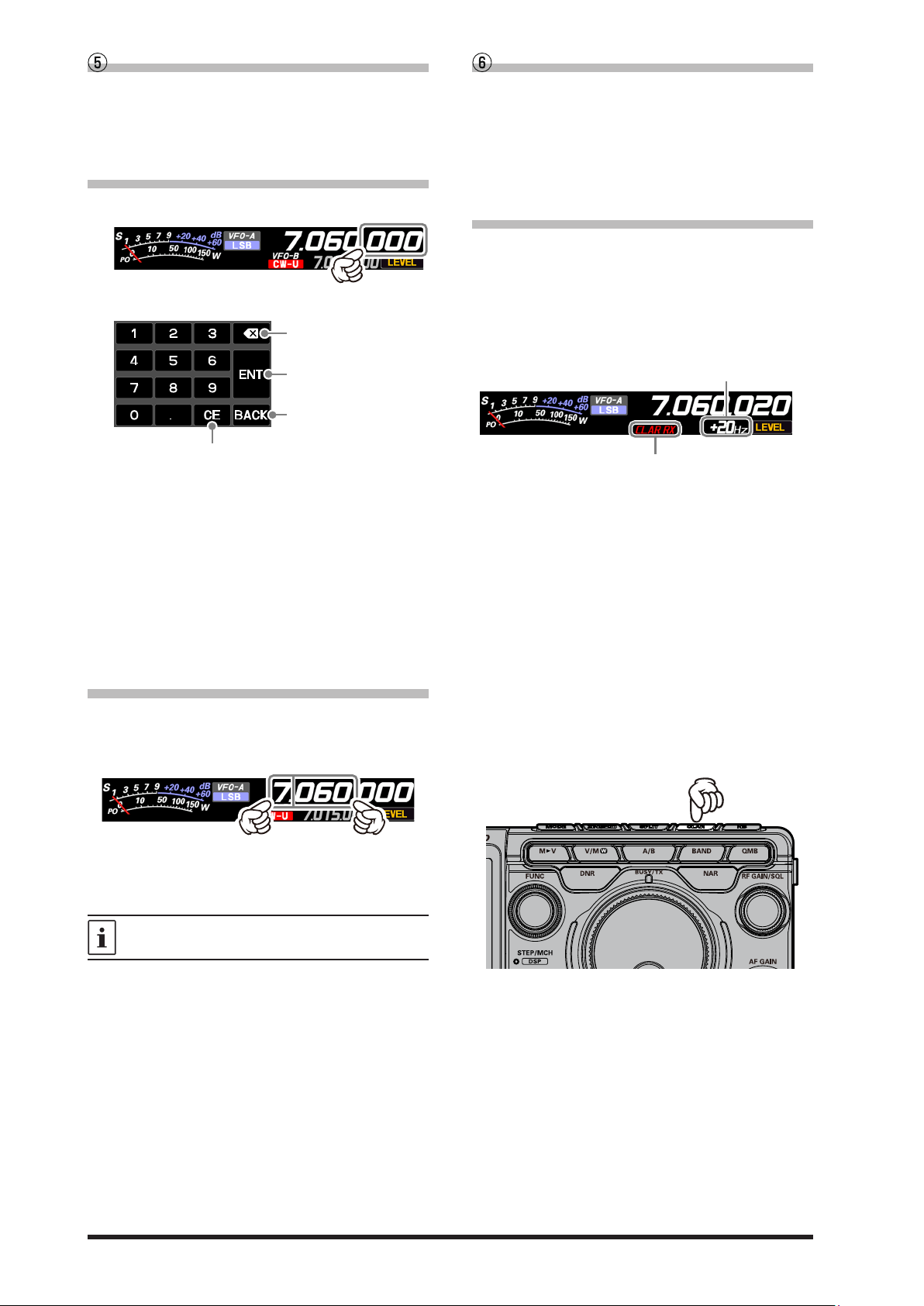
Frequency Display (VFO-A)
Clear all entered numbers.
CLAR RX
CLAR TX
CLAR RXTX
•
will set the transmit frequency to match the
transmit frequency.
When the receive frequency is offset by +20 Hz.
Frequency Display (VFO-B)
Displays the transmit and receive frequencies of
VFO-A. Press the [A/B] key to switch between
VFO-A and VFO-B, the frequency of VFO-B is
displayed.
• Keyboard Frequency Entry
1. Touch the “Hz” area of the frequency display.
2. Enter the frequency using the numeric keys.
Erases the rightmost digit.
The entered frequency is
confirmed.
The display returns to the
previous screen when
back is touched.
● If there is no operation within 10 seconds,
the input will be canceled.
3. Touch [ENT] to conrm.
● A short-cut for frequencies ending in zero -
touch [ENT] after the last non-zero digit.
Example:
To enter 7.00.000MHz
[0] → [7] → [ENT] or [7] → [.] → [ENT]
To enter 7.03.000MHz
[7] → [.] → [0] → [3] → [ENT]
• Tuning in 1 MHz or 1 kHz Steps
To temporarily set the dial knob to 1MHz or 1kHz
steps, touch the “MHz” or “kHz” area of the frequency display.
Displays the transmit and receive frequencies of
VFO-B. Press the [A/B] key to switch between
VFO-B and VFO-A, the frequency of VFO-A is
displayed.
When the clarier function is active, the oset frequency is displayed.
• When the clarier function is active
The clarier is used to adjust the transceiver receive frequency to match the other station transmit frequency and improve the audio; or to shift
the transmit frequency of this station when the
transmit frequency of the contact station is shifted.
:
Changes only the receive frequency while
leaving the transmit frequency as it is.
:
Changes only the transmit frequency while
leaving the receive frequency as it is.
: •
After changing the receive frequency with
the clarifier, pressing the [CLAR] key twice
receive frequency.
After changing the transmit frequency with
the clarifier, pressing the [CLAR] key will
set the receive frequency to match the
Press the [CLAR] key, the display will show “CLAR
RX” in red and the clarier will be active.
Rotate the DIAL knob to change the offset fre-
quency of the clarier.
To cancel Clarifier operation, press the [CLAR]
key several times.
Touch “MHz” or “kHz” area of the frequency display to confirm. If there is no operation within 3
seconds, the frequency will be xed.
Touch the Scope Screen, to easily move to the
touched frequency.
18
Page 21
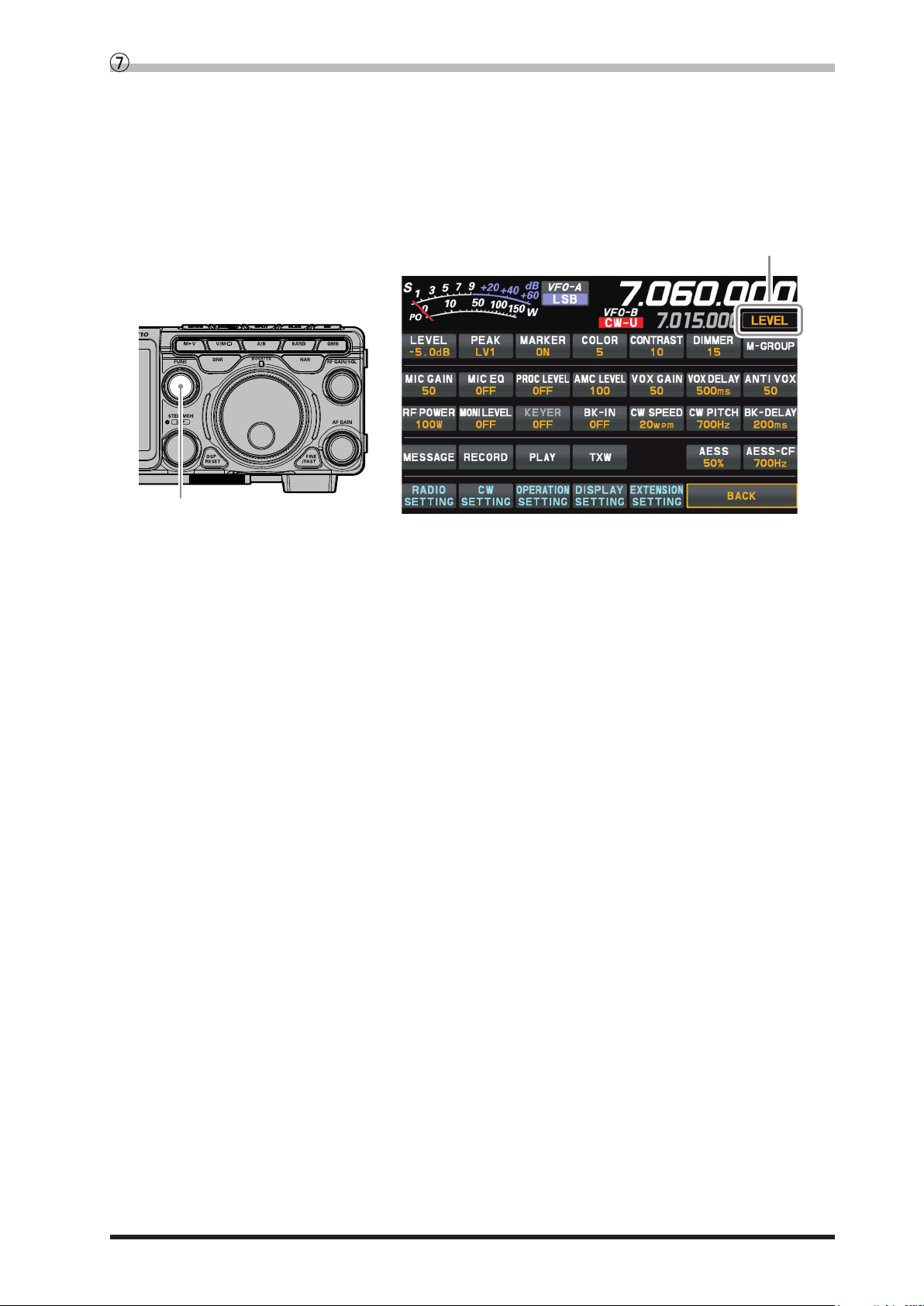
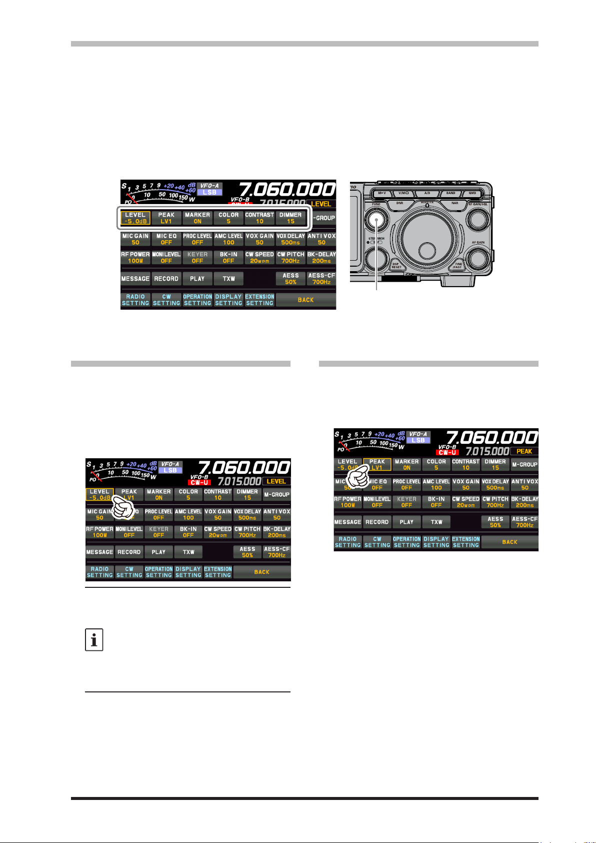
Operation of the display [FUNC] knob
FUNC knob
Operation of the FUNC knob
Displays the multiple functions that may be operated when the [FUNC] knob is pressed.
Normally, it is recommended to adjust the level of the spectrum scope with the [LEVEL] knob.
The last used function is recalled when the [FUNC] knob is pressed. Therefor you can easily call up and
then set a function by turning the [FUNC] knob.
To change the function of the [FUNC] knob, touch the desired item that appears on the function screen
when the [FUNC] knob is pressed, or turn the [FUNC] knob to select an item and then press the [FUNC]
knob.
The following settings and operations can be performed with the [FUNC] control.
LEVEL
PEAK
MARKER
COLOR
CONTRAST
DIMMER
M-GROUP
MIC GAIN
MIC EQ
PROC LEVEL
AMC LEVEL
VOX GAIN
VOX DELAY
ANTI VOX
RF POWER
MONI LEVEL
KEYER
BK-IN
CW SPEED
CW PITCH
BK-DELAY
AESS
AESS-CF
: Adjust the reference level to make it easier to distinguish the scope display target signal
from the noise.
: Adjust the Peak Signal Color Density.
: ON/OFF Marker indicates the transmit and receive frequency position within the Scope
Display image.
: Changes the scope display color.
: Adjust the contrast of the TFT display.
: Adjust the brightness of the TFT display.
: Memory group selection.
: Adjusts the microphone gain.
: Three-Band Parametric Microphone Equalizer is turned ON/OFF.
: Adjusts the Speech Processor Gain.
: Adjusts the AMC (Automatic Microphone Gain Control) Gain.
: VOX gain setting.
: VOX delay setting.
: Anti-VOX Settings.
: Transmit power setting.
: Monitor level adjustment.
: Built-in electronic keyer is turned ON/OFF.
: CW Break-in function is turned ON/OFF.
: Adjusts the desired sending speed.
: Adjusts the CW tone when receiving the CW signal and the side tone monitor.
: Adjust the hang time after the CW transmitting ends.
: Change the output balance of the two speakers.
: Change the frequency characteristics.
19
Page 22
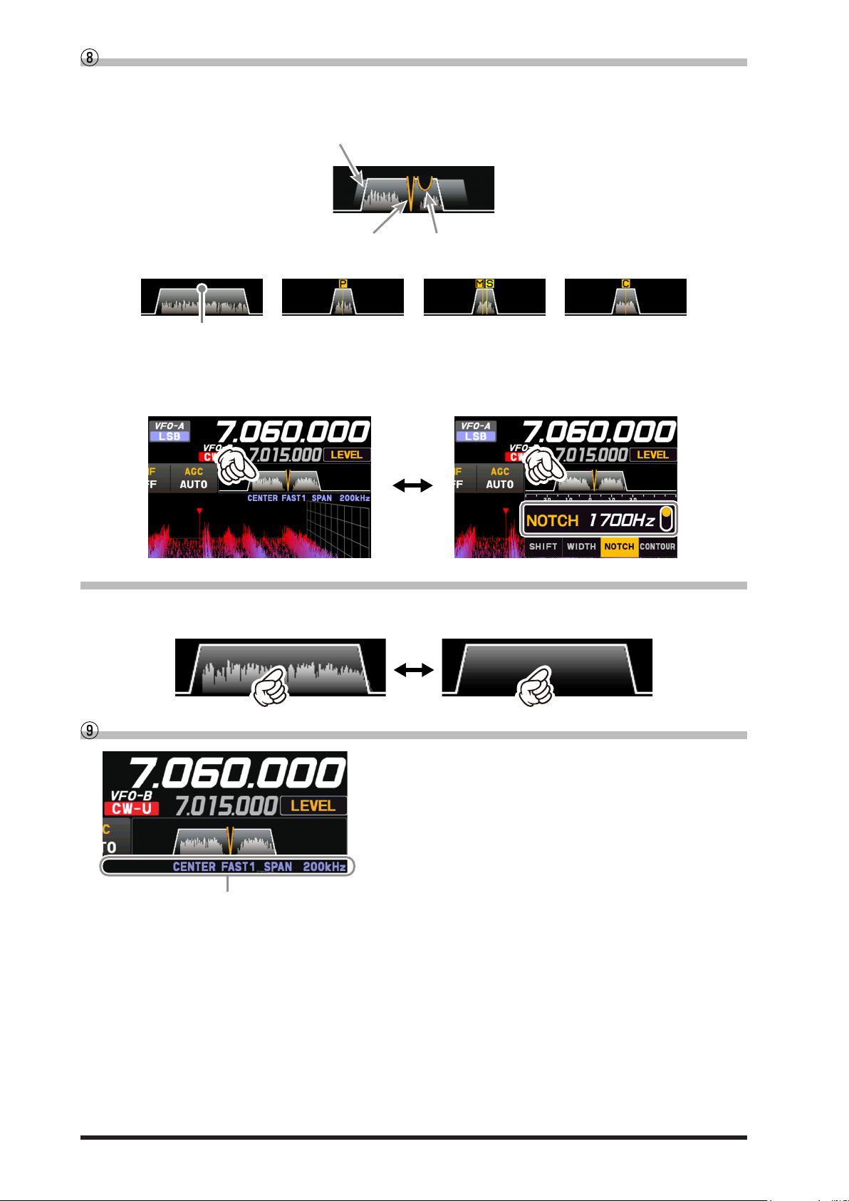
State of CONTOURState of NOTCH
Passband status of DSP filter
SSB Mode CW Mode
DSP filter bandwidth
RTTY Mode PSK/DATA Mode
Filter Function Display
Displays the passband status of the Digital lter. The operation of WIDTH, SHIFT, NOTCH, CONTOUR
etc. can be observed.
(SHIFT, WIDTH)
Touch the lter display to reveal and check the setting value of the last used function from SHIFT, WIDTH, NOTCH,
CONTOUR, and APF. The setting may be changed by turning the [FUNC] knob of the active function.
Example: When the last function used is the NOTCH function
Touch the lter display to display the NOTCH function setting value.
• Turn the spectrum display OFF
To display only the Digital lter bandwidth information, press and hold the spectrum area of the lter function display to clear the spectrum view. To display it, press and hold again.
Information displayed on the scope screen
Scope screen information
CENTER : The receive frequency is always shown at the
center of the screen and spectrum display.
The band spectrum is shown within the range
set by “SPAN”. The CENTER mode is convenient for monitoring the signal activity around
the operating frequency.
CURSOR : Monitors the spectrum within the range set
with “SPAN”. When the frequency (marker)
exceeds the upper limit or the lower limit of
the range, the screen is automatically scrolled
and the status beyond the setting range can
be observed.
FIX : Enter the start frequency of the scope.
SLOW1 : sweep speed Slow
SLOW2 : sweep speed ↑
FAST1 : sweep speed Normal
FAST2 : sweep speed ↓
FAST3 : sweep speed Fast
STOP : Temporarily hold the operation of DSS dis-
play and waterfall display.
SPAN nnnkHz : Scope Screen frequency span (display
range).
20
Page 23
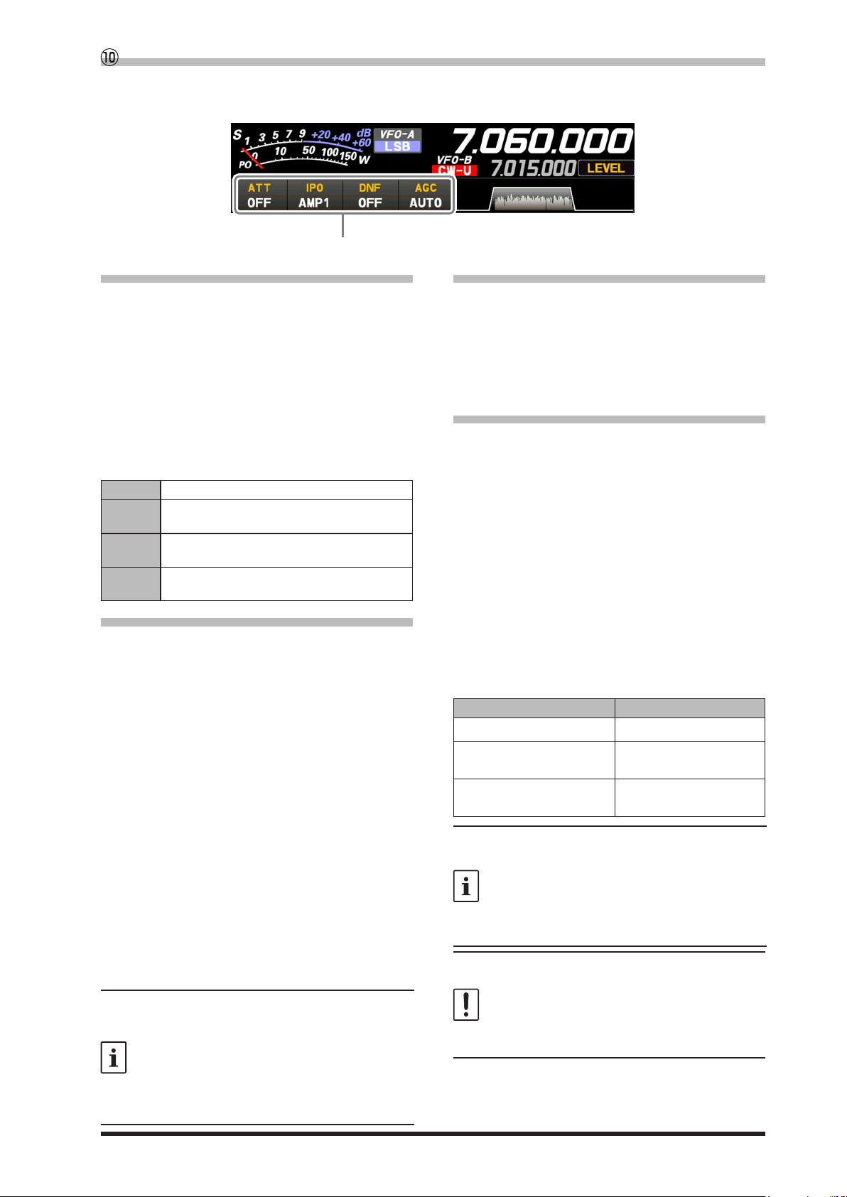
Important Receiver Settings
Important setting items when receiving
The status of various operations that are important during receive, are shown at the bottom of the display.
To change a setting, touch the appropriate location on the display.
• ATT (Attenuator)
Displays the current ATT (Amount of receive input
signal attenuation).
When the desired signal is extremely strong or
the noise level is high on a low frequency band,
activate the attenuator to reduce the incoming
signal or noise from the antenna.
After touching [ATT], touch the desired attenuation amount.
The attenuator is set independently for each operation band.
OFF Attenuator is O
6dB
12dB
18dB
The incoming signal power is reduced by 6dB
(Signal voltage reduced to 1/2)
The incoming signal power is reduced by 12dB
(Signal voltage reduced to 1/4)
The incoming signal power is reduced by 18dB
(Signal voltage reduced to 1/8)
• IPO
The IPO (Intercept Point Optimization) function
can establish the gain of the RF amplier section
to accommodate the connected antenna and the
received signal conditions. IPO can be selected
from three operating conditions.
AMP1: One stage RF amplifier is connected.
This is a well-balanced operation of receiver sensitivity and characteristics (Approximately 10 dB gain).
AMP2: Two RF amplifiers are connected in se-
ries to give top priority to sensitivity (Approximately 20 dB gain).
IPO: The received signal is input to the IF mix-
er without passing through the RF amplifier. This can greatly improve receiving,
especially in the harsh low band signal
environment.
After touching [IPO], touch the desired operating
condition.
• IPO is set independently for each operation
band.
• Normally, select “AMP1”.
• The IPO can not only attenuate the input signal but also improve the intermodulation char-
acteristics. It is most eective to operate the
IPO rst, and then use the ATT if the signal is
still too strong. The noise level can be attenuated and S/N greatly improved.
• DNF (Digital NOTCH Filter)
The Digital NOTCH Filter (DNF) is an effective
beat-canceling filter that can null out a number
of interfering beat notes inside the receiver passband.
Because this is an Auto-Notch feature, there is no
djustment knob associated with this lter.
• AGC (Automatic Gain Control)
Displays the currently selected AGC setting.
The AGC system is designed to help compen-
sate for fading and other propagation eects. The
AGC characteristics can be individually set for
each operating mode. The basic objective of AGC
is to maintain a constant audio output level once
a certain minimum threshold of signal strength is
achieved.
After touching [AGC], touch the desired time constant.
● AGC can be set for each operation band.
● The “AUTO” selection mode selects the opti-
mum receiver-recovery time for the reception
mode.
Operating Mode AUTO AGC Selection
LSB / USB / AM / AM-N SLOW
CW-L / CW-U / FM / FM-N
DATA-FM / D-FM-N
RTTY-L / RTTY-U
DATA-L / DATA-U / PSK
Normally, AGC is set to “AUTO”, which automatically selects the time constant according to
the received signal type, but when receiving a
weak signal or when there is noise and fading,
the AGC action may be changed according to
the reception condition at that time. Change the
time constant to make received signals most
audible
Several aspects of AGC performance may be
configured via the Menu. However, because
AGC can have such a profound impact on overall receiver performance, we generally do not
recommend any changes to the AGC Menu selections until you are thoroughly familiar with the
performance of the FT-710.
FAST
MID
21
Page 24
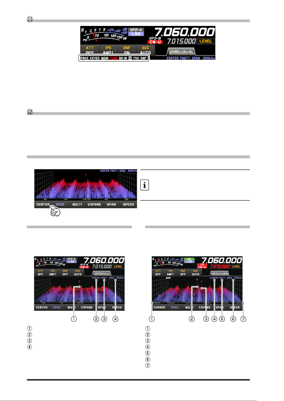
Information displayed on the scope screen
PROC
KEYER
MONI
TUNE
BK-IN
: Lights in plus (+) or negative (-) shift (repeater
: Lights when the Speech function is activated.
: Lights when the Built-in electronic keyer is
activated.
: Lights when the MONITOR function is activated.
: Lights when the internal Automatic Antenna
Tuner is activated. Blinks during tuning.
: Lights when the CW Break-in function is activated.
Scope Display Setting
+/-
operation).
: Lights when the tone encoder is operating.
ENC
: Lights during tone squelch operation.
TSQ
: Lights when the DNF (Digital Notch Filter) is
DNF
activated.
In addition to the conventional two-dimensional waterfall spectrum display, Yaesu has added the 3-Dimension Spectrum Stream (3DSS) color display. The constantly changing band conditions and signals are
depicted in real time and color. The frequency span is shown on the horizontal X axis, the vertical Y axis
depicts the signals and their strengths, and the time is represented on the receding Z axis. The FT-710
operator can intuitively grasp the band and signal conditions at any instant.
• CENTER/CURSOR/FIX
Switches the Spectrum Scope operation each time the key is touched.
• When the display area is touched, the receive
frequency is moved to that point.
• In CENTER mode, the frequency touched becomes the center.
• In CURSOR and FIX mode, the marker and the
receive frequency move to the touched position.
• CENTER
The receive frequency is always shown at the center
of the screen and spectrum display. The band spectrum is shown within the range set by “SPAN”. The
CENTER mode is convenient for monitoring the signal activity around the operating frequency.
Marker*
Current display mode (CENTER)
Sweep Speed
Scope Screen frequency span (display range).
*At factory shipment, marker display is ON.
22
• CURSOR
Monitors the spectrum within the range set with
“SPAN”. When the frequency (marker) exceeds the
upper limit or the lower limit of the range, the screen
is automatically scrolled and the status beyond the
setting range can be observed.
The lower limit frequency of the display area.
Marker* (Receive Frequency)
Marker* (Transmit Frequency)
Current display mode (CURSOR)
Sweep Speed
Scope Screen frequency span (display range).
The upper limit frequency of the display area.
*At factory shipment, marker display is ON.
Page 25
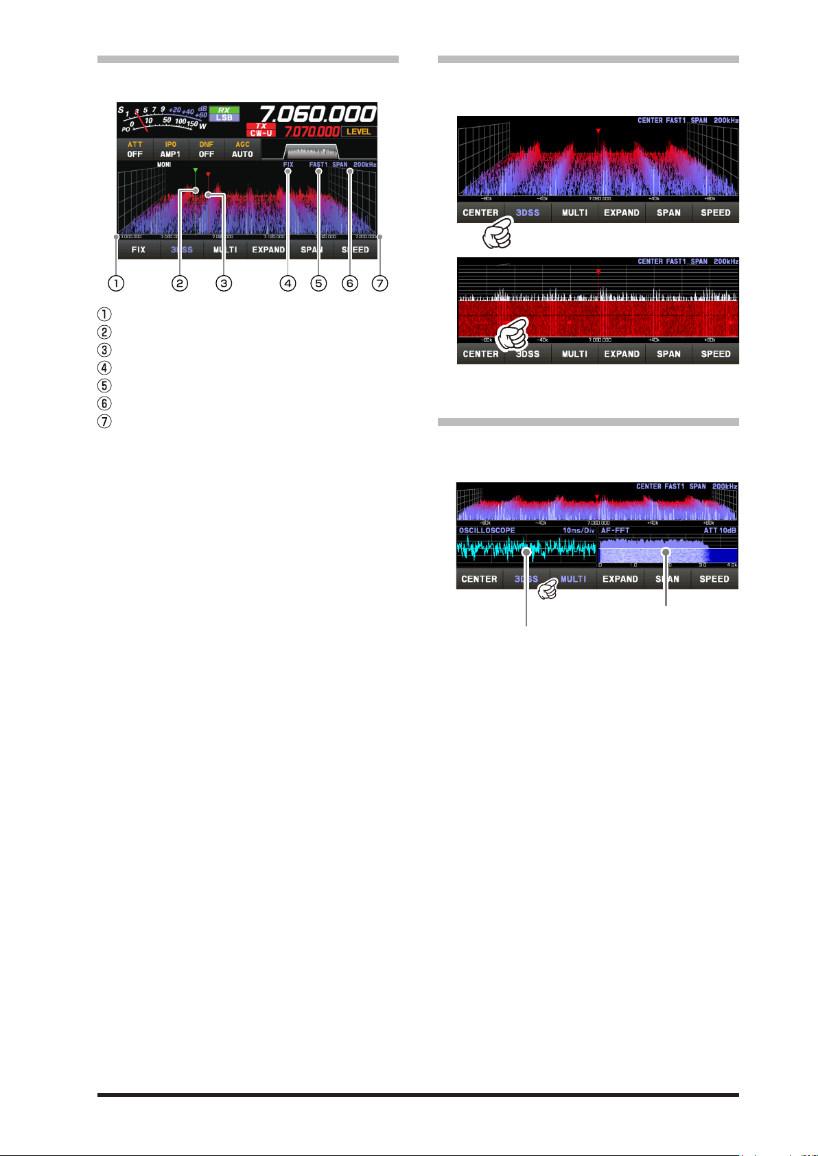
• FIX
Touch this area to set the attenuator.
Touch this area to set the level and sweep speed.
To use Fixed Mode, enter the start frequency of the
scope.
Display area start frequency
Marker* (Reception Frequency)
Marker* (Transmit Frequency)
Current display mode (FIX)
Sweep Speed
Scope Screen frequency span (display range).
The upper limit frequency of the display area.
*At factory shipment, marker display is ON.
FIX is displayed at the top of the scope screen.
Press and hold [FIX] while FIX is displayed, the frequency input screen will be displayed, and the start
frequency can be entered:
Example:
To enter 7.000.000 MHz
[0] → [7] → [ENT] or [7] → [.] → [ENT]
• 3DSS
Switch between the 3DSS display and the waterfall
display.
The display will change each time it is touched:
3DSS type
Waterfall type
• MULTI
In addition to the scope display, the oscilloscope
and AF-FFT are also presented.
Touch again to return to the original screen.
To enter 7.030.000 MHz
[7] → [.] → [0] → [3] → [ENT]
23
Page 26
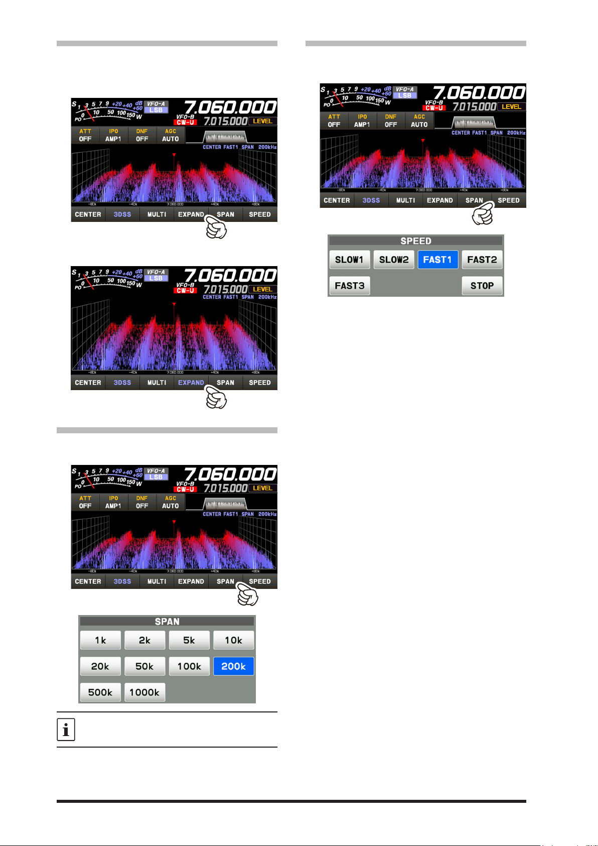
• EXPAND
The display area of the scope screen may be expanded vertically.
Touch to expand the display. Touch again to return
to the original.
Normal Display
• SPEED
Sets the Scope Display sweep speed. After touching, select the desired speed.
SLOW1 : sweep speed Slow
SLOW2 : sweep speed ↑
FAST1 : sweep speed Normal
FAST2 : sweep speed ↓
FAST3 : sweep speed Fast
STOP : Touch [STOP] to temporarily hold the
3DSS display and waterfall display operations. Touch [STOP] again or another
speed, to release the hold.
Larger View
• SPAN
Set the frequency span (display range) of the scope
screen. After touching, select the desired span.
The display level changes when SPAN is
changed, so reset the optimum display level
with [LEVEL] each time.
24
Page 27
Set with the FUNC knob
FUNC knob
Operate the [FUNC] knob to make the following settings related to the display.
LEVEL
PEAK
MARKER
COLOR
CONTRAST
DIMMER
The last function used is retained in the [FUNC] knob so it can be easily set by operating the [FUNC]
knob. Normally, it is suggested to utilize the [FUNC] knob as the [LEVEL] knob for the spectrum scope.
: Adjust the LEVEL of the scope for the best image on the screen.
: Adjust the color density with respect to the signal level on the scope screen in 5 steps (LV1
to LV5).
: ON/OFF Marker indicates the transmit and receive frequency position within the Scope
Display image.
: Changes the scope screen display color from 11 types.
: Adjust the TFT display contrast (dierence between light and dark) in 21 steps.
: Adjust the TFT display brightness in 21 steps.
• LEVEL
Adjust the level to make it easier to distinguish
between the desired signal and noise. The display
level changes depending on antenna gain, condition, frequency band, SPAN and so on.
Always adjust the LEVEL for the best image on the
screen.
Press the [FUNC] knob then touch [LEVEL], and
then turn the [FUNC] knob to select the desired level.
• On the 3DSS screen, weak signals may
be more easily observed by adjusting the
LEVEL so that the noise level can be seen
only a little, so always adjust the LEVEL
and use it at the optimum position.
• Be sure to make adjustments when
changing bands or changing SPAN.
• If the level is changed, the signal strength
also appears to change, but it does not
aect the actual signal input level.
• PEAK
The color density may be adjusted to the level of
the signal. Touch PEAK and then select the desired
color concentration.
Press the [FUNC] knob then touch [PEAK], and
then turn the [FUNC] knob to select the desired level.
LV1 : Thin
LV2 : ↑
LV3 : Normal
LV4 : ↓
LV5 : Dark
25
Page 28
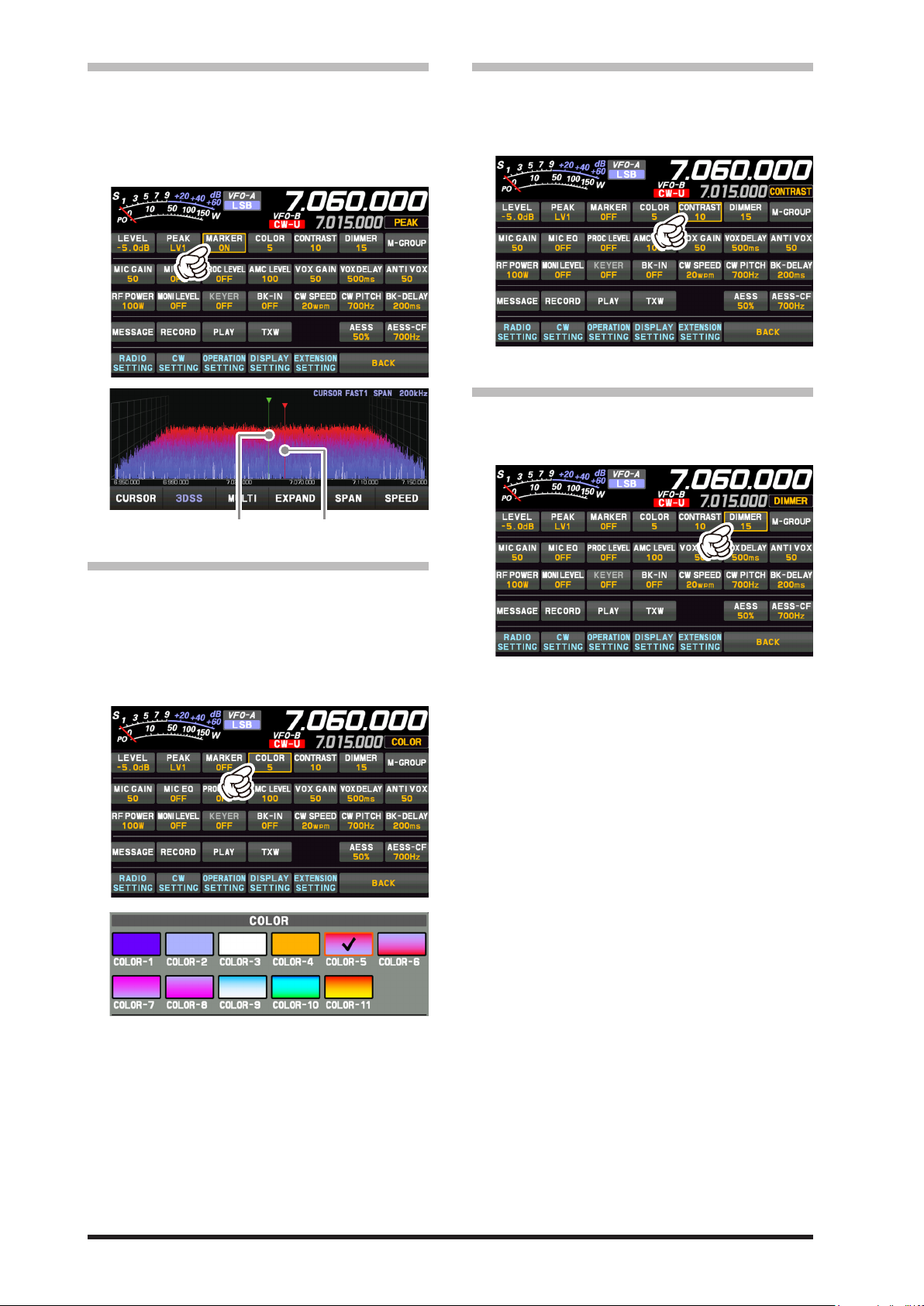
• MARKER
Receive Frequency Transmit Frequency
Displays markers that indicates the position of the
current receive and the transmit frequencies in the
spectrum.
Press the [FUNC] knob then touch [MARKER] to
turn the MARKER ON or OFF. Normally leave it
ON.
• Adjust contrast
Adjust the contrast of the TFT display.
Press the [FUNC] knob then touch [CONTRAST],
and then turn the [FUNC] knob to adjust the contrast.
• Adjusting the brightness (DIMMER)
Adjust the brightness of the TFT display.
Press the [FUNC] knob then touch [DIMMER], and
then turn the [FUNC] knob to adjust the brightness.
• COLOR
The display color of the scope screen can be
changed.
Press the [FUNC] knob then touch [COLOR], then
touch the desired color from the color selection
screen.
The Display Color selection screen will disappear
automatically after about 5 seconds.
26
Page 29
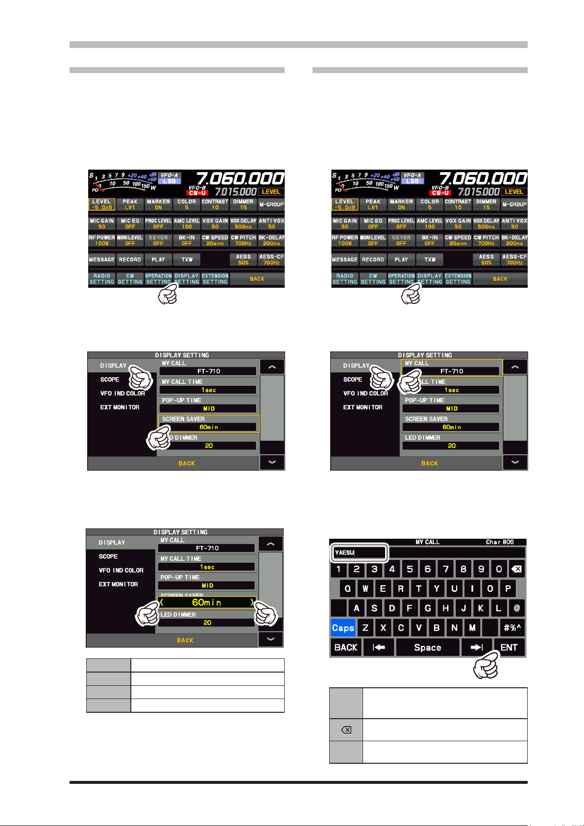
Other display settings
• Screen Saver
A Screen saver, to prevent burning of the TFT
screen will operate after a set time, if no transceiver function is operated.
1. Press the [FUNC] knob.
2. Touch [DISPLAY SETTING] or rotate the
[FUNC] knob to select [DISPLAY SETTING]
and then press the [FUNC] knob.
3. T o u c h [DISPLAY] → [SCREEN SAVER]
or rotate the [FUNC] knob to select an item
and press the [FUNC] knob.
• Inputting the Call Sign
Registered call signs names, and characters can
be displayed on the opening screen when the
power is turned ON.
1. Press the [FUNC] knob.
2. Touch [DISPLAY SETTING] or rotate the
[FUNC] knob to select [DISPLAY SETTING]
and then press the [FUNC] knob.
3. Touch [DISPLAY] →
[FUNC] knob to select the item and press the
[FUNC] knob.
[MY CALL] or rotate the
4. Rotate the [FUNC] knob, or touch “<” or “>”
on either side of the value to select the time
until the screen saver is employed (default
setting is 60 min).
OFF Screen saver is not employed.
15min Screen saver activates after 15 minutes.
30min Screen saver activates after 30 minutes.
60min Screen saver activates after 60 minutes.
5. Press the [FUNC] knob to save the new setting.
6. Touch [BACK] several times to return to normal operation.
4. Touch a character key. The touched character
will be displayed at the top of the screen. Enter each character of your call sign.
Up to 12 characters (letters, numbers, and
symbols) can be entered.
Caps
BACK
The input switches between lower and upper-case letters each time this symbol is
touched.
One character to the left of the cursor is
erased when this symbol is touched.
The display returns to the previous screen
when this symbol is touched.
27
Page 30

The cursor in the input field moves left or
/
right when these symbols are touched.
Space Insert space
ENT
The entered characters are confirmed and
the display returns to the previous screen
when this symbol is touched.
5. Touch [ENT] to save the new setting and exit to normal operation.
About TFT Displays
FT-710 utilizes a TFT liquid-crystal display.
Although TFT liquid-crystal displays are made using very precise technology, they are prone to develop dead pixels (dark dot) or pixels that are always on (bright dot). Please understand that such
phenomena do not constitute product defects or malfunctions. Rather, this phenomenon occurs due
to limitations in the manufacturing technology with respect to TFT liquid-crystal displays.
• Depending on the viewing angle, unevenness in color or brightness may occur. Please note that
any unevenness observed is inherent to the construction of TFT liquid crystal displays and therefore does not constitute a product defect or malfunction.
• If your TFT liquid-crystal display becomes dirty, please use a dry soft cloth or tissue to wipe the
display clean. If it is extremely dirty, moisten it with water or lukewarm water and wipe it o with a
soft cloth that has been wrung out tightly. Use of glass cleaner, household cleaners, organic solvents, alcohol, abrasives, and/or like substance may damage the TFT liquid-crystal display.
28
Page 31

Memo
29
Page 32

Front Panel Controls & Switches
ON/OFF (LOCK) Switch
Press and hold this switch for one second to turn
the transceiver ON or OFF.
Press this key to lock the following actions and
prevent accidental frequency or memory channel
changes:
• Frequency change with MAIN Dial knob;
• Frequency change and memory channel change
with the [STEP • MCH /
(“LOCK” appears in the frequency display.)
Press again to unlock.
SD memory card slot
A commercially available SD memory card may be
used to save transceiver settings, to save the memory contents, to screen capture and to update the
rmware.
• The SD card is not provided with the product.
• Not all SD cards sold commercially are
guaranteed to work with this transceiver.
TUNE
This is the ON/OFF switch for the FT-710 Automatic
Antenna Tuner.
Press the [TUNE] key briey to activate the antenna
tuner. Press the [TUNE] key briey again to disable
the antenna tuner.
Press the [TUNE] key for about 1 second to start
“automatic tuning”.
Since the transceiver transmits automatically during automatic tuning, make sure to
connect an antenna or dummy load before
tuning up.
When the antenna or dummy load does not
match the impedance, “HI-SWR” will appear
on the touch panel.
] knob.
VOX/MOX
VOX
This key enables automatic voice-actuated transmitter switching. While VOX is activated, the LED
inside this key glows orange.
1. Press the [VOX] key.
VOX feature is activated
2. Without pressing the PTT switch, speak into the
microphone in a normal voice level. When you
start speaking, the transmitter should be activated automatically.
When you finish speaking, the transceiver
should return to the receive mode (after a short
delay).
To cancel VOX and return to PTT operation, press
the [VOX] key once more.
• Adjusts the VOX GAIN
The VOX Gain may be adjusted to prevent unintended transmitter activation in a noisy environment. To adjust the VOX Gain:
1. Press the [FUNC] knob.
2. Touch [VOX GAIN] .
3. While speaking into the microphone, rotate the
[FUNC] knob to the point where the transmitter
is quickly activated by your voice, without background noise causing the transmitter to activate.
• Adjusts the VOX Delay Time
The “Hang-Time” of the VOX system (the transmit-receive delay after the cessation of speech)
may also be adjusted.
To set a dierent delay time:
1. Press the [FUNC] knob.
2. Touch [VOX DELAY] .
3. Rotate the [FUNC] knob while saying a brief syllable like “Ah” and listening to the hang time for
the desired delay.
30
Page 33

• Adjusts the VOX anti-trip sensitivity
GND
DOWN
The Anti-Trip setting sets the negative feedback
of receiver audio to the microphone, to prevent receiver audio from activating the transmitter (via the
microphone).
1. Press the [FUNC] knob.
2. Touch [ANTI VOX] .
3. Rotate the [FUNC] knob to prevent receiver audio from activating the transmitter (via the microphone).
MOX
Press and hold this key engages the PTT (Push to
Talk) circuit to activate the transmitter.
PHONES Jack
Connect headphones to this standard ϕ3.5 stereo
jack.
Inserting a headphone plug into this jack will deactivate the internal and external speakers.
When wearing headphones, we recommend
that you turn the AF Gain levels down to
their lowest settings before turning power
ON, to minimize the impact on your hearing
caused by audio “pops” during switch-on.
AUDIO (VFO-A/B)
AUDIO (VFO-A/B)
MIC
This 8-pin jack accepts input from a microphone utilizing the traditional YAESU HF transceiver pinout.
MAIN dial
The MAIN dial sets the operating frequency.
Rotate the MAIN dial knob to tune within the band,
and begin normal operation.
● The amount of frequency change depends on the
operation mode (default setting: see table below).
Operating Mode 1 Step 1 Dial Rotation
LSB / USB
CW-L / CW-U
DATA-L / DATA-U
RTTY-L / RTTY-U
PSK
AM / AM-N
FM / FM-N
DATA-FM / D-FM-N
“[FINE]” & “[FAST]” settings are ON. (These settings may
be changed in the Setting Menu.)
20Hz
[1Hz]
(100Hz)
10Hz
[1Hz]
(100Hz)
100Hz
[10Hz]
(1kHz)
4kHz
[200Hz]
(40kHz)
2kHz
[200Hz]
(20kHz)
20kHz
[2kHz]
(200kHz)
SSB/CW mode
“SSB/CW DIAL STEP”
RTTY/DATA mode
“RTTY/PSK DIAL STEP”
Adjusting the Main tuning DIAL torque
The torque (drag) of the Main DIAL knob may be
adjusted for operating preferences. Slide the lever
on the bottom side of the transceiver clockwise to
reduce the drag, or counter-clockwise to increase
the drag.
WIRE STAND
UP
+5V
MIC GND
MIC
PTT
GND
FAST
The heavy wire stand on the bottom of the
transceiver allows the transceiver to be tilted
upward for better viewing. Simply fold the
stand forward to raise the front of the transceiver, and fold it back against the bottom
case to lower the front of the FT-710.
31
Page 34

STEP•MCH /
●
STEP
Turning the [STEP•MCH/
the frequency in 5kHz steps (factory default settings).The frequency step of the step dial function
can be changed by the following operation.
1. Press the [FUNC] knob.
2. Select [OPERATION SETTING] → [TUNING] →
[CH STEP].
3. Rotate the [FUNC] knob, or touch “<” or “>” on either side of the value to select a frequency step.
Select from 1kHz/2.5kHz/5kHz/10kHz.
4. Press the [FUNC] knob, or wait for about 3 seconds to save the setting.
5. Touch [BACK] several times to return to normal
operation.
●
MCH
Turning the [STEP•MCH /
mode, and it will switch the memory channels.
] knob changes
] knob in memory
DSP interference removal functions
Pressing this knob momentarily, exchanges the SHIFT,
WIDTH, NOTCH, CONTOUR and APF.
These functions can be operated individually for VFO-A
and VFO-B, on each operating band.
1. SHIFT
IF SHIFT permits moving the Digital filter passband
higher or lower, without changing the pitch of the incoming signal, and thus reduce or eliminate interference. Because the tuned carrier frequency is not varied, there is no need to re-tune the operating frequency
to eliminate the interference.
The total passband tuning range for the IF SHIFT system is ±1.2kHz.
2. WIDTH
The IF WIDTH tuning system allows you to vary the
width of the DSP IF passband, to reduce or eliminate
interference.
Moreover, the bandwidth may actually be expanded
from its default setting, should you wish to enhance in-
coming signal delity when interference on the band is
low.
3. NOTCH
The IF NOTCH lter is a highly eective system that allows removing an interfering beat note or other carrier
signal from within the receiver passband.
4. CONTOUR
The Contour filter system provides a gentle pertur-
bation of the IF lter passband. The Contour is set to
either suppress, or boost specific frequency components, and thus enhances the sound and readability of
a received signal
5. APF
During CW operation, when interference or noise is
present, the center frequency is automatically set to the
PITCH frequency, making it easier to hear the desired
signal
●
Setting method
1. Press the [STEP • MCH /
spectrum area.
The LED of the [STEP • MCH /
orange.
] knob or touch the
] knob lights
32
2. Rotate the [STEP • MCH / ] knob to select the
function, then press the [STEP • MCH /
(The function may also be selected by touching the
function name.)
3. While the set value blinks, rotate the [STEP • MCH /
4. Press the [STEP • MCH /
] knob to set the desired value.
] key and then press
the [DSP RESET] key to conrm the setting.
] knob.
Page 35

1. SHIFT
A B
IF BANDWIDTH IF BANDWIDTH
QRM
STEP
MCH/ knob
BA
Desired Signal
STEP
MCH/ knob
The figure below is a conceptual diagram of
WIDTH.
1. Press the [STEP • MCH /
2. Rotate the [STEP • MCH /
] knob.
] knob to select
“SHIFT”, then press the [STEP • MCH /
(The function may also be selected by touching
“SHIFT”.)
The shift frequency blinks.
3. Rotate the [STEP • MCH /
] knob to the left or
right to reduce interfering signals.
4. Press the [STEP • MCH /
] knob, then press
the [DSP RESET] key or wait for about 5 seconds to
save the setting.
Press and hold the [STEP • MCH /
] knob to
quickly move the lter passband to center.
Refer to Figure “A” and notice the depiction of the
IF DSP filter as a thick line in the center of the
passband. In Figure “B", you can see the eect of
rotating the [STEP • MCH /
] knob.
The interference level is reduced by moving the lter passband so that the interference is outside of
the passband.
Desired Signal
Desired Signal
QRM
] knob.
IF BANDWIDTH
•
3. NOTCH
1. Press the [STEP • MCH / ] knob.
2. Rotate the [STEP • MCH /
“NOTCH”, then press the [STEP •MCH/
knob.
(The function may also be selected by touching
“NOTCH”.)
The NOTCH center frequency blinks.
3. Rotate the [STEP • MCH /
“null” position of the Notch lter.
4. Press the [STEP • MCH /
the [DSP RESET] key or wait for about 5 seconds to
save the setting.
Press and hold the [STEP • MCH /
return the center frequency to its initial value.
] knob to select
] knob to adjust the
] knob, then press
] knob to
]
2. WIDTH
1. Press the [STEP • MCH / ] knob.
2. Rotate the [STEP • MCH /
“WIDTH”, then press the [STEP •MCH/
knob. (The function may also be selected by touching “WIDTH”.)
The lter bandwidth blinks.
3. Rotate the [STEP •MCH /
er-clockwise to narrow the bandwidth and reduce
interference.
4. Press the [STEP • MCH /
the [DSP RESET] key or wait for about 5 seconds to
save the setting.
Press and hold the [STEP • MCH /
reset the digital lter bandwidth to its initial value.
The default bandwidths, and total bandwidth adjustment range, will vary according to the operating mode
(see table below).
Operating Mode IF BANDWIDTH
LSB / USB 300Hz - 4000Hz (default: 3000Hz)
CW-L / CW-U
RTTY-L / RTTY-U
DATA-L / DATA-U
PSK
AM / FM-N / D-FM-N 9000Hz
AM-N 6000Hz
FM / DATA-FM 16000Hz
50Hz - 4000Hz (default: 500Hz)
50Hz - 4000Hz (default: 600Hz)
] knob to select
] knob count-
] knob, then press
] knob to
The bandwidth of the NOTCH filter (either
narrow or wide) may be adjusted using Menu
item “IF NOTCH WIDTH” (page 92).
The factory default setting is “WIDE”.
The performance of the IF Notch filter is shown
in Figure “A", where the effect of rotation of the
[STEP • MCH /
] knob is depicted. In Figure
“B” you can see the notching eect of the IF Notch
]
lter as you rotate the [STEP • MCH /
to eliminate the incoming interference.
Notch QRM (Heterodyne)
IF BANDWIDTH IF BANDWIDTH
•
] knob
33
Page 36

4. CONTOUR
STEP•MCH/ knob
5. APF
The APF function can be operated individually for
VFO-A and VFO-B, on each operating band (The settings are common to VFO-A and VFO-B, and each operating band).
1. Press the [STEP • MCH / ] knob.
2. Rotate the [STEP •MCH/
“CONTOUR”, then press the [STEP •MCH /
knob.
(The function may also be selected by touching
“CONTOUR”d.)
The center frequency of “CONTOUR” blinks.
If “CONTOUR” is not displayed, select “APF”
and press the [STEP • MCH /
display “CONTOUR”.
3. Rotate the [STEP • MCH /
the most natural-sounding audio reproduction of the
incoming signal.
4. Press the [STEP • MCH /
the [DSP RESET] key or wait for about 5 seconds to
save the setting.
Press and hold the [STEP • MCH /
return the center frequency to its initial value.
The gure below is a conceptual diagram of CONTOUR.
IF BANDWIDTH IF BANDWIDTHIF BANDWIDTH
] knob to select
] knob to
] knob to achieve
] knob, then press
] knob to
]
1. Press the [STEP • MCH / ] knob.
2. Rotate the [STEP •MCH/
“APF”, then press the [STEP • MCH /
(The function may also be selected by touching
“APF”.)
The center frequency of APF blinks.
If “APF” is not displayed and Contour is
•
displayed, and it is OFF. S
and press the [STEP •MCH/ ] knob
3 times to active “APF”.
If “APF” is not displayed and Contour is
•
displayed, and it is ON. Select Contour
and press the [STEP •MCH/ ] knob
3 times to active “APF”.
3. Rotate the [STEP • MCH /
right to reduce any interference.
4. Press the [STEP • MCH /
the [DSP RESET] key or wait for about 5 seconds to
save the setting.
5. Press and hold the [STEP • MCH /
restore the APF peak center frequency setting to
“0Hz”, and disable the APF function.
The APF bandwidth can be selected from
NARROW / MEDIUM / WIDE via the Menu
item “APF WIDTH” (page 92).
] knob to select
] knob.
elect Contour
] knob to the left or
] knob, then press
] knob to
• Adjusting the GAIN of the CONTOUR Circuit
1. Press the [FUNC] knob.
2. Select [OPERATION SETTING] → [RX DSP] →
[CONTOUR LEVEL].
3. Rotate the [FUNC] knob, or touch “<” or “>” on
either side of the value to set the CONTOUR cir-
cuit gain.
4. Press the [FUNC] knob, or wait for about 3 seconds to save the setting.
5. Touch [BACK] several times to return to normal
operation.
• Sets the Bandwidth (“Q”) of the CONTOUR Circuit
1. Press the [FUNC] knob.
2. Select [OPERATION SETTING] → [RX DSP] →
[CONTOUR WIDTH].
3. Rotate the [FUNC] knob, or touch “<” or “>” on
either side of the value to set bandwidth (“Q”) of
the CONTOUR circuit.
4. Press the [FUNC] knob, or wait for about 3 seconds to save the setting.
5. Touch [BACK] several times to return to normal
operation.
DSP RESET
Press and hold the [DSP RESET] key to reset
to the default values of the “SHIFT”, “WIDTH”,
“NOTCH”, “CONTOUR”, and “APF” settings for the
current band. A short press while setting “SHIFT”,
“WIDTH”, “NOTCH”, “CONTOUR” or “APF” conrms the setting and returns to the normal screen.
34
Page 37

Press and hold the [DNR] key
DNR (Digital Noise Reduction)
The Digital Noise Reduction (DNR) system is designed to reduce the level of ambient noise found
on the HF and 50 MHz bands. The (DNR) system
is especially effective during SSB operation. Any
of 15 different noise-reduction algorithms can be
selected; each of these algorithms was created to
deal with a dierent noise prole. You will want to
experiment with the DNR system to find the best
setting corresponding to the noise currently being
experienced.
The DNR function can be operated individually for
VFO-A band and VFO-B.
Press the [DNR] key to enable the DNR operation.
To disable DNR operation, press the [DNR] key
once more.
• Adjusting the DNR Level
DNR Level
to display the DNR level.
BAND (
Touch the display to select
Press the [BAND] key, the operation band selection
screen appears on the display, so touch the desired
band. When you touch it, the band will be conrmed
for about 1 second and then return to the operating
screen.
Rotate the [FUNC] knob to select
Press the [BAND] key, the operation band selection
screen appears on the display. Rotate the [FUNC]
knob to select the desired band.
QMB (Quick Memory Bank)
The current operation status can be stored in a
dedicated memory channel (QMB: Quick Memory
Bank) with one touch.
Operating Band Selection
• QMB Channel Storage
The initial number is 5 QMB memories, but
this can be increased to 10 channels.
1. Tune to the desired frequency on the VFO mode.
2. Press and hold the [QMB] key. The “beep” will
conrm that the VFO contents have been written
to the currently available QMB memory.
)
Turn the [FUNC] knob to
After adjusting to a DNR level, the DNR level display
disappears after about 3 seconds.
After adjusting the DNR level, the operation of the
[FUNC] knob returns to the operation that was used
before adjusting the DNR level.
A/B
Pressing this key momentarily, exchanges the
VFO-A and VFO-B frequency data. Press and hold
this key, and the frequency displayed in gray in the
lower row becomes the same as the frequency displayed in white in the upper row. The operation will
be the same mode as the upper row.
adjust the DNR level.
• Repeated pressing and holding of the
[QMB] key will write the VFO contents to
successive QMB memories.
• Once all five (or ten) QMB memories
have data on them, previous data will be
over-written on a rst-in, rst-out basis.
• QMB Channel Recall
1. Press the [QMB] key.
The current QMB channel data will be shown on
the frequency display area.
The “VFO” or “Memory Channel number” will be
replaced by “QMB”.
2. Repeatedly pressing the [QMB] key will step
through the QMB channels:
3. Press the [V/M
mode.
] key to return to the VFO
• Changing the number of
QMB channels
The QMB channels can be selected from “5 channels” or “10 channels”.
1. Press the [FUNC] knob.
2. Select [
→ [QMB CH].
3. Select “5ch” or “10ch”.
4. Press the [FUNC] knob, or wait for about 3 seconds to save the setting.
5. Touch [BACK] several times to return to normal
operation.
OPERATION SETTING
] → [
GENERAL
]
35
Page 38

VMI (VFO mode indicator)
Shows the current operating status of the VFO at
a glance. The indicator lights up in the following
colors according to the operating status (factory default settings).
Blue: VFO-A
Green: VFO-B
White: Memory mode
Red: Clarier or Split Operation
The lighting colors can be changed by the following
operations:
1. Press the [FUNC] knob.
2. Select [DISPLAY SETTING] → [VFO IND COLOR].
3. Select the item whose color you want to change.
4. Rotate the [FUNC] knob, or touch “<” or “>” on
either side of the value to select the Color.
Select the color of the “3” mark in the table below for each item.
Blue Green Red White None
VFO-A
VFO-B
Memory
mode
Clarier /
Split
5. Press the [FUNC] knob, or wait for about 3 seconds to save the setting.
6. Touch [BACK] several times to return to normal
operation.
3 3 3
3 3 3
3 3
- -
-
3
-
3
-
3 3
-
3
3
BUSY/TX indicator
This indicator glows green* when the squelch
opens, and glows red during transmit.
* Glows green only when the [RF GAIN/SQL] knob
is set to “SQL” or “SQL(FM only)”.
NAR (Narrow)
This key is used to set the DSP (digital) IF lters to
Narrow bandwidth. Press this key again to return
the bandwidth control to the WIDTH system.
• Change the bandwidth by
pressing the NAR key
1. Press the [FUNC] knob.
2. The setting menu items to be set dier depending on the operating mode, so call the setting
items referring to the following:
LSB / USB mode
[RADIO SETTING] → [MODE SSB] →
CW-L / CW-U mode
[CW SETTING] → [MODE CW] → [NAR WIDTH]
DATA-L / DATA-U / PSK mode
[RADIO SETTING] → [MODE PSK/DATA] →
RTTY-L / RTTY-U mode
[RADIO SETTING] → [MODE RTTY] →
3. Rotate the [FUNC] knob, or touch “<” or “>” on
either side of the value to set the bandwidth.
4. Press the [FUNC] knob, or wait for about 3 seconds to save the setting.
5. Touch [BACK] several times to return to normal
operation.
FINE/FAST
FINE Tuning (Tuning of 1Hz)
In the LSB, USB, CW-L, CW-U, DATA-L, DATA-U,
RTTY-L, RTTY-U or PSK mode, the frequency
can be adjusted in 1 Hz steps.
● The AM, AM-N, FM, FM-N, DATA-FM and
1. Press the [FINE/FAST] key.
2. Rotate the MAIN dial knob.
3. Press the [FINE/FAST] key again to return to
FAST Tuning (Tuning of 10 times)
The frequency can be adjusted in 10 times steps.
1. Press and hold the [FINE/FAST] key.
2. Rotate the MAIN dial knob.
3. Press the [FINE/FAST] key again to return to
→ [NAR WIDTH]
→ [NAR WIDTH]
→ [NAR WIDTH]
Mode Available Settings (Default: Bold)
LSB / USB 300 - 1500 - 4000
CW-L / CW-U 50 - 250 - 4000
DATA-L / DATA-U
RTTY-L / RTTY-U
PSK
D-FM-N modes may be adjusted in 10 Hz
steps.
The “FINE” indicator lights in the display.
the original frequency step.
The “FAST” indicator lights in the display.
the original frequency step.
50 - 300 - 4000
36
Page 39

RF GAIN/SQL
RF (default setting)
The RF Gain control provides manual adjustment
of the gain levels for the receiver RF and IF stages, to account for noise and signal strength conditions at the moment.
[RF GAIN/SQL] knob is normally in the fully
clockwise position.
• Before operation, set the operation of
the [RF GAIN/SQL] control to “RF” (see
below). The default setting is “RF”.
• It does not operate in FM/FM-N/
DATA-FM and D-FM-N mode.
SQL
The squelch system allows the back-ground
noise to be muted when no signal is being received.
Normally, the squelch is not used during SSB or
CW operation.
Before operation, set the operation of the
[RF GAIN/SQL] control to “SQL”. The default setting is “RF”.
Rotate the [RF GAIN/SQL] knob to adjust the
squelch until the noise disappears.
If the squelch knob is turned too far to the
right, weak signals cannot be heard
• Switching the operation of the
[RF GAIN/SQL] knob
1. Press the [FUNC] knob.
2. Select [OPERATION SETTING]→[GENERAL]
→ [RF/SQL VR].
3. Select “RF” or “SQL”.
4. Press the [FUNC] knob, or wait for about 3 seconds to save the setting.
5. Touch [BACK] several times to return to normal
operation.
MODE (
Touch the display to select
Press the [MODE] key or touch the operation mode
area, the operation mode selection screen appears
on the display, so touch the desired mode.
Rotate the [FUNC] knob to select
Press the [MODE] key or touch the operation mode
area, the operation mode selection screen appears
on the display. Rotate the [FUNC] knob to select
the desired mode.
Operating Mode Selection
)
RF GAIN/SQL settings cannot be set separately for the VFO-A and the VFO-B.
AF GAIN
Sets the audio level.
• Touch [PRESET] to display the settings
that apply to the FT8 operation.
• When changing modes from SSB to CW,
the frequency will shift on the display,
even though the actual tone that is heard
does not change.
This shift represents the BFO offset between the “zero beat” frequency and the
audible CW pitch (tone). The pitch is programmed via Menu item “CW FREQ DISPLAY”.
37
Page 40

When the receive frequency is offset by +20Hz.
ZIN/SPOT
ZIN
Press the [ZIN/SPOT] switch momentarily to adjust
the receiving frequency and zero-in automatically
while receiving a CW signal.
SPOT
While pressing and holding [ZIN/SPOT], the tone is
output from the speaker. This tone corresponds to
the pitch of your transmitted signal. If you adjust the
receiver frequency until the pitch of the received
CW signal matches that of the Spot tone, the transmitted signal will be precisely matched to that of the
other station.
The Spot tone audio level may be adjusted by
pressing the [FUNC] knob, then touching [MONI
LEVEL], and rotating the [FUNC] knob.
SPLIT
A powerful capability of the FT-710 is its exibility
in Split Frequency operation using the VFO-A and
VFO-B frequency registers. This makes the FT710 especially useful for high-level DX-peditions.
The Split operation capability is very advanced and
easy to use.
1. Press the [A/B] key, then set the upper VFO frequency to the desired receive frequency.
2. Press the [SPLIT] key, and then set the lower
VFO frequency to the desired transmit frequency.
During Split operation, the upper VFO register will
be used for reception, while the lower VFO register
will be used for transmission. Press the [SPLIT] key
again to cancel Split operation.
● Rotate the main dial while holding down the
[STEP • MCH /
will change the transmit and receive frequencies
in the same step at the same time.
● The receive and transmit frequencies can be set
to dierent bands or operation modes.
● During split operation, touch [TXW] after pressing
the [FUNC] knob, to receive the transmit frequency while pressing the [FUNC] knob.
● Press and hold the [SPLIT] key to change the re-
ceive frequency.
] knob during split operation
CLAR (Clarier)
The clarifier is used to adjust the transceiver receive frequency to match the other station transmit
frequency and improve the audio; or to shift the
transmit frequency of this station when the transmit
frequency of the contact station is shifted.
The display will indicate “CLAR RX” → “CLAR TX”
→ “CLAR RXTX” in red, each time the [CLAR] key
is pressed, and the clarier will activate.
Turning the MAIN dial changes the clarifier offset
frequency.
To turn the clarifier OFF, repeatedly press the
[CLAR] key until the Clarier status is not displayed.
To clear out the programmed clarifier offset altogether, and reset it to “zero,” press and hold the
[CLAR] key.
•
RX Clarier
If the transmit frequency of the contact station
deviates, this receiver clarifier frequency can
be changed leaving this transmit frequency unchanged.
1. Press the [CLAR] key.
2. Rotate the MAIN dial knob to change only the
receive frequency.
Osets of up to ±9995Hz may be set using
the Clarier.
3. To cancel Clarifier operation, press the [CLAR]
key three times.
● Since the oset amount is memorized, when the
clarier function is operated again, the same o-
set amount is set.
• Adjust transmit frequency to the
oset frequency
After changing the receiver frequency with RX
Clarier, the transmitter frequency can be set to the
same frequency as the receiver.
1. After osetting the receiver frequency, press the
[CLAR] key twice.
The transmit frequency becomes the same as
the receive frequency.
“CLAR RX” of the display changes to “CLAR
RXTX”.
2. Press the [CLAR] key twice, only the receive fre-
quency returns to the oset state.
“CLAR RXTX” of the display changes to “CLAR
RX”.
38
Page 41

• TX Clarier
after about 3 seconds.
Press and hold the [NB] key to
The transmit frequency can be changed without
moving the receive frequency of the transceiver.
Normally, the clarier is used to move only the receive frequency and compensate for the deviation
of the transmission frequency of the contact station,
however alternatively, only the transmit frequency
can be moved without changing the transmitter.
When responding to an operator that is called by a
large number of stations such as in a contest, etc.,
the response rate may increase if the transmit frequency is moved slightly.
1. Press the [CLAR] key twice.
2. Rotate the MAIN dial knob to change only the
transmit frequency.
• The “CLAR TX” will appear in the display,
and the programmed oset will be applied
to the transmit frequency.
• Osets of up to ±9995Hz may be set us-
ing the Clarier.
NB
The FT-710 includes an eective IF Noise Blanker,
which can signicantly reduce noise caused by au-
tomotive ignition systems.
The NB function can be operated individually for
VFO-A band and VFO-B, on each operating band.
Press the [NB] key to enable the Noise Blanker operation. To disable Noise Blanker operation, press
the [NB] key once more.
• Adjusting the Noise Blanker Level
NB Level
display the NB level.
3. To cancel Clarifier operation, press the [CLAR]
key twice.
To clear out the programmed clarifier offset altogether, and reset it to “zero”, press and hold the
[CLAR] key.
• To oset the frequency with the
TX Clarier Adjust receive frequency
When the transmit frequency is oset with the TX
Clarier, it can be reset to the same frequency as
the TX frequency oset from the receive frequency.
1. After osetting the transmit frequency, press the
[CLAR] key.
The receive frequency becomes the same as the
transmit frequency.
“CLAR TX” of the display changes to “CLAR
RXTX”.
2. Press the [CLAR] key three times, only the trans-
mit frequency returns to the oset state.
“CLAR RXTX” of the display changes to “CLAR
TX”.
Turn the [FUNC] knob to adjust the NB level.
After adjusting to a NB level, the NB level display disappears
The NB function may be less eective on some
other types of interference.
• Adjusting the Noise Attenuation
1. Press the [FUNC] knob.
2. Select [OPERATION SETTING]→[RX DSP]
→[NB REJECTION].
3. Rotate the [FUNC] knob to set the noise attenuation (LOW / MID / HIGH).
4. Press the [FUNC] knob, or wait for about 3 seconds to save the setting.
5. Touch [BACK] several times to return to normal
operation.
• Reduces longer duration pulse noise
Reduces long duration noise as well as pulse noise.
1. Press the [FUNC] knob.
2. Select [OPERATION SETTING]→[RX DSP] →
[NB WIDTH] .
3. Rotate the [FUNC] knob to select the value that
will reduce the noise.
4. Press the [FUNC] knob, or wait for about 3 seconds to save the setting.
5. Touch [BACK] several times to return to normal
operation.
39
Page 42

Voice Communications (SSB and AM)
FUNC knob
When transmitting in SSB or AM mode
The FT-710 transmit audio circuit can be set to the optimum operating level by individually adjusting the
input and output gains of the microphone amplier.
The AMC (Automatic Microphone Gain Control) regulates the microphone audio so that distortion does not occur, even if excessive audio is input.
1. Adjust Microphone gain
Touch the Meter Display and then touch “ALC” to
select the ACL Meter.
1. Press the [FUNC] knob.
2. Touch [MIC GAIN].
3. Key TX and adjust the [FUNC] knob to set the
input level of the Microphone Amplier to the
position where the ALC Meter needle does
not exceed the ALC zone on the audio peaks.
2. Adjust the AMC gain
Touch the Meter Display and then touch “COMP”
to select the COMP Meter.
1. Press the [FUNC] knob.
2. Touch [AMC LEVEL].
3. Activate the transmit and speak into the microphone while adjusting the AMC level with
the [FUNC] knob.
● Adjust the AMC to a point where the COMP
Meter deection does not exceed “10dB” on the
audio peaks.
Setup is completed.
The AMC function only works in LSB, USB, AM,
AM-N, DATA-L, DATA-U and PSK modes.
It does not work in other modes.
Set with the FUNC knob
Operate the [FUNC] knob to make the following settings.
PROC LEVEL: Adjust the level of the speech processor function.
RF POWER: Adjust the transmit power.
MONI LEVEL: Adjust the monitor level.
The last function used is retained in the [FUNC] knob so it can be easily set by operating the [FUNC]
knob. Normally, it is suggested to utilize the [FUNC] knob as the [LEVEL] knob for the spectrum scope.
40
Page 43

Speech Processor
The FT-710 Speech Processor is designed to
increase “talk power” by increasing the average
power output of the transmitted SSB signal.
The speech processor function only works
in LSB/USB mode. It does not work in other
modes.
1. Adjust the MIC gain as described on the previous page.
2. Press the [FUNC] knob.
3. Touch [PROC LEVEL].
4. Touch the Meter area on the display to select
the “COMP” meter.
The transmit meter becomes the “COMP” meter.
5. Press the PTT switch on the microphone, and
speak into the microphone in a normal voice
level.
6. Adjust the [FUNC] knob to set the compression level within 10 dB.
The Transmit Monitor is a helpful aid to verify
●
proper adjustment of the Compression level.
● The “PROC” indicator lights in the display.
Rotate the [FUNC] knob to the left to turn the
speech processor function “OFF”.
The speech processor can distort the transmit
waveform when used to increase the average TX
power, so it is not used in normal communication.
● Setting of maximum transmission output
The maximum transmit power can be set for each
of the HF Bands, the 50MHz band and the AM
mode. Set it according to operating conditions,
when high transmit power is not needed.
1. Press the [FUNC] knob.
2. Select [OPERATION SETTING] → [TX GEN-
ERAL].
3. Rotate the [FUNC] knob to select the item
you want to set.
HF MAX POWER (HF band)
(The setting range is 5 to 100 W)
50M MAX POWER (50 MHz band)
(The setting range is 5 to 100 W)
70M MAX POWER (70 MHz band)
(The setting range is 5 to 50 W)
AM MAX POWER (AM mode)
(The setting range is 5 to 25 W)
4. Press the [FUNC] knob, or wait for about 3
seconds to save the setting.
5. Touch [BACK] several times to return to normal operation.
MONI (Monitor)
Use the Monitor feature to listen to the quality of
the transmitted signal.
1. Press the [FUNC] knob.
2. Touch [MONI LEVEL].
RF Power output control
Turn the [FUNC] knob to adjust the RF power
output.
1. Press the [FUNC] knob.
2. Touch [RF POWER].
3. Rotate the [FUNC] knob to adjust the RF
power.
When transmitting in the AM mode, set a maximum (carrier) power output of 25 Watts.
3. Rotate the [FUNC] knob to adjust the Monitor
level.
Transmit audio monitor is not activate in the FM,
FM-N, DATA-FM and D-FM-N modes.
● If you are using the speaker for monitoring,
instead of headphones, excessive advancement of the Monitor level can cause feedback
to occur. Additionally, this feedback can cause
the VOX system to hang up in a loop, making
it impossible to return to receive. Therefore,
we recommend the use of headphones, if at all
possible, or the minimum usable setting of the
Monitor level, if the speaker must be used.
4. To cancel the monitor function, turn the
[FUNC] knob to set “MONI LEVEL” to “OFF”.
● Because the Monitor feature samples the trans-
mitter IF signal, it can be very useful for checking the adjustment of the Speech Processor or
Parametric Equalizer on SSB, and for checking
the general signal quality on AM.
41
Page 44

Parametric Microphone Equalizer
The FT-710 includes a unique Three-Band Parametric Microphone Equalizer that provides precise, in- dependent control over the low, mid and treble ranges in the voice waveform. One group of settings may be
utilized when the Speech Processor is O, and an alternate group of settings when the Speech Processor
is On (SSB mode only). The speech processor feature is described in the next chapter.
Parametric microphone equalizer function is activated only in LSB, USB, AM, AM-N, FM and FM-N modes.
• Setup the
Parametric Microphone Equalizer
1. Set the RF output power to minimum value.
We recommend connecting a dummy load
to one of the Antenna jacks, and monitoring
the signal on a separate receiver, to prevent
interference to other users.
2. Press the [FUNC] knob.
3. Touch [MIC EQ].
Parametric Microphone Equalizer function is
activated.
● To adjust the Parametric Microphone Equalizer with the Speech Processor engaged,
activated the Speech Processor.
4. Press the [FUNC] knob.
5. Touch [MONI LEVEL].
6. Rotate the [FUNC] knob to adjust the Monitor
level.
7. Press the [FUNC] knob.
8. Select [
9. Rotate the [FUNC] knob to find Menu items
[PRMTRC EQ1 FREQ] through [PRMTRC
EQ3 BWTH]; these parameters apply to the
adjustment of the Parametric Microphone
Equalizer when the Speech Processor is disabled.
Menu items [P PRMTRC EQ1 FREQ]
through [P PRMTRC EQ3 BWTH] apply to
the adjustment of the Parametric Microphone
Equalizer when the Speech Processor is
engaged.
10. Rotate the [FUNC] knob, or touch “<” or “>”
on either side of the value to adjust a particular Menu item.
11. Press and hold the PTT switch, and speak
into the microphone while listening to the effect of the adjustments being made. Because
the overall sound will change with each adjustment, make several passes through each
adjustment area, to be sure that the optimum
OPERATION SETTING
]→[TX AUDIO].
settings are achieved.
●The best way to hear the eects of the adjustments is to wear headphones (connected to the monitor receiver) while listening to
the transmitted signal.
12. When all adjustments are satisfactory, press
the [FUNC] knob, or wait for about 3 seconds
to save the setting.
13. Touch [BACK] several times to return to normal operation.
• Activate the
Parametric Microphone Equalizer
1. Adjust the MIC gain, as described on page
40.
2. Press the [FUNC] knob.
3. Touch [MIC EQ].
Parametric Microphone Equalizer function is
activated.
4. Press the PTT switch on the microphone, and
speak into the microphone in a normal voice
level.
To cancel the Parametric Microphone Equalizer
function, repeat steps 2 and 3 above, and choose
“OFF” in step 3.
42
Page 45

Parametric Gain
3-Stage Parametric Equalizer Adjustments (Speech Processor: “OFF”)
PRMTRC EQ1 FREQ (Low) “100” (Hz) - “700” (Hz) / OFF
Center Frequency
PRMTRC EQ3 FREQ (High) “1500” (Hz) - “3200” (Hz) / OFF
PRMTRC EQ1 LEVEL (Low) “-20” (dB) - “+10” (dB)
Parametric Gain
PRMTRC EQ3 LEVEL (High) “-20” (dB) - “+10” (dB)
PRMTRC EQ1 BWTH (Low) “0” - “10”
Q (Bandwidth)
PRMTRC EQ3 BWTH (High) “0” - “10”
OFFPRMTRC EQ2 FREQ (Mid) “700” (Hz) - “1500” (Hz) / OFF
+5PRMTRC EQ2 LEVEL (Mid) “-20” (dB) - “+10” (dB)
10PRMTRC EQ2 BWTH (Mid) “0” - “10”
3-Stage Parametric Equalizer Adjustments (Speech Processor: “ON”)
P PRMTRC EQ1 FREQ (Low) “100” (Hz) - “700” (Hz) / OFF
Center Frequency
Parametric Gain
Q (Bandwidth)
P PRMTRC EQ3 FREQ (High) “1500” (Hz) - “3200” (Hz) / OFF
P PRMTRC EQ1 LEVEL (Low) “-20” (dB) - “+10” (dB)
P PRMTRC EQ3 LEVEL (High) “-20” (dB) - “+10” (dB)
P PRMTRC EQ1 BWTH (Low) “0” - “10” 2
P PRMTRC EQ2 BWTH (Mid) “0” - “10”
P PRMTRC EQ3 BWTH (High) “0” - “10”
OFFP PRMTRC EQ2 FREQ (Mid) “700” (Hz) - “1500” (Hz) / OFF
Center Frequency: The center frequency of each of the three bands may be adjusted.
Gain: The amount of enhancement (or suppression) within each band may be adjusted.
Q: The bandwidth over which the equalization is applied may be adjusted.
0P PRMTRC EQ2 LEVEL (Mid) “-20” (dB) - “+10” (dB)
1
43
Page 46

Voice Memory
The Voice Memory capability of the FT-710 may be used to store and replay often repeated messages.
The Voice Memory includes ve memories.
The Voice Memory may be operated from the Display Panel, or from the optional FH-2 Remote Control
Keypad, which plugs into the rear panel REM jack.
When performing Voice memory, a commercially available SD card is necessary.
• Recording Your Own Voice in Memory
1. Insert a commercially available SD memory
card into the SD card slot on the left side of
the transceiver.
2. Select the LSB, USB, AM, AM-N, FM or FM-N
mode.
When using FH-2, go to step 5.
3. Press the [FUNC] knob.
4. Touch [MESSAGE].
The “MESSAGE MEMORY” screen will be
displayed.
5. Touch [MEM] on the display or press the
[MEM] key on the FH-2.
A blinking “REC” will appear in the display.
If a [1] through [5] key (see next step) is not
pressed within 10 seconds, the memory
storage process will be cancelled.
6. Touch [1] through [5] on the display or press
any of the FH-2 keys numbered [1] through [5]
to select that memory storage register.
7. Press the microphone PTT switch momentarily. The “REC” icon will glow steadily and
recording will begin.
● “REC” lights up on the display while record-
ing is in progress.
● Remember that the time limit for recording
any message is 90 seconds.
8. Release the PTT switch or press the FH-2
[MEM] key to complete the message storage
process.
• Checking the Recording
1. Press the [FUNC] knob.
2. Touch [BK-IN] to turn OFF the BK-IN function.
When using FH-2, go to step 4.
3. Touch [MESSAGE].
The “MESSAGE MEMORY” screen will be
displayed.
4. Touch [1] through [5] on the display or press
the FH-2 [1] through [5] key (whichever register was just recorded in). The “MSG” icon will
appear in the display and the audio recorded
in the Voice Memory will be heard.
● To adjust the playback volume level, turn
the [FUNC] knob or touch [RX LEVEL]
when not playing, and then turn the [FUNC]
knob to adjust.
• Transmitting the Recorded Message
1. Select the LSB, USB, AM, AM-N, FM or FM-N
mode.
2. Press the [FUNC] knob.
3. Touch [BK-IN] to turn ON the BK-IN function.
When using FH-2, go to step 5.
4. Touch [MESSAGE] .
5. Touch [1] through [5] on the display or press
the FH-2 [1] through [5] key (whichever
memory was recorded in). A “MSG” icon will
appear in the display and the message will be
transmitted.
● To adjust the output level during transmit,
touch [TX LEVEL] and turn the [FUNC]
knob.
44
Page 47

Record the received audio
File name
Selected file name
Frequency Mode
Back for 5 seconds
Playback elapsed time
You can record and play the received audio on the SD memory card.
Record and play of the received audio may be operated from the Display Panel, or from the optional FH-2
Remote Control Keypad, which plugs into the rear panel REM jack.
• When performing record and play of the received audio, a commercially available SD card is necessary.
• The maximum recording time for one le is about 16 hours. (Maximum le size limit approx. 3.5GB) Record-
ing stops automatically when the maximum le size limit is exceeded.
• Audio les other than those recorded by this unit cannot be played.
• Recording the received audio
1. Insert a commercially available SD memory
card into the SD card slot on the left side of
the transceiver.
2. Press the [FUNC] knob.
3. Touch [RECORD]. A “S.REC” icon will blink
and recording will begin.
The recording time depends on the capacity
of the SD memory card used.
4. Touch [STOP] to end recording.
“S.REC” on the display turns OFF.
• Play the recorded content
1. Press the [FUNC] knob.
2. Touch [PLAY].
The “PLAY LIST” screen will be displayed.
3. Rotate the [FUNC] knob to select the file
name you want to play.
You can also select it by touching [ ꞁ◄◄] or [ ►►ꞁ ] .
4. Touch [►] to start playback.
Start playbackRecorded time
• Erase the recorded content
1. Press the [FUNC] knob.
2. Touch [PLAY].
The “PLAY LIST” screen will be displayed.
3. Rotate the [FUNC] knob to select the file
name you want to delete.
4. Touch [DELETE].
5. Touch [OK] to delete it.
5. Rotate the [FUNC] knob during playback to
6. Touch [BACK] to return to normal operation.
adjust the volume.
You can also adjust the volume by touching
[RX LEVEL] and turning the [FUNC] knob
when not playing.
Advance for 5 seconds
pause
Volume
45
Page 48

Adjustable Receiver Audio Filter
The FT-710 incorporates an adjustable receiver audio lter, that aords precision control of the lower and
upper audio ranges independently.
1. Press the [FUNC] knob.
2. Select [CW SETTING] for CW mode and [RADIO SETTING] for other modes.
3. Select the Mode and Menu Item you want to
set (see table below).
4. Rotate the [FUNC] knob, or touch “<” or “>”
on either side of the value to adjust the receiver audio response as desired.
5. Press the [FUNC] knob, or wait for about 3
seconds to save the setting.
6. Touch [BACK] several times to return to normal operation.
Menu Item Available Values Default
LCUT FREQ OFF/100Hz - 1000Hz (50Hz step) 100Hz
MODE SSB
MODE AM
RADIO SETTING
CW SETTING MODE CW
MODE FM
MODE PSK/DATA
MODE RTTY
LCUT SLOPE 6dB/oct / 18dB/oct 6dB/oct
HCUT FREQ 700Hz - 4000Hz (50Hz step)/OFF 3000Hz
HCUT SLOPE 6dB/oct / 18dB/oct 6dB/oct
LCUT FREQ OFF/100Hz - 1000Hz (50Hz step) OFF
LCUT SLOPE 6dB/oct / 18dB/oct 6dB/oct
HCUT FREQ 700Hz - 4000Hz (50Hz step)/OFF OFF
HCUT SLOPE 6dB/oct / 18dB/oct 6dB/oct
LCUT FREQ OFF/100Hz - 1000Hz (50Hz step) 300Hz
LCUT SLOPE 6dB/oct / 18dB/oct 18dB/oct
HCUT FREQ 700Hz - 4000Hz (50Hz step)/OFF 3000Hz
HCUT SLOPE 6dB/oct / 18dB/oct 18dB/oct
LCUT FREQ OFF/100Hz - 1000Hz (50Hz step) 100Hz
LCUT SLOPE 6dB/oct / 18dB/oct 18dB/oct
HCUT FREQ 700Hz - 4000Hz (50Hz step)/OFF 3200Hz
HCUT SLOPE 6dB/oct / 18dB/oct 18dB/oct
LCUT FREQ OFF/100Hz - 1000Hz (50Hz step) 300Hz
LCUT SLOPE 6dB/oct / 18dB/oct 18dB/oct
HCUT FREQ 700Hz - 4000Hz (50Hz step)/OFF 3000Hz
HCUT SLOPE 6dB/oct / 18dB/oct 18dB/oct
LCUT FREQ OFF/100Hz - 1000Hz (50Hz step) 250Hz
LCUT SLOPE 6dB/oct / 18dB/oct 18dB/oct
HCUT FREQ 700Hz - 4000Hz (50Hz step)/OFF 1200Hz
HCUT SLOPE 6dB/oct / 18dB/oct 18dB/oct
46
Page 49

Change the sound quality of the received audio
You can change each of the high, mid, and low frequencies of the received audio to your liking. It can be
set for each mode.
1. Press the [FUNC] knob.
2. Select [CW SETTING] for CW mode and [RADIO SETTING] for other modes.
3. Select the Mode and Menu Item you want to
set (see table below).
4. Rotate the [FUNC] knob, or touch “<” or “>”
on either side of the value to adjust the level.
5. Press the [FUNC] knob, or wait for about 3
seconds to save the setting.
6. Touch [BACK] several times to return to normal operation.
Menu Item Available Values Default
MODE SSB
MODE AM
RADIO SETTING
CW SETTING MODE CW
MODE FM
MODE PSK/DATA
MODE RTTY
High audio ranges setting AF TREBLE GAIN
Middle audio ranges setting AF MIDDLE TONE GAIN
Low audio ranges setting AF BASS GAIN
High audio ranges setting AF TREBLE GAIN
Middle audio ranges setting AF MIDDLE TONE GAIN
Low audio ranges setting AF BASS GAIN
-20 - 10 0
47
Page 50

Using the Automatic Antenna Tuner
The Automatic Antenna Tuner (ATU) is built into each FT-710. The ATU is designed to ensure that a 50-
Ohm antenna impedance load is presented to the nal amplier stage of the transmitter.
• Because the FT-710 ATU is located inside transceiver, it can only adjust the impedance presented to the
transceiver end of the coaxial cable feedline. It does not “tune” the SWR at the antenna feed point itself.
When designing and building an antenna system, we recommend that every eort be made to also ensure a
low SWR at the antenna feed point.
• The ATU in the FT-710 is designed to match impedances within the range of 16.5 Ohms to 150 Ohms, corresponding to an SWR of 3:1 or less on the HF amateur bands (6 m amateur band: 25 Ohms to 100 Ohms,
corresponding to an SWR of 2:1 or less). Accordingly, simple non-resonant whip antennas, along with random-length wires and the “G5RV” antenna (on most bands) may not be within the impedance matching
range of the ATU.
• The built-in antenna tuner cannot be used with an antenna connector connected to an external antenna tuner.
• ATU Operation
1. Press the [TUNE] key momentarily to place
the ATU in the transmit line (no adjustment or
tuning will occur yet).
While the ATU function is activated, the
“TUNE” will be displayed.
● The momentary press of the [TUNE] key
will turn the tuner ON, and the microprocessor will automatically select the tuning point
closest to the current operating frequency.
2. Press and hold the [TUNE] key to begin automatic tuning.
● The transmitter will be engaged, and
“TUNE” will be displayed while tuning is in
progress.
● Always listen on the operating frequency
before beginning the tuning process, to be
sure tuning will not interfere with others who
may already be using the frequency.
● When the optimum tuning point has been
achieved, the transceiver will return to receive.
3. To disengage the ATU from the transmit line,
press the [TUNE] key momentarily.
About ATU Memories
SWR (After tuning) Less than 2:1
The tuner settings are stored in the ATU
memory.
SWR (After tuning) Greater than 2:1
Tuning data will not be retained in memory. If operation is returned to the same
frequency, the tuning process must be repeated.
SWR (After tuning) Greater than 3:1
The “HI-SWR” icon will light up, and the
tuner settings, if achieved, will not be memorized. Investigate the high SWR condition
and resolve the problem before attempting
further operation using this antenna.
The ATU microprocessor memories store the
record of the capacitors and inductors selected to tune each 10kHz window in which tuning
has occurred. This eliminates the need to retune every time operation returns to a frequency
on which the tuning process has already been
completed.
48
Page 51

CW Mode Operation
The impressive CW operating capabilities of the
FT-710 permit operating with an Electronic Keyer
Paddle, a “Straight Key”, or a computer based
keying device.
1. Before starting, connect the key cable to the
rear panel KEY jack.
2. Set the operating mode to CW-U.
The normal “CW” mode utilizes USB-side carrier injection.
3. Rotate the Main Tuning Dial knob to select
the desired operating frequency.
4. Press the [FUNC] knob.
• CW Delay Time Setting
During semi-break-in (not QSK) operation, the
hang time of TX, after the transmitting ends may
be adjusted to a comfortable value corresponding
with the sending speed.
1. Press the [FUNC] knob, then touch [BK-DELAY].
2. Start sending and rotate the [FUNC] knob to
adjust the hang time for comfortable operation.
3. Approximately 1 second after selection, the
settings are saved and the normal operation
screen returns.
CW Spotting (Zero-Beating)
“Spotting” (zeroing in on another CW station) is
a handy technique to ensure the transceiver and
the other station are operating precisely on the
same frequency.
The Tuning Offset Indicator in the display may
also be moved to adjust the receiver frequency to
center on the incoming station with the CW pitch
corresponding to that of the transmit signal.
5. Touch [BK-IN] to turn ON the BK-IN function.
6. Touch [MONI LEVEL] and then turn the
[FUNC] knob to adjust the volume of the monitor.
7. When using the keyer paddle, press the
[FUNC] knob and then touch [KEYER] to turn
ON the Electronic Keyer.
8. When the key or the keyer paddle is pressed,
the transmitter will automatically be engaged.
● Press [FUNC], then touch [CW SPEED],
and rotate the [FUNC] knob to set the desired sending speed.
● As shipped from the factory, the FT-710
CW TX/RX is congured for “Semibreak-in”
operation. However, using Menu item “CW
BK-IN TYPE”
to full break-in (QSK) operation, wherein the
switching is quick enough to hear incoming
signals in the spaces between the dots and
dashes of the transmission. This may prove
very useful during contest and traffic handling operations.
, this setup may be changed
Turn OFF the Tuning Offset Indicator using
Menu item “CW INDICATOR”.
• Adjusting the Sidetone Audio level
The CW sidetone audio level may be adjusted by
press the [FUNC] knob, then touch [MONI LEVEL], and then rotating the [FUNC] knob.
49
Page 52

Setting of the Electronic Keyer
ACS
O
A
O
• Adjusting the Keyer Speed
Keyer speed can be adjusted by rotating the
[FUNC] knob.
Press [FUNC], then touch [CW SPEED], and rotate the [FUNC] knob to set the desired sending
speed (4 wpm - 60 wpm).
• Setting the Keyer Weight
(Dot/Dash) Ratio
This Menu item may be used to adjust the dot/
dash ratio for the built-in Electronic Keyer. The
default weighting is 3:0 (a dash is three times longer than a dot).
1. Press the [FUNC] knob.
2. Select [CW SETTING]→[KEYER]→[CW
WEIGHT].
3. Rotate the [FUNC] knob, or touch “<” or “>”
on either side of the value to set the weight to
the desired value. The available adjustment
range is a Dot/Dash ratio of 2.5 - 4.5 (default
value: 3.0).
4. Press the [FUNC] knob, or wait for about 3
seconds to save the setting.
5. Touch [BACK] several times to return to normal operation.
• Reversing the Keyer Polarity
The Keyer polarity can be reversed easily in the
Menu mode without changing the keyer connections (the default setting is “NOR”). Example: for
left-handed operators in a contest.
In the Keyer modes described on the chart
at the right, BUG and OFF modes are not
changed.
1. Press the [FUNC] knob.
2. Select [CW SETTING] → [KEYER].
3. Select [KEYER DOT/DASH].
4. Rotate the [FUNC] knob, or touch “<” or “>”
on either side of the value to set the “REV”.
5. Press the [FUNC] knob, or wait for about 3
seconds to save the setting.
6. Touch [BACK] several times to return to normal operation.
• Selecting the Keyer Operating Mode
The conguration of the Electronic Keyer may be
customized for the FT-710. This permits utilization
of Automatic Character Spacing (ACS), if desired.
This allows the use of an electronic keyer via the
front jack and a computer-driven keying line via
the rear panel.
1. Press the [FUNC] knob.
2. Select [CW SETTING]→[KEYER].
3. Select [KEYER TYPE].
4. Rotate the [FUNC] knob, or touch “<” or “>”
on either side of the value to set the keyer to
the desired operating mode, see the table below.
5. Press the [FUNC] knob, or wait for about 3
seconds to save the setting.
6. Touch [BACK] several times to return to normal operation.
OFF The built-in Electronic Keyer is turned
OFF ("straight key” mode).
BUG Dots will be generated automatically
by the keyer, but dashes must be sent
manually.
ELEKEY-A A code element (“Dot” or “Dash” side) is
transmitted upon releasing both sides
of the paddle.
ELEKEY-B Releasing both sides of the paddle
transmits the currently generated “Dash”
side followed by “Dot” side (or reverse
order).
ELEKEY-Y Pressing both sides of the paddle
transmits the currently generated “Dash”
side followed by “Dot” side (or reverse
order).
While transmitting the “Dash” side, the
first transmitted “Dot” side will not be
stored.
ACS Same as “ELEKEY” except that the
spacing between characters is precisely
set by the keyer to be the same length
as a dash (three dots in length).
FF
Morse
CS
N
“E” & “T”
Morse
“E” & “T”
Inter-character
Spacing too short
50
Page 53

Contest Memory Keyer
The CW message capability of the FT-710 may be controlled either from the Transceiver Front Panel, or
with the optional FH-2 Remote Control Keypad, which plugs into the rear panel REM jack.
• Message Memory
Five CW memory channels capable of retaining 50 characters each are available (using the PARIS standard for characters and word length).
Example: CQ CQ CQ DE W6DXC K (19 characters)
-- • -- •-- -- • -- -- • -- •-- -- • -- -- • -- •-- -- • -- -- •
• • •
C Q C Q C Q D E W 6 D X C K
-- -- -- • • • •-- • •-- • • -- -- • --
-- • --
•
• Storing a Message into Memory
1. Press the [FUNC] knob.
2. Select [CW SETTING] →[KEYER] .
3. Select the CW Memory Register (“CW MEMORY 1” to “CW MEMORY 5”) into which the
message is to be stored; for now, the message entry technique is being set to “Keyer
Entry” for the selected CW Memory register.
4. Set the selected CW Memory Register to
“MESSAGE”. To use the Keyer Paddle for
message entry on all the memories, set all
ve Menu items to “MESSAGE”.
5. Press the [FUNC] knob, or wait for about 3
seconds to save the setting.
6. Touch [BACK] several times to return to normal operation.
• Message Memory Programming
(Using your Paddle)
1. Set the operating mode to CW.
2. Press the [FUNC] knob.
3. Touch [BK-IN] to turn it “OFF”.
4. Touch [KEYER] to turn it “ON”.
The built-in Electronic Keyer is activated.
When using the optional FH-2 Controller, go
to step 6.
5. Touch [MESSAGE] .
The “MESSAGE MEMORY” screen will be
displayed.
6. Touch [MEM] on the display or press the
[MEM] key on the FH-2.
A blinking “REC” will appear in the display.
If a Key [1] through [5] is not pressed within
10 seconds (see next step), the memory
storage process will be cancelled.
7. Touch [1] through [5] on the display or press
any of the FH-2 keys numbered [1] through [5]
to select that memory storage register.
● The “REC” will glow steadily.
● If keying is not begun within ten seconds,
the memory storage process will be cancelled.
8. Send the desired CW message using the
keyer paddle.
9. Touch [MEM] on the display or press the
[MEM] key on the FH-2 once more to end
message recording.
Care must be exercised in sending to ensure the spaces between letters and words
are accurately applied.
If the timing is o, the spacing may not be
correct in the stored message. For ease in
setting up the keyer memories, we recommend setting Menu item “KEYER TYPE” to
“ACS” (Automatic Character Spacing) while
programming the keyer memories.
51
Page 54

• Checking the CW Memory Contents
1. Press the [FUNC] knob.
2. Touch [BK-IN] to turn it “OFF”.
3. Touch [MONI LEVEL] and then turn the
[FUNC] knob to adjust the volume of the monitor.
When using FH-2, go to step 6.
4. Press the [FUNC] knob.
5. Touch [MESSAGE].
The “MESSAGE MEMORY” screen will be
displayed.
6. Touch [1] - [5] on the display or press the
FH-2 [1] - [5] key, whichever memory was just
recorded. The message will be played and
heard in the sidetone monitor, but no RF energy will be transmitted.
● The “MSG” will appear in the display.
• On-The-Air CW Message Playback
1. Press the [FUNC] knob.
2. Touch [BK-IN] to turn it “ON”.
When using FH-2, go to step 4.
3. Touch [MESSAGE].
The “MESSAGE MEMORY” screen will be
displayed.
4. Touch [1] - [5] on the display or press the
FH-2 [1] - [5] key, to transmit the recorded
CW Memory Register message. The programmed message will be transmitted on the
air.
● During a transmission, the same key may
be pressed again to immediately end the
transmission.
Transmitting in the Beacon Mode
In “Beacon” mode, any programmed message, (either via Paddle, or via “Text” input
method) may be repeatedly transmitted.
The time delay between message repeats
may be set from 1 to 60 seconds, in one
second steps, via Menu item “REPEAT INTERVAL”.
To transmit the message:
1. Touch and hold [1] - [5] on the display
or press and hold the FH-2 [1] - [5] key.
Repetitive transmission of the Beacon
message will begin.
2. Press the same key again to cancel the
Beacon Mode.
52
Page 55

• TEXT Memory
The ve channels of CW message memory (up to 50 characters each) may also be programmed using a
text-entry technique.
This technique is somewhat slower than sending the message directly from the keyer paddle, but accuracy of character spacing is ensured. Be sure to enter the character “}” at the end of the text message.
Example 1: CQ CQ CQ DE W6DXC K} (20 characters)
The sequential Contest Number (“Count up”) feature is another impressive feature of the CW Memory
Keyer.
Example 2: 599 10 200 # K} (15 characters)
• Text Memory Storage
1. Press the [FUNC] knob.
2. Select [CW SETTING] →[KEYER] .
3. Select the CW Memory Register ("CW MEMORY 1” to “CW MEMORY 5”) into which a
message is to be stored. For now, the message entry technique is being set to (Text entry) for the selected CW Memory Register.
4. If Text Message entry is to be used for all ve
memories, set all five CW Memory Register
Menu items to “TEXT”.
5. Press the [FUNC] knob, or wait for about 3
seconds to save the setting.
6. Touch [BACK] several times to return to normal operation.
• Text Message Programming
1. Set the operating mode to CW.
When using the optional FH-2, go to step 4.
2. Press the [FUNC] knob.
3. Touch [MESSAGE].
The “MESSAGE MEMORY” screen will be
displayed.
4. Touch [MEM] on the display or press the
[MEM] key on the FH-2.
5. Touch [1] through [5] on the display or press
any of the FH-2 keys numbered [1] through [5]
to select that memory storage register.
The text input screen will appear.
The following texts are programmed to
MEMORY 4 and MEMORY 5 in factory default.
MEMORY 4: DE FT-710 K
MEMORY 5: R 5NN K
6. Touch the character keys on the display to
enter the letters, numbers, or symbols of the
desired label. Use the “#” character to designate the position where the Contest Number
will appear.
7. When the message is complete, add the “}”
character at the end to signify the termination
of the message.
Example: CQ CQ CQ DE W6DXC K
}
}
}
Use the FH-2 [t] and [u] keys to set the cursor
position and use the FH-2 [p] and [q] keys to
choose the letter/number to be programmed into
each slot of the memory.
8. When the text entry is completed, touch
[ENT].
9. When all the characters (including “}”) have
been programmed, touch [BACK] to exit.
53
Page 56

• Checking the CW Memory Contents
1. Set the operating mode to CW.
2. Press the [FUNC] knob.
3. Touch [BK-IN] to turn it “OFF”.
4. Touch [MONI LEVEL] and then turn the
[FUNC] knob to adjust the volume of the monitor.
When using the optional FH-2, go to step 7.
5. Press the [FUNC] knob.
6. Touch [MESSAGE].
The “MESSAGE MEMORY” screen will be
displayed.
7. Touch [1] - [5] on the display or press the
FH-2 [1] - [5] key, whichever memory that was
recorded in. The message will be played, and
heard in the sidetone monitor, but no RF energy will be transmitted.
● “MSG” will appear in the display.
• On-The-Air CW Message Playback
1. Set the operating mode to CW.
2. Press the [FUNC] knob.
3. Touch [BK-IN] to turn it “ON”.
When using FH-2, go to step 5.
4. Touch [MESSAGE].
The “MESSAGE MEMORY” screen will be
displayed.
5. Touch [1] - [5] on the display or press the
FH-2 [1] - [5] key, depending on the CW
Memory Register message to be transmitted.
The programmed message will be transmitted
on the air.
● During transmit, press the same key again,
to immediately cancel the transmission.
Transmitting in the Beacon Mode
In “Beacon” mode, any programmed message, (either via Paddle, or via “Text” input
method) may be repeatedly transmitted.
The time delay between message repeats
may be set from 1 to 60 seconds, in one
second steps, via Menu item “REPEAT INTERVAL”.
To transmit the message:
1. Touch and hold [1] - [5] on the display
or press and hold the FH-2 [1] - [5] key.
Repetitive transmission of the Beacon
message will begin.
2. Press the same key again to cancel the
Beacon Mode.
Contest Number
If “#” is entered in the CW message, the contest number will automatically increment (count up) each
time the message is sent. See below to set the contest number.
Contest Number Programming
1. Press the [FUNC] knob.
2. Select [CW SETTING] → [KEYER] → [CONTEST NUMBER].
3. Rotate the [FUNC] knob, or touch “<” or “>” on either side of the value to set the Contest Number
to the desired value.
4. Press the [FUNC] knob, or wait for about 3 seconds to save the setting.
5. Touch [BACK] several times to return to normal operation.
Decrementing the Contest Number
Use this process if the current contest number gets ahead of the actual number. For example: in case
of a duplicate QSO,).
Press the FH-2 [DEC] key momentarily or touch [DECxxxx] on “MESSAGE MEMORY” screen. The
current Contest Number will be reduced by one. Press of the FH-2 [DEC] key as many times as necessary to reach the desired number. If you go too far, use the “Contest Number Programming” technique described above.
54
Page 57

FM Mode Operation
Repeater Operation
The FT-710 may be operated on 29MHz and
50MHz repeaters.
1. Set the operating mode to FM.
2. Set to the desired repeater output frequency
(downlink from the repeater).
3. Press the [FUNC] knob.
4. Select [RADIO SETTING] → [MODE FM] →
[RPT SHIFT].
5. Rotate the [FUNC] knob, or touch “<” or “>”
on either side of the value to select the desired repeater shift direction. The selections
are:
“SIMP” → “+” → “–” → “SIMP”
● To program the proper repeater shift, use
Menu items “RPT SHIFT(28MHz)” and “RPT
SHIFT(50MHz)”, as appropriate.
6. Rotate the [FUNC] knob to select [ENC/DEC].
7. Rotate the [FUNC] knob, or touch “<” or “>”
on either side of the value to select “ENC”.
8. Rotate the [FUNC] knob to select [TONE
FREQ].
9. Rotate the [FUNC] knob, or touch “<” or “>”
on either side of the value to select the desired CTCSS Tone to be used. A total of 50
standard CTCSS tones are provided (see the
CTCSS Tone Chart).
10. Press the [FUNC] knob, or wait for about 3
seconds to save the setting.
11. Touch [BACK] several times to return to normal operation.
Press and hold the microphone PTT switch to begin transmitting.
Tone Squelch Operation
The “Tone Squelch” may be activated to keep the
receiver silent until an incoming signal modulated
with a matching CTCSS tone is received. The
receiver squelch will then open in response to reception of the required tone.
1. Set the operating mode to FM.
2. Set the transceiver to the desired frequency.
3. Press the [FUNC] knob.
4. Select [RADIO SETTING] → [MODE FM] →
[ENC/DEC].
5. Rotate the [FUNC] knob, or touch “<” or “>”
on either side of the value to select “TSQ”.
6. Rotate the [FUNC] knob to select [TONE
FREQ] .
7. Rotate the [FUNC] knob, or touch “<” or “>”
on either side of the value to select the desired CTCSS Tone to be used. A total of 50
standard CTCSS tones are provided (see the
CTCSS Tone Chart).
8. Press the [FUNC] knob, or wait for about 3
seconds to save the setting.
9. Touch [BACK] several times to return to normal operation.
CTCSS Tone Frequency (Hz)
67.0 69.3 71.9 74.4 77.0 79.7 82.5 85.4 88.5 91.5 94.8 97.4
100.0 103.5 107.2 110.9 114.8 118.8 123.0 127.3 131.8 136.5 141.3 146.2
151.4 156.7 159.8 162.2 165.5 167.9 171.3 173.8 177.3 179.9 183.5 186.2
189.9 192.8 196.6 199.5 203.5 206.5 210.7 218.1 225.7 229.1 233.6 241.8
250.3 254.1 - - - - - - - - - -
55
Page 58

Commercially available USB (A-B) cable
DATA (FT8 / RTTY / PSK) Operation
The transceiver and a PC may be connected with a commercially available USB cable (A-B) to operate
data communications using commercially available software and freeware.
Before connecting a RTTY communications TU (Terminal unit) or DATA Communications Device to the
transceiver, also refer to the instruction manual of the connected device.
Connecting to a Personal Computer
• Connecting with a USB cable
To connect to a PC using a USB cable, a Virtual COM port driver must be installed on the PC.
Visit the Yaesu website http://www.yaesu.com/ to download the Virtual COM port driver and Installation Manual.
To USB port
• Connecting to a DATA communications device
Connect the RTTY communications TU (Terminal Unit) or Data Communications Device to the rear panel
RTTY/DATA terminal.
RTTY/DATA Terminal
SHIFT
GND
GND
DATA IN
DATA OUT
DATA PTT
DATA OUT
DATA PTT
RTTY/DATA Terminal
DATA IN (Pin 1)
GND (Pin 2)
DATA PTT (Pin 3)
SHIFT (Pin 4)
DATA OUT (Pin 5)
SQL OUT (Pin 6)
Terminal Unit
RTTY/DATA Terminal
DATA IN (Pin 1)
GND (Pin 2)
DATA PTT (Pin 3)
FSK IN (Pin 4)
DATA OUT (Pin 5)
SQL OUT (Pin 6)
Inter Face
TU
N.C.
GND
PTT
FSK OUT
AF IN
N.C.
Inter Face
DATA OU T
GND
PACKET PTT
N.C.
DATA I N
N.C.
When a signal is input, it can be automatically sent using Menu item “VOX SELECT” (page 95).
56
Page 59

FT8 operation
The multiple settings required for FT8 operation may be set with one touch of [PRESET]. In addition, the
FT8 settings can be returned to the prior settings with one touch.
1. Touch the operation mode area, or press the
[MODE] key.
then press the [FUNC] knob.
Touch [PRESET] or select [PRESET] via the
[FUNC] knob, the settings will be confirmed
and then the operating screen will return.
3. Touch [PRESET] again, the [PRESET] settings are canceled and the original settings
are restored.
The color of the [PRESET] shows the current
2. The operation MODE selection screen
appears on the display, then touch [PRESET],
or rotate the [FUNC] knob to select [PRESET]
state.
Blue: Enable the [PRESET] settings
Gray: Disable the [PRESET] settings
• Change the [PRESET] setting
Five channels of the 17 listed in the table below are registered in [PRESET]. These settings may be
changed as needed.
Function
CAT-1 RATE
CAT-1 TIME OUT TIMER
CAT-1 CAT-3 STOP BIT
AGC FAST DELAY
AGC MID DELAY
AGC SLOW DELAY
LCUT FREQ
Available Settings
(Default: Bold)
4800bps / 9600bps /
19200bps / 38400bps /
115200bps
10msec / 100msec /
1000msec / 3000msec
1bit / 2bit
20msec - 160msec 4000msec (20msec/step)
20msec - 500msec 4000msec (20msec/step)
20msec - 1500msec 4000msec (20msec/step)
OFF / 100Hz - 1000Hz (50Hz/
step)
LCUT SLOPE
HCUT FREQ
HCUT SLOPE
USB OUT LEVEL
REAR OUT LEVEL
TX BPF SEL
MOD SOURCE
USB MOD GAIN
REAR MOD GAIN
RPTT SELECT
1. Touch and hold [PRESET], the operation mode selection screen appears on the display.
2. Touch the PRESET 1 to 5 settings to be changed.
3. Touch the desired item, or rotate the [FUNC] knob to
select the desired item, then press the [FUNC] knob.
4. Rotate the [FUNC] knob, or touch “<” or “>” on either
side of the value setting that is to be changed.
5. Press the [FUNC] knob, or wait for about 3 seconds to
save the setting.
6. Touch [BACK] twice to return to the operation MODE
selection screen. After about 5 seconds, the operation
screen will return.
Function
Available Settings
(Default: Bold)
6dB/oct / 18dB/oct
OFF / 700Hz - 3200Hz 4000Hz (50Hz/step)
6dB/oct / 18dB/oct
0 - 50 - 100
0 - 50 - 100
50-3050Hz / 100-2900Hz /
200-2800Hz / 300-2700Hz /
400-2600Hz
MIC / USB / REAR / AUTO
0 - 50 - 100
0 - 50 - 100
OFF / RTS / DTR / DAKY
57
Page 60

RTTY Operation
1. Before operating with RTTY, set the Menu items in the chart to the below.
Setting Menu Available Values (Bold is the default)
RADIO SETTING
→ MODE RTTY
→ POLARITY TX
RADIO SETTING
→ MODE RTTY
→ RPTT SELECT
RADIO SETTING
→ MODE RTTY
→ MARK FREQUENCY
RADIO SETTING
→ MODE RTTY
→ SHIFT FREQUENCY
NOR
REV
DAKY
RTS/DTR
1275Hz
2125Hz
170Hz
200Hz
425Hz
850Hz
2. Set the operating mode to RTTY-L.
Generally, amateur band stations operate RTTY in LSB.
Align the peak of the received signal with the mark frequency and shift frequency marker of the TFT
screen.
The shift direction of the RTTY transmit space frequency will be lower than
the mark frequency.
The shift direction of the RTTY transmit mark frequency will be lower than
the space frequency.
Controls the RTTY transmit signal from the RTTY/DATA jack (pin 4) on the
rear panel.
Controls the RTTY transmit signal from the USB virtual COM/RTS or DTR
ports.
Normally use at 2125 Hz.
Normally use at 170 Hz.
PSK Operation
1. For PSK operation, set the Menu items as indicated in the below chart.
Setting Menu Available Values (Bold is the default)
MIC Audio is input from the MIC jack on the front panel.
USB Audio/Data is input from the USB jack on the rear panel.
REAR Audio/Data is input from the RTTY/DATA jack on the rear panel.
RADIO SETTING
→ MODE PSK/DATA
→ MODE SOURCE
AUTO
RADIO SETTING
→ MODE PSK/DATA
→ RPTT SELECT
DAKY
RTS/DTR
2. Set the operating mode to PSK.
Set the operation mode of the data communication software application on the PC to “DATA-U”.
Align the peak of the received signal with the mark frequency and shift frequency marker of the TFT
screen.
Modulation is automatically selected according to the transmission method.
PTT: The MIC jack on the front panel.
MOX: The MIC jack on the front panel.
CAT: The USB jack on the rear panel.
DAKY: The RTTY/DATA jack on the rear panel.
RTS: The USB jack on the rear panel.
DTR: The USB jack on the rear panel.
VOX: Terminal set with “VOX SELECT”.
Controls the DATA transmit signal from the RTTY/DATA jack (pin 4) on the
rear panel.
Controls the DATA transmit signal from the USB virtual COM/RTS or DTR
ports.
58
Page 61

Memo
59
Page 62

Memory Operation
►
M
V
Data saved in a memory channel can be transferred to the VFO.
• Moving Memory Data to the VFO register
The contents of the currently selected Memory
Channel may be transferred into the VFO register:
1. Press and hold the [V/M ] key while operating in either VFO mode, or memory channel
mode.
The memory channel list will be displayed.
2. From the channel list, touch the memory
channel to select it and transfer it to the VFO.
Alternately, the memory channel may be
selected by rotating the
knob.
3. Press the [M►V] key, the data in the selected
memory channel will now be transferred to
the upper VFO, press and hold the [M►V]
key, the data in the selected memory channel
will now be transferred to the lower VFO.
• Transfer last used memory to VFO
When in VFO mode, the last used VFO memory
may be copied to VFO-A or VFO-B.
Press the [M
Press and hold [M►V] key → Copy to the lower
VFO
The memory last used by VFO-A is copied to
VFO-A, and the memory last used by VFO-B is
copied to VFO-B.
►
V] key → Copy to the upper VFO
[STEP • MCH / ]
V/M
This key toggles frequency control between VFO
and the memory system.
The contents of the memory channels can be
recalled and used later.
• Memory Storage
1. Set the frequency, mode, and status, as desired.
2. Press and hold the [V/M ] key.
The memory channel list will be displayed.
3. From the channel list, touch and select the
desired memory channel
Alternately, the memory channel may be
selected by rotating the
knob.
4. Press and hold the [V/M ] key to store the
frequency and other data into the selected
memory channel.
● This method may also be used to overwrite
the contents previously stored to a memory
channel.
5. Touch [BACK], the memory is stored and the
screen returns to normal.
The information saved in the memory may
be lost due to incorrect operation, static
electricity or electrical noise. Data may also
be lost due to component failures and repairs. Make sure to write down the information registered in the memories on a piece of
paper or by using a SD card.
[STEP • MCH / ]
60
Page 63

• Recall a Memory Channel other than
Memory
the last used VFO frequency
Rotate the [STEP • MCH
to select a memory
1. Press the [V/M ] key.
2. Rotate the
[STEP • MCH / ]
lect the desired memory channel.
Touch the display to select a memory
1. Press and hold the [V/M
The memory channel list will be displayed.
2. From the channel list, touch and select the
desired memory channel.
Alternately, the memory channel may be
selected by rotating the
knob.
3. Press the
[STEP • MCH / ]
4. To exit from memory mode and return to the
VFO mode, press the [V/M ] key.
If a memory group is set, the channels
stored in the selected memory group may
be recalled.
/
] knob
knob, to se-
] key.
[STEP • MCH / ]
knob.
• Memory Tune Operation
You may freely tune o from any memory channel
in a “Memory Tune” mode, this is similar to VFO
operation. So long as you do not over-write the
contents of the current memory, Memory Tune
operation will not alter the contents of the memory channel.
● The “MT ” notation will appear instead of the
“M-nn”.
Press the [V/M
ly memorized frequency of the current memory
channel.
] key to return to the original-
• Memory Groups
Memory channels may be listed into as many
as six convenient groups, for easy identification
and selection. For example: groups for AM BC
stations, Short-wave broadcast stations, Contest
frequencies, Repeater frequencies, PMS limits, or
any other desired grouping may be created.
Each memory group may hold up to 20 memory channels (except Memory Group 01 which is
limited to 19 memory channels). When memory
channels are grouped, the channel numbers
change to correspond to the chart below:
01 - 99
P1L/P1U - P9L/P9U
Group 2 Group 3 Group PMS
Memory
Channel
1 - 19
Memory
Channel
20 - 39
Memory
Channel
40 - 59
Memory
Channel
60 - 79
Group 5Group 4Group 1
Memory
Channel
80 - 99
1. Press the [FUNC] knob.
2. Select [OPERATION SETTING]→[GENER-
AL]→[MEM GROUP].
3. Rotate the [FUNC] knob, or touch “<” or “>”
on either side of the value to select “ON”.
4. Press the [FUNC] knob, or wait for about 3
seconds to save the setting.
5. Touch [BACK] several times to return to normal operation.
6. To cancel Memory Group operation, repeat
steps 1 through 5 above, choosing “OFF” in
step 3.
Choosing the Desired Memory Group
If desired, just the memories listed within a particular Memory Group, may be recalled.
Before performing the operation, set the “MEM
GROUP” menu to “ON” (Refer to “Memory
Groups” setting in the above instruction).
Memory
Channel
P1L/P1U
P9L/P9U
1. Press the [V/M ] key, if necessary, to enter
the “Memory” mode.
2. Press the [FUNC] knob.
3. Touch [M-GROUP].
4. Rotate the [FUNC] knob to select the desired
Memory Group.
5. Rotate the [STEP • MCH / ] knob to select the desired Memory Channel within the
Selected Memory Group.
61
Page 64

•
Erasing Memory Channel Data
The contents written to the memory channel may
be erased.
1. Press and hold the [V/M
The memory channel list will be displayed.
2. From the channel list, touch and select the
memory channel to be erased.
Alternately, the memory channel may be
selected by rotating the
knob.
3. Touch [ERASE] to clear the contents of the
selected memory channel.
4. Touch [BACK] to erase the contents of the selected memory channel.
If you make a mistake and wish to restore a
memories contents, touch [RESTORE].
] key.
[STEP • MCH / ]
• Labeling Memories
Alphanumeric labels (“Tags”) may be appended to
memory channels, to aid in recollection of the
nel’s use (such as a club name, a location etc.).
1. Press and hold the [V/M
The memory channel list is displayed.
2. From the channel list, touch and select the
desired memory channel.
Alternately, the memory channel may be selected by rotating the [STEP • MCH / ]
knob.
3. Touch [NAME] area on the screen.
The character input screen will be displayed.
4. Touch a character key on the display to enter
the letters, numbers, or symbols of the desired label.
Up to 12 characters may be used in the creation of a label.
] key.
chan-
Memory channels “M-01” (and “5-01”
through “5-10”: U.S. version, “5-01” through
“5-07”: U.K. version) cannot be erased.
•
Check Memory Channel Status
Before programming a memory channel, the
current contents of that channel may be veried
without the danger of over-writing the channel.
1. Press and hold the [V/M
The memory channel list will be displayed.
2. From the channel list, touch and select the
memory channel and check, or change the
operation mode.
Alternately, the memory channel may be selected by rotating the
knob.
● Press the [STEP • MCH / ] knob to en-
ter memory mode on the selected channel.
3. To change the operation mode, touch [MODE],
rotate the [STEP • MCH /
the mode then press the [STEP • MCH /
] knob.
] key.
[STEP • MCH / ]
] knob to select
5. Touch [ENT] .
To add a label to another memory, repeat
steps 2 to 5 above.
6. Touch [BACK] to save the new settings and
return to normal operation.
• Displaying the Memory Tag
The “Frequency display” or “Alpha tag display”
format may be selected.
1. Press and hold the [V/M
The memory channel list will be displayed.
2. From the channel list, touch and select the
desired memory channel.
Alternately, the memory channel may be selected by rotating the [STEP • MCH / ]
knob.
3. Touch [DISPLAY TYPE] area.
] key.
4. Touch [BACK] to return to the previous
screen.
62
4. Rotate the [STEP • MCH / ] knob to select the desired display type.
FREQ Frequency
NAME Memory Tag
5. Touch [BACK] to save the new setting and return to normal operation.
Page 65

• Scan Skip Setting
The “Frequency display” or “Name display” format
may be selected.
1. Press and hold the [V/M
The memory channel list will be displayed.
2. From the channel list, touch and select the
Memory Channel to be skipped during scanning.
Alternately, the memory channel may be
selected by rotating the
knob.
3. Touch [SCAN MEMORY] area.
4. Rotate the
[STEP • MCH / ]
“SKIP”, then press the [STEP • MCH /
knob.
● “X” lights up for channels for which “SKIP”
is set.
] key.
[STEP • MCH / ]
knob to select
• 60-Meter (5 MHz) Band
(U.S. and U.K. Version only)
Memory channels (U.S. version: “5-01” through
“5-15”, U.K. version: “5-01” through “5-07”) are
pre-programmed, at the factory, with the permitted frequencies in the 5 MHz band, and the USB,
CW-U or DATA-U (U.S. version only) mode is automatically selected on these channels.
These channels appear after the “last” PMS
channel (“M-P9U”).
Channel
Number
5-01 5.332.000 MHz (USB) 5.260.000 MHz (USB)
5-02 5.348.000 MHz (USB) 5.280.000 MHz (USB)
5-03 5.358.500 MHz (USB) 5.290.500 MHz (USB)
5-04 5.373.000 MHz (USB) 5.368.000 MHz (USB)
5-05 5.405.000 MHz (USB) 5.373.000 MHz (USB)
5-06 5.332.000 MHz (CW-U) 5.400.000 MHz (USB)
5-07 5.348.000 MHz (CW-U) 5.405.000 MHz (USB)
]
5-08 5.358.500 MHz (CW-U) 5-09 5.373.000 MHz (CW-U) 5-10 5.405.000 MHz (CW-U) 5-11 5.332.000 MHz (DATA-U) 5-12 5.348.000 MHz (DATA-U) 5-13 5.358.500 MHz (DATA-U) 5-14 5.373.000 MHz (DATA-U) 5-15 5.405.000 MHz (DATA-U) -
U.S. Version U.K. Version
Frequency
5. Touch [BACK] to save the new setting and return to normal operation.
To re-institute a channel into the scanning
loop, select “SCAN” in step 4 above.
63
Page 66

VFO and Memory Scanning
Either the VFO or the memory channels of the FT-710 may be scanned, and the receiver will halt scanning on any frequency with a signal strong enough to open the receiver squelch.
In the SSB/CW and SSB-based Data modes, the decimal points in the frequency display area will blink
and the scanner will slow down (but does not stop).
VFO/Memory Scan
1. Set the frequency or Memory channel at
which scanning is to begin.
2. Rotate the [RF GAIN/SQL] knob so that the
background noise is just silenced (page
37).
3. Pressing and holding the UP or DWN key on
the microphone will start the scanning.
● If the scanner halts on an incoming signal,
the decimal point between the “MHz” and
“kHz” digits of the frequency display will
blink.
● The operation when a signal is received
during scanning varies depending on the
mode type.
Other than
LSB, USB
CW-L, CW-U
Scanning will pause.
To cancel scanning, press the PTT switch, or
press any key on the front panel of the transceiver.
If the microphone PTT button is pressed during
scanning, the scanner will halt at once. However,
pressing the PTT button while scanning will not
cause transmission.
● If you have no interest in scanning, and wish to
prohibit the microphone UP/DWN buttons from
initiating scanning, you may disable scanning
control from the microphone using Menu item
[OPERATION SETTING] → [GENERAL] →
[MIC SCAN].
● During Memory Group operation, only the
channels within the current Memory Group will
be scanned.
● The manner in which the scanner resumes after it has paused on a signal may be selected
by using Menu item [OPERATION SETTING]
→ [GENERAL] → [MIC SCAN RESUME].
The default “TIME” (5 sec) setting will cause
the scanner to resume scanning after five
seconds; however the scan setting may be
changed to resume only after the received signal has dropped out.
LSB, USB
CW-L, CW-U
● If the scan has paused on a signal, pressing the microphone UP or DWN button will
cause scanning to resume instantly.
● If the Main Tuning Dial knob is rotated while
scanning is in progress, the VFO scanning
or memory channel scanning will continue
up or down in accordance with the direction
of the Dial Knob rotation. (In other words, if
the dial is rotated to the left when scanning
toward a higher frequency or memory channel number, the direction of the scan will
reverse.)
Scanning speed will be
slower, but scanning will
not be paused.
64
Page 67

Programmable Memory Scan (PMS)
To limit scanning (and manual tuning) to a particular frequency range, the Programmable Memory Scanning (PMS) feature utilizes nine special-purpose memory pairs (“M-P1L/M-P1U through M-P9L/ M-P9U).
The PMS feature is especially useful in helping to observe any operating sub-band limits which apply to
your Amateur license class.
First: store the Lower and Upper tuning/scanning
limit frequencies into the memory pair “M-P1L”
and “M-P1U”, respectively (or any other “L/U” pair
of special PMS memories).
1. Recall the memory channel “M-P1L”.
2. Rotate the [RF GAIN/SQL] knob so that the
background noise is just silenced (page
37).
3. Turn the Main Dial knob slightly (to activate
memory tuning).
The Memory Channel “M-P1L” will be replaced by “PMS”.
4. Pressing and holding the UP or DWN key on
the microphone to start PMS.
● Scanning is only between frequencies
stored in M-P1L and M-P1U.
● The operation when a signal is received
during scanning varies depending on the
mode type.
● If you have no interest in scanning, and wish to
prohibit the microphone UP/DWN buttons from
initiating scanning, you may disable scanning
control from the microphone using Menu item
[OPERATION SETTING] → [GENERAL] →
[MIC SCAN].
● The manner in which the scanner resumes after
it has paused on a signal may be selected by
using Menu item [OPERATION SETTING] →
[GENERAL] → [MIC SCAN RESUME].
The default “TIME” (5 sec) setting will cause the
scanner to resume scanning after ve seconds;
however the scan setting may be changed
to resume only after the received signal has
dropped out.
Other than
LSB, USB
CW-L, CW-U
LSB, USB
CW-L, CW-U
● If the scan has paused on a signal, press-
ing the microphone UP or DWN button will
cause scanning to resume instantly.
● If the Main Tuning Dial knob is rotated while
scanning is in progress, the scanning will
continue up or down in frequency according
to the direction of the Dial Knob rotation. (In
other words, if the dial is rotated to the left
when scanning toward a higher frequency
or memory channel number, the direction of
the scan will reverse.)
To cancel scanning, press the PTT switch, or
press any key on the front panel of the transceiver.
If the microphone PTT button is pressed during
scanning, the scanner will halt at once. However,
pressing the PTT button while scanning will not
cause transmission.
Scanning will pause.
Scanning speed will be
slower, but scanning will
not be paused.
65
Page 68

Other Functions
【BAND】【14】
【BAND】【14】
Band Stack Operation
The FT-710 employs a triple band-stack VFO selection technique that permits storing up to three
favorite frequencies and modes onto each band
VFO register.
A typical setup, for the 14MHz band, might be arranged like this:
1. Program 14.0250 MHz, CW-U Mode, then
press the [BAND] key then touch [14].
2. Program 14.0800 MHz, RTTY-L Mode, then
press the [BAND] key then touch [14].
3. Program 14.1950 MHz, USB Mode, then
press the [BAND] key then touch [14].
With this configuration, successive momentary
presses of the [BAND] key and then touching
[14] will step sequentially through the three Band
Stack VFOs.
】【14】
TOT (Time Out Timer)
The “Time-Out Timer” (TOT) shuts the transmitter
OFF after continuously transmitting for the programmed time.
1. Press the [FUNC] knob.
2. Select [OPERATION SETTING] → [GENER-
AL] → [TX TIME OUT TIMER].
3. Rotate the [FUNC] knob, or touch “<” or “>”
on either side of the value to select the TOT
countdown time (1 -30 min or OFF).
4. Press the [FUNC] knob, or wait for about 3
seconds to save the setting.
5. Touch [BACK] several times to return to normal operation.
Operation on Alaska
Emergency Frequency:
5167.5kHz (U.S. Version Only)
Section 97.401(d) of the regulations governing
amateur radio in the United States permit emergency Amateur communications on the spot
frequency of 5167.5 kHz by stations in (or within
92.6 km of) the state of Alaska. This frequency
is only to be used when the immediate safety of
human life and/or property are threatened, and is
never to be used for routine communications.
The FT-710 is capable of transmitting and receiving on 5167.5 kHz under such emergency conditions. Use the Setting Menu to activate the Alaska
Emergency Frequency feature:
1. Press the [FUNC] knob.
2. Select [OPERATION SETTING]→[TX GEN-
ERAL]→[EMERGENCY FREQ TX].
3. Rotate the [FUNC] knob, or touch “<” or “>”
on either side of the value to select “ON”.
4. Press the [FUNC] knob, or wait for about 3
seconds to save the setting.
5. Touch [BACK] several times to return to normal operation.
Emergency communication on this spot frequency is now possible.
6. Press the [V/M
the Memory mode.
7. Rotate the [STEP • MCH / ] knob to select the emergency channel (“EMG”), which is
found between channels “5-10” and “M-01”.
] key, as necessary, to enter
The beep sounds at about 10 seconds before
returning to receive mode automatically.
66
Page 69

Screen capture
FT-710
PlayList
The display on the TFT screen may be saved on
the SD card.
When performing screen capture, a commercially available SD card is necessary.
1. Insert the SD card into the SD card slot.
2. Display the screen that is to be saved.
3. Hold down the [MODE] key until “SCREEN
SHOT” appears on the screen.
Screen data is saved to the SD card.
Data saved on the SD card can be displayed on
a personal computer or similar viewer.
data form bmp (Bitmap format)
Image size 800×480
yyyymmdd_hhmmss.bmp
The captured date and time will be the le
File Name
Data storage
location
name.
y (year), m (month), d (day), h (hour),
m (minute), s (second)
“Capture” folder
Folder structure in SD card
Capture
MemList
Menu
Message
67
Page 70

Using the SD Card
The following operations can be completed with
the use of an SD card in the transceiver:
● Record/Play of received audio
● Voice memory (voice recording for transmis-
sion)
● Saving the Memory Channel information
● Saving the Set-up Mode settings
● Transceiver rmware update
● Save a screen capture of the TFT display
• SD Cards that can be used
YAESU has tested with the 2GB SD card, and
4GB, 8GB, 16GB and 32GB SDHC cards, most
can be used in this radio.
Please format (initialize) the SD card used for the
rst time on this unit with this transceiver.
• The SD or SDHC cards are not provided with
the product.
• Not all SD and SDHC cards sold commercially are guaranteed to work with this product.
• Do not touch the contacts of the SD card with
your hands.
• SD cards formatted on other devices may not
properly save information when used with this
transceiver. Format SD cards again with this
transceiver when using memory cards formatted with another device.
• Do not remove the SD card or turn the transceiver OFF, while saving data to the SD card
is in progress.
• When a single SD card is used for a long period of time, writing and deletion of data may
become disabled. Use a new SD card when
data can no longer be written or erased.
• Note that Yaesu shall not be liable for any
damages suered as a result of data loss or
corruption in use of the SD card.
• Installing the SD card
1. Turn OFF the transceiver.
2. Insert the SD card into the SD card slot,
with the contact face on the rear, until a click
sound is heard.
To prevent the SD card from popping out, insert
and remove the SD card rmly.
• Removing the SD card
1. Turn OFF the transceiver.
2. Push in on the SD card.
A click sound will be heard and the SD card
will be pushed outward.
• Formatting a SD card
When using a new SD card, format it according to
the following procedure.
Formatting a microSD card erases all data
saved on it. Before formatting the microSD card,
be sure to check the data previously saved on it.
1. Press the [FUNC] knob.
2. Select [EXTENSION SETTING]→ [SD
CARD] .
3. Touch “DONE” on the “FORMAT” item.
The format confirmation screen will be
displayed.
4. Touch “OK”, the SD card will be initialized.
Touch “CANCEL” to cancel the initialization.
5. “FORMAT COMPLETED” will be displayed
when initialization is completed.
6. Touch the screen to end formatting.
7. Touch [BACK] several times to return to normal operation.
Adjusting the Date and Clock
If the time stamp of the saved le is not correct, adjust the date and time by the following operation.
Adjusting the Date
1. Press the [FUNC] knob → Select [EXTENSION SETTING] → [DATE&TIME].
2. Select the item “DAY”, “MONTH” or “YEAR”.
3. Rotate the [FUNC] knob, or touch “<” or “>” on either side of the value to select the “day", “month”
and “year", then press the [FUNC] knob.
4. Press the [FUNC] knob, or wait for about 3 seconds to save the setting.
5. Touch [BACK] several times to return to normal operation.
Adjusting the Clock
1. Press the [FUNC] knob → Select [EXTENSION SETTING] → [DATE&TIME].
2. Select the item “HOUR” or “MINUTE”.
3. Rotate the [FUNC] knob, or touch “<” or “>” on either side of the value to select the “hour” and
“minute”, then press the [FUNC] knob.
4. Press the [FUNC] knob, or wait for about 3 seconds to save the setting.
5. Touch [BACK] several times to return to normal operation.
68
Page 71

Save setting menu data
When saving with a new file name
• Saving Memory data and Setting Menu data
The Memory Channel data, and the Setting Menu data can be saved to the SD Card:
1. Press the [FUNC] knob.
2. Select [EXTENSION SETTING]→ [SD
CARD].
3. Touch “DONE” for the data item to be saved.
Saving memory data
4. To save the file with a new name, touch
“NEW”.
To overwrite previously saved data, touch
the file name, and touch “OK” when the
overwrite conrmation screen appears.
Touch “CANCEL” to cancel overwrite save.
5. Enter the le name (maximum 15 characters)
on the le name input screen.
If the le name is not to be changed, proceed
to step 6 as it is.
6. Touch “ENT” to start saving data, or touch
“BACK” to cancel the name input.
7. “FILE SAVED” is displayed when data saving
is completed.
8. Touch the screen to end saving data.
9. Touch [BACK] several times to return to normal operation.
When overwriting
69
Page 72

• Reading Memory and Set Menu data
Loading setting menu data
The Memory and Setting Menu data saved on the
SD card may be read to the Transceiver.
1. Press the [FUNC] knob.
2. Select [EXTENSION SETTING]→ [SD
CARD].
3. Touch “DONE” of the data item to be read.
Reading memory data
• Display the SD Card Information
The memory free space of the SD card may be
checked:
1. Press the [FUNC] knob.
2. Select [EXTENSION SETTING]→ [SD
CARD].
3. Touch “DONE” of the “INFORMATIONS” item.
The capacity and free space of the SD card
are displayed.
4. Touch the le name to be loaded.
Touch “BACK” to cancel reading data.
5. When the overwrite confirmation screen appears, touch “OK”.
6. “FILE LOADED” is displayed when the data
reading is completed.
7. Touch the TFT screen to finish loading the
data.
8. Once the power is turned OFF, the power is
turned ON automatically afterwards.
With some OEM SD cards, the screen may
not be displayed, even when the power is
turned ON. If the screen does not appear,
remove the SD card and the screen will appear.
4. Touch “BACK” to return to the Setting Menu
screen.
5. Touch [BACK] several times to return to normal operation.
With this, the Reading of data is completed.
70
Page 73

Date, SD Card Settings, Firmware
Version Display, Reset Operation.
(such as RTTY)
CW operating Setting
Comprehensive settings such as: Transmit & Receive,
Setting Menu
The Menu system of the FT-710 provides extensive customization capability. The transceiver functions
can be tailored for the most demanding operators. The Setting Menus are grouped into ve specic utilization categories.
Interference Reduction, Memory, Scan, etc.
Display Setting
Using the Menu
1. Press the [FUNC] knob.
2. Touch the category item that is to be set (see above).
3. Touch the desired item, or rotate the [FUNC] knob to select the desired item, then press the [FUNC]
4. Rotate the [FUNC] knob to select the desired item, then touch the item, or rotate the [FUNC] knob to
5. Rotate the [FUNC] knob, or touch “<” or “>” on either side of the value setting that is to be changed.
6. Press the [FUNC] knob, or wait for about 3 seconds to save the setting.
7. Touch [BACK] several times to return to normal operation.
Use this procedure to restore the Menu settings to their factory defaults, without aecting the Programmed Frequency Memories.
1. Press the [FUNC] knob.
2. Select [EXTENSION SETTING] → [RESET] .
3. Touch “DONE” of the “MENU CLEAR” item.
4. Touch “OK” or press the [FUNC] knob to reset.
5. Once the power is turned OFF, it will turn ON automatically afterwards.
SSB, AM, FM & Data Communication
knob.
select the desired item, then press the [FUNC] knob.
Reset the Setting Menu
The reset conrmation screen will be displayed.
(Touch “CANCEL” to cancel the reset)
Setting Menu reset is complete.
71
Page 74

Menu Function Available Settings (Default: Bold)
RADIO SETTING
MODE SSB AF TREBLE GAIN -20 - 0 - 10
AF MIDDLE TONE GAIN -20 - 0 - 10
AF BASS GAIN -20 - 0 - 10
AGC FAST DELAY 20 - 300 - 4000 (20msec/step)
AGC MID DELAY 20 - 1000 - 4000 (20msec/step)
AGC SLOW DELAY 20 - 3000 - 4000 (20msec/step)
LCUT FREQ OFF / 100 - 1000 (50Hz/step)
LCUT SLOPE 6dB/oct / 18dB/oct
HCUT FREQ 700 - 3000 - 4000 (50Hz/step) / OFF
HCUT SLOPE 6dB/oct / 18dB/oct
USB OUT LEVEL 0 - 50 - 100
REAR OUT LEVEL 0 - 50 - 100
TX BPF SEL 50-3050 / 100-2900 / 200-2800 / 300-2700 / 400-2600
MOD SOURCE MIC / USB / REAR / AUTO
USB MOD GAIN 0 - 50 - 100
REAR MOD GAIN 0 - 50 - 100
RPTT SELECT OFF / RTS / DTR / DAKY
NAR WIDTH
CW AUTO MODE OFF / 50M / ON
MODE AM AF TREBLE GAIN -20 - 0 - 10
AF MIDDLE TONE GAIN -20 - 0 - 10
AF BASS GAIN -20 - 0 - 10
AGC FAST DELAY 20 - 1000 - 4000 (20msec/step)
AGC MID DELAY 20 - 2000 - 4000 (20msec/step)
AGC SLOW DELAY 20 - 4000 (20msec/step)
LCUT FREQ OFF / 100 - 1000 (50Hz/step)
LCUT SLOPE 6dB/oct / 18dB/oct
HCUT FREQ 700 - 3000 - 4000 (50Hz/step) / OFF
HCUT SLOPE 6dB/oct / 18dB/oct
USB OUT LEVEL 0 - 50 - 100
REAR OUT LEVEL 0 - 50 - 100
TX BPF SEL 50-3050 / 100-2900 / 200-2800 / 300-2700 / 400-2600
MOD SOURCE MIC / USB / REAR / AUTO
USB MOD GAIN 0 - 50 - 100
REAR MOD GAIN 0 - 50 - 100
RPTT SELECT OFF / RTS / DTR / DAKY
MODE FM AF TREBLE GAIN -20 - 0 - 10
AF MIDDLE TONE GAIN -20 - 0 - 10
AF BASS GAIN -20 - 0 - 10
AGC FAST DELAY 20 - 160 - 4000 (20msec/step)
AGC MID DELAY 20 - 500 - 4000 (20msec/step)
AGC SLOW DELAY 20 - 1500 - 4000 (20msec/step)
LCUT FREQ OFF / 100 - 300 - 1000 (50Hz/step)
LCUT SLOPE 6dB/oct / 18dB/oct
HCUT FREQ 700 - 3000 - 4000 (50Hz/step) / OFF
HCUT SLOPE 6dB/oct / 18dB/oct
USB OUT LEVEL 0 - 50 - 100
REAR OUT LEVEL 0 - 50 - 100
MOD SOURCE MIC / USB / REAR / AUTO
USB MOD GAIN 0 - 50 - 100
REAR MOD GAIN 0 - 50 - 100
RPTT SELECT OFF / RTS / DTR / DAKY
RPT SHIFT - / SIMP / +
RPT SHIFT(28MHz) 0 - 100 - 1000 (10kHz/step)
300 / 400 / 600 / 850 / 1100 / 1200 / 1500 / 1650 / 1800
1950 / 2100 / 2250 / 2400 / 2450 / 2500 / 2600 / 2700
2800 / 2900 / 3000 / 3200 / 3500 / 4000 (Hz)
72
Page 75

Menu Function Available Settings (Default: Bold)
RPT SHIFT(50MHz) 0 - 1000 - 4000 (10kHz/step)
ENC/DEC OFF / ENC / TSQ
TONE FREQ 67.0 - 100.0 - 254.1 (Hz)
MODE PSK/DATA
MODE RTTY AF TREBLE GAIN -20 - 0 - 10
CW SETTING
MODE CW AF TREBLE GAIN -20 - 0 - 10
AF TREBLE GAIN -20 - 0 - 10
AF MIDDLE TONE GAIN -20 - 0 - 10
AF BASS GAIN -20 - 0 - 10
AGC FAST DELAY 20 - 160 - 4000 (20msec/step)
AGC MID DELAY 20 - 500 - 4000 (20msec/step)
AGC SLOW DELAY 20 - 1500 - 4000 (20msec/step)
LCUT FREQ OFF / 100 - 1000 (50Hz/step)
LCUT SLOPE 6dB/oct / 18dB/oct
HCUT FREQ 700 - 3200 - 4000 (50Hz/step) / OFF
HCUT SLOPE 6dB/oct / 18dB/oct
USB OUT LEVEL 0 - 50 - 100
REAR OUT LEVEL 0 - 50 - 100
TX BPF SEL 50-3050 / 100-2900 / 200-2800 / 300-2700 / 400-2600
MOD SOURCE MIC / USB / REAR / AUTO
USB MOD GAIN 0 - 50 - 100
REAR MOD GAIN 0 - 50 - 100
RPTT SELECT OFF / RTS / DTR / DAKY
NAR WIDTH
PSK TONE 1000 / 1500 / 2000 (Hz)
DATA SHIFT (SSB) 0 - 1500 - 3000 (10Hz/step)
AF MIDDLE TONE GAIN -20 - 0 - 10
AF BASS GAIN -20 - 0 - 10
AGC FAST DELAY 20 - 160 - 4000 (20msec/step)
AGC MID DELAY 20 - 500 - 4000 (20msec/step)
AGC SLOW DELAY 20 - 1500 - 4000 (20msec/step)
LCUT FREQ OFF / 100Hz - 300Hz - 1000Hz (50Hz/step)
LCUT SLOPE 6dB/oct / 18dB/oct
HCUT FREQ
HCUT SLOPE 6dB/oct / 18dB/oct
USB OUT LEVEL 0 - 50 - 100
REAR OUT LEVEL 0 - 50 - 100
RPTT SELECT OFF / RTS / DTR / DAKY
NAR WIDTH
MARK FREQUENCY 1275 / 2125 (Hz)
SHIFT FREQUENCY 170 / 200 / 425 / 850 (Hz)
POLARITY TX NOR / REV
AF MIDDLE TONE GAIN -20 - 0 - 10
AF BASS GAIN -20 - 0 - 10
AGC FAST DELAY 20 - 160 - 4000 (20msec/step)
AGC MID DELAY 20 - 500 - 4000 (20msec/step)
AGC SLOW DELAY 20 - 1500 - 4000 (20msec/step)
LCUT FREQ OFF / 100Hz - 250Hz - 1000Hz (50Hz/step)
LCUT SLOPE 6dB/oct / 18dB/oct
HCUT FREQ
HCUT SLOPE 6dB/oct / 18dB/oct
USB OUT LEVEL 0 - 50 - 100
REAR OUT LEVEL 0 - 50 - 100
RPTT SELECT OFF / RTS / DTR / DAKY
50 / 100 / 150 / 200 / 250 / 300 / 350 / 400 / 450 / 500 / 600
800 / 1200 / 1400 / 1700 / 2000 / 2400 / 3000 / 3200
3500 / 4000 (Hz)
700Hz - 3000Hz - 4000Hz (50Hz/step) / OFF
50 / 100 / 150 / 200 / 250 / 300 / 350 / 400 / 450 / 500 / 600
800 / 1200 / 1400 / 1700 / 2000 / 2400 / 3000 / 3200 / 3500
4000 (Hz)
700Hz - 1200Hz - 4000Hz (50Hz/step) / OFF
73
Page 76

Menu Function Available Settings (Default: Bold)
NAR WIDTH
PC KEYING OFF / RTS / DTR / DAKY
CW BK-IN TYPE SEMI / FULL
CW WAVE SHAPE 4 / 6 / 8 (msec)
CW FREQ DISPLAY DIRECT FREQ / PITCH OFFSET
QSK DELAY TIME 15 / 20 / 25 / 30 (msec)
CW INDICATOR OFF / ON
KEYER KEYER TYPE OFF / BUG / ELEKEY-A / ELEKEY-B / ELEKEY-Y / ACS
KEYER DOT/DASH NOR / REV
CW WEIGHT 2.5 - 3.0 - 4.5
NUMBER STYLE 1290 / AUNO / AUNT / A2NO / A2NT / 12NO / 12NT
CONTEST NUMBER 1 - 9999
CW MEMORY 1 TEXT / MESSAGE
CW MEMORY 2 TEXT / MESSAGE
CW MEMORY 3 TEXT / MESSAGE
CW MEMORY 4 TEXT / MESSAGE
CW MEMORY 5 TEXT / MESSAGE
REPEAT INTERVAL 1 - 5 - 60 (sec)
OPERATION SETTING
GENERAL BEEP LEVEL 0 - 20 - 100
RF/SQL VR RF / SQL / SQL(FM only)
TUN/LIN PORT SELECT EXT-TUNER / LINEAR / CAT-3 / GP OUT
TUNER TYPE SELECT INT / INT(FAST) / EXT / ATAS
CAT-1 RATE 4800 / 9600 / 19200 / 38400 / 115200 (bps)
CAT-1 TIME OUT TIMER 10 / 100 / 1000 / 3000 (msec)
CAT-1 CAT-3 STOP BIT 1bit / 2bit
CAT-2 RATE 4800 / 9600 / 19200 / 38400 / 115200 (bps)
CAT-2 TIME OUT TIMER 10 / 100 / 1000 / 3000 (msec)
CAT-3 RATE 4800 / 9600 / 19200 / 38400 / 115200 (bps)
CAT-3 TIME OUT TIMER 10 / 100 / 1000 / 3000 (msec)
QMB CH 5ch / 10ch
BAND STACK OFF / ON
MEM GROUP OFF / ON
TX TIME OUT TIMER OFF / 1 - 30 (min) (10 min, European Version)
MIC SCAN OFF / ON
MIC SCAN RESUME PAUSE / TIME
REF FREQ FINE ADJ -25 - 0 - 25
KEYBOARD LANGUAGE
MIC P1
MIC P2
MIC P3
MIC P4
MIC UP
MIC DOWN
SCU-LAN10 OFF / ON
RX DSP IF NOTCH WIDTH NARROW / WIDE
NB REJECTION LOW / MID / HIGH
50 / 100 / 150 / 200 / 250 / 300 / 350 / 400 / 450 / 500 / 600
800 / 1200 / 1400 / 1700 / 2000 / 2400 / 3000 / 3200 / 3500
4000 (Hz)
JAPANESE / ENGLISH(US) / ENGLISH(UK) / FRENCH /
FRENCH(CA) / GERMAN / PORTUGUESE /
PORTUGUESE(BR) / SPANISH / SPANISH(LATAM) /
ITALIAN
Default Setting: Depends on the transceiver version.
LOCK / QMB / A/B / V/M / TUNER / VOX/MOX / MODE /
ZIN_SPOT / SPLIT / FINE / NAR / NB / DNR / FREQ UP
/ FREQ DOWN / BAND UP / BAND DOWN / ATT / IPO /
DNF / AGC
MIC P1: LOCK
MIC P2: QMB
MIC P3: A/B
MIC P4: V/M
MIC UP: FREQ UP
MIC DOWN: FREQ DOWN
74
Page 77

Menu Function Available Settings (Default: Bold)
NB WIDTH NARROW / MEDIUM / WIDE
APF WIDTH NARROW / MEDIUM / WIDE
CONTOUR LEVEL -40 - -15 - 0 - 20
CONTOUR WIDTH 1 - 10 - 11
TX AUDIO AMC RELEASE TIME FAST / MID / SLOW
PRMTRC EQ1 FREQ OFF / 100 - 700 (100Hz/step)
PRMTRC EQ1 LEVEL -20 - 0 - 5 - 10
PRMTRC EQ1 BWTH 0 - 10
PRMTRC EQ2 FREQ OFF / 700 - 1500 (100Hz/step)
PRMTRC EQ2 LEVEL -20 - 0 - 5 - 10
PRMTRC EQ2 BWTH 0 - 10
PRMTRC EQ3 FREQ OFF / 1500 - 3200 (100Hz/step)
PRMTRC EQ3 LEVEL -20 - 0 - 5 - 10
PRMTRC EQ3 BWTH 0 - 10
P PRMTRC EQ1 FREQ OFF / 100 - 700 (100Hz/step)
P PRMTRC EQ1 LEVEL -20 - 0 - 10
P PRMTRC EQ1 BWTH 0 - 2 - 10
P PRMTRC EQ2 FREQ OFF / 700 - 1500 (100Hz/step)
P PRMTRC EQ2 LEVEL -20 - 0 - 10
P PRMTRC EQ2 BWTH 0 - 1 - 10
P PRMTRC EQ3 FREQ OFF / 1500 - 3200 (100Hz/step)
P PRMTRC EQ3 LEVEL -20 - 0 - 10
P PRMTRC EQ3 BWTH 0 - 1 - 10
TX GENERAL HF MAX POWER 5 - 100 (W)
50M MAX POWER 5 - 100 (W)
70M MAX POWER 5 - 50 (W)
AM MAX POWER 5 - 25 (W)
VOX SELECT MIC / USB / REAR
EMERGENCY FREQ TX OFF / ON
TX INHIBIT OFF / ON
METER DETECTOR AVERAGE / PEAK
TUNING SSB/CW DIAL STEP 5 / 10 / 20 (Hz)
RTTY/PSK DIAL STEP 5 / 10 / 20 (Hz)
CH STEP 1 / 2.5 / 5 / 10 (kHz)
AM CH STEP 2.5 / 5 / 9 / 10 / 12.5 / 25 (kHz)
FM CH STEP 5 / 6.25 / 10 / 12.5 / 20 / 25 (kHz)
MAIN STEPS PER REV. 50 / 100 / 200
DISPLAY SETTING
DISPLAY MY CALL Max 12 characters (FT-710)
MY CALL TIME OFF / 1 / 2 / 3 / 4 / 5 (sec)
POP-UP TIME FAST / MID / SLOW
SCREEN SAVER OFF / 15 / 30 / 60 (min)
LED DIMMER OFF / 1 - 20
MOUSE POINTER SPEED 0 - 10 - 20
SCOPE RBW HIGH / MID / LOW
SCOPE CTR FILTER / CARRIER
2D DISP SENSITIVITY NORMAL / HI
3DSS DISP SENSITIVITY NORMAL / HI
VFO IND COLOR VMI COLOR VFO-A BLUE / GREEN / RED / NONE
VMI COLOR VFO-B BLUE / GREEN / RED / NONE
VMI COLOR MEMORY BLUE / GREEN / WHITE / NONE
VMI COLOR CLAR RED / NONE
EXT MONITOR EXT DISPLAY OFF / ON
PIXEL 800x480 / 800x600
EXTENSION SETTING
DATE&TIME D AY -
MONTH -
75
Page 78

Menu Function Available Settings (Default: Bold)
YEAR HOUR MINUTE -
SD CARD MEM LIST LOAD -
MEM LIST SAVE MENU LOAD MENU SAVE INFORMATIONS FIRMWARE UPDATE -
FORMAT SOFT VERSION CALIBRATION CALIBRATION RESET MEMORY CLEAR -
MENU CLEAR -
ALL RESET -
76
Page 79

RADIO SETTING
- MODE SSB -
AF TREBLE GAIN
Function: Sets the amount of gain in the treble
range of the received audio.
Available Values: -20 to +10
Default Setting: 0
Description: The amount of gain in the treble
range can be set in the range of -20
to +10.
AF MIDDLE TONE GAIN
Function: Setting the amount of gain in the mid-
dle range of the received audio.
Available Values: -20 to +10
Default Setting: 0
Description: The amount of gain in the middle
range can be set in the range of -20
to +10.
AF BASS GAIN
Function: Setting the amount of gain in the bass
range of the received audio.
Available Values: -20 to +10
Default Setting: 0
Description: The amount of gain in the bass
range can be set in the range of -20
to +10.
AGC FAST DELAY
Function: Sets the AGC-FAST DELAY voltage
decay characteristics for SSB mode.
Available Values: 20 - 4000msec
Default Setting: 300msec
Description: Sets the AGC voltage decay char-
acteristics in 20msec steps after the
input signal level becomes lower
than the AGC detection level and the
HOLD time has expired.
AGC MID DELAY
Function: Sets the AGC-MID DELAY voltage de-
cay characteristics for SSB mode.
Available Values: 20 - 4000msec
Default Setting: 1000msec
Description: Sets the AGC voltage decay char-
acteristics in 20msec steps after the
input signal level becomes lower
than the AGC detection level and the
HOLD time has expired.
AGC SLOW DELAY
Function: Sets the AGC-SLOW DELAY voltage
decay characteristics for SSB mode.
Available Values: 20 - 4000msec
Default Setting: 3000msec
Description: Sets the AGC voltage decay char-
acteristics in 20msec steps after the
input signal level becomes lower
than the AGC detection level and the
HOLD time has expired.
LCUT FREQ
Function: Sets the low-frequency cuto audio l-
ter in SSB mode.
Available Values: OFF / 100Hz - 1000Hz
Default Setting: 100Hz
Description: The cutoff frequency can be set at
50Hz increments between 100Hz
and 1000Hz.
LCUT SLOPE
Function: Sets the slope of the low-frequency
cuto audio lter in SSB mode.
Available Values: 6dB/oct / 18dB/oct
Default Setting: 6dB/oct
HCUT FREQ
Function: Sets the high-frequency cutoff audio
lter in SSB mode.
Available Values: 700Hz - 4000Hz / OFF
Default Setting: 3000Hz
Description: The cutoff frequency can be set at
50Hz increments between 700Hz
and 4000Hz.
HCUT SLOPE
Function: Sets the slope of the high-frequency
cuto audio lter in SSB mode.
Available Values: 6dB/oct / 18dB/oct
Default Setting: 6dB/oct
USB OUT LEVEL
Function: Sets the level of the receive SSB signal
output from the USB jack.
Available Values: 0 - 100
Default Setting: 50
REAR OUT LEVEL
Function: Sets the level of the receive SSB signal
output from the RTTY/DATA jack.
Available Values: 0 - 100
Default Setting: 50
TX BPF SEL
Function: Selects the audio passband of the DSP
modulator on the SSB mode.
Available Values: 50-3050 / 100-2900 / 200-2800/
300-2700 / 400-2600 (Hz)
Default Setting: 100-2900 Hz
77
Page 80

MOD SOURCE
Function: Selects the transmit audio input jack in
the SSB mode.
Available Values: MIC / USB / REAR / AUTO
Default Setting: AUTO
Description:
MIC: Audio is input from the MIC jack on the
front panel.
USB: Disables the microphone circuit on the
front panel and inputs audio/data from the
USB jack on the rear panel.
REAR: Disables the microphone circuit on the
front panel and inputs audio/data from the
RTTY/DATA jack on the rear panel.
AUTO: Modulation is automatically selected ac-
cording to the transmission method.
PTT: The MIC jack on the front panel.
MOX: The MIC jack on the front panel.
CAT: The USB jack on the rear panel.
DAKY: The RTTY/DATA jack on the rear
panel.
RTS: The USB jack on the rear panel.
DTR: The USB jack on the rear panel.
VOX: Terminal set with “VOX SELECT”.
NAR WIDTH
Function: Sets the IF BANDWIDTH of the digital
lter when the [NAR] key is pressed in
LSB/USB mode.
Available Values: 300 / 400 / 600 / 850 /1100 /
1200 / 1500 / 1650 / 1800 /
1950 / 2100 / 2250 / 2400 /
2450 / 2500 / 2600 / 2700 /
2800 / 2900 / 3000 / 3200 /
3500 / 4000 (Hz)
Default Setting: 1500Hz
CW AUTO MODE
Function: Enables/disables CW keying while op-
erating on SSB.
Available Values: OFF / 50M (50MHz) / ON
Default Setting: OFF
Description:
OFF: Disables CW keying while operating on
SSB.
50M: Enables CW keying while operating SSB
on 50 MHz (but not HF).
ON: Enables CW keying while operating SSB
on all TX bands.
USB MOD GAIN
Function: Sets the level of the SSB signal input
when “MOD SOURCE” is set to “USB”.
Available Values: 0 - 100
Default Setting: 50
REAR MOD GAIN
Function: Sets the level of the SSB signal in-
put when “MOD SOURCE” is set to
“REAR”.
Available Values: 0 - 100
Default Setting: 50
RPTT SELECT
Function: Sets the PTT control for the SSB trans-
mit signal.
Available Values: OFF / RTS / DTR / DAKY
Default Setting: OFF
Description:
OFF: No PTT control.
RTS: Controls the SSB transmit signal from the
USB virtual COM/RTS ports.
DTR: Controls the SSB transmit signal from the
USB virtual COM/DTR ports.
DAKY: Controls the SSB transmit signal from the
RTTY/DATA jack (pin 3) on the rear panel.
78
Page 81

RADIO SETTING
- MODE AM -
AF TREBLE GAIN
Function: Sets the amount of gain in the treble
range of the received audio.
Available Values: -20 to +10
Default Setting: 0
Description: The amount of gain in the treble
range can be set in the range of -20
to +10.
AF MIDDLE TONE GAIN
Function: Setting the amount of gain in the mid-
dle range of the received audio.
Available Values: -20 to +10
Default Setting: 0
Description: The amount of gain in the middle
range can be set in the range of -20
to +10.
AF BASS GAIN
Function: Setting the amount of gain in the bass
range of the received audio.
Available Values: -20 to +10
Default Setting: 0
Description: The amount of gain in the bass
range can be set in the range of -20
to +10.
AGC FAST DELAY
Function: Sets the AGC-FAST DELAY voltage
decay characteristics for AM mode.
Available Values: 20 - 4000msec
Default Setting: 1000msec
Description: Sets the AGC voltage decay char-
acteristics in 20msec steps after the
input signal level becomes lower
than the AGC detection level and the
HOLD time has expired.
AGC MID DELAY
Function: Sets the AGC-MID DELAY voltage de-
cay characteristics for AM mode.
Available Values: 20 - 4000msec
Default Setting: 2000msec
Description: Sets the AGC voltage decay char-
acteristics in 20msec steps after the
input signal level becomes lower
than the AGC detection level and the
HOLD time has expired.
AGC SLOW DELAY
Function: Sets the AGC-SLOW DELAY voltage
decay characteristics for AM mode.
Available Values: 20 - 4000msec
Default Setting: 4000msec
Description: Sets the AGC voltage decay char-
acteristics in 20msec steps after the
input signal level becomes lower
than the AGC detection level and the
HOLD time has expired.
LCUT FREQ
Function: Sets the low-frequency cuto audio l-
ter in AM mode.
Available Values: OFF / 100Hz - 1000Hz
Default Setting: OFF
Description: The cutoff frequency can be set at
50Hz increments between 100Hz
and 1000Hz.
LCUT SLOPE
Function: Sets the slope of the low-frequency
cuto audio lter in AM mode.
Available Values: 6dB/oct / 18dB/oct
Default Setting: 6dB/oct
HCUT FREQ
Function: Sets the high-frequency cutoff audio
lter in AM mode.
Available Values: 700Hz - 4000Hz / OFF
Default Setting: OFF
Description: The cutoff frequency can be set at
50Hz increments between 700Hz
and 4000Hz.
HCUT SLOPE
Function: Sets the slope of the high-frequency
cuto audio lter in AM mode.
Available Values: 6dB/oct / 18dB/oct
Default Setting: 6dB/oct
USB OUT LEVEL
Function: Sets the level of the receive AM signal
output from the USB jack.
Available Values: 0 - 100
Default Setting: 50
REAR OUT LEVEL
Function: Sets the level of the receive AM signal
output from the RTTY/DATA jack.
Available Values: 0 - 100
Default Setting: 50
TX BPF SEL
Function: Selects the audio passband of the DSP
modulator on the AM mode.
Available Values: 50-3050 / 100-2900 / 200-2800/
300-2700 / 400-2600 (Hz)
Default Setting: 50-3050 Hz
79
Page 82

MOD SOURCE
Function: Selects the transmit audio input jack in
the AM mode.
Available Values: MIC / USB / REAR / AUTO
Default Setting: AUTO
Description:
MIC: Audio is input from the MIC jack on the
front panel.
USB: Disables the microphone circuit on the
front panel and inputs audio/data from the
USB jack on the rear panel.
REAR: Disables the microphone circuit on the
front panel and inputs audio/data from the
RTTY/DATA jack on the rear panel.
AUTO: Modulation is automatically selected ac-
cording to the transmission method.
PTT: The MIC jack on the front panel.
MOX: The MIC jack on the front panel.
CAT: The USB jack on the rear panel.
DAKY: The RTTY/DATA jack on the rear
panel.
RTS: The USB jack on the rear panel.
DTR: The USB jack on the rear panel.
VOX: Terminal set with “VOX SELECT”.
USB MOD GAIN
Function: Sets the level of the AM signal input
when “MOD SOURCE” is set to “USB”.
Available Values: 0 - 100
Default Setting: 50
RADIO SETTING
- MODE FM -
AF TREBLE GAIN
Function: Sets the amount of gain in the treble
range of the received audio.
Available Values: -20 to +10
Default Setting: 0
Description: The amount of gain in the treble
range can be set in the range of -20
to +10.
AF MIDDLE TONE GAIN
Function: Setting the amount of gain in the mid-
dle range of the received audio.
Available Values: -20 to +10
Default Setting: 0
Description: The amount of gain in the middle
range can be set in the range of -20
to +10.
AF BASS GAIN
Function: Setting the amount of gain in the bass
range of the received audio.
Available Values: -20 to +10
Default Setting: 0
Description: The amount of gain in the bass
range can be set in the range of -20
to +10.
REAR MOD GAIN
Function: Sets the level of the AM signal in-
put when “MOD SOURCE” is set to
“REAR”.
Available Values: 0 - 100
Default Setting: 50
RPTT SELECT
Function: Sets the PTT control for the AM trans-
mit signal.
Available Values: OFF / RTS / DTR / DAKY
Default Setting: OFF
Description:
OFF: No PTT control.
RTS: Controls the AM transmit signal from the
USB virtual COM/RTS ports.
DTR: Controls the AM transmit signal from the
USB virtual COM/DTR ports.
DAKY: Controls the AM transmit signal from the
RTTY/DATA jack (pin 3) on the rear panel.
AGC FAST DELAY
Function: Sets the AGC-FAST DELAY voltage
decay characteristics for FM mode.
Available Values: 20 - 4000msec
Default Setting: 160msec
Description: Sets the AGC voltage decay char-
acteristics in 20msec steps after the
input signal level becomes lower
than the AGC detection level and the
HOLD time has expired.
AGC MID DELAY
Function: Sets the AGC-MID DELAY voltage de-
cay characteristics for FM mode.
Available Values: 20 - 4000msec
Default Setting: 500msec
Description: Sets the AGC voltage decay char-
acteristics in 20msec steps after the
input signal level becomes lower
than the AGC detection level and the
HOLD time has expired.
80
Page 83

AGC SLOW DELAY
Function: Sets the AGC-SLOW DELAY voltage
decay characteristics for FM mode.
Available Values: 20 - 4000msec
Default Setting: 1500msec
Description: Sets the AGC voltage decay char-
acteristics in 20msec steps after the
input signal level becomes lower
than the AGC detection level and the
HOLD time has expired.
LCUT FREQ
Function: Sets the low-frequency cuto audio l-
ter in FM mode.
Available Values: OFF / 100Hz - 1000Hz
Default Setting: 300
Description: The cutoff frequency can be set at
50Hz increments between 100Hz
and 1000Hz.
LCUT SLOPE
Function: Sets the slope of the low-frequency
cuto audio lter in FM mode.
Available Values: 6dB/oct / 18dB/oct
Default Setting: 18dB/oct
HCUT FREQ
Function: Sets the high-frequency cutoff audio
lter in FM mode.
Available Values: 700Hz - 4000Hz/OFF
Default Setting: 3000Hz
Description: The cutoff frequency can be set at
50Hz increments between 700Hz
and 4000Hz.
HCUT SLOPE
Function: Sets the slope of the high-frequency
cuto audio lter in FM mode.
Available Values: 6dB/oct / 18dB/oct
Default Setting: 18dB/oct
USB OUT LEVEL
Function: Sets the level of the receive FM signal
output from the USB jack.
Available Values: 0 - 100
Default Setting: 50
REAR OUT LEVEL
Function: Sets the level of the receive FM signal
output from the RTTY/DATA jack.
Available Values: 0 - 100
Default Setting: 50
MOD SOURCE
Function: Selects the transmit audio input jack in
the FM mode.
Available Values: MIC / USB / REAR / AUTO
Default Setting: AUTO
Description:
MIC: Audio is input from the MIC jack on the
front panel.
USB: Disables the microphone circuit on the
front panel and inputs audio/data from the
USB jack on the rear panel.
REAR: Disables the microphone circuit on the
front panel and inputs audio/data from the
RTTY/DATA jack on the rear panel.
AUTO: Modulation is automatically selected ac-
cording to the transmission method.
PTT: The MIC jack on the front panel.
MOX: The MIC jack on the front panel.
CAT: The USB jack on the rear panel.
DAKY: The RTTY/DATA jack on the rear
panel.
RTS: The USB jack on the rear panel.
DTR: The USB jack on the rear panel.
VOX: Terminal set with “VOX SELECT”.
USB MOD GAIN
Function: Sets the level of the FM signal input
when “MOD SOURCE” is set to “USB”.
Available Values: 0 - 100
Default Setting: 50
REAR MOD GAIN
Function: Sets the level of the FM signal in-
put when “MOD SOURCE” is set to
“REAR”.
Available Values: 0 - 100
Default Setting: 50
RPTT SELECT
Function: Sets the PTT control for the FM trans-
mit signal.
Available Values: OFF / RTS / DTR / DAKY
Default Setting: OFF
Description:
OFF: No PTT control.
RTS: Controls the FM transmit signal from the
USB virtual COM/RTS ports.
DTR: Controls the FM transmit signal from the
USB virtual COM/DTR ports.
DAKY: Controls the FM transmit signal from the
RTTY/DATA jack (pin 3) on the rear panel.
RPT SHIFT
Function: Sets the Repeater Shift Direction.
Available Values: - / SIMP / +
Default Setting: SIMP
Description:
-: Shifts to the lower frequency oset.
SIMP: The frequency does not shift.
+: Shifts to the higher frequency oset.
81
Page 84

RPT SHIFT(28MHz)
Function: Sets the RPT offset frequency on the
28MHz band.
Available Values: 0 - 1000kHz
Default Setting: 100kHz
Description: The RPT oset frequency can be set
at 10kHz increments between 0kHz
and 1000kHz.
RPT SHIFT(50MHz)
Function: Sets the RPT offset frequency on the
50MHz band.
Available Values: 0 - 4000kHz
Default Setting: 1000kHz
Description: The RPT oset frequency can be set
at 10kHz increments between 0kHz
and 4000kHz.
ENC/DEC
Function: Selects the Tone Encoder and/or De-
coder mode.
Available Values: OFF / ENC / TSQ
Default Setting: OFF
Description:
ENC: CTCSS Encoder
TSQ: CTCSS Encoder/Decoder
TONE FREQ
Function: Setting of the CTCSS Tone Frequency.
Available Values: 50 standard CTCSS tones
Default Setting: 100.0Hz
RADIO SETTING
- MODE PSK/DATA -
AF TREBLE GAIN
Function: Sets the amount of gain in the treble
range of the received audio.
Available Values: -20 to +10
Default Setting: 0
Description: The amount of gain in the treble
range can be set in the range of -20
to +10.
AF MIDDLE TONE GAIN
Function: Setting the amount of gain in the mid-
dle range of the received audio.
Available Values: -20 to +10
Default Setting: 0
Description: The amount of gain in the middle
range can be set in the range of -20
to +10.
AF BASS GAIN
Function: Setting the amount of gain in the bass
range of the received audio.
Available Values: -20 to +10
Default Setting: 0
Description: The amount of gain in the bass
range can be set in the range of -20
to +10.
AGC FAST DELAY
Function: Sets the AGC-FAST DELAY voltage
decay characteristics for PSK/DATA
mode.
Available Values: 20 - 4000msec
Default Setting: 160msec
Description: Sets the AGC voltage decay char-
acteristics in 20msec steps after the
input signal level becomes lower
than the AGC detection level and the
HOLD time has expired.
82
AGC MID DELAY
Function: Sets the AGC-MID DELAY voltage
decay characteristics for PSK/DATA
mode.
Available Values: 20 - 4000msec
Default Setting: 500msec
Description: Sets the AGC voltage decay char-
acteristics in 20msec steps after the
input signal level becomes lower
than the AGC detection level and the
HOLD time has expired.
Page 85

AGC SLOW DELAY
Function: Sets the AGC-SLOW DELAY voltage
decay characteristics for PSK/DATA
mode.
Available Values: 20 - 4000msec
Default Setting: 1500msec
Description: Sets the AGC voltage decay char-
acteristics in 20msec steps after the
input signal level becomes lower
than the AGC detection level and the
HOLD time has expired.
LCUT FREQ
Function: Sets the low-frequency cuto audio l-
ter in DATA mode.
Available Values: OFF / 100Hz - 1000Hz
Default Setting: 100
Description: The cutoff frequency can be set at
50Hz increments between 100Hz
and 1000Hz.
LCUT SLOPE
Function: Sets the slope of the low-frequency
cuto audio lter in DATA mode.
Available Values: 6dB/oct / 18dB/oct
Default Setting: 18dB/oct
HCUT FREQ
Function: Sets the high-frequency cutoff audio
lter in DATA mode.
Available Values: 700Hz - 4000Hz / OFF
Default Setting: 3200Hz
Description: The cutoff frequency can be set at
50Hz increments between 700Hz
and 4000Hz.
HCUT SLOPE
Function: Sets the slope of the high-frequency
cuto audio lter in DATA mode.
Available Values: 6dB/oct / 18dB/oct
Default Setting: 18dB/oct
USB OUT LEVEL
Function: Sets the level of the receive DATA sig-
nal output from the USB jack.
Available Values: 0 - 100
Default Setting: 50
REAR OUT LEVEL
Function: Sets the level of the receive DATA sig-
nal output from the RTTY/DATA jack.
Available Values: 0 - 100
Default Setting: 50
MOD SOURCE
Function: Selects the transmit audio input jack in
the DATA mode.
Available Values: MIC / USB / REAR / AUTO
Default Setting: AUTO
Description:
MIC: Audio is input from the MIC jack on the
front panel.
USB: Disables the microphone circuit on the
front panel and inputs audio/data from the
USB jack on the rear panel.
REAR: Disables the microphone circuit on the
front panel and inputs audio/data from the
RTTY/DATA jack on the rear panel.
AUTO: Modulation is automatically selected ac-
cording to the transmission method.
PTT: The MIC jack on the front panel.
MOX: The MIC jack on the front panel.
CAT: The USB jack on the rear panel.
DAKY: The RTTY/DATA jack on the rear
panel.
RTS: The USB jack on the rear panel.
DTR: The USB jack on the rear panel.
VOX: Terminal set with “VOX SELECT”.
USB MOD GAIN
Function: Sets the level of the DATA signal input
when “MOD SOURCE” is set to “USB”.
Available Values: 0 - 100
Default Setting: 50
REAR MOD GAIN
Function: Sets the level of the DATA signal in-
put when “MOD SOURCE” is set to
“REAR”.
Available Values: 0 - 100
Default Setting: 50
RPTT SELECT
Function: Sets the PTT control for the DATA
transmit signal.
Available Values: OFF / RTS / DTR / DAKY
Default Setting: OFF
Description:
OFF: No PTT control.
RTS: Controls the DATA transmit signal from
the USB virtual COM/RTS ports.
DTR: Controls the DATA transmit signal from
the USB virtual COM/DTR ports.
DAKY: Controls the DATA transmit signal from
the RTTY/DATA jack (pin 3) on the rear
panel.
TX BPF SEL
Function: Selects the audio passband of the DSP
modulator on the DATA mode.
Available Values: 50-3050 / 100-2900 / 200-2800/
300-2700 / 400-2600 (Hz)
Default Setting: 50-3050 Hz
83
Page 86

NAR WIDTH
Function: Sets the IF BANDWIDTH of the digital
lter when the [NAR] key is pressed in
DATA mode.
Available Values: 50 / 100 / 150 / 200 / 250 / 300/
350 / 400 / 450 / 500 / 600 /
800 / 1200 / 1400 / 1700 /
2000 / 2400 / 3000 / 3200 /
3500 / 4000 (Hz)
Default Setting: 300Hz
PSK TONE
Function: Set the PSK tone
Available Values: 1000 / 1500 / 2000 (Hz)
Default Setting: 1000Hz
DATA SHIFT (SSB)
Function: Sets the carrier point in DATA mode.
Available Values: 0 - 3000 (Hz)
Default Setting: 1500Hz
Description: The frequency can be set in steps of
10Hz.
RADIO SETTING
- MODE RTTY -
AF TREBLE GAIN
Function: Sets the amount of gain in the treble
range of the received audio.
Available Values: -20 to +10
Default Setting: 0
Description: The amount of gain in the treble
range can be set in the range of -20
to +10.
AF MIDDLE TONE GAIN
Function: Setting the amount of gain in the mid-
dle range of the received audio.
Available Values: -20 to +10
Default Setting: 0
Description: The amount of gain in the middle
range can be set in the range of -20
to +10.
AF BASS GAIN
Function: Setting the amount of gain in the bass
range of the received audio.
Available Values: -20 to +10
Default Setting: 0
Description: The amount of gain in the bass
range can be set in the range of -20
to +10.
AGC FAST DELAY
Function: Sets the AGC-FAST DELAY voltage
decay characteristics for RTTY mode.
Available Values: 20 - 4000msec
Default Setting: 160msec
Description: Sets the AGC voltage decay char-
acteristics in 20msec steps after the
input signal level becomes lower
than the AGC detection level and the
HOLD time has expired.
AGC MID DELAY
Function: Sets the AGC-MID DELAY voltage de-
cay characteristics for RTTY mode.
Available Values: 20 - 4000msec
Default Setting: 500msec
Description: Sets the AGC voltage decay char-
acteristics in 20msec steps after the
input signal level becomes lower
than the AGC detection level and the
HOLD time has expired.
84
Page 87

AGC SLOW DELAY
Function: Sets the AGC-SLOW DELAY voltage
decay characteristics for RTTY mode.
Available Values: 20 - 4000msec
Default Setting: 1500msec
Description: Sets the AGC voltage decay char-
acteristics in 20msec steps after the
input signal level becomes lower
than the AGC detection level and the
HOLD time has expired.
LCUT FREQ
Function: Sets the low-frequency cuto audio l-
ter in RTTY mode.
Available Values: OFF / 100Hz - 1000Hz
Default Setting: 300Hz
Description: The cutoff frequency can be set at
50Hz increments between 100Hz
and 1000Hz.
LCUT SLOPE
Function: Sets the slope of the low-frequency
cuto audio lter in RTTY mode.
Available Values: 6dB/oct / 18dB/oct
Default Setting: 18dB/oct
RPTT SELECT
Function: Sets the PTT control for the RTTY
transmit signal.
Available Values: OFF / RTS / DTR / DAKY
Default Setting: OFF
Description:
OFF: No PTT control.
RTS: Controls the RTTY transmit signal from
the USB virtual COM/RTS ports.
DTR: Controls the RTTY transmit signal from
the USB virtual COM/DTR ports.
DAKY: Controls the RTTY transmit signal from
the RTTY/DATA jack (pin 3) on the rear
panel.
NAR WIDTH
Function: Sets the IF BANDWIDTH of the digital
lter when the [NAR] key is pressed in
RTTY mode.
Available Values: 50 / 100 / 150 / 200 / 250 / 300/
350 / 400 / 450 / 500 / 600 /
800 / 1200 / 1400 / 1700 /
2000 / 2400 / 3000 / 3200 /
3500 / 4000 (Hz)
Default Setting: 300Hz
HCUT FREQ
Function: Sets the high-frequency cutoff audio
lter in RTTY mode.
Available Values: 700Hz - 4000Hz / OFF
Default Setting: 3000Hz
Description: The cutoff frequency can be set at
50Hz increments between 700Hz
and 4000Hz.
HCUT SLOPE
Function: Sets the slope of the high-frequency
cuto audio lter in RTTY mode.
Available Values: 6dB/oct / 18dB/oct
Default Setting: 18dB/oct
USB OUT LEVEL
Function: Sets the level of the receive RTTY sig-
nal output from the USB jack.
Available Values: 0 - 100
Default Setting: 50
REAR OUT LEVEL
Function: Sets the level of the receive RTTY sig-
nal output from the RTTY/DATA jack.
Available Values: 0 - 100
Default Setting: 50
MARK FREQUENCY
Function: Sets the mark frequency for RTTY
mode.
Available Values: 1275 / 2125 (Hz)
Default Setting: 2125Hz
SHIFT FREQUENCY
Function: Sets the shift width for RTTY mode.
Available Values: 170 / 200 / 425 / 850 (Hz)
Default Setting: 170Hz
POLARITY TX
Function: Sets the shift direction for transmitting
in RTTY mode.
Available Values: NOR / REV
Default Setting: NOR
Description:
NOR: The space frequency will be lower than the
mark frequency.
REV: The mark frequency will be lower than the
space frequency.
85
Page 88

CW SETTING
- MODE CW -
AF TREBLE GAIN
Function: Sets the amount of gain in the treble
range of the received audio.
Available Values: -20 to +10
Default Setting: 0
Description: The amount of gain in the treble
range can be set in the range of -20
to +10.
AF MIDDLE TONE GAIN
Function: Setting the amount of gain in the mid-
dle range of the received audio.
Available Values: -20 to +10
Default Setting: 0
Description: The amount of gain in the middle
range can be set in the range of -20
to +10.
AF BASS GAIN
Function: Setting the amount of gain in the bass
range of the received audio.
Available Values: -20 to +10
Default Setting: 0
Description: The amount of gain in the bass
range can be set in the range of -20
to +10.
AGC FAST DELAY
Function: Sets the AGC-FAST DELAY voltage
decay characteristics for CW mode.
Available Values: 20 - 4000msec
Default Setting: 160msec
Description: Sets the AGC voltage decay char-
acteristics in 20 msec steps after
the input signal level becomes lower
than the AGC detection level and the
HOLD time has expired.
AGC MID DELAY
Function: Sets the AGC-MID DELAY voltage de-
cay characteristics for CW mode.
Available Values: 20 - 4000msec
Default Setting: 500msec
Description: Sets the AGC voltage decay char-
acteristics in 20msec steps after the
input signal level becomes lower
than the AGC detection level and the
HOLD time has expired.
AGC SLOW DELAY
Function: Sets the AGC-SLOW DELAY voltage
decay characteristics for CW mode.
Available Values: 20 - 4000msec
Default Setting: 1500msec
Description: Sets the AGC voltage decay char-
acteristics in 20msec steps after the
input signal level becomes lower
than the AGC detection level and the
HOLD time has expired.
LCUT FREQ
Function: Sets the low-frequency cuto audio l-
ter in CW mode.
Available Values: OFF / 100Hz - 1000Hz
Default Setting: 250Hz
Description: The cutoff frequency can be set at
50Hz increments between 100Hz
and 1000Hz.
LCUT SLOPE
Function: Sets the slope of the low-frequency
cuto audio lter in CW mode.
Available Values: 6dB/oct / 18dB/oct
Default Setting: 18dB/oct
HCUT FREQ
Function: Sets the high-frequency cutoff audio
lter in CW mode.
Available Values: 700Hz - 4000Hz / OFF
Default Setting: 1200Hz
Description: The cutoff frequency can be set at
50Hz increments between 700Hz
and 4000Hz.
HCUT SLOPE
Function: Sets the slope of the high-frequency
cuto audio lter in CW mode.
Available Values: 6dB/oct / 18dB/oct
Default Setting: 18dB/oct
USB OUT LEVEL
Function: Sets the level of the receive CW signal
output from the USB jack.
Available Values: 0 - 100
Default Setting: 50
REAR OUT LEVEL
Function: Sets the level of the receive CW signal
output from the RTTY/DATA jack.
Available Values: 0 - 100
Default Setting: 50
86
Page 89

RPTT SELECT
Function: Sets the PTT control for the CW trans-
mit signal.
Available Values: OFF / RTS / DTR / DAKY
Default Setting: OFF
Description:
OFF: No PTT control.
RTS: Controls the CW transmit signal from the
USB virtual COM/RTS ports.
DTR: Controls the CW transmit signal from the
USB virtual COM/DTR ports.
DAKY: Controls the CW transmit signal from the
RTTY/DATA jack (pin 3) on the rear panel.
NAR WIDTH
Function: Sets the IF BANDWIDTH of the digital
lter when the [NAR] key is pressed in
CW mode.
Available Values: 50 / 100 / 150 / 200 / 250 / 300/
350 / 400 / 450 / 500 / 600 /
800 / 1200 / 1400 / 1700 /
2000 / 2400 / 3000 / 3200 /
3500 / 4000 (Hz)
Default Setting: 250Hz
PC KEYING
Function:
Available Values: OFF / RTS / DTR / DAKY
Default Setting: OFF
Description:
OFF: Disables PC keying from DATA PTT (pin 3)
RTS: Controls the transmit from the USB virtual
DTR: Controls the transmit from the USB virtual
DAKY: Controls the transmit from the RTTY/
Sets the RTTY/DATA jack for PC keying.
of the RTTY/DATA jack.
COM/RTS ports.
COM/DTR ports.
DATA jack (pin 3) on the rear panel.
CW BK-IN TYPE
Function: Sets the CW brake-in function.
Available Values: SEMI / FULL
Default Setting: SEMI
Description:
SEMI: A brief delay is provided after the CW key-
ing operation, before the transceiver returns to receive mode.
The receiver recovery time may be
changed using “CW BK-IN DELAY”.
FULL: The transceiver immediately returns to re-
ceive mode after every CW key-up (QSK
mode).
CW FREQ DISPLAY
Function: Sets the PITCH frequency oset.
Available Values:
Default Setting: PITCH OFFSET
Description: Sets the displayed frequency offset
DIRECT FREQ: Displays the same frequency in
PITCH OFFSET: Displays the frequency in CW
DIRECT FREQ / PITCH OFFSET
when switching the transceiver mode
between SSB and CW.
CW mode as in SSB mode with-
out any oset added.
mode with the pitch offset
added. When CW BFO is set to
USB, the displayed frequency
will be increased and when CW
BFO is set to LSB, the displayed
frequency will be decreased
with pitch oset added.
QSK DELAY TIME
Function: Sets the time delay before transmitting
the keying signal.
Available Values: 15 / 20 / 25 / 30 msec
Default Setting: 15 msec
Description: The QSK mode delay time before
transmitting the CW signal may be
set in 5msec steps.
Notes: •
• This setting is valid in all communication
When the keying speed of the CW is
“45 wpm” or more, delay time will be “15
msc” regardless of the delay time setting.
modes and the set TX delay time works
effectively for the TX GND pin of the
LINEAR jack on the rear panel.
CW INDICATOR
Function: Bar display settings shown below the
lter function display in CW mode.
Available Values: OFF / ON
Default Setting: ON
Description: In CW mode, the bar shown below
the lter function display may be set
to ON or OFF.
CW WAVE SHAPE
Function: Selects the CW carrier wave-form
shape (rise/fall times).
Available Values: 4msec / 6msec / 8msec
Default Setting: 6msec
Description: Sets the rise and fall times of the
keying envelope in CW mode (transmit waveform).
87
Page 90

CW SETTING
- KEYER -
KEYER TYPE
Function: Selects the desired keyer operation
mode for the device connected to the
rear panel KEY jack.
Available Values: OFF / BUG / ELEKEY-A/
ELEKEY-B / ELEKEY-Y / ACS
Default Setting: ELEKEY-B
Description:
OFF: Disables the keyer function.
BUG: Functions as a “BUG key”. Only the
“Dot” side is automatically generated
(the “Dash” side is generated manually).
ELEKEY-A: A code element (“Dot” or “Dash” side)
is transmitted upon pressing both
sides of the paddle.
ELEKEY-B: Pressing both sides of the paddle
transmits the currently generated
“Dash” side followed by “Dot” side (or
reverse order).
ELEKEY-Y: Pressing both sides of the paddle
transmits the currently generated
“Dash” side followed by “Dot” side (or
reverse order).
While transmitting the “Dash” side,
the rst transmitted “Dot” side will not
be stored.
ACS: Functions as the “Keyer with auto-
matic spacing control feature” which
sets spacing between characters
precisely to be the same length as a
dash (three dots in length).
KEYER DOT/DASH
Function: Selects the keyer paddle wiring
configuration for the KEY jack on the
front panel.
Available Values: NOR / REV
Default Setting: NOR
Description:
NOR: Tip = Dot, Ring = Dash, Shaft = Ground.
REV: Tip = Dash, Ring = Dot, Shaft = Ground.
CW WEIGHT
Function: Adjusts the keyer CW weight.
Available Values: 2.5 - 4.5
Default Setting: 3.0
Description: Sets the “Dot”:“Dash” ratio for the
built-in electronic keyer.
NUMBER STYLE
Function: Selects the contest number “Cut” for-
mat for an imbedded contest number.
Available Values: 1290 / AUNO / AUNT / A2NO /
A2NT / 12NO / 12NT
Default Setting: 1290
Description: Abbreviates numbers “One”, “Two”,
“Nine” and “Zero” using Morse code
when sending the contest number.
1290: Does not abbreviate the contest number.
AUNO: Abbreviates to “A” for “One”, “U” for “Two”,
“N” for “Nine”, and “O” for “Zero”.
AUNT: Abbreviates to “A” for “One”, “U” for “Two”,
“N” for “Nine”, and “T” for “Zero”.
A2NO: Abbreviates to “A” for “One”, “N” for “Nine”,
and “O” for “Zero”. Does not abbreviate
number “Two”.
A2NT: Abbreviates to “A” for “One”, “N” for “Nine”,
and “T” for “Zero”. Does not abbreviate
number “Two”.
12NO: Abbreviates to “N” for “Nine”, and “O”
for “Zero”. Does not abbreviate numbers
“One” and “Two”.
12NT: Abbreviates to “N” for “Nine”, and “T” for
“Zero”. Does not abbreviate numbers
“One” and “Two”.
CONTEST NUMBER
Function: Enters the initial contest number that
will increment/decrement each time the
CW message is sent during contest
QSOs.
Available Values: 1 - 9999
Default Setting: 1
CW MEMORY 1
Function: Selects the registration method for the
contest keyer “CW MEMORY 1”.
Available Values: TEXT / MESSAGE
Default Setting: TEXT
Description:
TEXT: Use the optional FH-2 or the touch
panel to enter text (page 53).
MESSAGE: Use the keyer to register text to the
contest memory keyer (page 51).
CW MEMORY 2
Function: Selects the registration method for the
contest keyer “CW MEMORY 2”.
Available Values: TEXT / MESSAGE
Default Setting: TEXT
Description:
TEXT: Use the optional FH-2 or the touch
panel to enter text (page 53).
MESSAGE: Use the keyer to register text to the
contest memory keyer (page 51).
88
Page 91

CW MEMORY 3
Function: Selects the registration method for the
contest keyer “CW MEMORY 3”.
Available Values: TEXT / MESSAGE
Default Setting: TEXT
Description:
TEXT: Use the optional FH-2 or the touch
panel to enter text (page 53).
MESSAGE: Use the keyer to register text to the
contest memory keyer (page 51).
OPERATION SETTING
- GENERAL -
BEEP LEVEL
Function: Sets the beep volume level.
Available Values: 0 - 100
Default Setting: 20
Description: The higher the setting, the louder the
sound becomes.
CW MEMORY 4
Function: Selects the registration method for the
contest keyer “CW MEMORY 4”.
Available Values: TEXT / MESSAGE
Default Setting: TEXT
Description:
TEXT: Use the optional FH-2 or the touch
panel to enter text (page 53).
MESSAGE: Use the keyer to register text to the
contest memory keyer (page 51).
CW MEMORY 5
Function: Selects the registration method for the
contest keyer “CW MEMORY 5”.
Available Values: TEXT / MESSAGE
Default Setting: TEXT
Description:
TEXT: Use the optional FH-2 or the touch
panel to enter text (page 53).
MESSAGE: Use the keyer to register text to the
contest memory keyer (page 51).
REPEAT INTERVAL
Function: Sets the interval time between each re-
pition of the beacon message.
Available Values: 1 - 60 (sec)
Default Setting: 5 sec
Description: Set the interval for transmitting the
CW code registered in the contest
memory keyer as a beacon.
On the “CW MESSAGE MEMORY”
screen, press and hold the number
registered with the code to be sent.
The CW Morse code message will
be transmitted at the set intervals.
RF/SQL VR
Function: Selects the operation mode of the RF/
SQL knob.
Available Values: RF / SQL / SQL(FM only)
Default Setting: RF
Description:
RF: Functions as the RF gain adjustment knob.
SQL: Functions as the Squelch level adjustment
knob.
SQL(FM only):
Functions as the squelch level adjustment
knob in FM, FM-N, DATA-FM and D-FM-
N modes, and as the RF gain adjustment
knob in other modes.
TUN/LIN PORT SELECT
Function: Selects the function of the TUNER/LIN-
EAR terminal.
Available Values: EXT-TUNER / LINEAR / CAT-3
/ GP OUT
Default Setting: EXT-TUNER
Description: Select the antenna tuner to be used.
EXT-TUNER:
Select this item when using the external
antenna tuner (the optional FC-40, etc.).
LINEAR: Select this item when using a Linear
Amplier.
CAT-3: Select this item when used as a CAT
terminal.
GP OUT: H/L signal is output by CAT command
“GP”.
TUNER TYPE SELECT
Function: Internal and external antenna tuner
settings.
Available Values: INT / INT(FAST) / EXT / ATAS
Default Setting: INT
Description: Select the antenna tuner to be used.
INT: Select this item when using the internal
antenna tuner. (An external antenna tuner
cannot be used.)
INT(FAST):
Select this item when using the internal
antenna tuner. Tuning is performed at a
higher speed than normal, although ac-
curacy is slightly reduced. (An external
antenna tuner cannot be used.)
EXT: Select this item when using an external
antenna tuner (the optional FC-40, etc.).
ATAS: Select this item when using the active
tuning antenna system ATAS-120A.
89
Page 92

CAT-1 RATE
Function: Sets the baud rate for a CAT command
input of the USB jack (Enhanced COM
Port).
Available Values: 4800 / 9600 / 19200 / 38400 /
115200 bps
Default Setting: 38400 bps
CAT-1 TIME OUT TIMER
Function: Sets the Time-Out Timer for a CAT
command input.
Available Values: 10 / 100 / 1000 / 3000 (msec)
Default Setting: 10 msec
Description: Sets the Time-Out Timer countdown
time for a CAT command input of the
USB jack (Enhanced COM Port).
CAT-1 CAT-3 STOP BIT
Function: Stop bit setting when operating with
CAT-1 and CAT-3. The stop bit of CAT-
2 is “1bit” and cannot be “2bit”.
Available Values: 1bit / 2bit
Default Setting: 1bit
CAT-2 RATE
Function: Sets the baud rate for a CAT-2 com-
mand input of the USB jack (Standard
COM Port).
Available Values: 4800 / 9600 / 19200 / 38400 /
115200 bps
Default Setting: 4800 bps
CAT-2 TIME OUT TIMER
Function: Sets the Time-Out Timer for a CAT-2
command input.
Available Values: 10 / 100 / 1000 / 3000 (msec)
Default Setting: 10 msec
Description: Sets the Time-Out Timer countdown
time for a CAT-2 command input of
the USB jack (Standard COM Port).
CAT-3 RATE
Function: Sets the baud rate for a CAT-3 com-
mand input of the TUNER/LINEAR
jack.
Available Values: 4800 / 9600 / 19200 / 38400 /
115200 bps
Default Setting: 38400 bps
CAT-3 TIME OUT TIMER
Function: Sets the Time-Out Timer for a CAT-3
command input.
Available Values: 10 / 100 / 1000 / 3000 (msec)
Default Setting: 10 msec
Description: Sets the Time-Out Timer countdown
time for a CAT-3 command input of
the TUNER/LINEAR jack.
QMB CH
Function: Number of channels setting of the
Quick Memory bank.
Available Values: 5ch / 10ch
Default Setting: 5ch
Description: Set the number of channels that can
be registered in the Quick Memory
Bank.
BAND STACK
Function: Enable/Disable the band stack func-
tion.
Available Values: OFF / ON
Default Setting: ON
Description:
ON: Enable the band stack function.
OFF: Disable the band stack function.
MEM GROUP
Function: Sets the memory group function.
Available Values: OFF / ON
Default Setting: OFF
Description: Set this setting to “ON” to divide the
memory channels into 6 groups.
TX TIME OUT TIMER
Function: Sets the Time-Out Timer countdown
time.
Available Values: OFF / 1 - 30 min
Default Setting: OFF (10 min, European Version)
Description: When the time-out timer function
is active, a beep is emitted when a
continuous transmission nears the
set time. About 10 seconds later, the
transceiver is forced to return to the
receiving mode.
MIC SCAN
Function: Activates the microphone automatic
scanning function.
Available Values: OFF / ON
Default Setting: ON
Description: Sets the operation of the UP/DWN
keys on the microphone.
ON: Starts scanning automatically by pressing
and holding the UP/DWN key for 1 second
or more (Scanning continues even after
releasing the button). To stop scanning,
press the UP/DWN key again briefly or
press the PTT button to transmit.
OFF: Scans only while pressing and holding the
UP/DWN key. To stop scanning, release
the button.
90
Page 93

MIC SCAN RESUME
Function: Sets the Scan Resume function.
Available Values: PAUSE / TIME
Default Setting: TIME
Description:
PAUSE: During automatic scanning, the scanner
will hold until the signal disappears.
TIME: If the signal does not disappear within
five seconds, the scanner will resume
scanning for the next active channel
(frequency).
If there are no signals, the scanner continues scanning.
REF FREQ FINE ADJ
Function: Adjusts the reference oscillator.
Available Values: -25 - 0 - 25
Default Setting: 0
Description: The frequency may be calibrated
by connecting a frequency counter
to the transceiver, or by receiving a
standard frequency such as WWV or
WWVH.
KEYBOARD LANGUAGE
Function: Selects the keyboard language.
Available Values: JAPANESE / ENGLISH(US)
ENGLISH(UK) / FRENCH
FRENCH(CA) / GERMAN
PORTUGUESE
PORTUGUESE(BR)
SPANISH / SPANISH(LATAM)
ITALIAN
Default Setting: Depends on the transceiver ver-
sion.
MIC P1 / P2 / P3 / P4
Function: The functions of the [P1] / [P2] / [P3]
/ [P4] keys can be assigned the other
functions.
Available Values: LOCK / QMB / A/B / V/M /
TUNER / VOX/MOX / MODE /
ZIN_SPOT / SPLIT / FINE /
NAR / NB / DNR / FREQ UP /
FREQ DOWN / BAND UP /
BAND DOWN / ATT / IPO /
DNF / AGC
Default Setting: MIC P1: LOCK
MIC P2: QMB
MIC P3: A/B
MIC P4: V/M
Description:
LOCK: Toggles the ON/OFF lock for the
MAIN Dial knob.
QMB: QMB (Quick Memory Bank) function.
A/B: Swaps the VFO-A and VFO-B
frequency data.
V/M: Toggles frequency control between
VFO and the memory system.
TUNER:
Turns the built-in antenna tuner ON/
OFF
.
VOX/MOX: Press to turn the VOX function ON/
OFF. Press and hold to activate the
MOX function.
MODE: Change the operation mode.
ZIN SPOT: Press to activate the auto-zero
function. Press and hold to activate
the sidetone.
SPLIT: SPLIT function.
FINE: Sets the ne tuning ON/OFF.
NAR: Sets the Narrow ON/OFF.
NB: Activates the NB (Noise blanker)
function.
DNR: Activates the DNR (Digital Noise
Reduction) function.
FREQ UP: Change to a higher frequency.
FREQ DOWN:
Change to a Lower frequency.
BAND UP: Change to a higher Operation Band.
BAND DOWN:
Change to a Lower Operation Band.
ATT: Turns the ATT (Attenuator) ON/OFF.
IPO: Activates the IPO.
DNF: Turns the DNF (Digital Notch Filter)
ON/OFF.
AGC:Adjust the AGC receiver-recovery time.
MIC UP / MIC DOWN
Function: The functions of the [UP] / [DWN] keys
of the supplied microphone can be assigned the other functions.
Available Values: Same as MIC P1 to MIC P4 on
the left.
Default Setting: UP: FREQ UP
DWN: FREQ DOWN
Description: Same as MIC P1 to MIC P4 on the
left.
SCU-LAN10
Function: Selects the use of the LAN unit “SCU-
LAN10”.
Available Values: OFF / ON
Default Setting: ON
Description:
ON: When using the SCU-LAN10.
OFF: When not using the SCU-LAN10.
91
Page 94

OPERATION SETTING
” Gain
IF BANDWIDTH
IF BANDWIDTH
“Q”
- RX DSP -
IF NOTCH WIDTH
Function: Sets the attenuation bandwidth charac-
teristic of the DSP IF notch lter.
Available Values: NARROW / WIDE
Default Setting: WIDE
Description: Sets the attenuation bandwidth char-
acteristic setting of the DSP IF notch
lter to “NARROW” or “WIDE”.
NB REJECTION
Function: Selects the level of noise attenuation.
Available Values: LOW / MID / HIGH
Default Setting: MID
NB WIDTH
Function: Sets the duration of the noise blanking
pulse to match various types of noise
compatible with the noise blanker func-
tion.
Available Values: NARROW / MEDIUM / WIDE
Default Setting: MEDIUM
Description:
Reduces long duration noise as well
as pulse noise by changing the setting.
CONTOUR WIDTH
Function: Sets the bandwidth (“Q”) of the CON-
TOUR circuit.
Available Values: 1 - 11
Default Setting: 10
APF WIDTH
Function: Sets the bandwidth of the Audio Peak
Filter.
Available Values:
Default Setting: MEDIUM
Description: In CW mode the APF peak center
NARROW / MEDIUM / WIDE
frequency is set according to the CW
PITCH frequency and the chosen
APF bandwidth value. In order to listen to the desired signal comfortably,
select one of the three bandwidths of
the peak lter.
CONTOUR LEVEL
Function: Adjusts the GAIN of the CONTOUR cir-
cuit.
Available Values: -40 - 0 - 20
Default Setting: -15
“+” Gain
“-
92
Page 95

OPERATION SETTING
- TX AUDIO -
AMC RELEASE TIME
Function: AMC level adjustment tracking speed
setting
Available Values: FAST / MID / SLOW
Default Setting: MID
Description: Set the input audio level tracking
speed of the AMC function.
PRMTRC EQ1 FREQ
unction: Sets the center frequency of the low
range for the 3 band parametric micro-
phone equalizer.
Available Values: OFF / 100 - 700 (Hz)
Default Setting: OFF
Description: Selects the center frequency set-
ting of the low range of the 3 Band
Parametric Microphone Equalizer in
100Hz steps between “100Hz” and
“700Hz”.
PRMTRC EQ1 LEVEL
Function: Sets the gain for the low range of the
3 Band Parametric Microphone Equal-
izer.
Available Values: -20 - 0 - 10 (dB)
Default Setting: 5
Description: Selects the gain setting for the low
range of the 3 Band Parametric Microphone Equalizer between “-20
dB” and “+10 dB”.
PRMTRC EQ1 BWTH
Function: Sets the width (“Q”) for the low range
of the 3 Band Parametric Microphone
Equalizer.
Available Values: 0 - 10
Default Setting: 10
Description: Selects the width (Q) setting for the
low range for the 3 Band Parametric
Microphone Equalizer between “0”
and “10”.
PRMTRC EQ2 FREQ
Function: Sets the center frequency for the
middle range of the 3 Band Parametric
Microphone Equalizer.
Available Values: OFF / 700 - 1500 (Hz)
Default Setting: OFF
Description: Selects the center frequency setting
for the middle range of the 3 Band
Parametric Microphone Equalizer in
100Hz steps between “700Hz” and
“1500Hz”.
PRMTRC EQ2 LEVEL
Function: Sets the gain for the middle range of
the 3 Band Parametric Microphone
Equalizer.
Available Values: -20 - 0 - 10 (dB)
Default Setting: 5
Description: Selects the gain setting for the mid-
dle range of the 3 Band Parametric
Microphone Equalizer between “−20
dB” and “+10 dB”.
PRMTRC EQ2 BWTH
Function: Sets the width (“Q”) for the middle
range of the 3 Band Parametric Micro-
phone Equalizer.
Available Values: 0 - 10
Default Setting: 10
Description: Selects the width (“Q”) setting for the
middle range of the 3 Band Parametric Microphone Equalizer between “0”
and “10”.
PRMTRC EQ3 FREQ
Function: Sets the center frequency for the high
range of the 3 Band Parametric Micro-
phone Equalizer.
Available Values: OFF / 1500 - 3200 (Hz)
Default Setting: OFF
Description: Selects the center frequency set-
ting for the high range of the 3 Band
Parametric Microphone Equalizer in
100Hz steps between “1500Hz” and
“3200Hz”.
PRMTRC EQ3 LEVEL
Function: Sets the gain for the high range of the
3 Band Parametric Microphone Equal-
izer.
Available Values: -20 - 0 - 10 (dB)
Default Setting: 5
Description: Selects the gain setting for the high
range of the 3 Band Parametric Microphone Equalizer between “-20
dB” and “+10 dB”.
PRMTRC EQ3 BWTH
Function: Sets the width (“Q”) for the high range
of the 3 Band Parametric Microphone
Equalizer.
Available Values: 0 - 10
Default Setting: 10
Description: Selects the width (“Q”) setting for the
high range of the 3 Band Parametric
Microphone Equalizer between “0”
and “10”.
93
Page 96

P PRMTRC EQ1 FREQ
Function: Sets the center frequency of the low
range for the 3 Band Parametric Microphone Equalizer when the Speech
Processor is activated.
Available Values: OFF / 100 - 700 (Hz)
Default Setting: OFF
Description: Activates when the Speech Proces-
sor is “ON”, and selects the center
frequency setting for the low range
of the 3 Band Parametric Microphone Equalizer in 100Hz steps between “100Hz” and “700Hz”.
P PRMTRC EQ1 LEVEL
Function: Sets the gain for the low range of the 3
Band Parametric Microphone Equalizer
when the Speech Processor is acti-
vated.
Available Values: -20 - 0 - 10 (dB)
Default Setting: 0
Description: Activates when the Speech Proces-
sor is “ON” and selects the gain setting for the low range of the 3 Band
Parametric Microphone Equalizer
between “-20 dB” and “+10 dB”.
P PRMTRC EQ1 BWTH
Function: Sets the width (“Q”) for the low range
of the 3 Band Parametric Microphone
Equalizer when the Speech Processor
is activated.
Available Values: 0 - 10
Default Setting: 2
Description: Activates when the Speech Proces-
sor is “ON”, and selects the width
(“Q”) setting for the low range of
the 3 Band Parametric Microphone
Equalizer between “0” and “10”.
P PRMTRC EQ2 LEVEL
Function: Sets the gain for the middle range of
the 3 Band Parametric Microphone
Equalizer when the Speech Processor
is activated.
Available Values: -20 - 0 - 10 (dB)
Default Setting: 0
Description: Activates when the Speech Proces-
sor is “ON”, and selects the gain
setting for the middle range of the 3
Band Parametric Microphone Equalizer between “-20 dB” and “+10 dB”.
P PRMTRC EQ2 BWTH
Function: Sets the width (“Q”) for the middle
range of the 3 Band Parametric Micro-
phone Equalizer when the Speech Pro-
cessor is activated.
Available Values: 0 - 10
Default Setting: 1
Description: Activates when the Speech Proces-
sor is “ON”, and selects the width
(“Q”) setting for the middle range of
the 3 Band Parametric Microphone
Equalizer between “0” and “10”.
P PRMTRC EQ3 FREQ
Function: Sets the center frequency for the high
range of the 3 Band Parametric Micro-
phone Equalizer when the Speech Pro-
cessor is activated.
Available Values: OFF/1500 - 3200 (Hz)
Default Setting: OFF
Description: Activates when the Speech Proces-
sor is “ON”, and selects the center
frequency setting for the high range
of the 3 Band Parametric Microphone Equalizer in 100Hz steps between “1500Hz” and “3200Hz”.
P PRMTRC EQ2 FREQ
Function: Sets the center frequency for the mid-
dle range of the 3 Band Parametric Microphone Equalizer when the Speech
Processor is activated.
Available Values: OFF / 700 - 1500 (Hz)
Default Setting: OFF
Description: Activates when the Speech Proces-
sor is “ON”, and selects the center
frequency setting for the middle
range of the 3 Band Parametric Microphone Equalizer in 100Hz steps
between “700Hz” and “1500Hz”.
94
P PRMTRC EQ3 LEVEL
Function: Sets the gain for the high range of the
3 Band Parametric Microphone Equalizer when the Speech Processor is ac-
tivated.
Available Values: -20 - 0 - 10 (dB)
Default Setting: 0
Description: Activates when the Speech Proces-
sor is “ON”, and selects the gain setting for the high range of the 3 Band
Parametric Microphone Equalizer
between “-20 dB” and “+10 dB”.
Page 97

P PRMTRC EQ3 BWTH
Function: Sets the width (“Q”) for the high range
of the 3 Band Parametric Microphone
Equalizer when the Speech Processor
is activated.
Available Values: 0 - 10
Default Setting: 1
Description: Activates when the Speech Proces-
sor is “ON”, and selects the width
(‘Q”) setting for the high range of
the 3 Band Parametric Microphone
Equalizer between “0” and “10”.
OPERATION SETTING
- TX GENERAL -
HF MAX POWER
Function: Sets the transmit RF power output of
the HF band.
Available Values: 5 - 100W
Default Setting: 100W
50M MAX POWER
Function: Sets the transmit RF power output of
the 50 MHz band.
Available Values: 5 - 100W
Default Setting: 100W
70M MAX POWER
Function: Sets the transmit RF power output of
the 70 MHz band.
Available Values: 5 - 50W
Default Setting: 50W
AM MAX POWER
Function: Sets the transmit RF power output of
the AM mode.
Available Values: 5 - 25W
Default Setting: 25W
VOX SELECT
Function: Selects the function of the VOX opera-
tion.
Available Values: MIC / USB / REAR
Default Setting: MIC
Description:
MIC: Operates via input from the MIC jack (mi-
crophone).
USB: Operates via input from the USB jack.
REAR: Operates via input from the RTTY/DATA
jack.
EMERGENCY FREQ TX
Function: Enables TX/RX operation on the Alas-
ka Emergency Channel, 5167.5kHz.
Available Values: OFF / ON
Default Setting: OFF
Description: When this Menu Item is set to “ON”,
the spot frequency of 5167.5 kHz will
be enabled. The Alaska Emergency
Channel will be found between the
PMS memory channel “M-P9U (or
5-10)” and the memory channel “M01”.
Important: The use of this frequency is restrict-
ed to stations operating in or near
Alaska, and only for emergency purposes (never for routine operations).
See §97.401(c) of the FCC regulations.
95
Page 98

TX INHIBIT
Function: Enable/Disable the TX INHIBIT func-
tion.
Available Values: OFF / ON
Default Setting: OFF
Description:
ON: Enable the TX INHIBIT function.
OFF: Disable the TX INHIBIT function.
METER DETECTOR
Function: Setting of the PO meter display.
Available Values: AVERAGE / PEAK
Default Setting: AVERAGE
Description: Select the transmit power output in-
dication method.
AVERAGE: Displays the average transmit power.
(Even if the transmit power is 100W,
the meter rarely swings to 100W.)
PEAK: Displays the maximum transmit
power. (When the transmit output
power is 100W, the meter swings up
to 100W.)
OPERATION SETTING
- TUNING -
SSB/CW DIAL STEP
Function: Setting of the MAIN dial tuning speed
in the SSB and CW mode.
Available Values: 5 / 10 / 20 (Hz)
Default Setting: 20Hz
RTTY/PSK DIAL STEP
Function: Setting of the Main dial knob tuning
speed in the RTTY and PSK mode.
Available Values: 5 / 10 / 20 (Hz)
Default Setting: 10Hz
CH STEP
Function: Selects the tuning steps for the Main
dial knob.
Available Values: 1 / 2.5 / 5 / 10 (kHz)
Default Setting: 5kHz
AM CH STEP
Function: Selects the tuning steps for the Main
dial knob in the AM mode.
Available Values: 2.5 / 5 / 9 / 10 / 12.5 / 25 (kHz)
Default Setting: 5kHz
FM CH STEP
Function: Selects the tuning steps for the Main
dial knob in the FM mode.
Available Values: 5 / 6.25 / 10 / 12.5 / 20 / 25 (kHz)
Default Setting: 5kHz
MAIN STEPS PER REV.
Function: Setting the steps per rotation of the
MAIN dial.
Available Values: 50 / 100 / 200
Default Setting: 200
96
Page 99

DISPLAY SETTING
DISPLAY SETTING
- DISPLAY -
MY CALL
Function: Programs a Call Sign or Name.
Available Values: Up to 12 alphanumeric charac-
ters
Default Setting: FT-710
Description: Set characters to be displayed on
the power ON opening screen.
MY CALL TIME
Function: Set the time for displaying characters
registered in “MY CALL”.
Available Values: OFF / 1 / 2 / 3 / 4 / 5 (sec)
Default Setting: 1sec
Description: Set the time “My Call is displayed on
the opening screen after power ON.
POP-UP TIME
Function: Sets the display time of the pop-up
screen when setting various functions
Available Values: FAST / MID / SLOW
Default Setting: MID
Description:
FAST: Pop-up screen display time is shorter
than normal.
MID: Pop-up screen display time is normal.
SLOW: Pop-up screen display time is longer than
normal.
SCREEN SAVER
Function: Time setting before the screen saver to
activate.
Available Values: OFF / 15 / 30 / 60 (min)
Default Setting: 60min
Description: If the transceiver is not operated for
the set time, a screen saver will activate to prevent TFT screen burns.
- SCOPE -
RBW
Function: Sets the resolution of Spectrum Scope
display.
Available Values: HIGH / MID / LOW
Default Setting: HIGH
Description: When set to HIGH, the image is
nely divided.
SCOPE CTR
Function: Sets the scope screen center and
marker position.
Available Values: FILTER / CARRIER
Default Setting: CARRIER
Description:
FILTER: Relative to the center of the lter.
CAR POINT: Based on signal carrier points.
2D DISP SENSITIVITY
Function: Change the Waterfall Display sensitiv-
ity.
Available Values: NORMAL / HI
Default Setting: HI
Description:
NORMAL: Display at normal sensitivity.
HI: Display at high sensitivity.
3DSS DISP SENSITIVITY
Function: Change the 3DSS Display sensitivity.
Available Values: NORMAL / HI
Default Setting: HI
Description:
NORMAL: Display at normal sensitivity.
HI: Display at high sensitivity.
LED DIMMER
Function: Sets the key LED brightness level.
Available Values: OFF / 1 - 20
Default Setting: 20
Description: The higher the setting, the brighter
the illumination becomes.
Note: the power switch, [VOX/MOX], and the
BUSY/TX LEDs will remain ON, even
when the brightness level is set to OFF.
MOUSE POINTER SPEED
Function: Mouse pointer movement speed set-
ting.
Available Values: 0 - 20
Default Setting: 10
Description: The higher the setting, the faster the
Mouse pointer will move.
97
Page 100

DISPLAY SETTING
DISPLAY SETTING
- VFO IND COLOR -
VMI COLOR VFO-A
Function: Sets the color of VMI (VFO mode indi-
cator) when operating on VFO-A
Available Values: BLUE / GREEN / RED / NONE
Default Setting: BLUE
.
VMI COLOR VFO-B
Function: Sets the color of VMI (VFO mode indi-
cator) when operating on VFO-B.
Available Values: BLUE / GREEN / RED / NONE
Default Setting: GREEN
VMI COLOR MEMORY
Function: Sets the color of VMI (VFO mode in-
dicator) when operating in memory
mode.
Available Values: BLUE / GREEN / WHITE /
NONE
Default Setting: WHITE
VMI COLOR CLAR
Function: Sets the color of VMI (VFO mode indi-
cator) when operating in Clarier / Split
function.
Available Values: RED / NONE
Default Setting: RED
- EXT MONITOR -
EXT DISPLAY
Function: Video signal output setting of the EXT-
DISPLAY terminal on the rear panel.
Available Values: OFF / ON
Default Setting: OFF
Description:
OFF: No video signal output.
ON: Video signal is output.
PIXEL
Function: Select the screen resolution of the ex-
ternal video monitor.
Available Values: 800x480 / 800x600
Default Setting: 800x480
EXTENSION SETTING
- DATE & TIME -
DAY
Set the date (Day).
MONTH
Set the date (Month).
YEAR
Set the date (Year).
HOUR
Set the time (Hour).
Set to 24-hour format.
MINUTE
Set the time (Minute).
98
 Loading...