

Page 1

Global Water
800-876-1172 • globalw.com
Global Water
Instrumentation, Inc.
151 Graham Road
P. O. Box 9010
College Station, TX 77842-9010
T: 800-876-1172
Int’l: (979) 690-5560, F: (979) 690-0440
E-mail : globalw@globalw.com
WS750 Sampler
01-457
Publication N umber 38560512
- 1 -
Page 2

Global Water
800-876-1172 • globalw.com
Table of Contents
I. WS750 Checklist • • • • • Page 3
II. Inspection • • • • • • 3
III. Description • • • • • • • 4
IV. Installing the Water Sampler • • • • 5
V. Installing the Pickup Hose • • • • • 5
VI. The Control Panel • • • • • • 6
VII. Composite Sampling • • • • • 8
VIII. Discrete Sampling • • • • • • 8
IX. Mixed Sampling • • • • • • 9
X. External Trigger mode • • • • • 9
XI. Specifications • • • • • • 11
XII. Maintenance • • • • • • 12
XIII. Troubleshooting • • • • • • 13
XIV. Warranty • • • • • • • 14
XV. Appendix A: Sample Size vs. Head Height • • • 15
XVI. Appendix B: Battery Li fe • • • • 16
XVII. Appendix C: Input and Output Connection • • • 16
XVIII. Appendix D: Accessories • • • • • 17
XIX. CE Certificatio n • • • • • • 18
* Copyright Global Water Instrumentation, Inc. 2012
- 2 -
Page 3

Global Water
800-876-1172 • globalw.com
Congratulations on your purchase of the Global Water WS750
Water Sampler. This instrument has been quality tested and approved for
accurate and reliable operation. We are confident that you will find the
WS750 to be a valuable asset for your applications. Should you require
assistance, our technical st aff will be happy to help.
I. WS750 Checklist
a. WS750 Water Sampler
b. 12V Battery (Inside Enclosure)
c. Bat tery Cable
d. Battery Charger
e. Two Shorting Plugs
f. WS750 Manual
II. Inspection
The WS750 unit was carefully inspected and certified by Global Water’s Quality Assurance Team before shipping. If any damage has occurred during shipping, please notify Global Water Ins trum entation, Inc. and file a claim with the carrier involved.
Use the checklist to ensure that ever y thing needed to operate the WS750 was
received.
- 3 -
Page 4

III. Description
The Global Water WS750 Sampler is designed s pec ifically to meet a wide variety
of sampling requirements including industrial discharge, process contr ol, wat er
and wastewater treatment plants, sewers, rivers and streams.
The 750 Sampler can take two individual “time weight ed” composite samples, or
the sampler can be set to take full-bottle disc r ete or “G r ab” samples . Each pump
has its own sample bottle and control for s ett ing the size of individual samples.
This allows each pump to be set as either a composite or dis c r ete sampler
independently of the other or, in the case of two composite samplers, have
different size settings for each pump.
A delay timer can be set to start sampling after a preset time. This allows
multiple samplers to be deployed in the field and have them turn on at the same
time. The delay can also be used to hold off sampling to let the water source
flush out debris or other contaminants .
After each sample, the pumps will reverse for 15 seconds. This c lear s any debris
from the strainer at the end of the pickup hose and also empties water from the
hose so the next sample is not contaminat ed by the pr ev ious one.
Inputs are provided for triggering the sampler based on water level, a rain gauge
sensor or signals from an external process c ontroller or other monitoring device.
Individual outputs are also available f or m onitoring when each of the pumps has
taken a sample, using a data logger or similar recording dev ic e.
The WS750 Sampler is easily set up near industr ial dis c har ges or s treams. It
can also be suspended in a manhole for sewer flow sampling.
The Sampler consists of a rugged, rainproof and lockable carrying enclosure.
The enclosure houses two peristalt ic s ampling pumps, two sample bottles, a
control panel, and a rechargeable batt er y . A battery charger and sample pickup
hoses are also provided.
Global Water
800-876-1172 • globalw.com
- 4 -
Page 5

Global Water
800-876-1172 • globalw.com
IV. Installing the Water Sampler
a. The sampler should be placed upright (it will no t work if placed on its back or
side).
b. Open the sampler and remove the battery charger from the unit. Store the
charger for later use.
c. To s ec ur e the sample bottles:
1. Screw the bottle cap/float swit c h onto the sample bottle
2. Place the bottles into the sampler enclosure
3. Insert the end of the peristaltic pum p’s hose in the hole at the top of the
bottle cap
4. Plug the float switch lead into the jack on t he front of the control panel
d. The sampling unit can be secured from vandalis m and s trong winds by one of
the following methods:
1. Mount unit on post and lock closed
2. Lock closed and chain handles to a solid str uc ture ( s uc h as a tree, post, or
building)
3. Enclose and lock unit in a steel electrical box
e. Avoid drilling holes in the enclosure if poss ible. If holes must be drilled in the
enclosure avoid drilling through t he c ontrol panel enclosure. Any holes drilled
through the enclosure must be sealed with s ome t y pe of silic one glue to
prevent water from entering the case and causing equipm ent failure.
f. The unit is water resistant, not water proof. The unit must be located w ell
above the expected water level to cont inue to provide reliable service.
V. Installing the Pickup Hose
The pickup hose should be installed in a wastewater discharge channel or stream. The
pickup strainer should be submerged under w ater and should be situated to avoid
contact with the channel bottom.
- 5 -
Page 6
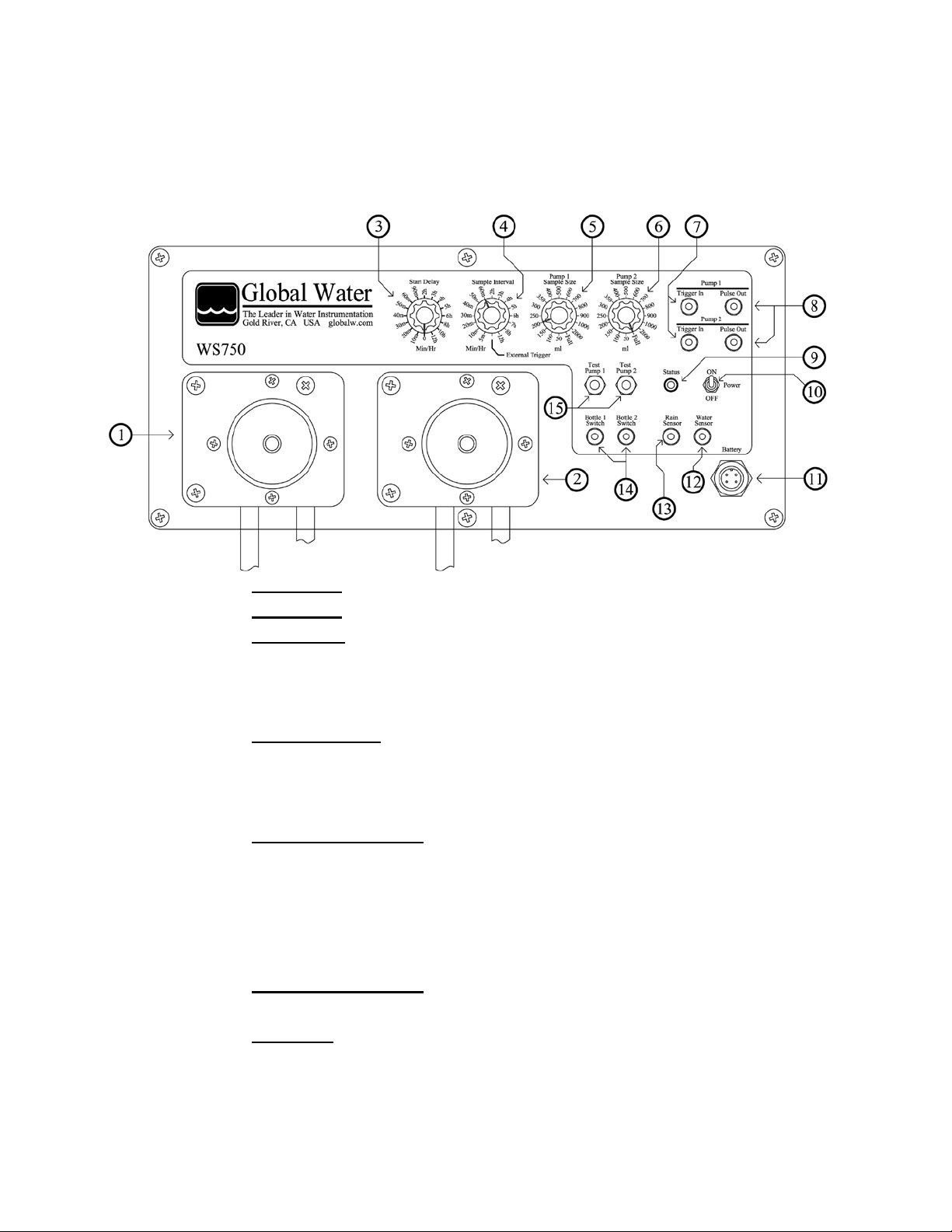
VI. The Control Panel
1. Pump One.
2. Pump Two.
3. Start Delay: This setting delays sampling by a preset amount of time. If
no delay is desired, set the control to zero. Only the first sam ple taken by
each pump is delayed, except as described lat er in the section titled
“External Trigger Mode”.
4. Sample Interval: Sets the time interval between composite samples. The
“External Trigger” position is res er v ed for using the Trigger and Rain
Sensor inputs to initiate sampling as described later in the section titled
“External Trigger Mode”.
5. Pump 1 Sample Size: Sets the siz e for a single com pos ite sample with
pump one. The sample size settings are approximat e and apply to a head
height of four feet. The switch position mark ed “Full ” causes the pump to
work as a discrete sampler, filling the bot tle full in one sample. Note: In
the “Full” position, the sampler will shut off the pump after one hour, even
if the bottle is not full.
6. Pump 2 Sample Size: Sets the sample siz e for pump two and works the
same as Pump 1 Sample Size described above.
7. Trigger In: These inputs work in “Ex ternal Trigger” mode only, when
selected by the Sample Interval cont r ol. A signal from an external device
will cause a single sample to be taken by the corresponding pump
according to its Size control. The Ext er nal Trigger m ode is des c r ibed in
Global Water
800-876-1172 • globalw.com
- 6 -
Page 7

Global Water
800-876-1172 • globalw.com
more detail later in the section titled “External Trigger Mode”. Refer to the
Specifications section for details about the input pulse requirements.
8. Pulse Out: These outputs send a pulse to an optional recording or
monitoring device each time t he c or r es ponding pump starts, allowing the
time of the sample event to be recorded. R efer to the Specifications
section for details about the out put pulse.
9. Status: This red LED indicates the status of the sampler. While the
sampler is waiting to be triggered, the light remains off. Once triggered,
the LED will blink once every two seconds while the Delay or Interval
timers are running and while the pumps are operating. The LED remains
lit constantly when both sample bottles ar e full or if the switches are not
plugged in.
10. Power: This turns the power to the sampler on and off. Turning the
switch off for one second resets all func tions and timers.
11. Battery: Connect the battery here using the supplied battery cable.
12. Water Sensor: When an optional wat er s ens or is plugged into this jack,
sampling will not begin until the presence of water is detected (the Rain
Sensor must also detect water). If this sens or input is not being used,
plug one of the two shorting plugs supplied with the sampler into this jack.
This input has no affect when triggering the sam pler with the Trigger
Inputs in External Trigger mode.
13. Rain Sensor: When an optional water sensor is plugged int o this jack,
sampling will not begin until the presence of water is detected, usually in a
rain gauge (the Water Sensor must also detect water). If this sensor input
is not being used, plug one of the two shorting plugs s upplied with the
sampler into this jack. This input has no aff ect when tr igger ing the
sampler with the Trigger Inputs in External Trigger mode. This input can
also be used to take individual composite samples and is described in
detail later in the section titled “External Trigger Mode”.
14. Bottle Switches: The sample bottle float s witches plug into the control
panel here. For sampling to occur, a float s witch must be plugged in and
the bottle must not be full. If the Status LED remains lit all the time, check
these connections.
15. Test Pump: Pressing one of these buttons tests the operation of the
corresponding pump. These buttons will test the pumps operation
regardless of whether a bottle swit c h is plugged in or not. The pump runs
forward for as long as the button is held down, then r ev er s es for an equal
amount of time, or 15 seconds, which ever is les s .
- 7 -
Page 8

Global Water
800-876-1172 • globalw.com
VII. Composite Sampling
A composite sample is a series of smaller s amples put into the same bottle, thus showing
an “average” sample over time. Set the Interval control to the desired time between
samples (do not select the External T r igger pos ition). Set the Size control for the
corresponding pump to the desired sample size. Note that the sample size settings are
approximate and apply to a head height of four feet . For heights other than four feet, refer
to the chart inside the front of the sampler. E ach pump c an hav e different size settings but
will share the same Sample Interval s etting.
The sampler starts timing when both of the optional Rain and Water Sensor s detect
moisture. If you do not have the optional water sensor s or do not need them for your
application, defeat them by plugging one of the two shorting plugs supplied with the s am pler
into their jack. If both inputs are defeated, the sampler starts up triggered when the power
switch is turned on. The Status LED starts blinking ever y 2 s ec onds onc e the sampler is
triggered.
The Start Delay tim er begins running when the sampler is triggered by the Rain and Water
Sensors and the first sample is taken when the timer ex pir es . If the Delay control is set to
zero, sampling begins immediately . The delay timer only applies to the first sample taken
by each pump. At the end of each sample, the pumps rev er s e for 15 seconds.
Sampling continues as Trigger-Delay-Sample-Reverse-Interval-Sample-Reverse-IntervalSample-Reverse … until the sample bot tles are full. For each pump, the same amount of
Interval time is placed between samples, ev en if the size settings are different. When both
bottles are full, the Status LED r em ains lit constantly.
VIII. Discrete Sampling
A discrete sample is a single sample put into the s ame bottle, thus being a sample at one
point in time. Set the Size control for the cor r espondin g pum p to “Full”. Once started, the
pump will continue to run until the sample bot tle if full.
As with composite sampling, the Start Delay timer begins when the sampler is trigger by the
Rain and Water Sensors and the first sample is tak en when the timer expires. If the Delay
control is set to zero, sampling begins immediately. The Status LED blinks every 2 s ec onds
while the delay timer or the pumps are running and remains lit constantly once both of the
sample bottles have been filled. At the end of sampling, the pumps reverse for 15 seconds.
- 8 -
Page 9

Global Water
800-876-1172 • globalw.com
IX. Mixed Sampling, Composite and Discrete Sampler
The WS750 Sampler can be configured as both a com pos ite and discrete sampler at the same time since each pump has a separate Size control. Set one pump’s size setting to the desired composite sample size and the other to “Full”.
Again, the Start Delay timer begins when the sampler is trigger by the Rain and Wat er
Sensors and the first sample is taken when the timer ex pir es . If the Delay control is set to
zero, sampling begins immediately. The Status LED blinks every 2 seconds while the delay
timer and the pumps are running and remains lit c ons tantly once both of the sample bottles
have been filled. At the end of each sample, t he pumps r ev er s e for 15 seconds.
X. External Trigger Mode
When the Sample Interval control is s et to the “External Trigger” position, the s am pler c an
be triggered externally by inputs fr om either the Trigger In jacks or the Rain Sensor input.
This mode is useful in applications where sampl ing oc c ur s bas ed on r eadings from a
process controller, SCADA system, flow monitor, auto-dumping rain gauge or other remote
monitoring devices.
Using the Rain Sensor as a trigger source:
This mode is normally used with an auto-dumping rain gauge that empties itself every 24
hours. Set the Sample Interval control to External Trigger. Set each pumps Size control
based on desired composite sample size or s et t o Full f or a dis c r ete sample.
The sampler will be triggered when both the Rain and W ater Sensors detect moisture. If the
Water Sensor is not needed, use one of the shorting plugs supplied with the sampler to
defeat it by plugging it into the Water S ens or input jack . Place the Rain Sensor at the
desired height in the rain gauge. When t he Rain Sensor detects moisture, the sampler will
start.
Once triggered by the Rain Sensor, the Start Delay timer begins running and the Status
LED begins blinking every 2 seconds. When the tim er ex pir es , the pumps take a sample
based on their individual Size settings. When the samples are complete, the pumps reverse
for 15 seconds, then stop. The sampler cannot be re-trigger ed until the rain gauge empties
itself and the Rain Sensor goes dry. The next t ime t he s ens or detects moisture, the Start
Delay timer will start over again and another sample will be taken when it expires.
- 9 -
Page 10

Global Water
800-876-1172 • globalw.com
If a pump’s Size control is set to take a full-bottle discrete sample, f urther triggers will have
no affect on that pump. If a pump is set to take composite samples, each one will repres ent
the conditions at the time of that “qualifi ed r ain ev ent”. This process will continue until both
the sample bottles are full and the Status LED remains lit all the time.
Using the Trigger Inputs as a source:
These inputs are generally used for connecting to a flow monitor, processor controller, or
other external monitoring device.
When using the Trigger In input jacks, leave the Rain Sensor input jack disconnected. Each
of the two Trigger Inputs control the c or r es ponding pump separately from the other.
Upon being triggered by one of the Trigger Inputs, the Start Delay timer begins runnin g.
When the delay timer has expired, the corr es ponding pump t ak es a s am ple bas ed on its
Size setting. Holding the Trigger Input active past the end of the sam ple will cause the
pump to continue until the Trigger Input is r eleas ed. When the sample is complete, the
pump reverses, and then stops.
Flow Proportional Sampling
a. To set the WS750 up to take flow proportional samples , a flow monitor must
be attached to the control panel. In t his c onfiguration, the sampler is
designed to take a sample every time a specific amount of flow has passed
through the flow monitor.
b. The flow monitor must provide a momentary s witch c los ur e ( 250ms or longer)
or a pulse of 4-30VDC, whenever a sample is to be taken. The output of the
flow monitor must be wired to a 2-wire RCA jack as show n in A ppendix C.
The phone plug is then inserted into the Tr igger In jack on the control panel.
c. Set the Sample Interval knob to External Trigger mode and the Sample Size
knob to the desired sample size. The sample will be taken, flow
proportionally, as directed by the flow meter.
- 10 -
Page 11

XI. Specifications
Operating Temperature: 0° to +70°C
Size of unit: 22”H X 17"W X 9"D
Weight: 22lb (Shipping Weight 24lb)
Materials:
Enclosure: Expanded UV protected PVC
Bottles: Two 1 gallon Polyethylene
Pickup Hose: 15' nylon reinforced 1/4" ID polyethylene
Pump Tubing: Neoprene 1/4" ID, 7/16” OD
Sample Pumps:
Flow Rate: 1000 ml per minute at 4 ft. head
Type: Peristaltic
Maximum Lift: ~20 feet
Battery: Rechargeable 5 AH Gel Cell
Battery Life: One Pump running: ~1 hour
Start Delay: 16 time settings from 0 to 12 hours
Composite Interval: 15 time settings from 5 min. to 12 hours
Sample Size: 15 composite sample sizes from 50ml to
External Trigger Inputs: 250mS minimum pulse width
Pulse Outputs: 5VDC one-second pulse
1000ohm output impedance
Bottle Switch Inputs: Switch closure Input
Floating read switch in bottle
Rain and Water Sensors: Optional moisture sensors or switch
Internal Fuse: 10A Slow-Blow
Global Water
800-876-1172 • globalw.com
flexible tubing section with int ak e s trainer
Two Pumps running: ~ ½ hour
Standby: 3 months while still retaining
power to run both pumps to capacity
plus an External Trigger mode sett ing
2 liters plus a Full Bottle discrete setting
(Approximate sizes at 4 foot head)
Switch closure or 4-30VDC
closure inputs
- 11 -
Page 12

XII. Maintenance
Sampler
a. The Global Water WS750 Water Sampler requires minimal m aintenance.
The sampler enclosure is rainproof and rugged. Avoid exposure to extremely
rough usage. Routinely wipe the carry ing c as e and contr ol panel face, rinse
the pickup hose and debris strainer, and wash the sample bottles with mild
soap and warm water. Additional plastic and glass s am ple bottles, neoprene
tubing for the sampler pump, bottle caps /f loat switches, removable debris
strainers, and pickup hose can be purchased from Global Water (see
Appendix C section).
Battery
b. If the pump runs slowly, this is an indication t hat t he battery requires
recharging. Global Water recomm ends fully recharging batteries
approximately once per month. In addition, the battery should be recharged
before any extended use. NOTE: The battery life will las t longer if recharged
before it drains below 10.5 volts.
Global Water
800-876-1172 • globalw.com
c. To recharge the battery, disconnect the battery cable from the battery.
Remove the battery from the
enclosure. Attach the battery
charger’s spade lugs to the
battery terminals, red lug to red
terminal, and blue lug to black
terminal. Plug the charger into
a wall socket. A full recharge
will take about 12 hours.
Charging more than 24 hours
may shorten the battery life.
Additional batteries and batt er y
chargers are available from
Global Water (see Appendix C section).
- 12 -
Page 13

XIII. Troubleshooting
a. Check that the battery is firmly connected to the control panel and confirm
that it is fully charged.
b. Press the Pump Test buttons on the front panel. The test buttons should
always run the pumps, regardless of the s tate of any of the inputs.
c. Tur n the power switch off for 1-2 seconds then back on to reset the sampler.
d. Check the Status LED on the front panel.
i. The LE D is off: If the water sensors are being used, check the Rain
and Water Sensor inputs. Sensors must be in contact with moisture
and unused inputs must have one of the shorting plugs supplied with
the sampler plugged into the jack. If the Trigger Inputs are being used,
confirm that External Trigger mode is s elec ted on the Interval control.
Check the pulses coming from the tr igger ing dev ic e and c onfirm they
meet specifications. Test the Trigger Inputs by plugging one of the
shorting plugs supplied with the sampler into the jack.
ii. The LE D is blinking: Check the Start Delay and Interval settings . The
sampler may be waiting for the Delay timer to run out or it may be
timing the interval between composite samples.
iii. The LE D is on c ons tantly: Check the bottle switches. The light
remains on when both sample bottles are f ull or when both float
switches are not plugged in or working properly. Plug one of the
shorting plugs supplied with the sampler into one of the bottle switch
jacks, the light should go out or st art blink ing.
Other issues
e. Call us for tech support: 800-876-1172 or (979) 690-5560 ( many problems
can be solved over the phone). Fax: (979) 690-0440 or Em ail:
globalw@globalw.com.
Be prepared to describe the problem being experienced inc luding specific
details of the application and installation and any additional pertinent
information.
f. In the event that the equipment needs to be returned to the factory f or any
reason, please call to obtain a RMA # (Return Material Authorization). Do not
return items without a RMA # on the outside of the package.
Global Water
800-876-1172 • globalw.com
- 13 -
Page 14

Global Water
800-876-1172 • globalw.com
Decontaminate the WS750 prior to returning.
Include a written statement descr ibing the problems.
Send the package with shipping prepaid to G lobal Water’s factory address.
Insure the shipment, as the warranty does not cover damage incurred during
transit.
g. When calling for tech support, please have t he following information ready;
1. Model #.
2. Unit serial number.
3. P.O.# the equipment was purchased on.
4. Global Water’s sales number or the invoice num ber .
5. Repair instructions and/or specif ic pr oblems relating to the product.
IXV. Warranty
a. Global Water Instrumentation, Inc. warrants that its products are free from
defects in material and workmanship under normal use and service for a
period of one year from date of shipment from factory. Global Water’s
obligations under this warranty ar e lim ited to, at Global Water’s option: (I)
replacing or (II) repairing; any produc ts determined to be defective. In no
case shall Global Water’s liability exceed t he pr oduc ts original purchase price.
This warranty does not apply to any equipment that has been repaired or
altered, except by Global Water Inst r um entation, Inc., or which has been
subject to misuse, negligence or accident. It is expressly agreed that this
warranty will be in lieu of all warranties of fitness and in lieu of the warranty of
merchantability.
b. The warranty begins on the date of the product’s invoice.
- 14 -
Page 15

Actual Sample Size vs. Sample S ize Control for Various Hea d He ights
0
200
400
600
800
1000
1200
1400
1600
1800
2000
0 250 500 750 1000 1250 1500 1750 2000 2250
Actual Sample Size (ml)
Sample Size Control Setting (ml)
14 Feet
2 Feet
Global Water
800-876-1172 • globalw.com
Appendix A: Sample Size vs. Head He ight
Use the following graph to see how sample s iz e changes with head height. The Sample
Size controls on the control panel are calibrated at a height of 4 feet. Increasing the head
height decreases the sample size by a predictable amount. To determine the appropriate
Sample Size setting for a desired volume; find the sample size on the horizontal axis, follow
straight up to the line corresponding to your head height, then look across to the vertic al
axis and read the setting for the Size control on the control panel.
- 15 -
Page 16

Global Water
800-876-1172 • globalw.com
Appendix B: Battery Life
While battery life depends on several f ac tors such as charge, condition and temperature; it
can generally be assumed that the sampler c an deployed in the field for more than 3
months waiting to be triggered, while still r etaining enough charge to run a single pump for
one hour (about 10 gallons) or both pumps f or ½ hour (5 gallons) . To prevent large current
surges which occur when the pumps first turn on, the WS750 is designed so that only one
pump will turn on or off at a time. A ½ second time delay is inserted between these events,
extending the life of the charge and the life of the battery.
Appendix C: Input and Output Connection
- 16 -
Page 17

Part Description
Part Number
Unit
12V 5Ah Battery
00-010
Each
Battery Charger
FE0400
Each
1 Gal Plastic Sample Bottle
00-418
Each
Bottle Cap/Float Switch
CB0200
Each
Pickup Hose
00-546
Feet
Pickup Stra iner
CA0300
Each
Pump tubing
00-744
Feet
Rain and Water Sensors
CA0400
Each
Auto-Drain Rain Gauge
CH0000
Each
Appendix D: Accessories
Global Water
800-876-1172 • globalw.com
- 17 -
 Loading...