

Page 1
Operating manual
Logger WQL-Cond
PC program WQL-Log
Logger for conductivity measurement and PC program
to display and evaluate data from the logger
ba75822de01 03/2011
DRAFT: Thursday, 17. March 2011
Page 2

Note
The latest version of the present operating manual can be found on the
Internet under www.WTW.com.
Copyright © Weilheim 2011, WTW GmbH
Reproduction in whole - or even in part - is prohibited without the
express written permission of WTW GmbH, Weilheim.
Printed in Germany.
Page 3

WQL-Cond Contents
Contents
1 Overview . . . . . . . . . . . . . . . . . . . . . . . . . . . . . . . . . . . . . . . . . . . . . . . . . . . . . . . . . . . 101
1.1 Logger WQL-Cond . . . . . . . . . . . . . . . . . . . . . . . . . . . . . . . . . . . . . . . . . . . . . . . . . . . . . 101
1.2 PC program WQL-Log . . . . . . . . . . . . . . . . . . . . . . . . . . . . . . . . . . . . . . . . . . . . . . . . . . 102
2 Safety . . . . . . . . . . . . . . . . . . . . . . . . . . . . . . . . . . . . . . . . . . . . . . . . . . . . . . . . . . . . . 105
3 Commissioning . . . . . . . . . . . . . . . . . . . . . . . . . . . . . . . . . . . . . . . . . . . . . . . . . . . . . 107
3.1 Inserting the battery . . . . . . . . . . . . . . . . . . . . . . . . . . . . . . . . . . . . . . . . . . . . . . . . . . . .107
3.2 Mounting suspension . . . . . . . . . . . . . . . . . . . . . . . . . . . . . . . . . . . . . . . . . . . . . . . . . . . 108
3.3 Installing the WQL-Log program . . . . . . . . . . . . . . . . . . . . . . . . . . . . . . . . . . . . . . . . . . . 109
3.3.1 PC requirements . . . . . . . . . . . . . . . . . . . . . . . . . . . . . . . . . . . . . . . . . . . . . . . 109
3.3.2 Installation routine . . . . . . . . . . . . . . . . . . . . . . . . . . . . . . . . . . . . . . . . . . . . . . 109
3.4 Initial commissioning . . . . . . . . . . . . . . . . . . . . . . . . . . . . . . . . . . . . . . . . . . . . . . . . . . 115
3.5 Connection types . . . . . . . . . . . . . . . . . . . . . . . . . . . . . . . . . . . . . . . . . . . . . . . . . . . . . .118
3.6 Starting the WQL-Log program . . . . . . . . . . . . . . . . . . . . . . . . . . . . . . . . . . . . . . . . . . . 119
4 Setting the display . . . . . . . . . . . . . . . . . . . . . . . . . . . . . . . . . . . . . . . . . . . . . . . . . . . 121
4.1 Setting the language . . . . . . . . . . . . . . . . . . . . . . . . . . . . . . . . . . . . . . . . . . . . . . . . . . . . 121
4.2 Setting the temperature unit . . . . . . . . . . . . . . . . . . . . . . . . . . . . . . . . . . . . . . . . . . . . . . 121
4.3 Setting the cursor . . . . . . . . . . . . . . . . . . . . . . . . . . . . . . . . . . . . . . . . . . . . . . . . . . . . . .122
5 Setting the measuring mode . . . . . . . . . . . . . . . . . . . . . . . . . . . . . . . . . . . . . . . . . . . 124
6 Calibration in control standard (determining the cell constant) . . . . . . . . . . . . . . 127
6.1 Calibration settings . . . . . . . . . . . . . . . . . . . . . . . . . . . . . . . . . . . . . . . . . . . . . . . . . . . . .128
6.2 Calibrating (automatic) . . . . . . . . . . . . . . . . . . . . . . . . . . . . . . . . . . . . . . . . . . . . . . . . . . 129
6.3 Calibrating (manual) . . . . . . . . . . . . . . . . . . . . . . . . . . . . . . . . . . . . . . . . . . . . . . . . . . . . 132
6.4 Viewing the calibration history . . . . . . . . . . . . . . . . . . . . . . . . . . . . . . . . . . . . . . . . . . . . 136
6.5 Exporting the calibration history . . . . . . . . . . . . . . . . . . . . . . . . . . . . . . . . . . . . . . . . . . . 138
7 Measuring directly . . . . . . . . . . . . . . . . . . . . . . . . . . . . . . . . . . . . . . . . . . . . . . . . . . . 139
8 Logging . . . . . . . . . . . . . . . . . . . . . . . . . . . . . . . . . . . . . . . . . . . . . . . . . . . . . . . . . . . . 140
8.1 Typical sequence of a logging job (checklist) . . . . . . . . . . . . . . . . . . . . . . . . . . . . . . . . . 140
8.2 Setting up a logging job - setting parameters . . . . . . . . . . . . . . . . . . . . . . . . . . . . . . . . . 141
8.3 Setting the parameters and starting the logging job . . . . . . . . . . . . . . . . . . . . . . . . . . . . 144
8.4 Logging job - storing or loading the configuration . . . . . . . . . . . . . . . . . . . . . . . . . . . . . . 151
8.5 Signal LED and logger key button . . . . . . . . . . . . . . . . . . . . . . . . . . . . . . . . . . . . . . . . . 153
8.5.1 Signal LED to indicate the operating conditions of the logger . . . . . . . . . . . . 153
8.5.2 Logger key button . . . . . . . . . . . . . . . . . . . . . . . . . . . . . . . . . . . . . . . . . . . . . . 153
8.6 Importing data . . . . . . . . . . . . . . . . . . . . . . . . . . . . . . . . . . . . . . . . . . . . . . . . . . . . . . . . . 154
8.7 Overview of the data window . . . . . . . . . . . . . . . . . . . . . . . . . . . . . . . . . . . . . . . . . . . . . 155
8.8 Managing the logging jobs . . . . . . . . . . . . . . . . . . . . . . . . . . . . . . . . . . . . . . . . . . . . . . . 156
ba75822e01 03/2011
99
Page 4

Contents WQL-Cond
9 Working with the database and measurement data . . . . . . . . . . . . . . . . . . . . . . . . 159
9.1 General information on the database . . . . . . . . . . . . . . . . . . . . . . . . . . . . . . . . . . . . . . . 159
9.2 Creating a database . . . . . . . . . . . . . . . . . . . . . . . . . . . . . . . . . . . . . . . . . . . . . . . . . . . . 160
9.3 Opening a database . . . . . . . . . . . . . . . . . . . . . . . . . . . . . . . . . . . . . . . . . . . . . . . . . . . . 161
9.4 Backing up a database . . . . . . . . . . . . . . . . . . . . . . . . . . . . . . . . . . . . . . . . . . . . . . . . . 162
9.5 Restoring a database . . . . . . . . . . . . . . . . . . . . . . . . . . . . . . . . . . . . . . . . . . . . . . . . . . . 163
9.6 Erasing a database . . . . . . . . . . . . . . . . . . . . . . . . . . . . . . . . . . . . . . . . . . . . . . . . . . . . 165
9.7 Querying data . . . . . . . . . . . . . . . . . . . . . . . . . . . . . . . . . . . . . . . . . . . . . . . . . . . . . . . . 166
9.8 Exporting data . . . . . . . . . . . . . . . . . . . . . . . . . . . . . . . . . . . . . . . . . . . . . . . . . . . . . . . . 170
10 Info menus . . . . . . . . . . . . . . . . . . . . . . . . . . . . . . . . . . . . . . . . . . . . . . . . . . . . . . . . . .174
10.1 Database information . . . . . . . . . . . . . . . . . . . . . . . . . . . . . . . . . . . . . . . . . . . . . . . . . . . 174
10.2 Device information . . . . . . . . . . . . . . . . . . . . . . . . . . . . . . . . . . . . . . . . . . . . . . . . . . . . . 175
10.3 Program info . . . . . . . . . . . . . . . . . . . . . . . . . . . . . . . . . . . . . . . . . . . . . . . . . . . . . . . . . 176
11 Resetting the logger . . . . . . . . . . . . . . . . . . . . . . . . . . . . . . . . . . . . . . . . . . . . . . . . . . 177
12 Maintenance, cleaning, storage . . . . . . . . . . . . . . . . . . . . . . . . . . . . . . . . . . . . . . . . . 179
12.1 General maintenance instructions . . . . . . . . . . . . . . . . . . . . . . . . . . . . . . . . . . . . . . . . . 179
12.2 Exterior cleaning . . . . . . . . . . . . . . . . . . . . . . . . . . . . . . . . . . . . . . . . . . . . . . . . . . . . . . 179
12.3 Battery . . . . . . . . . . . . . . . . . . . . . . . . . . . . . . . . . . . . . . . . . . . . . . . . . . . . . . . . . . . . . . 180
12.3.1 Battery service life . . . . . . . . . . . . . . . . . . . . . . . . . . . . . . . . . . . . . . . . . . . . . 180
12.3.2 Ascertaining the battery status . . . . . . . . . . . . . . . . . . . . . . . . . . . . . . . . . . . . 180
12.3.3 Resetting the battery counter . . . . . . . . . . . . . . . . . . . . . . . . . . . . . . . . . . . . . 181
12.3.4 Battery replacement . . . . . . . . . . . . . . . . . . . . . . . . . . . . . . . . . . . . . . . . . . . . 182
12.4 Storage . . . . . . . . . . . . . . . . . . . . . . . . . . . . . . . . . . . . . . . . . . . . . . . . . . . . . . . . . . . . . 183
12.5 Replacement parts . . . . . . . . . . . . . . . . . . . . . . . . . . . . . . . . . . . . . . . . . . . . . . . . . . . . . 183
13 What to do if... . . . . . . . . . . . . . . . . . . . . . . . . . . . . . . . . . . . . . . . . . . . . . . . . . . . . . . . 185
13.1 Calibration and measuring . . . . . . . . . . . . . . . . . . . . . . . . . . . . . . . . . . . . . . . . . . . . . . . 185
13.2 Communication of the logger and PC program . . . . . . . . . . . . . . . . . . . . . . . . . . . . . . . 186
13.3 Communication between PC program and SQL server . . . . . . . . . . . . . . . . . . . . . . . . . 186
14 Technical data . . . . . . . . . . . . . . . . . . . . . . . . . . . . . . . . . . . . . . . . . . . . . . . . . . . . . . . 187
14.1 Measurement characteristics . . . . . . . . . . . . . . . . . . . . . . . . . . . . . . . . . . . . . . . . . . . . . 187
14.2 Application characteristics . . . . . . . . . . . . . . . . . . . . . . . . . . . . . . . . . . . . . . . . . . . . . . . 188
14.3 General data . . . . . . . . . . . . . . . . . . . . . . . . . . . . . . . . . . . . . . . . . . . . . . . . . . . . . . . . . 188
14.4 Electrical data . . . . . . . . . . . . . . . . . . . . . . . . . . . . . . . . . . . . . . . . . . . . . . . . . . . . . . . . 189
100
ba75822e01 03/2011
Page 5
WQL-Cond Overview
Control panel
1
2
3
4
5
6
9
7
8
10 11
12
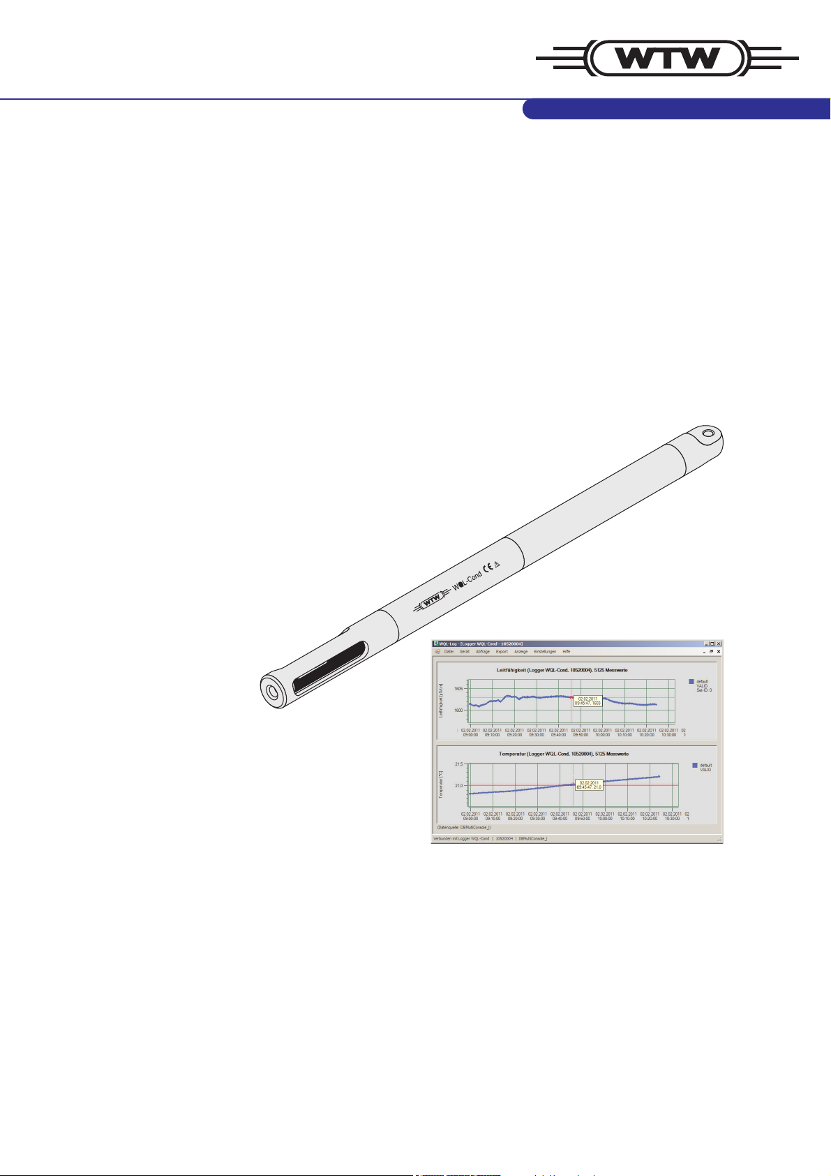
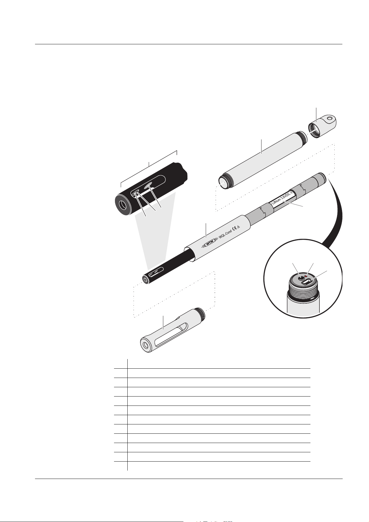
1 Overview
1.1 Logger WQL-Cond
Structure of the
logger
1 Protective hood
2 Conductivity measuring cell (permanently installed)
3 Voltage electrode (inside, 2x)
4 Current electrode (ring, 2x)
5 Temperature sensor in graphite enclosure
6 Shaft
7 Sleeve
8 Cap
9 Battery compartment with battery
10 Key button
11 Signal LED
12 USB socket
ba75822e01 03/2011
101
Page 6

Overview WQL-Cond
Recommended
fields of
application
Conductivity measurements in wells, bore holes, rivers, water bodies and
other surface water, drinking water, ground water, leachate, waste water.
1.2 PC program WQL-Log
The WQL-Log PC program serves to operate a connected WTW data logger
of the WQL series type. The WQL-Log PC program automatically recognizes
the logger when it is connected to the USB interface and controls the menus
according to the type and measured parameter.
The PC program can carry out the following functions:
z Calibrate the measuring system
z Set up and start a logging job
z Measure directly: The logger is connected to the PC via USB and the PC
program displays the current measured values.
z Read in measurement data of the logging job: Consistent data copying to
a PC-based database.
z Database-supported evaluation of measurement data, export functions
Note
The current version of the WQL-Log PC program and the current firmware
for the WQL-Cond logger is available on the Internet on the website of the
manufacturer of your meter.
102
ba75822e01 03/2011
Page 7
WQL-Cond Overview
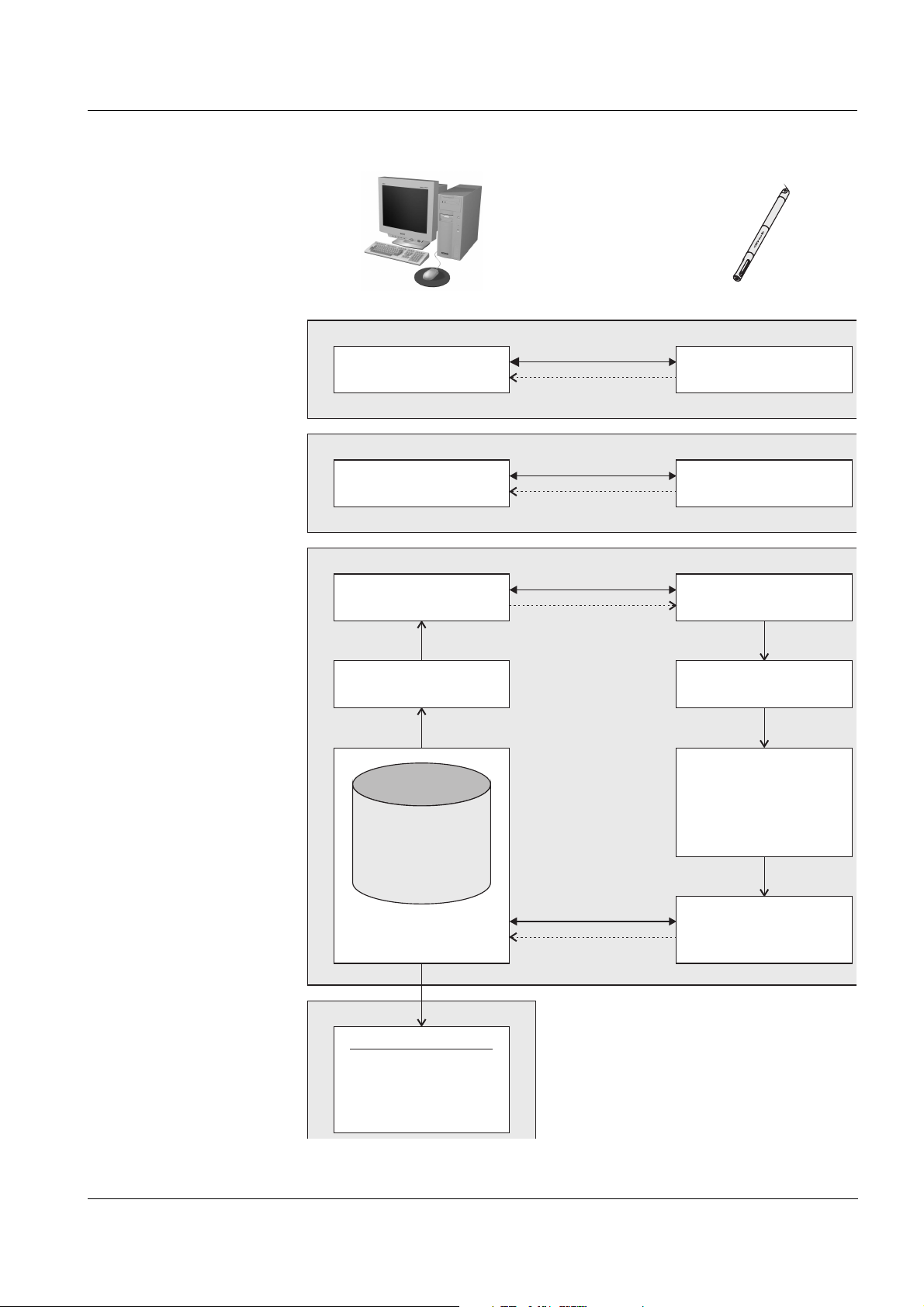
Logger
Carry out logging jobSet up logging jobLogging
(chapter 6)
Processing the
measurement
data
(chapter 7)
Calibrate in
standard solution
Stop
(e.g. logging job
completed)
(Log)
Measurement dataset 1
Measurement dataset 2
Measurement dataset 3
...
Measurement dataset 1
Measurement dataset 2
Measurement dataset 3
...
Measurement dataset n
Connect
Connect
Connect
Connect
Calibration record
Current values
(real time)
Parameterize,
send
Read in completed
logging job
PC + WQL-Log
CalibrateCalibrating
(chapter 4)
Measure directlyMeasuring
(chapter 5)
Measure
Stop communication
with WQL-Log
Clear the
logger memory
Measurement data
- Query
- Display
- Export (*.csv)
Save in database
ba75822e01 03/2011
Fig. 1-1 Overview of the communication of the logger and PC program
103
Page 8

Overview WQL-Cond
104
ba75822e01 03/2011
Page 9
WQL-Cond Safety
2 Safety
This component operating manual contains special instructions that must be
followed during the operation of the logger and PC program.
Always keep this operating manual in the vicinity of the logger and PC
program.
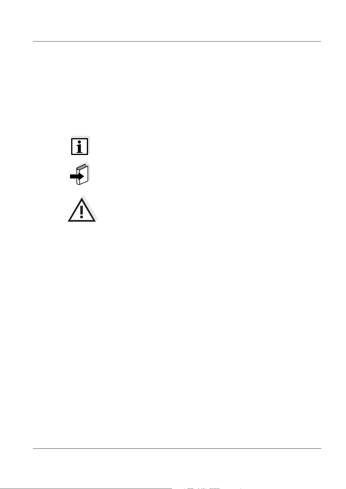
Symbols
used
Note
indicates notes that draw your attention to special features.
Note
indicates cross-references to other documents, e.g. application reports.
Warning
indicates instructions that must be followed precisely in order to avoid the
possibility of slight injuries or damage to the instrument or the environment.
ba75822e01 03/2011
105
Page 10

Safety WQL-Cond
106
ba75822e01 03/2011
Page 11
WQL-Cond Commissioning
1
3
2
3 Commissioning
Note
z Normally, all screw joints of the logger housing can be opened and closed
by hand, without using any tools. If necessary, use a paper towel so you
can get a better grip on the parts.
z Insert the battery in a clean and preferably dry environment.
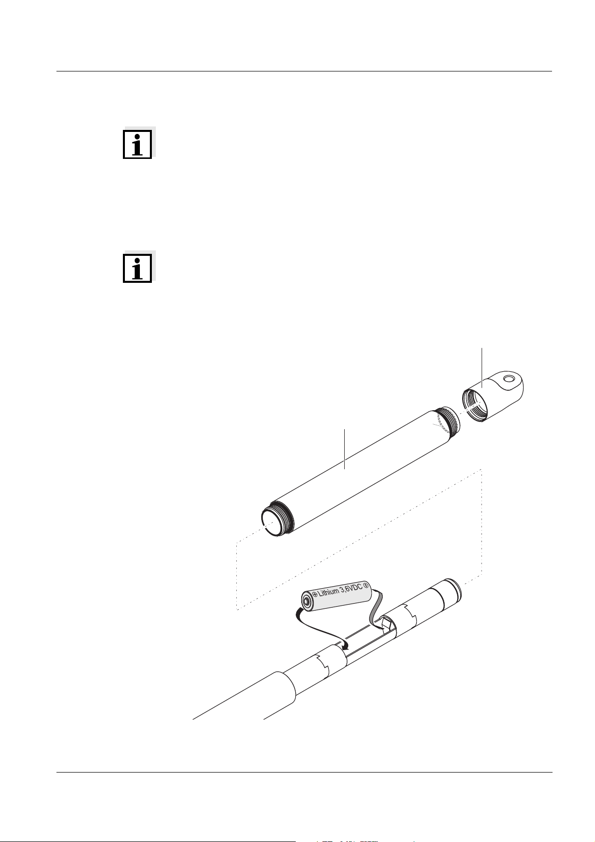
3.1 Inserting the battery
Note
The logger is powered by a 3.6 V lithium battery, size AA, as provided in the
scope of the delivery (see chapter 14 T
same size such as alkaline manganese batteries do not provide the required
operational voltage.
Operating time, see section 12.3 B
ECHNICAL DATA). Other batteries of the
ATTERY.
Fig. 3-1 Inserting the battery
ba75822e01 03/2011
107
Page 12

Commissioning WQL-Cond
1 Unscrew the cap (Pos. 1 in Fig. 3-1).
2 Unscrew the sleeve (Pos. 2).
3 Insert the battery. When doing so, make sure that the battery is
correctly positioned (see label in the battery compartment).
Corrosion
protection
4 Screw the sleeve on the shaft with the shorter
thread. At the rear end
of the sleeve there is a thin O-ring inside (Pos. 3). Make sure that this
O-ring is evenly positioned in the groove and is not twisted.
5 Screw on the sleeve and cap again. In the screwed condition, no gap
may be visible at the joints.
After the battery was inserted the signal LED lights up for 2 seconds. This
means the logger has to be connected with the PC to set the date and time
(see section 8.3 S
and section 8.5 S
ETTING THE PARAMETERS AND STARTING THE LOGGING JOB
IGNAL LED AND LOGGER KEY BUTTON).
3.2 Mounting suspension
To attach the logger to a rope or chain, a suitable shackle is provided whose
bolt fits through the cross hole in the cap. As an alternative, you can screw
some different sling gear into the M6 threaded hole at the cap end (e.g. M6
eye bolt).
In water, metal (e.g. zinc-plated) parts of the mounting suspension such as
thimbles, shackles or swivel connectors create voltages (chemically caused
according to the electrochemical series), which can cause corrosion of the
stainless steel of the logger or the above mentioned suspension parts.
Lightning
protection
Electrically conductive ropes or chains harbor the danger of the logger being
damaged by lightning.
Recommendation For reasons of corrosion and lightning protection, we recommend to use a
nonconductive suspension, e.g. one with low-wear, resistant polypropylene
ropes.
108
ba75822e01 03/2011
Page 13
WQL-Cond Commissioning
3.3 Installing the WQL-Log program
3.3.1 PC requirements
The WQL-Log software program requires the following system components:
Hardware
requirements
z Computer with Intel or Pentium III 500 MHz processor or higher
(1 GHz or quicker recommended.)
z At least 192 MB RAM (512 MB recommended)
z Hard disk with at least 600 MB available memory
z CD-ROM drive
z A free USB interface. Only one logger can be connected. If a new logger
is registered, the previous one is logged off.
Software
requirements
z 32-bit
-operating system Windows 7, Windows Vista, Windows XP,
Windows Server 2003 and higher or Windows 2000 Service Pack 4
User rights z Administrator rights are required for the initial installation. Contact your
system administrator if necessary.
Note
The program WQL-Log stores the database files with the stored data in the
directory where the SQL server is installed (because of access
authorization), i.e. normally on C:\. Make sure that there is enough storage
capacity available on the hard disk for this directory. An empty database
requires 3 MB storage space, a database with 50,000 datasets requires
approx. 7 MB storage space. A database can be max. 4 GB, containing
approx. 12.5 million datasets.
3.3.2 Installation routine
Note
The software is continuously developed further. The current version of the
WQL-Log program is available for download on the Internet under http://
www.WTW.com.
Note
The following files and/or directories are on the supplied CD-Rom:
z The installation file for the PC program and the database server
z A directory with the installation program for the driver of the USB
interface
z A directory with the operating manual for the logger and the PC program.
ba75822e01 03/2011
109
Page 14
Commissioning WQL-Cond
1 Insert the enclosed CD-Rom in the corresponding disk drive of the
PC.
Installing the
driver
Installing the PC
program and
database server
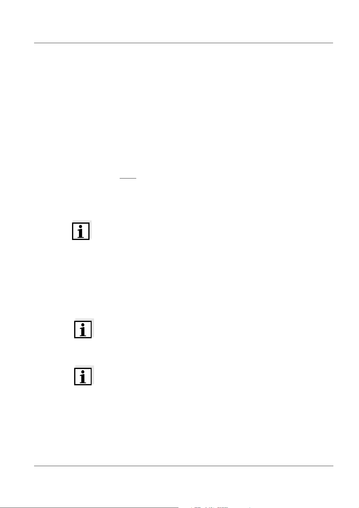
2 Open the directory, USB_VCP_driver.
3 Execute the file, CP210xVCPInstaller with a double click.
4 Follow the user guidance (click Install).
5 Confirm the installation with OK. A virtual COM Port has been created
with the installation.
6 Execute the WQLLog_Vxxxx.exe file with a double click (xxxx =
current version number).
The installation wizard appears.
110
7 Follow the user guidance (click OK).
ba75822e01 03/2011
Page 15
WQL-Cond Commissioning
Note
If the SQL server was already installed for another application, the
installation of the server is automatically skipped. The program continues
with step 15.
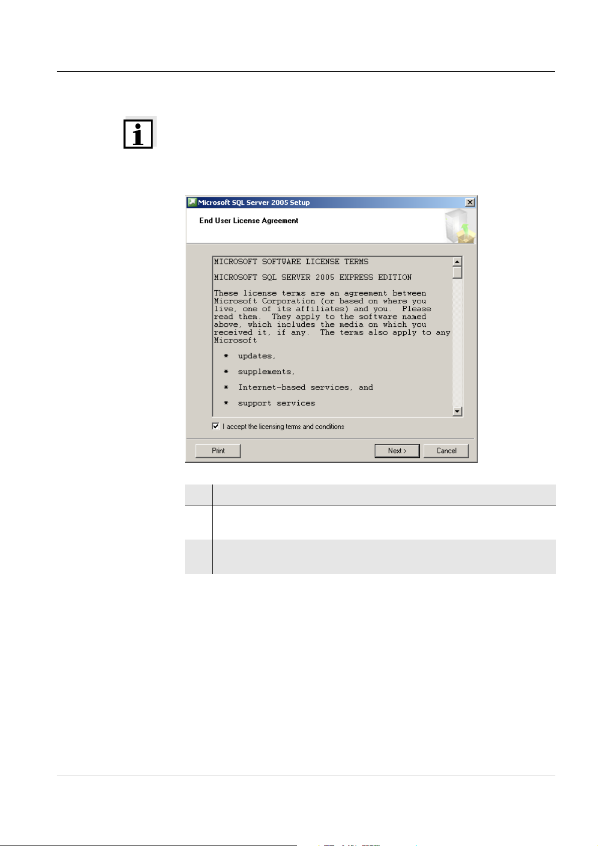
8 Check off the checkbox, I accept the licensing terms and conditions.
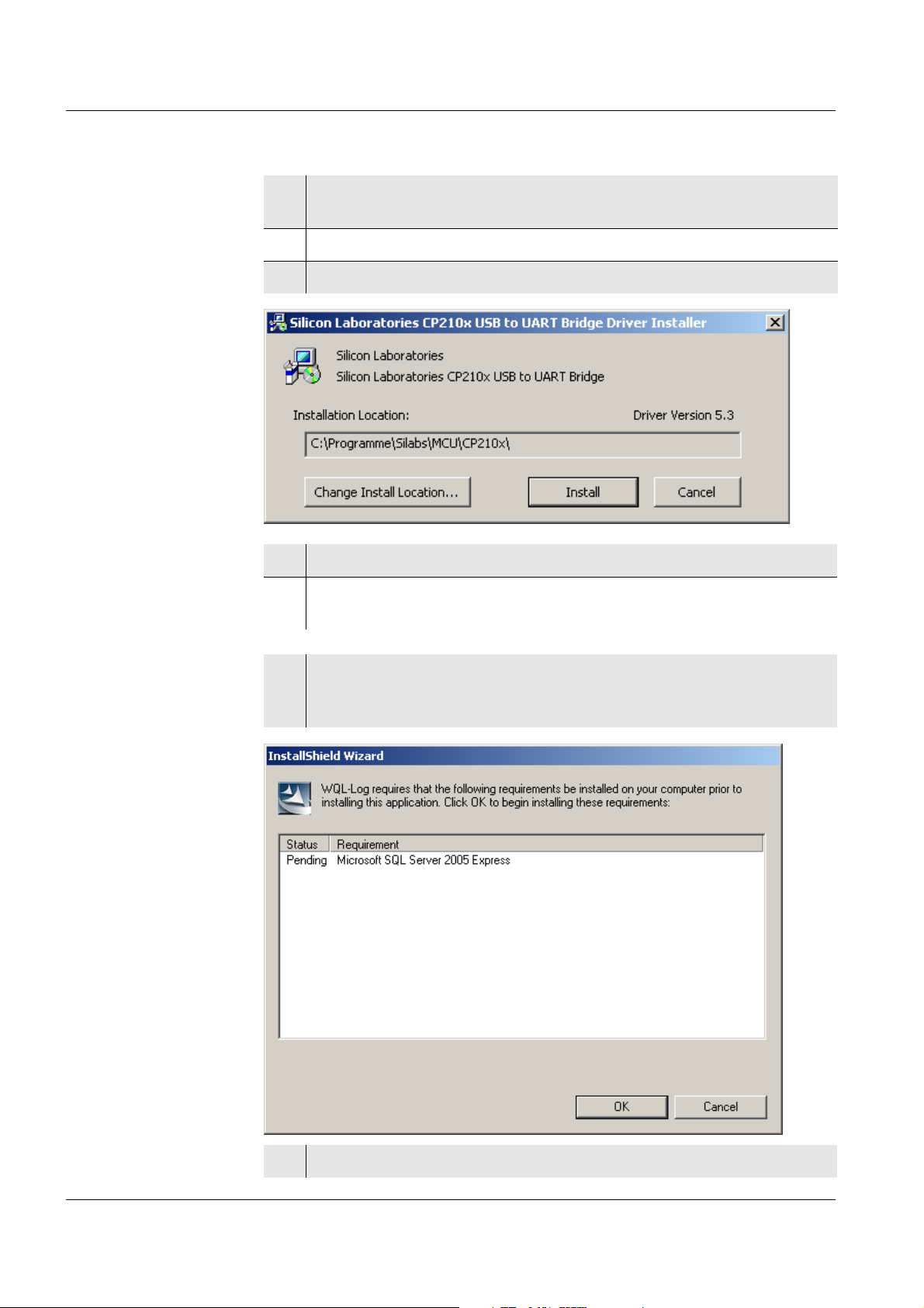
9Click Next. An information window appears with the components
required for the installation.
10 Click Install. The installation is carried out. Follow the user guidance
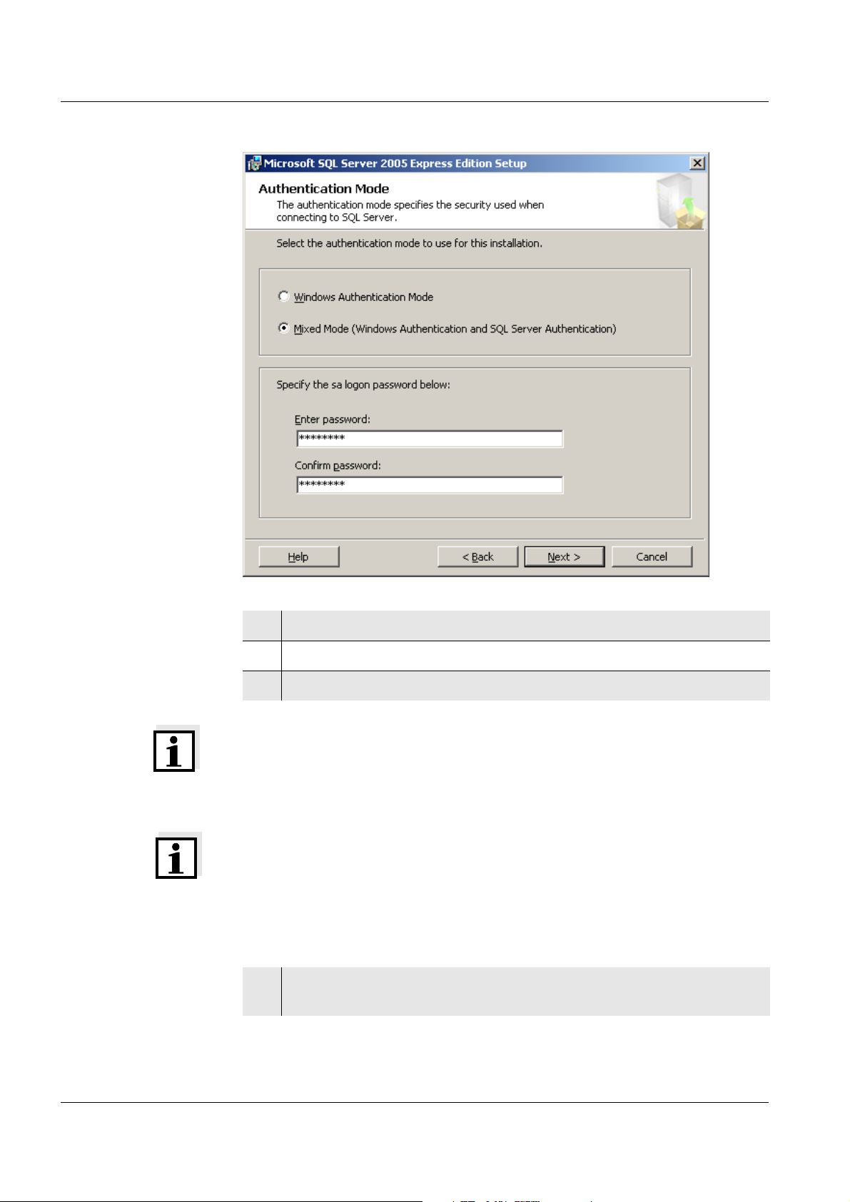
(click Next) until the Authentication Mode window appears.
ba75822e01 03/2011
111
Page 16
Commissioning WQL-Cond
11 Select the Mixed Mode option.
12 In the Enter password field, enter the password WTW!2009.
13 Repeat the password entry WTW!2009 in the Confirm password field.
Note
The password WTW!2009 must be entered twice. If a different password is
entered, the PC program is not granted access to the database.
Note
If the SQL server was already installed for another application, you have to
change the password for the SQL server first before the WQL-Log program
can create a database. To change the password see section
13.3 C
OMMUNICATION BETWEEN PC PROGRAM AND SQL SERVER.
14 Click Next. Then follow the user guidance (the default settings should
not be changed) until the following display appears:
112
ba75822e01 03/2011
Page 17
WQL-Cond Commissioning
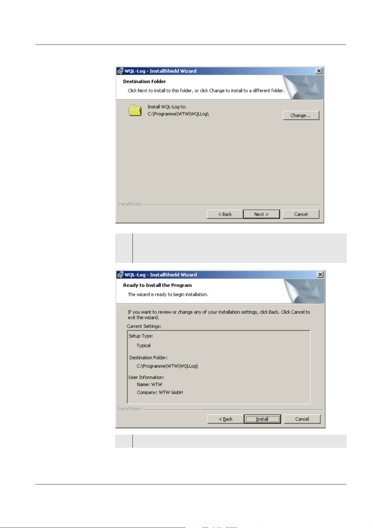
15 Here you can change the location where the PC program should be
stored (click Change... ).
When the required location is displayed, click Next.
ba75822e01 03/2011
16 Here you find information on the installation. Click Install.
113
Page 18
Commissioning WQL-Cond
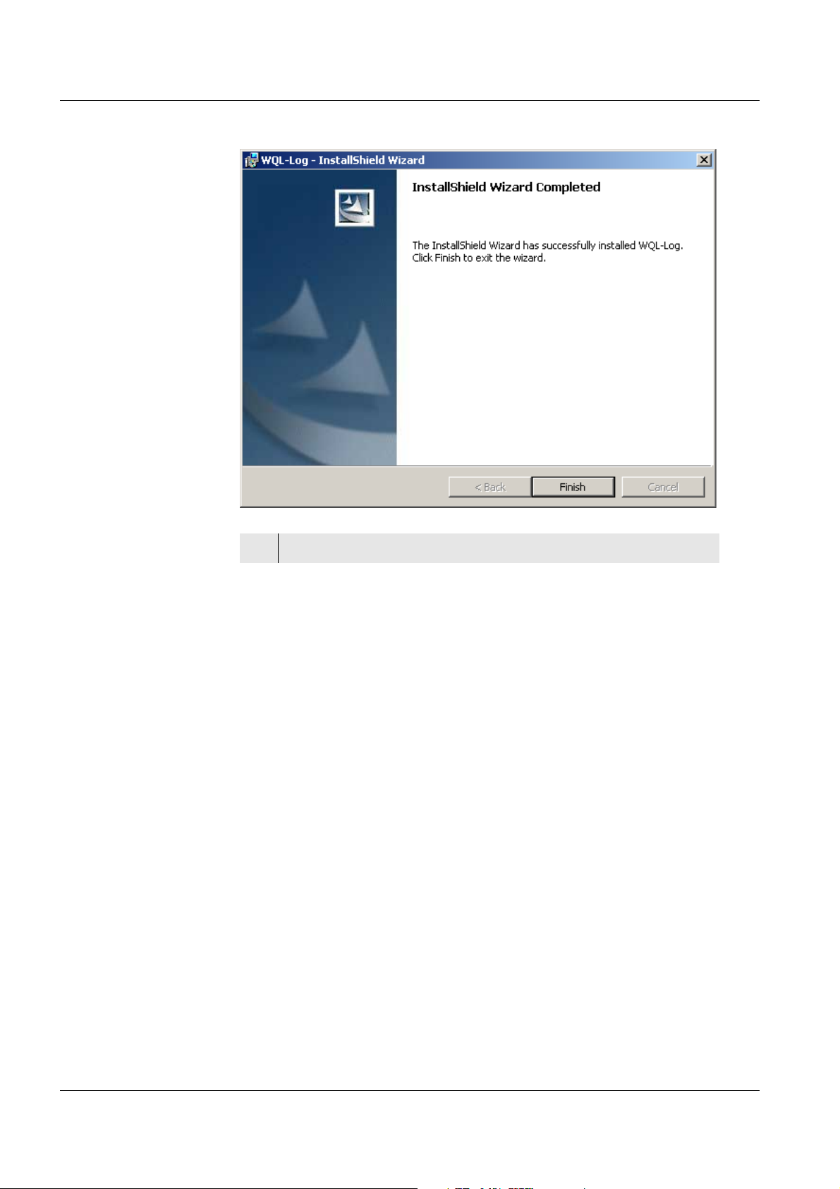
17 Click Finish to complete the installation.
114
ba75822e01 03/2011
Page 19
WQL-Cond Commissioning
3.4 Initial commissioning
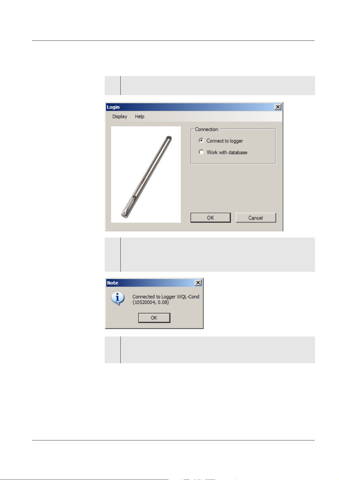
1 Start the WQL-Log program (the relevant icon is on the desktop).
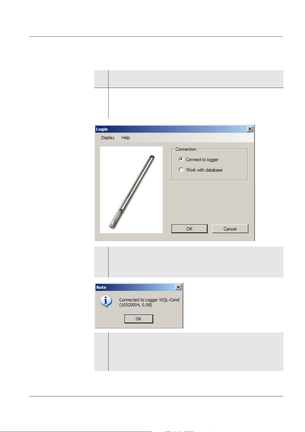
The Login window appears.
2 If the WQL-Cond logger is connected to the PC via a USB cable and
should communicate with the WQL-Log PC program:
Confirm with OK. The WQL-Log program searches for the connection
with the logger.
3 Confirm with OK.
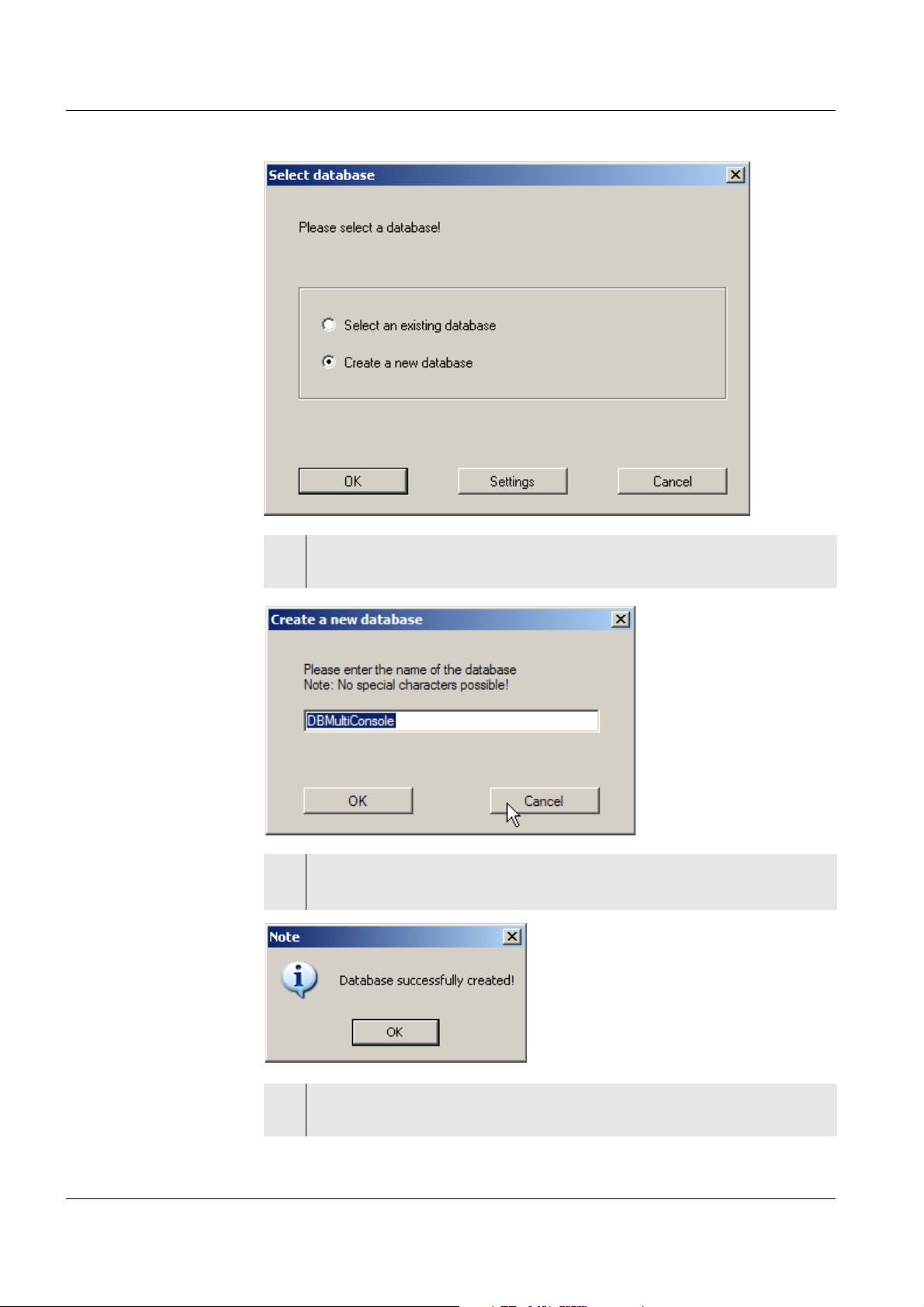
During the initial commissioning, the Select database window
appears.
ba75822e01 03/2011
115
Page 20
Commissioning WQL-Cond
4 Confirm the option, Create a new database with OK. The window to
save the newly created database appears.
5 Change the name of the database as necessary.
Click OK. The database is stored and a message appears:
116
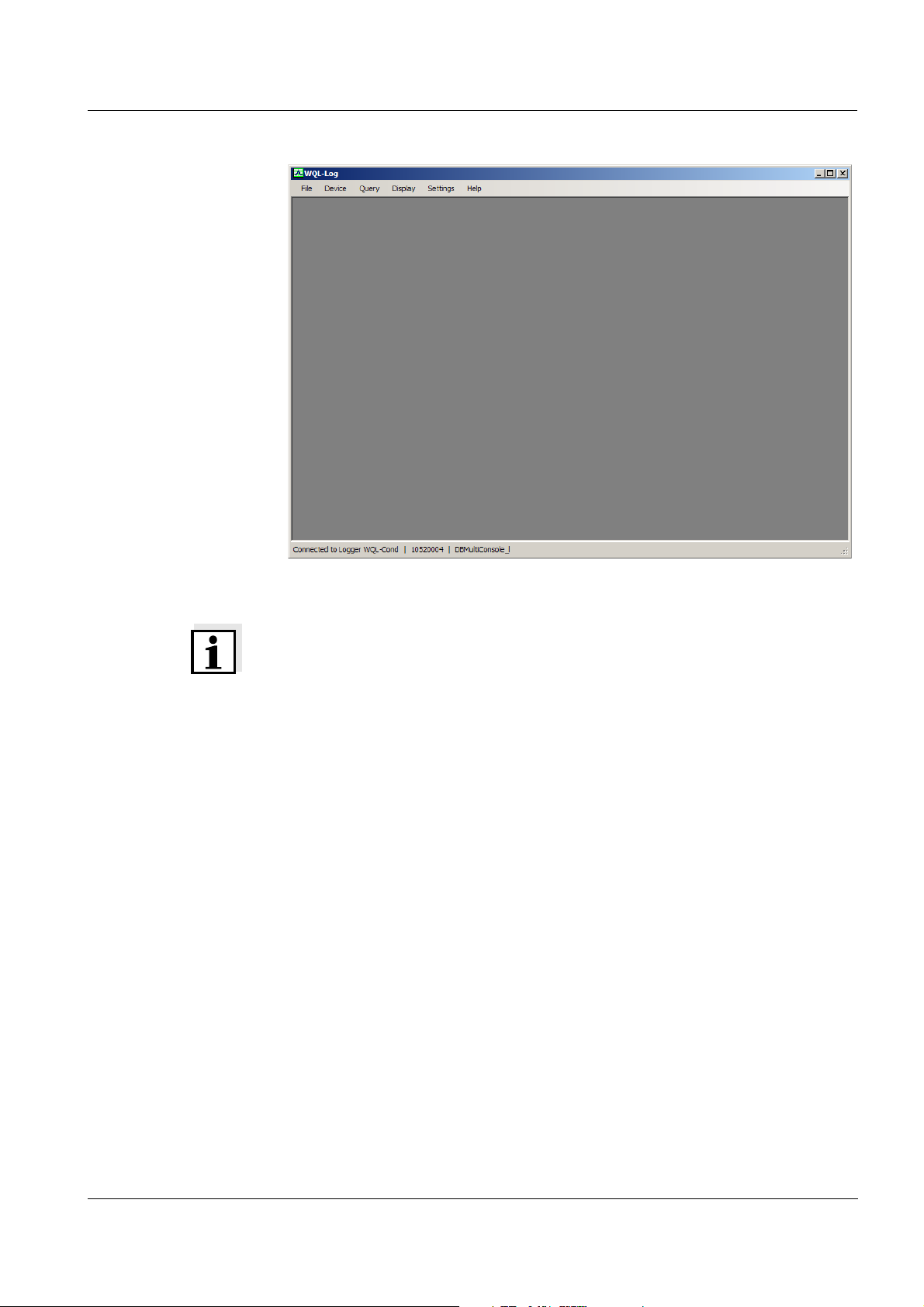
6 Confirm with OK. An empty data window appears, as the database is
still empty:
ba75822e01 03/2011
Page 21
WQL-Cond Commissioning
Note
If the SQL server was already installed for another application, you have to
change the password for the SQL server first before the WQL-Log program
can create a database. To change the password see section
13.3 C
OMMUNICATION BETWEEN PC PROGRAM AND SQL SERVER.
ba75822e01 03/2011
117
Page 22

Commissioning WQL-Cond
3.5 Connection types
The PC program WQL-Log works with two types of connection:
z Work with database
(the logger and PC program do not communicate)
z Connected to logger
(the logger and PC program communicate)
Working with the
database
Connected to the
logger
In this type of connection it is only possible to process the measurement data
stored in a database and to change the system settings.
When the logger is logged on and connected to the WQL-Log PC program,
the program and the logger communicate with each other. The measurement
datasets present in the logger can be imported to the database and are thus
available for processing.
You can configure the logger according to your requirements and set up a
logging job. When the logging job is started, the connection between the
logger and the WQL-Log PC program is cut. The cable connection between
the logger and PC does not have to be disconnected for this.
118
ba75822e01 03/2011
Page 23
WQL-Cond Commissioning
3.6 Starting the WQL-Log program
1 Start the WQL-Log program.
The Login window appears.
2 If necessary, you can change the display language here with the
menu item, Display (see section 4.1 S
out which software version of the WQL-Log program is installed with
the menu item, Help (see section 10.3 P
ETTING THE LANGUAGE) and find
ROGRAM INFO).
Connection to
logger
3 If the WQL-Cond logger is connected to the PC via a USB cable and
should communicate with the WQL-Log PC program:
Confirm with OK. The WQL-Log program searches for the connection
with the logger.
4 Confirm with OK. The data window appears.
If there are no data in the database (such as during the initial
commissioning), an empty data window appears.
If data are stored in the logger, an overview of the logging jobs
appears first (see section 8.8 M
ANAGING THE LOGGING JOBS).
ba75822e01 03/2011
119
Page 24
Commissioning WQL-Cond
Working with the
database
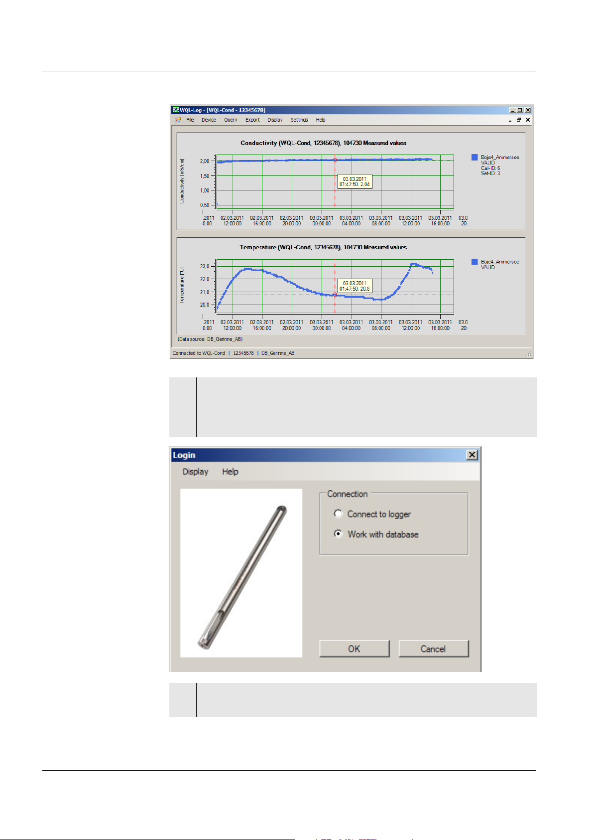
5 If you want to work with the database:
Select Work with database and confirm with OK.
The data window appears with the logger data that was last read in
(during the initial commissioning, an empty data window appears).
120
6 To continue, see chapter 9 WORKING WITH THE DATABASE AND
MEASUREMENT DATA.
ba75822e01 03/2011
Page 25
WQL-Cond Setting the display
4 Setting the display
Under the Display menu item you can set the language and temperature for
the WQL-Log PC program and the WQL-Cond logger. You can additionally
set whether or not a cursor with a value field with time, date and measured
value should appear for each measured parameter in the data window.
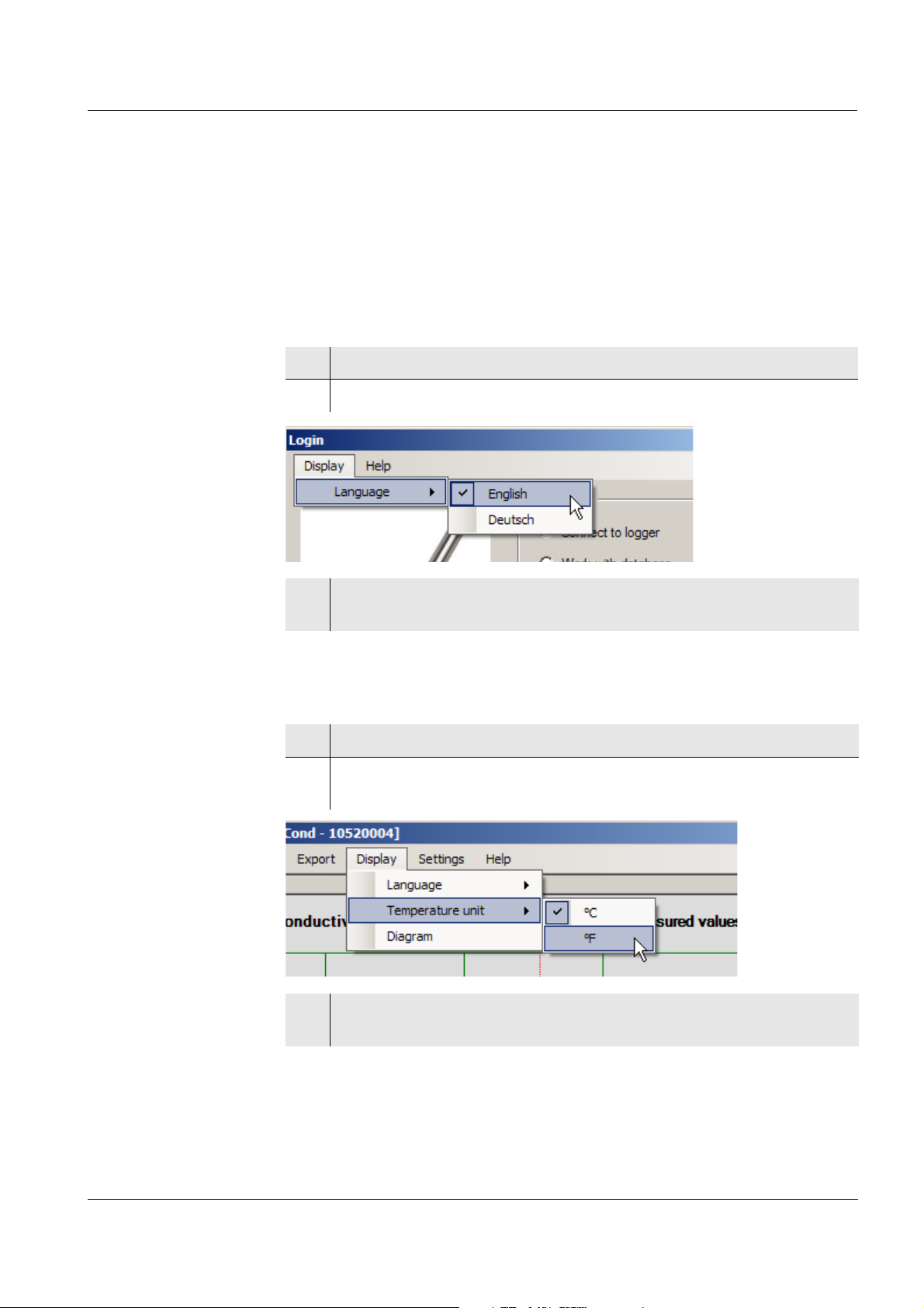
4.1 Setting the language
1 In the Display menu, select the menu item, Language.
2 The options Deutsch (German) and Englisch (English) appear.
3 Select the required language with a mouse click.
The setting is immediately active.
4.2 Setting the temperature unit
1 In the Display menu, select the menu item, Temperature unit.
2 The options, ° C (degrees Celsius) and ° F (degrees Fahrenheit)
appear.
3 Select the required temperature unit with a mouse click.
The setting is immediately active.
ba75822e01 03/2011
121
Page 26
Setting the display WQL-Cond
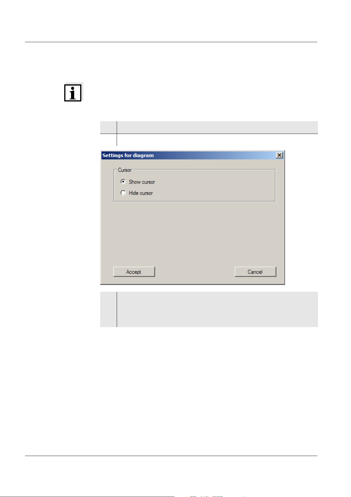
4.3 Setting the cursor
Note
The Diagram menu item appears only if data are available in the database.
1 In the Display menu, select the menu item, Diagram.
2 The options, Show cursor and Hide cursor appear.
122
3 Select the required option with a mouse click.
After clicking on Accept the setting is immediately active. The data
window appears with the cursor and value field. You can change the
position of the cursor by moving the data window with the mouse.
ba75822e01 03/2011
Page 27
WQL-Cond Setting the display
ba75822e01 03/2011
123
Page 28

Setting the measuring mode WQL-Cond
5 Setting the measuring mode
You can make the following settings in the Device / Set menu (default setting
in bold):
Measuring mode z Conductivity
[μS/cm] / [mS/cm]
z Salinity Sal [ ]
z TDS
[mg/l] / [g/l] with adjustable TDS factor
in the range 0.40 ... 1.00
z Resistivity
[Ω·cm] / [kΩ·cm] / [MΩ·cm]
Temperature compensation z Nonlinear temperature
compensation (nLF) according to EN
27 888
z Linear temperature compensation (lin)
with adjustable coefficients in the
range 0.000 ... 2.000 ... 3.000 %
/K
z No temperature compensation (off)
Reference temperature z 25 °C
z 20°C
TDS factor The factor to calculate the total dissolved solids is set to 1.00 in the factory.
You can adjust this factor to meet your requirements in the range of 0.40 to
1.00. The factor is set in the menu for the parameter, TDS.
Temperature
compensation
-Temperature
coefficient
The calculation of the temperature compensation is based on the preset
reference temperature, 20 °C or 25 °C. The reference temperature is shown
on the display.
The temperature coefficient for the linear temperature compensation is set to
2.000 %/K in the factory. You can adjust this factor to meet your requirements
in the range 0.000 ... 3.000 %/K. The factor is set in the menu for the setting
of the temperature compensation.
Note
More information on conductivity measurements is given in the WTW
conductivity primer.
124
ba75822e01 03/2011
Page 29
WQL-Cond Setting the measuring mode
Application tips Select the temperature compensations given in the table according to the
respective test sample:
Test sample Temperature compensation Display
Natural water
(ground water, surface
nLF
according to EN 27 888
nLF
water, drinking water,
waste water)
Other aqueous solutions Set linear
Linear
temperature coefficient
0.000 ... 3.000 %/K
Salinity (seawater) Automatic according to IOT
(International Oceanographic
Tables)
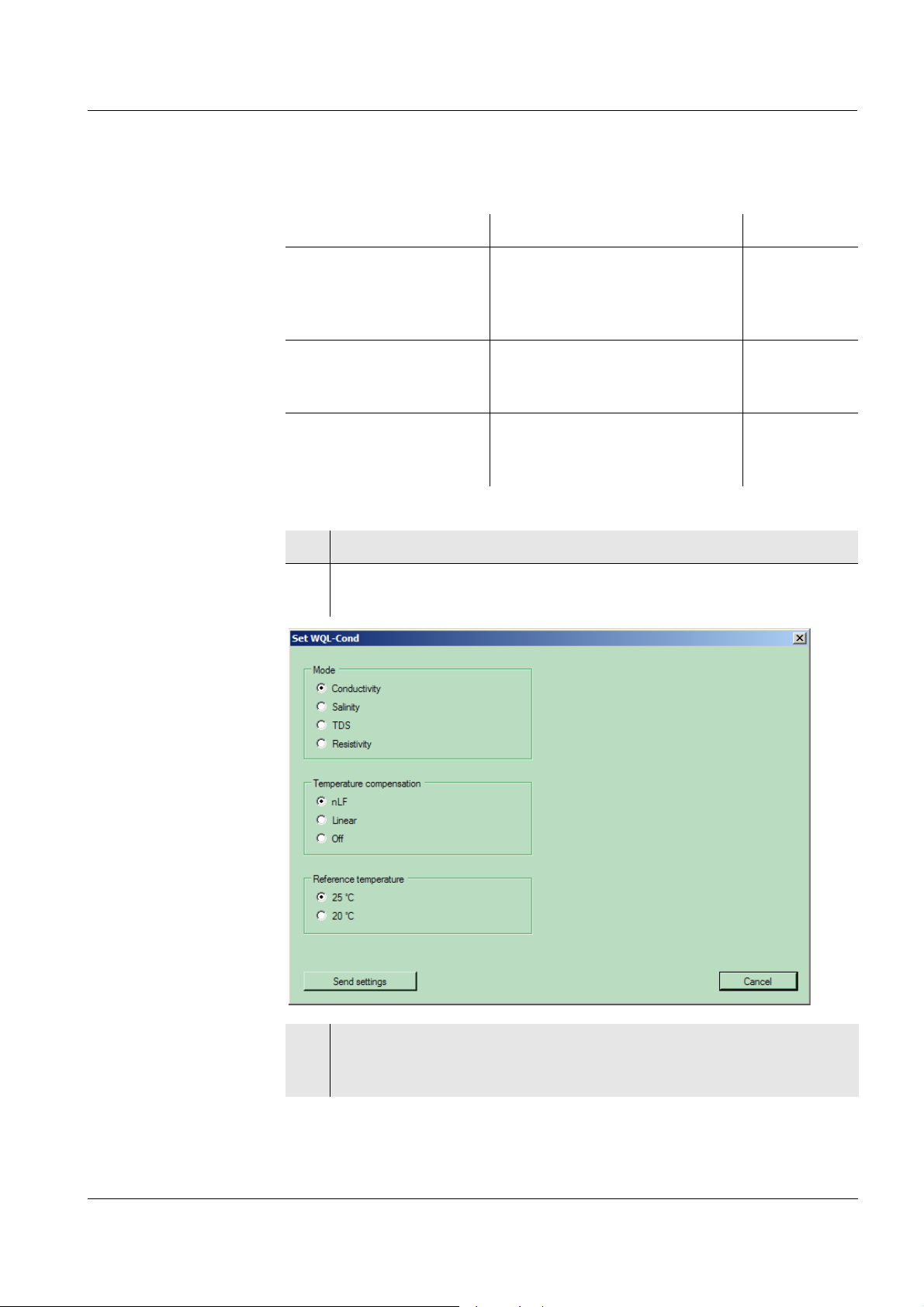
1 In the Device menu, select the menu item, Set.
2 The window for the selection of the measuring mode, temperature
compensation and reference temperature appears.
ba75822e01 03/2011
3 Select the required settings with a mouse click.
Clic Send settings.
A confirmation message appears:
125
Page 30
Setting the measuring mode WQL-Cond
4 Confirm with OK.
126
ba75822e01 03/2011
Page 31

WQL-Cond Calibration in control standard (determining the cell constant)
6 Calibration in control standard (determining
the cell constant)
Why determine the
cell constant?
Procedure You can determine the actual cell constant of the WQL-Cond logger by
Aging slightly changes the cell constant, e. g. due to coatings. As a result, an
inexact measured value is displayed. The original characteristics of the cell
can often be restored by cleaning the cell. Calibration determines the current
value of the cell constant and stores this value in the logger.
Thus, we recommend calibrating at regular intervals:
z on initial commissioning
z before starting a logging job.
calibrating with the control standard in the following range:
0.450 ... 0.500 cm
(nominal cell constant 0.475 cm
-1
-1
)
The cell constant is determined in the control standard,
0.01 mol/l KCl.
In the default condition, the calibrated cell constant of the WQL-Cond logger
-1
is set to 0.475 cm
.
AutoRead During calibration, the AutoRead function is automatically activated. The
AutoRead function checks the stability of the measurement signal and the
stability of the temperature signal. The stability has a considerable effect on
the reproducibility of the measured value.
The current AutoRead measurement can be terminated at any time
(accepting the current value).
ba75822e01 03/2011
127
Page 32

Calibration in control standard (determining the cell constant) WQL-Cond
6.1 Calibration settings
Calibration
procedures
Selecting the
calibration
procedure
Two calibration procedures can be selected:
z Manual (with a control standard of your choice)
z Automatic (with 0.01 mol/l KCl control standard)
1 In the Device menu, click the menu item, Calibrate.
2 The calibration window appears.
Here you can select the Manual or Automatic calibration procedure.
128
3 In the mode menu, highlight the required calibration procedure and
select it with a mouse click.
The selected setting is immediately active.
ba75822e01 03/2011
Page 33

WQL-Cond Calibration in control standard (determining the cell constant)
6.2 Calibrating (automatic)
Note
We recommend to always calibrate with the protective hood screwed on so
the measuring cell is protected. Use a stand as necessary.
Preparatory
activities
1 Connect the WQL-Cond logger to a USB port of your PC with the
USB cable.
2 Have the 0.01 mol/l KCl control standard ready.
3 In the Device menu, click the menu item, Calibrate.
The calibration window appears.
Calibration
4 Immerse the logger in the 0.01 mol/l KCl control standard.
5 Use the Next button to start the measurement.
ba75822e01 03/2011
129
Page 34

Calibration in control standard (determining the cell constant) WQL-Cond
Calibration record
6 The note, AutoRead is running... appears.
As soon as a stable value is recognized, the calibration record
appears.
Note
You can prematurely terminate the AutoRead function manually with Accept
at any time. If the AutoRead function is prematurely terminated, the current
measurement data are accepted immediately.
130
ba75822e01 03/2011
Page 35

WQL-Cond Calibration in control standard (determining the cell constant)
7 Accept the calibration with Accept. The message Calibration
successful appears and the new calibration will now be used for
measurement.
If you press Cancel, the logger discards the new calibration and will
continue to use the previous calibration values.
Note
The calibration history with the data of the last 20 calibration procedures can
be displayed at any time (see section 6.4 V
HISTORY).
IEWING THE CALIBRATION
ba75822e01 03/2011
131
Page 36

Calibration in control standard (determining the cell constant) WQL-Cond
6.3 Calibrating (manual)
Note
We recommend to always calibrate with the protective hood screwed on so
the measuring cell is protected. Use a stand as necessary.
Note
For manual calibration with a control standard, the temperature dependent
conductivity values of the standard are required. Normally a table with these
values is enclosed with the control standard.
z Prior to manual calibration, please switch off the temperature
compensation (menu, Device / Set).
z Determine the conductivity of the used standard solution using the
temperature measured by the logger during calibration (interpolate the
table values as necessary).
z After the calibration is completed, restore the required setting for the
temperature compensation.
Preparatory
activities
Calibration
1 Connect the WQL-Cond logger to a USB port of your PC with the
USB cable.
2 Keep a control standard of your choice ready.
3 In the Device menu, click the menu item, Calibrate.
The calibration window appears.
4 Immerse the logger in the control standard.
132
ba75822e01 03/2011
Page 37

WQL-Cond Calibration in control standard (determining the cell constant)
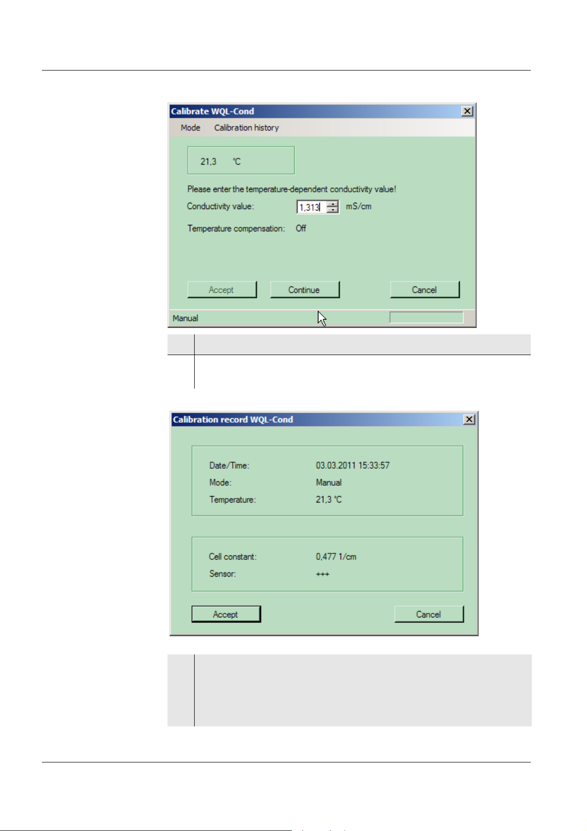
5 Use the Continue button to start the measurement.
ba75822e01 03/2011
6 The note, AutoRead is running... appears.
As soon as the value is stable, the prompt to enter the temperature
dependent conductivity value appears.
Note
You can prematurely terminate the AutoRead function manually with Accept
at any time. If the AutoRead function is prematurely terminated, the current
measurement data are accepted immediately.
133
Page 38
Calibration in control standard (determining the cell constant) WQL-Cond
7 Enter the conductivity value for the displayed temperature.
Calibration record
8Click Continue. As soon as a stable value is recognized, the
calibration record appears.
134
9 Accept the calibration with Accept. The message Calibration
successful appears and the new calibration will now be used for
measurement.
If you press Cancel, the logger discards the new calibration and will
continue to use the previous calibration values.
ba75822e01 03/2011
Page 39

WQL-Cond Calibration in control standard (determining the cell constant)
Note
The calibration history with the data of the last 20 calibration procedures can
be displayed at any time (see section 6.4 V
HISTORY).
IEWING THE CALIBRATION
Calibration
evaluation
After calibration, the system automatically evaluates the current status of the
calibration. The evaluation appears also in the calibration record.
Calibration record Cell constant [cm-1]
+++ Within the range
-1
-1
Error
0.450 ... 0.500 cm
Outside the range
0.450 ... 0.500 cm
Eliminate the error according to
chapter 13 W
HAT TO DO IF...
Note
The logger can store up to 20 logging jobs with the respective calibration
records and setting data. If, however, you calibrated several times for one
logging job and the logger would thus have to store more than 20 calibration
records with the 20th logging job, a message informs you of this.
This is to ensure that no calibration record for which there are measured
values can be lost. In this case the logger will prompt you to delete the
logger memory.
ba75822e01 03/2011
Make sure that you have read in all data you want to use before deleting the
logger memory. The logger memory can only be deleted completely.
135
Page 40

Calibration in control standard (determining the cell constant) WQL-Cond
6.4 Viewing the calibration history
The last 20 calibration records are stored in the logger and can be recalled.
Proceed as follows:
1 In the Device menu, select the Set menu item, and select the
measuring mode for which the calibration history should be
displayed.
2 In the Device menu, click the menu item, Calibrate.
3 The calibration window appears.
4 Click the menu item, Calibration history. The program reads the
calibration data of the set measuring mode.
136
5 The calibration history with the data of the last 20 calibration
procedures appears. Use the arrows on the side to scroll up or down.
ba75822e01 03/2011
Page 41

WQL-Cond Calibration in control standard (determining the cell constant)
6 Return to the calibration window with Cancel.
Note
Each calibration is given an individual calibration ID, which is stored with the
logged measured values together with the calibration date and time (see
section 9.8 E
XPORTING DATA).
ba75822e01 03/2011
137
Page 42

Calibration in control standard (determining the cell constant) WQL-Cond
6.5 Exporting the calibration history
The last 20 calibration records are stored in the logger as the calibration
history and can be exported as a csv file. Proceed as follows:
1 In the calibration history window, select the Export menu item.
2 Select the option, Export as *.csv file. The window to save the
calibration history appears.
138
3 Change the location and name of the file as necessary.
4 Confirm with the Save button.
5 A message appears, confirming that the file with the calibration
history was stored.
6 Confirm with OK.
ba75822e01 03/2011
Page 43

WQL-Cond Measuring directly
7 Measuring directly
The WQL-Log PC program in conjunction with the WQL-Cond logger can
measure and display the value of a solution directly according to the set
parameter. The directly measured values are not stored in the logger.
Proceed as follows when you want to measure directly:
1 Connect the WQL-Cond logger to the PC with the USB cable.
2 In the Device/Login menu, connect the logger to the WQL-Log PC
program.
3 If a logging job is running, terminate or interrupt it (measuring directly
is not possible while a logging job is running).
4 In the Device menu, click the Set menu item and select the settings
for the measuring mode and temperature compensation (see chapter
ETTING THE MEASURING MODE).
5S
5 In the Device menu, click the Measure directly menu item.
6 Immerse the WQL-Cond logger in the measuring solution.
7 The measured value window pops up with the measured value
(depending on the setting) and the temperature value of the test
sample.
Next to the measured value, the set temperature compensation and
if necessary, the temperature coefficient or TDS factor and reference
temperature are displayed.
ba75822e01 03/2011
8 Terminate the direct measurement with Quit.
139
Page 44

Logging WQL-Cond
8 Logging
Listed below are the typical operating steps with which to set up and carry out
a logging job. The chapters where the operating steps are described in detail
are also mentioned.
8.1 Typical sequence of a logging job (checklist)
1 Connect the logger to the PC with the USB cable.
2 Start the WQL-Log program (see section 3.6 S
PROGRAM).
TARTING THE WQL-LOG
3 Register the logger (see section 3.6 STARTING THE WQL-LOG
PROGRAM ).
4 If a logging job is running, terminate or interrupt it (see section
ANAGING THE LOGGING JOBS).
8.8 M
5 Erase the logger memory if necessary (see section 8.8 MANAGING THE
LOGGING JOBS).
6 Calibrate the logger (see chapter 6 C
STANDARD (DETERMINING THE CELL CONSTANT)
ALIBRATION IN CONTROL
7 Set up the logging job and send it (see section 8.3 SETTING THE
PARAMETERS AND STARTING THE LOGGING JOB).
8 Disconnect the USB cable from the logger.
9 If necessary, start the logger with the key button.
10 Check the operation of the logger based on the behavior of the signal
LED (see section 8.5 S
IGNAL LED AND LOGGER KEY BUTTON).
11 Tightly close the logger with the cap.
140
12 Install the logger at the measuring location.
13 After completion of the logging job: Connect the logger to the PC with
the USB cable (see step 1 etc.).
ba75822e01 03/2011
Page 45

WQL-Cond Logging
8.2 Setting up a logging job - setting parameters
You can set the following parameters for a logging job (i.e. the job to
determine and record measured values according to your requirements over
a certain period of time):
Tab Setting Setting options
(default setting in bold)
Recording Interval z User-defined (set the hours,
minutes, seconds)
z 1 second, 5 seconds,
10 seconds, 30 seconds
z 1 minute, 5 minutes, 10 minutes,
15 minutes, 30 minutes
z 1 hour, 2 hours, 3 hours,
6 hours, 9 hours, 12 hours,
24 hours
Start z Immediately (when the setting mode
is quit and the logger is separated
from the PC program)
z Logger key button
(when the key button at the control
panel of the logger is pressed)
z Delay
Set the time before the logger should
start logging: 1 hour ... 7 days
z Time
Set the date and time
Stop z Memory full (the loggers stops
logging only when the memory is full,
i.e. when 600,000 datasets have
been stored)
z Time period
(1 hour ... 365 days)
z Time
Set the date and time
Measured
value ID
You can assign a measured value ID
(consisting of up to 20 alphanumerical
character, no special characters) e.g.
the name of the measuring site).
Default setting: default
ba75822e01 03/2011
This tab provides you with information on the free memory capacity and
battery status.
141
Page 46

Logging WQL-Cond
Tab Setting Setting options
(default setting in bold)
Time Automatic time
adjustment
z Yes (date/time for the logger is
automatically synchronized with that
of the PC)
z No
(Enter the date/time for the logger)
Parameter Mode z Conductivity
[μS/cm] / [mS/cm]
z Salinity Sal [ ]
z TDS
[mg/l] / [g/l] with adjustable TDS
factor in the range 0.40 ... 1.00
z Resistivity
[Ω·cm] / [kΩ·cm] / [MΩ·cm]
Temperature
compensation
z Nonlinear temperature
compensation (nLF) according to
EN 27 888
z Linear temperature compensation
(lin) with adjustable coefficients in
the range 0.000 ... 2.000 ... 3.000 %/
K
z No temperature compensation (off)
Temperature
compensation
Reference
temperature
The calculation of the temperature compensation is based on the preset
reference temperature, 20 °C or 25 °C. The reference temperature is shown
z 25 °C
z 20°C
on the display.
Temperature
coefficient
The temperature coefficient for the linear temperature compensation is set to
2.000 %/K in the factory. You can adjust this factor to meet your requirements
in the range 0.000 ... 3.000 %/K. The factor is set in the menu for the setting
of the temperature compensation.
TDS factor The factor to calculate the total dissolved solids is set to 1.00 in the factory.
You can adjust this factor to meet your requirements in the range of 0.40 to
1.00. The factor is set in the menu for the parameter, TDS.
142
ba75822e01 03/2011
Page 47

WQL-Cond Logging
Application tips Select the temperature compensations given in the table according to the
respective test sample:
Test sample Temperature compensation Display
Natural water
(ground water, surface
nLF
according to EN 27 888
water, drinking water)
Other aqueous solutions Set linear
temperature coefficient
0.000 ... 3.000 %/K
Salinity (seawater) Automatic according to IOT
(International Oceanographic
Tables)
nLF
Linear
ba75822e01 03/2011
143
Page 48

Logging WQL-Cond
8.3 Setting the parameters and starting the logging job
To change one or several of the above listed settings proceed as follows:
1 Connect the WQL-Cond logger to the PC with the USB cable.
2 Start the WQL-Log program.
The Login window appears.
3 Confirm with OK. The WQL-Log program searches for the connection
with the logger.
4 Confirm with OK.
5 If the logger contains new data:
A window with the current logging jobs appears.
144
ba75822e01 03/2011
Page 49

WQL-Cond Logging
6 If a logging job is still running, click Stop.
7 To go to the data window without reading in any data, click Exit the
list.
If you wish to import the data, click Import.
The read-in process can take some time (depending on the number
of datasets to be read in).
ba75822e01 03/2011
145
Page 50

Logging WQL-Cond
Note
Do not unplug the cable connecting the logger to the PC during the read-in
process. If the connection is cut, the read-in process is terminated and has
to be repeated from scratch.
Note
Only click Delete all logging jobs if you want to discard all data stored in the
logger. This action will delete all jobs in the logger memory, and the data will
be irretrievably lost!
The jobs that were already imported and stored in the database are
retained.
8 When the import of the measured values is completed, a message
appears (confirm with OK) and the query to erase the complete
measured value memory.
9 Press OK or Cancel.
The data window appears with a graphic of the imported data, no
matter whether or not the data memory was erased.
146
ba75822e01 03/2011
Page 51

WQL-Cond Logging
10 In the Device menu, select the menu item, Set up logging job. A note
on calibration appears.
11 Confirm with OK. The Logging tab appears, the first tab of the
window, Set up logging job.
12 Based on the displayed percentages check whether the storage
capacity and battery charge are sufficient for the intended logging
job.
ba75822e01 03/2011
147
Page 52

Logging WQL-Cond
13 Interval: To set the logging interval, click the arrow on the right side
of the setting field. A drop-down menu appears with the possible
intervals. Select the required interval with a mouse click.
If User-defined was selected, click the arrows on the right side of the
selection fields and set the hours, minutes and seconds for the
interval.
14 Start: To set the start of the logging, click the arrow on the right side
of the setting field. A drop-down menu appears with the starting
times. Select the required starting time with a mouse click.
If Delay or Time was selected, click the arrows on the right side of the
selection fields and select the required period of time or set the point
in time.
15 Stop: To set the end of the logging, click the arrow on the right side
of the first setting field. A drop-down menu appears with the possible
settings. Select the required starting time with a mouse click.
If Time period or Time was selected, click the arrows on the right side
of the selection fields and select the required period of time or set the
point in time.
16 Measured value ID: Enter the measured value ID (up to 20
alphanumerical characters, no special characters).
148
17 Click the Time tab.
18 Select Yes or No for adjustment to PC time. If No was selected, click
the arrows on the right side of the selection fields and set the date
and time for the logger.
ba75822e01 03/2011
Page 53

WQL-Cond Logging
19 Click the Parameter tab.
20 Make the settings for the measuring mode and temperature
compensation and if necessary, for the reference temperature and
temperature compensation as well.
21 Save the settings for the logging job (configuration) as required (see
section 8.4 L
OGGING JOB - STORING OR LOADING THE CONFIGURATION).
Note
In the Logging tab, the memory capacity required with the selected settings
is displayed at the bottom (number x of 600,000 possible datasets).
ba75822e01 03/2011
149
Page 54

Logging WQL-Cond
Starting the
logging job
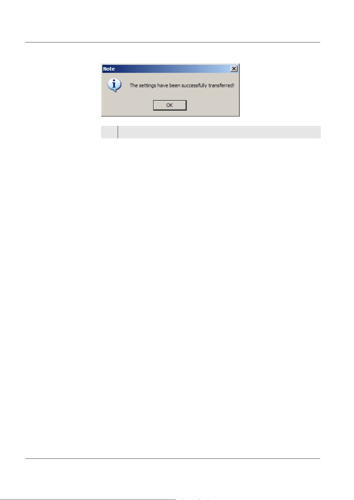
22 To start the logging job, click the button, Send logging job. The
message, The settings have been successfully transferred appears.
23 Confirm with OK. A window pops up with an overview of the logging
job just sent.
24 Confirm with OK. A note appears with the message that the logger
will now be disconnected from the PC program and, depending on the
setting, the information that the logging is started immediately or that
the logging is started when the logger key button is pressed.
25 Confirm with OK.
Note
The setting routine for the logging job can be canceled at any time with the
Cancel button. In this case the logger does not start the logging job; instead,
the data window appears after a note.
150
ba75822e01 03/2011
Page 55

WQL-Cond Logging
8.4 Logging job - storing or loading the configuration
You can store to a file the settings for a logging job and call them up later for
another logging job. To do so, proceed as follows:
1 In the File menu, select the submenu, Set up logging job.
2 After making the settings, click File in the Set up logging job window.
Storing the
configuration
3 To save the configuration of a logging job, click Save configuration.
The window to save the configuration appears.
ba75822e01 03/2011
151
Page 56

Logging WQL-Cond
Notes
z The program suggests a storage location and name for the file: the name
of the logger and the storing date and time (e.g. Logger WQLCond_Config_20110124_1619).
z The file has the file extension, ".xml".
z The suggested location and name can be changed.
4 Confirm with the Save button.
5 A message appears, confirming that the file with the configuration
was stored.
6 Confirm with OK.
Loading the
configuration
7 To load the configuration of a logging job, click Load configuration.
The Open window of the configuration appears.
152
8 Select the file and click Open.
9 A window with the stored configuration of the logging job appears.
Change the settings if necessary and set up the logging job as usual.
ba75822e01 03/2011
Page 57

WQL-Cond Logging
8.5 Signal LED and logger key button
8.5.1 Signal LED to indicate the operating conditions of the logger
Next to the key button on the control panel of the logger there is a signal LED.
When the logger is not connected to the WQL-Log PC program, this red LED
indicates the different operating conditions of the logger as follows:
Mode of flashing Operating condition
On for 2 seconds, then off z The logging job is completed.
z The power supply of the logger
was interrupted. The logger has to
be connected to the PC program in
order to set the date and time.
A short flashing every 2 seconds The logger is ready to log and can be
started with the logger key button.
A short flashing every 0.5 seconds The logging job is running (the logger
is logging).
Notes
z The flashing stops after 15 seconds to save energy. Short pressing of the
logger key button starts the flashing for 15 seconds again.
z Important: The logger can be started with the logger key button only while
the signal LED is flashing (if starting the logger with the key button was
set during the setting up of the logging job).
8.5.2 Logger key button
Next to the signal LED on the control panel of the logger there is a key button.
It has the following functions:
z With the corresponding setting, a logging job can be started by pressing
the key button. The pressure must last for at least 3 seconds, and the LED
lights up when the 3 seconds have passed.
z A running logging job can be stopped by pressing the key button for at
least 3 seconds. If you press the key button again for at least 3 seconds,
a new logging job with the same settings will be started (e.g for logging at
different locations).
z Pressing the key shortly activates the LED that indicates the operating
state of the logger for 15 seconds (see section 8.5.1 S
INDICATE THE OPERATING CONDITIONS OF THE LOGGER).
IGNAL LED TO
ba75822e01 03/2011
153
Page 58

Logging WQL-Cond
8.6 Importing data
Depending on the logging job, the WQL-Cond logger measures for a certain
period of time and at certain intervals the conductivity and temperature of a
solution. The data is stored in the logger. The WQL-Log PC program has to
import and store to a database the data before the data can be displayed and
processed.
Note
If the logger contains data, the list with the query for the use of the data
appears automatically when the logger is connected to the PC program.
To import the data of a logging job, proceed as follows:
1 Connect the WQL-Cond logger to the PC with the USB cable.
2 The list of logging jobs with their respective status appears.
154
3 If you wish to import the data of the highlighted job, click Import.
Further information, see section 8.8 M
ANAGING THE LOGGING JOBS.
Note
Only click Delete all logging jobs if you want to discard all data stored in the
logger. This action will delete all jobs in the logger memory, and the data will
be irretrievably lost!
The jobs that were already imported and stored in the database are
retained.
ba75822e01 03/2011
Page 59

WQL-Cond Logging
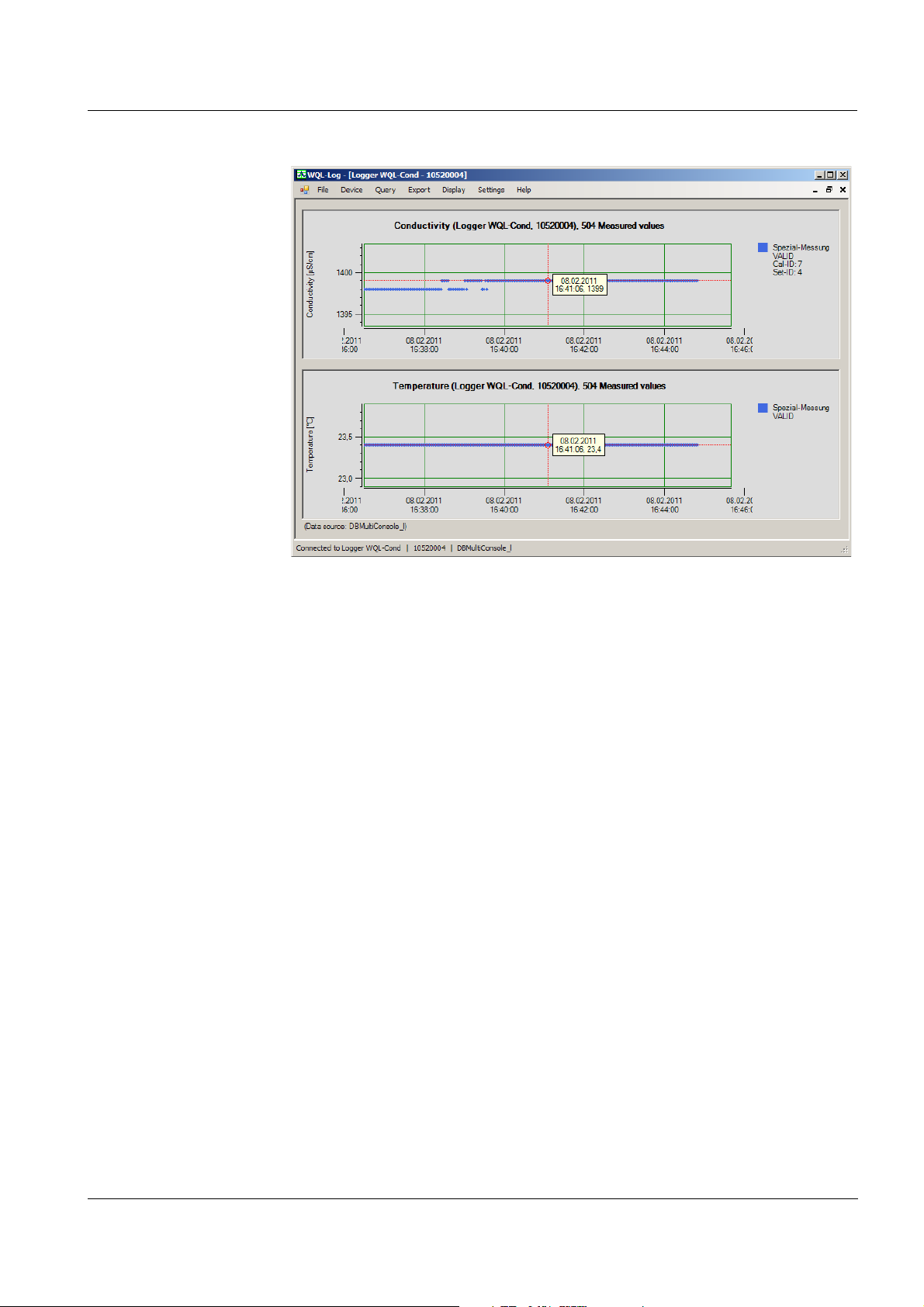
Cursor
Name and series
number of the
connected logger
Menu bar
Measured value ID,
status, Cal ID and
Set ID of the
displayed data.
Name and series
number of the logger
that provided the data
Name of the currently
connected (=open) database
Name of the database
providing the pictured
data
Number of
selected
datasets
Value
window (for
cursor
position)
8.7 Overview of the data window
The measurement datasets imported from the logger are stored in a
database and graphically displayed in a data window.
The data window is structured as follows:
ba75822e01 03/2011
155
Page 60

Logging WQL-Cond
8.8 Managing the logging jobs
The WQL-Cond logger can store up to 20 logging jobs with the respective
calibration data and setting data. You can view an overview of the logging
jobs stored in the logger, read them in individually, display each logging job
as a graphic or clear the logger memory.
Possible status
displays of a
logging job
Status display Explanation Options
Running.... The logger is logging. Stop logging job or
Cancel
Waiting... – The logger is waiting to
be started with the key
button
– The logger was
Start the logging job with
the logger key button,
Stop logging job or
Cancel
stopped with the key
button
– The waiting time/delay
of the start option Time
or Delay has not yet
expired.
Finished The logging job is finished
or was stopped. The data
Exit the list, Import or
Cancel
were not yet imported to the
database.
Imported The logging job is finished
Diagram view or Cancel
and the data were imported
to the database.
156
Viewing the
logging jobs
Note
After being imported, the logging jobs shown in the overview can be
individually shown as a graphic, but they can only be deleted completely.
Proceed as follows to view the list of logging jobs stored in the logger:
1 Connect the WQL-Cond logger to the PC with the USB cable.
2 In the Device menu, click the menu item, Manage logging jobs.
If a logging job is presently running, the following display with
information on the running job appears:
ba75822e01 03/2011
Page 61

WQL-Cond Logging
3 To stop the running job, click Stop logging job. The list of logging jobs
is displayed.
With Cancel the logging job goes on running and the logger is logged
off.
ba75822e01 03/2011
157
Page 62

Logging WQL-Cond
Showing a logging
job as a diagram
Clearing the
logger memory
4 Select a logging job with the arrow keys or with the mouse.
5 If the status is Finished, import the data of the highlighted logging job
to the database with Import (the diagram view is only available after
the data have been imported).
6 To show the data of the highlighted and imported logging job as a
graphic, click Diagram view.
7 If a logging job is selected that is finished but was not imported, the
Exit the list button appears. Use this button to go to the empty data
window.
8 To show the next logging job, select the menu item Manage logging
jobs in the Device menu.
Show the next job of the list of logging jobs as a diagram.
9Use Cancel to return to the data window with the last displayed
diagram view.
1 In the list of logging jobs, click the Delete all logging jobs button. A
security prompt appears:
158
Note
Only click Delete all logging jobs if you want to discard all data stored in the
logger. This action will delete all jobs in the logger memory, and the data will
be irretrievably lost!
The jobs that were already imported and stored in the database are
retained.
2 To delete all logging jobs, click the Yes button.
3 The data is cleared. A message appears after the clearing that
informs you that the memory was cleared. Confirm the message with
OK.
If No is selected, the program returns to the list of logging jobs.
ba75822e01 03/2011
Page 63

WQL-Cond Working with the database and measurement data
9 Working with the database and
measurement data
9.1 General information on the database
The WQL-Cond logger can generate large amounts of measurement data,
which can subsequently be stored, managed and used for evaluation with the
WQL-Log program. The WQL-Log program uses the Microsoft SQL Server
2005 Express database for this. All generated measurement data are
provided with additional information (such as measurement ID, sensor) and
stored in the currently connected database.
Database storage considerably differs from the file-based storage known
from one's daily PC work with word processing or spreadsheet programs. A
database is created and managed by a program, in our case WQL-Log. The
WQL-Log program creates several files and works with them.
Warning
z Always use the WQL-Log program to make any changes on the
database (such as creating, erasing, saving, restoring a database).
z Never erase any files created by the WQL-Log program with another
program (e.g. with MS Windows Explorer). In this case, WQL-Log might
not be able to access the database and the stored data are lost.
With a database you can use queries to select/filter certain events from the
stored measured values. You can e.g., search for measured values from
certain periods or individual locations. This enables the secure and userfriendly handling of large amounts of data.
ba75822e01 03/2011
159
Page 64

Working with the database and measurement data WQL-Cond
9.2 Creating a database
If no database is available on initial commissioning, its creation is enforced,
i.e. a database must first be created prior to storing data in it. If a database
already exists, newly generated data can be stored in it or you can create a
new database and store the data there.
Proceed as follows:
1 In the File menu, select the submenu, Create new database.
2 Confirm with OK.
3 A message appears informing you that the database was created.
4 Confirm with OK. The new database was created and is connected
with the WQL-Log program.
160
ba75822e01 03/2011
Page 65

WQL-Cond Working with the database and measurement data
9.3 Opening a database
When being started, the WQL-Log program automatically opens the
database last used. If there are several databases, you can select another
database to be opened.
Proceed as follows:
1 In the File menu, select the submenu, Open database. A window to
select the database pops up.
2 Click the arrow next to the Database name field and select the
required database.
3 Confirm with OK. The selected database is opened.
ba75822e01 03/2011
161
Page 66

Working with the database and measurement data WQL-Cond
9.4 Backing up a database
You can create a backup copy of an open database at any time.
Proceed as follows:
1 In the File menu, select the submenu, Back up database.
162
Notes
z The program suggests a storage location and name for the backup copy:
the name of the original database with the addition "backup" and the date
and time the backup copy is created.
z The backup copy has the file extension, ".bak".
z The suggested location and name can be changed.
2 Change the location and name of the backup copy as necessary.
3 Confirm with the Save button.
4 A message appears informing you that the database was saved.
5 Confirm with OK. The backup copy of the database has been
created.
ba75822e01 03/2011
Page 67

WQL-Cond Working with the database and measurement data
9.5 Restoring a database
You can restore a database from a backup copy (see section 9.4 BACKING UP
A DATABASE) at any time by opening the backup copy from a connected
database. This can either be an existing database you want to restore to a
previous state or a newly created, empty database into which you want to
store the saved data in case the original database was destroyed or
inadvertently erased.
Warning
z The database from where you open the copy to be restored is
overwritten with the backup copy to be restored. Data that were stored
in the database will be irrevocably lost on restoring the backup copy!
z If you are in any doubt, open a backup copy to be restored from an
empty, newly created database (see section 9.2 C
Proceed as follows:
REATING A DATABASE).
1 In the File menu, select the submenu, Open database.
2 Select the database into which you want to import the database to be
restored.
3 In the File menu, select the submenu, Restore database.
4 Select the location and name of the backup copy (*.bak) to be
restored.
ba75822e01 03/2011
163
Page 68

Working with the database and measurement data WQL-Cond
5 Confirm with the Open button.
A security prompt appears:
6 Click the option Yes and confirm with OK.
A message appears:
164
7 Confirm with OK.
The database has been restored.
ba75822e01 03/2011
Page 69

WQL-Cond Working with the database and measurement data
9.6 Erasing a database
You can erase any connected database of the WQL-Log program.
Proceed as follows:
1 Make sure that the database you want to erase is connected (=
open), or open the database with the menu, File / Open database.
2 Open the menu, File / Delete database. A security prompt appears:
3 Click the option Yes and confirm with OK. The database is erased. If
it was the only database, a window to create a new database pops
up.
ba75822e01 03/2011
165
Page 70

Working with the database and measurement data WQL-Cond
9.7 Querying data
The data recorded by the logger and stored in the database can be displayed
as a graphic via the Query menu item. Proceed as follows:
Querying current
data
1 In the Query menu, click the menu item, New.
The New query window appears.
2 The Standard tab appears when a logger is connected.
3 To graphically display the data last imported from the connected
logger, click Apply. The data appear as a graphic, broken according
to conductivity value and temperature.
166
ba75822e01 03/2011
Page 71

WQL-Cond Working with the database and measurement data
Note
You can change the position of the cursor by moving the data window with
the mouse.
Note
The series number of the connected logger is displayed in the bottom left
corner of the data window (see section 8.7 O
VERVIEW OF THE DATA WINDOW).
ba75822e01 03/2011
167
Page 72

Working with the database and measurement data WQL-Cond
Querying user-
defined data
1 Click the User-defined tab in the New query window. The User-
defined tab appears immediately in the Query menu if no logger is
connected.
2 If you only want to query datasets with a certain measured value ID,
check off the box for Measured value ID and then click the arrow next
to the selection field for the Measured value ID. Select the required
measured value ID.
3 In the Sensors field, select one or two measured values to be
queried.
4 If you only want to query datasets with a certain date, check off the
box for Time period and then click the arrow next to the selection
fields for the time (from and to). Select the required date in both fields.
Next to the date fields are the time fields where you enter the time
(hours, minutes, seconds) either with the arrow keys or by entering
the number with the keyboard.
5Click Apply to display the selected datasets.
168
ba75822e01 03/2011
Page 73

WQL-Cond Working with the database and measurement data
6 The queried data appear as a graphic.
Note
Always make the settings for the user-defined query from the top down, as
the data are filtered in this sequence.
Note
If you do several queries, even from several databases, an additional
window with a graphic appears for each query. You can cascade these
windows with the Restore down ( ) button. You can also arrange the
windows side by side in order to compare several graphics.
ba75822e01 03/2011
169
Page 74

Working with the database and measurement data WQL-Cond
9.8 Exporting data
The data displayed as a graphic with the aid of the Query menu can be
exported to a *.csv file. The WQL-Log program creates three csv files with
each export procedure: One with the measurement data, one with the
calibration data and a third one with the setting data.
In this form the data can be read and processed with Microsoft Excel and
many other spreadsheets.
Note
If the number of datasets to be exported is more than 60,000 and the data
are to be processed with Microsoft Excel 2007 or older, export the data with
the function, "Export as *.csv file (splitted)", as Excel versions 2007 and
older can store only 60,000 datasets in one worksheet. The number of
datasets is given in the header of the graphic, next to the series number of
the logger that provided the data.
Proceed as follows to export the datasets displayed as a graphic:
1 In the Export menu, click the menu item, Export as *.csv file or Export
as *.csv file (splitted).
The Save as window appears.
170
2 The WQL-Log PC program suggests a directory and file name. Store
the data to be exported in the selected directory under the required
name with the Save button.
3 A note on the successful data export appears. Confirm with OK.
ba75822e01 03/2011
Page 75

WQL-Cond Working with the database and measurement data
Notes
The WQL-Log program creates three csv files with each export procedure:
z A csv file with the measurement data and information on the logger and
logging job (suggested name with date and time)
z A csv file with the relevant setting data (suggested name with date and
time and the addition, "Set")
z A csv file with the relevant calibration data (suggested name with date
and time and the addition, "Cal")
z If the number of datasets to be exported is more than 60,000 and the data
is exported with the function, Export as *.csv file (splitted), the WQL-Log
program automatically divides the data into files with max. 60,000
datasets and adds a 1, 2 etc. to the suggested file names.
ba75822e01 03/2011
171
Page 76

Working with the database and measurement data WQL-Cond
Example: Exported
measurement data
opened with MS
Excel
The csv file with the measurement data includes the following information:
z Sensor name
z Series number of the logger (SerNo)
z Start and stop (time) of the exported data
z Date and time of the measured values
AutoRange
function
z Measured value
z Measured value status (Valid; Invalid; OFL/UFL = outside the measuring
range; Ranging = optimal measuring range is being searched)
z Temperature
z Measured value status (Valid; Invalid; OFL/UFL = outside the measuring
range)
z Measured value ID (MeasID)
z Calibration ID (CalProtID) so you can allocate the calibration data if there
are several calibration procedures for the exported data - see csv file with
calibration data).
z Date and time of the calibration (CalDateTime)
z Settings ID (SetID) so you can allocate the settings for the exported data
- see csv file with setting data).
Due to the large scope of conductivity measurements ( 1 ... 1.000.000 μS/cm)
the WQL-Cond logger automatically searches for the suitable measuring
range. In the most unfavorable case (changing from the largest to the
smallest measuring range or vice versa) it takes the logger a response time
of approx. 8 seconds to do this.
172
In the case of extreme conductivity jumps, the logger can determine the real
conductivity value only approximately because of this response time.
Approximate values are indicated with the measured value status,
RANGING.
When measuring directly, the conductivity value is only displayed after the
suitable measuring range has been found.
ba75822e01 03/2011
Page 77

WQL-Cond Working with the database and measurement data
Example: Exported
calibration data
opened with MS
Excel
The csv file with the calibration data includes the following information:
z Sensor name
z Series number of the logger (SerNo)
z Calibration ID, so you can allocate the calibration data if there are several
calibration procedures for the exported data
z Date and time of the calibration
z Calibration mode (Mode)
z Calibration temperature (Temp)
Example: Exported
setting data
opened with MS
Excel
z Cell constant (CellConst)
z Calibration evaluation
(CalStatus - similar to C
ALIBRATION EVALUATION, page 135)
The csv file with the setting data includes the following information:
z Sensor name
z Series number of the logger (SerNo)
z Settings ID (ID) so you can allocate the settings for the exported data
z Temperature compensation (TempComp)
z Reference temperature (TRef [°C])
z Temperature coefficient (LinCoeff [%/K])
ba75822e01 03/2011
z TDS factor
173
Page 78

Info menus WQL-Cond
10 Info menus
10.1 Database information
The data read in from the logger are saved in a database. You can query the
name, version and type of the opened database.
To do so, proceed as follows:
Database
information
1 In the File menu, click the menu item, Database info.
The Database info window appears.
2 Confirm with OK. The Database info window disappears.
Note
The size of a database file can be 4 GB max. When this amount of data is
stored, a new database file must be created. The new database file is
created in the Device/Create new database menu.
A database with 50,000 datasets requires approx. 7 MB storage space. Thus
the database can store approx. 12,5 million datasets.
174
ba75822e01 03/2011
Page 79

WQL-Cond Info menus
10.2 Device information
If a logger is connected to the PC, you can query the device name, series
number and firmware version of the connected logger via the Device/Info
menu item.
To do so, proceed as follows:
Device information
1 In the Device menu, click the menu item, Info.
The Device info window appears.
2 Confirm with OK. The Device info window disappears.
ba75822e01 03/2011
175
Page 80

Info menus WQL-Cond
10.3 Program info
In the Help/About WQL-Log menu you can look up which version of the WQLLog PC program was installed.
To do so, proceed as follows:
1 In the Help menu, click the About WQL-Log menu item.
The About WQL-Log
Program info
window appears.
2 Confirm with OK. The About WQL-Log window disappears.
176
ba75822e01 03/2011
Page 81

WQL-Cond Resetting the logger
11 Resetting the logger
You can reset to the default condition the logger and the PC program with its
settings.
In the default condition, the settings are as follows:
Configuration parameters Setting
Logging interval 1 second
Start of the logging Logger key button
End of the logging Time period
1 hour
Measured value ID default
Measuring mode Conductivity
Temperature compensation nLF
Resetting to
default condition
Temperature coefficient 2.000
Reference temperature 25 °C
Cell constant 0.475 cm
-1
TDS factor 1.00
Date, time 01.01.2003, 00:00
Calibration records None
Notes
z The Device / Reset function deletes the calibration records as well as all
measurement data from the logger! Before deleting the logger memory,
make sure that you have imported to the database all data you want to
keep.
z The battery counter is not reset with the Device / Reset function. It has to
be reset with the reset function of the battery manager.
To reset the logger and PC program to the default condition, proceed as
follows:
ba75822e01 03/2011
1 In the Device menu, click the menu item, Reset. A security prompt
appears.
2 Confirm with OK. The settings are reset to the default condition.
177
Page 82

Resetting the logger WQL-Cond
178
ba75822e01 03/2011
Page 83

WQL-Cond Maintenance, cleaning, storage
12 Maintenance, cleaning, storage
12.1 General maintenance instructions
General
information
Cleaning the
measuring cell
z Normally, all screw joints of the logger housing can be opened and closed
by hand, without using any tools. If necessary, use a paper towel so you
can get a better grip on the parts.
z In the screwed condition, no gaps may be visible at the joints.
z Prior to unscrewing any screw joints, clean the exterior of the logger (see
section 12.2 E
XTERIOR CLEANING) and dry it thoroughly.
z Prior to reassembly, clean all internal and external threads thoroughly.
Contaminated threads can get stuck by-and-by. Normally, the threads can
be screwed together without using any effort and without noticeable
grinding (sand particles).
z Clean all O-rings prior to reassembly. Dirt, e.g. fibers, on the O-rings can
affect the tightness. If the O-rings are damaged, they have to be
exchanged (see section 12.5 R
EPLACEMENT PARTS).
12.2 Exterior cleaning
Clean the logger with tapwater and a soft sponge or brush. Remove the
protective hood when you want to clean the measuring cell.
We recommend to clean the measuring cell thoroughly, especially before
measuring low conductivity values.
Aging of the
conductivity
measuring cell
Contamination Cleaning procedure
Lime sediments Immerse in acetic acid for 5 minutes (volume
share = 10 %)
Fat/oil Clean with warm water that contains
washing-up liquid
After cleaning, thoroughly rinse with deionized water and recalibrate if
necessary.
Normally, the conductivity measuring cell does not age. Special measuring
media (e.g. strong acids and bases, organic solvents) or temperatures that
are too high may considerably reduce its lifetime or lead to damage. The
warranty does not cover failure caused by measuring conditions and
mechanical damage.
ba75822e01 03/2011
179
Page 84

Maintenance, cleaning, storage WQL-Cond
12.3 Battery
12.3.1 Battery service life
The logger has an energy saving feature. The service life of the battery
depends very much on the usage of the logger, especially on the measuring
interval. The service life to be expected of a full battery (2600 mAh) can be
estimated by means of the following table:
Measuring interval Service time to be expected
1 ... 4 sec 1 months
5 ... 9 sec 1.5 months
10 .... 29 sec 2 months
30 ... 59 sec 5 months
1 min ... < 2 min 6 months
2 min ... < 5 min 11 months
5 min and longer 12 months
Note
The power consumption also depends on the measured value: When
measuring high conductivity values, the logger uses more energy, when
measuring low conductivity values, it uses less energy. The service times to
be expected given in the above table apply to a permanent conductivity of 10
mS/cm. With other conductivity values the service times will change
accordingly.
12.3.2 Ascertaining the battery status
The battery manager of the logger records the battery use so that you can
ascertain the battery status at any time. For this the battery counter has to be
reset when a new battery is inserted.
Note
Leave the battery installed even if you will store the logger for a longer period
of time. This ensures that the battery counter can properly work and display
the battery status.
Ascertaining the
battery status
180
1 In the Device menu, select the menu item, Battery manager.
The Battery manager window appears. The battery status is
displayed as a percentage (spent and free).
ba75822e01 03/2011
Page 85

WQL-Cond Maintenance, cleaning, storage
Resetting the
battery counter
Note
The battery status is also displayed while you are setting up a logging job
(see section 8.3 S
ETTING THE PARAMETERS AND STARTING THE LOGGING JOB).
12.3.3 Resetting the battery counter
For the battery status to be displayed correctly, the battery counter must be
reset on installing a new battery.
Proceed as follows:
1 In the Device menu, select the menu item, Battery manager.
The Battery manager window appears. Select the Reset button.
1 A security prompt appears. Confirm the reset with OK.
ba75822e01 03/2011
181
Page 86

Maintenance, cleaning, storage WQL-Cond
12.3.4 Battery replacement
Note
Always install a brand-new battery (see section 12.5 R
EPLACEMENT PARTS) so
the battery manager can work correctly. When replacing the battery the
general maintenance instructions in section 12.1 must also be followed.
The battery is replaced in the same way as it is inserted during the
commissioning (see section 3.1 I
NSERTING THE BATTERY).
Data preservation After the battery was removed all stored measured values are retained. Only
the date and time are reset to the default condition (01.01.2003, 00:00) when
the power supply is interrupted.
We recommend to connect the logger to the PC for the time of the battery
replacing so the logger is supplied with power while there is no battery
inserted. Thus the date and time will be retained. Otherwise, the date and
time will be set the next time the logger is connected to the PC with the WQLLog PC program. Depending on the setting in the WQL-Log program, this is
either done automatically when the connection is established
(synchronization with the system time of the PC), or manually.
Case 1: Logging
job active at the
time of
interruption
Case 2: No logging
job at the time of
interruption
State of the logger after the power supply was interrupted (battery empty or
removed, see also section 8.4 L
CONFIGURATION):
OGGING JOB - STORING OR LOADING THE
z The logging job is terminated.
z The time is reset to default.
z All data logged up to this point of time are retained and can be saved on
the PC the next time the logger is connected to the PC (see section
8.6 I
MPORTING DATA).
z The terminated logging job can be continued with a corresponding new
logging job as necessary. To do so, the time must be set anew if the
automatic time synchronization is switched off.
z The time is reset to default.
z Prior to setting up the next logging job, you have to set the time if the
automatic time synchronization is switched off.
182
ba75822e01 03/2011
Page 87

WQL-Cond Maintenance, cleaning, storage
12.4 Storage
Store the logger in a dry place, observing the storing conditions according to
section 14.2 A
PPLICATION CHARACTERISTICS. Low temperatures usually delay
the aging of the measuring cell.
Leave the battery installed for storage.
12.5 Replacement parts
Description Model Order
no.
3.6 V Li battery WQL-RB 109 825
Note
If the O-rings or shackle have to be replaced, please contact the WTW
service department.
ba75822e01 03/2011
183
Page 88

Maintenance, cleaning, storage WQL-Cond
184
ba75822e01 03/2011
Page 89

WQL-Cond What to do if...
13 What to do if...
13.1 Calibration and measuring
Unstable
measured values
Implausible
measured values
Incorrect
temperature
display
Cause Remedy
– No stable measured value – Provide stable measuring
conditions (e.g. temperature)
– Use a shorter USB cable
– USB-Hub or USB connection
– Use other USB connection or PC
at the PC faulty or defective
Cause Remedy
– Measuring range exceeded – Make sure the logger is suitable
for the application
– Contamination in the area of
the electrodes
– Clean the conductivity measuring
cell (see section 12.2 E
CLEANING).
XTERIOR
– Electrodes damaged – Return the logger
Cause Remedy
– The temperature sensor is not
immersed deep enough in the
– Observe the minimum immersion
depth
measuring solution
Logger does not
react
System cannot be
calibrated
ba75822e01 03/2011
– Temperature sensor defective – Return the logger
Cause Remedy
– Battery depleted – Insert new battery (see section
12.3)
Cause Remedy
– Contamination in the area of
the electrodes
– Clean the conductivity measuring
cell (see section 12.2 E
CLEANING).
XTERIOR
– Calibration solution not suitable – Use suitable control standard
185
Page 90

What to do if... WQL-Cond
13.2 Communication of the logger and PC program
Import of
measured values
is aborted
Cause Remedy
– Communication problem – Repeat the import process
– Use a shorter USB cable
Data logging of the
logger aborted
The program
cannot access the
server database
– USB-Hub or USB connection at
– Use other USB connection or PC
the PC faulty or defective
Cause Remedy
– Power supply interrupted – Connect the logger to the PC
program and set up logging job.
– Make sure that the logger is
supplied with power (battery)
13.3 Communication between PC program and SQL server
Cause Remedy
– The SQL server is already
installed on the PC with a
different password
–In the Settings / Database menu,
click the User-defined option and
enter the password that was used
for the initial installation of the SQL
server.
186
– Set Windows authentication.
Note
The connection can be checked with the Test button. A message appears
informing you whether the connection was established.
ba75822e01 03/2011
Page 91

WQL-Cond Technical data
14 Technical data
14.1 Measurement characteristics
General features
of the measuring
cell
Measuring ranges,
resolution
(AutoRange
function:
the logger
automatically
selects the suitable
measuring range)
Measuring principle Four-electrodes measurement
Range of application 1 µS/cm ... 1 S/cm
Cell constant 0.475 cm
-1
±1.5 %
Temperature sensor Integrated NTC 30 (30 k: at 25 °C / 77 °F)
Temperature responding
behavior
Accuracy of the temperature
(99 % of the final value display after)
t
99
<20s
± 0.2 K
sensor
Measured parameter Measuring range Resolution
Conductivity [µS/cm] 0.0 ... 199.9
200 ... 1999
Conductivity [mS/cm] 2.00 ... 19.99
20.0 ... 199.9
200 ... 1000
Resistivity [Ohm*cm] 1.00 ... 19.99
20.0 ... 199.9
200 ... 1999
0.1
1
0.01
0.1
1
0.01
0.1
1
Accuracy of the
measuring tech-
nique in the range
of application
Resistivity [kOhm*cm] 2.00 ... 19.99
20.0 ... 199.9
200 ... 1999
0.01
0.1
1
Resistivity [MOhm*cm] 2.00 ... 19.99 0.01
Salinity 0.0 ... 70.0
0.1
according to the IOT
table
TDS 0 ... 199.9 mg/l
200 ... 1999 mg/l
2.00 ... 19.99 g/l
1
0.01
0.1
20.0 ... 199.9 g/l
Temperature [°C] − 5.0 ... + 60.0 0.1
Temperature [°F] + 23.0 ... + 140.0 0.1
Measured parameter Accuracy (± 1 digit)
Conductance ± 0.5 % of measured value
T [°C] ± 0.1
ba75822e01 03/2011
187
Page 92

Technical data WQL-Cond
25.0 ± 0.1
6.5
422
Thread M6
Logger function Measuring interval adjustable:
user-defined (1 s ... 24 h)
1 / 5 / 10 / 30 s
1 / 5 / 10 / 15 / 30 min
1 / 2 / 3 / 6 / 9 / 12 / 24 h
Capacity of the data
600.000 measurement datasets
memory
14.2 Application characteristics
Measuring
medium
Allowed temperature range 0 ... 60 °C (32 ... 140 °F)
Allowed pH range 2 ... 12
Minimum depth of
immersion
Pressure
IP 68 (1 x 10
resistance
The WQL-Cond logger meets all requirements according to article 3(3) of
97/23/EC ("pressure equipment directive").
Storage
conditions
Recommended storing type Dry, in air
Storage temperature -25 ... 65 °C (-13 ... 149 °F)
14.3 General data
Test certificates CE
6
Pa or 10 bar)
60 mm
188
Dimensions
(in mm)
Weight 950 g
ba75822e01 03/2011
Page 93

WQL-Cond Technical data
Material Metal parts coming into
contact with the sample:
– Shaft
–Sleeve
– Coupling ring
– Protective hood
–Cap
Battery compartment Brass, gold-plated
Screws Stainless steel V2A
Housing of the control panel Brass, gold-plated
Key button Silicone
Seals FPM (Viton)
Shackle Stainless steel V4A *
Shaft of the measuring cell Epoxy
Conductivity electrodes Graphite
Thermistor enclosure Graphite
* Stainless steel can be susceptible to corrosion at chloride concentrations
of
≥ 500 mg/l and more.
Stainless steel 1.4571*
Guidelines
and norms used
EMC EC directive 2004/108/EC
EN 61326
FCC Class A
Meter safety EC directive 2006/95/EC
EN 61010-1
Climatic class VDI/VDE 3540
Pressure resistance EC directive 97/23/EC
IP protection class EN 60529
14.4 Electrical data
Power
supply
Electrical safety Protective class III
USB interface Type USB 1.1, galvanically isolated
Battery Lithium thionyl chloride battery 3.6 V,
size AA, 2600 mAh
Operational life At least 1 month, depending on measuring
interval
Baud rate 38.400 (921.600 when reading in data)
ba75822e01 03/2011
Socket type Mini USB
Cable length max. 3 m
189
Page 94

Technical data WQL-Cond
190
ba75822e01 03/2011
Page 95

WQL-Cond Lists
Index
A
Application tips . . . . . . . . . . . . . . . . . . .143
AutoRange function . . . . . . . . . . . . . . . .172
AutoRead . . . . . . . . . . . . . . . . . . . . . . .127
B
Battery manager . . . . . . . . . . . . . .180, 181
C
Calibration . . . . . . . . . . . . . . . . . . . . . . .127
Automatic . . . . . . . . . . . . . . . . . . . . .129
Calibration record . . . . . . . . . . .130, 134
Manual . . . . . . . . . . . . . . . . . . . . . .132
Calibration evaluation . . . . . . . . . . . . . . .135
Calibration procedures . . . . . . . . . . . . . .128
Calibration settings . . . . . . . . . . . . . . . . .128
Cell constant, nominal . . . . . . . . . . . . . .127
Clearing the logger memory . . . . . . . . . .158
Connected to logger (type of connection) .118
D
Data filter . . . . . . . . . . . . . . . . . . . . . . .168
Data preservation . . . . . . . . . . . . . . . . . .182
Data window . . . . . . . . . . . . . . . . . . . . .155
Default settings . . . . . . . . . . . . . . . . . . .177
Determining the cell constant . . . . . . . . .127
Measuring mode . . . . . . . . . . . . . 142
Start . . . . . . . . . . . . . . . . . . . . . 141
Stop . . . . . . . . . . . . . . . . . . . . . 141
Start . . . . . . . . . . . . . . . . . . . . . . . . 144
Logging job setting routine . . . . . . . . . . .147
Logging jobs
Erase
Viewing . . . . . . . . . . . . . . . . . . . . . . 156
. . . . . . . . . . . . . . . . . . . . . . . 158
M
Measuring directly . . . . . . . . . . . . . . . . . 139
Q
Query . . . . . . . . . . . . . . . . . . . . . . . . . . 166
R
Reading in of measured values . . . . . . . . 154
Recording . . . . . . . . . . . . . . . . . . . . . . . 141
Reset . . . . . . . . . . . . . . . . . . . . . . . . . . 177
S
Showing a logging job as a diagram . . . . 158
Size of the database . . . . . . . . . . . . . . . 174
Starting the logging job . . . . . . . . . . . . . 144
System messages . . . . . . . . . . . . . . . . . 185
E
Exporting data . . . . . . . . . . . . . . . . . . . .170
F
Fields of application . . . . . . . . . . . . . . . .102
Filtering of data . . . . . . . . . . . . . . . . . . .168
Firmware version . . . . . . . . . . . . . . . . . .175
Flashing of the logger . . . . . . . . . . . . . . .153
L
Logging job
Checklist
Overview of the settings . . . . . . . . . .150
Setting parameters . . . . . . . . . . . . . .141
Automatic time adjustment . . . . . .142
Interval . . . . . . . . . . . . . . . . . . . .141
Measured value ID . . . . . . . . . . .141
ba75822e01 03/2011
. . . . . . . . . . . . . . . . . . . . .140
T
TDS factor . . . . . . . . . . . . . . . . . . . . . . 142
Temperature coefficient . . . . . . . . . . . . . 142
Time adjustment . . . . . . . . . . . . . . . . . . 142
Trouble shooting . . . . . . . . . . . . . . . . . . 185
W
What to do if... . . . . . . . . . . . . . . . . . . . . 185
Working with the database (type of connection)
118
191
Page 96

Lists WQL-Cond
192
ba75822e01 03/2011
Page 97

Page 98

Wissenschaftlich-Technische Werkstätten GmbH
Dr.-Karl-Slevogt-Straße 1
D-82362 Weilheim
Germany
Tel: +49 (0) 881 183-0
+49 (0) 881 183-100
Fax: +49 (0) 881 183-420
E-Mail: Info@WTW.com
Internet: http://www.WTW.com
 Loading...