

Page 1
Installation & Operating Manual
Please read this manual carefully before attempting to install, operate or maintain the product described. Failure to
comply with the information provided in this manual could result in personal injury and/or property damage. Retain
this manual for future reference.
Laing Thermotech
Instruction Manual
SM(T)-303/353-B
SM(T)-909/959-B14(18,21,26)
SM(T)-1212/1212B-18(21,26)
UC(T)-303/353-B
UC(T)-909/959-B-14(18,21,26)
SM-303/353-B
UC-303/353-B
SMT-303/353-B
with 24 hour timer
UCT-303/353-B
SM-909/959-B14
UC-909-BW-14
SMT-909/959-B14
with 24 hour timer
UCT-909-BW-14
with 24 hour timerwith 24 hour timer
Seal-less Centrifugal Canned Motor Pumps
For Instant Hot Water Recirculating System
INSTALLER: PLEASE LEAVE THIS MANUAL FOR THE OWNER’S USE.
About Recirculation Systems
Air in the System: A properly installed system should include a method of automatically venting the
air that enters the water supply line during use. Air enters the system each time fresh, cold water is
introduced into the hot water heater. Air may also enter the system any time a plumbing line is
opened, for instance during a faucet/taps change or adding a sprinkler system.
Water Pressure: A recirculating system is a pressurized system operating at the city water pressure, as
determined by the pressure regulator on your line, or by a well pump, if you are on a well system. In
most residential plumbing systems, water pressure is set at 35 psi (241 kpa) and above. Below 35 psi (241
kpa), water pressure may not be sufficient to fill the pipe diameter, leaving space for air to accumulate
in the lines. If your system pressure is less than 35 psi (241 kpa), use the next larger pump on the Pump
Selection Guide.
Multiple Floors: Because the system is pressurized, the number of floors in a home is not taken into
consideration in sizing the circulating pump. The pump has only to produce continuous flow at a
pressure sufficient to overcome the friction losses created by the piping in the house water supply line
and the return line.
Page 2
Oversized Pumps: Pumps should not be so large as to produce flow rates that may eventually erode
holes in the pipes. According to the Copper Development Association, excessive erosion occurs at a
velocity of about 5 ft. (1.5m) per second and higher; or about 4 GPM (15 LPM) in 1/2” (5/8”) Type M
copper pipe; and 8 GPM (30 LPM) in 3/4” pipe. Use the recommended recirculation line size shown in
the Pump Selection Guide. Laing pumps are sized so that flow velocities are well below these limits.
Pump Selection Guide: The Laing SM and UC 303/353 models are designed to handle the
recirculation requirements of residences with a pipe loop (the total length of hot water supply line
plus the recirculation line) up to 250 feet (76 M) while the SM-909/959 model pump is designed to
handle the circulation requirements of residences and small apartment complexes with pipe loop runs
to 700 or 1000 feet (213 - 304 M). The chart below provides a simple rule of thumb to help you match
the pump to your system.
Model Volts Cycle Watts Amps
SM-303-B 115 60 33 .03
SM-303-B 230 60 33 .15
SM-353-B 230 50 28 .13
SM-909-B-14 115 60 65 .58
SM-909-B-14 230 60 65 .29
SM-959-B-14 230 50 55 .25
SM-909-B-18(21, 26) 115 60 98 .95
SM-909-B-18(21, 26) 230 60 98 .47
SM-959-B-18(21, 26) 230 50 82 .40
SM-1212-B-26 115 60 140 1.22
SM-1212-B26 230 60 140 .61
SM-1252-B-26 230 50 115 .61
UC Prefix denotes UltraCirc Housing
The 3rd digit T denotes with timer
Maximum Pressure 150 psi (10 BAR)
Maximum Temperature 230ºF (110ºC)
Housing Codes Material/Connection Available On
BS 1/2 Brass 1/2” (5/8”) Sweat All
BT 1/2 Brass 1/2” (5/8”) Threaded Female NPT 303
BS 3/4 Brass 3/4” Sweat 909/1212
ST 3/4 Stainless 3/4” Threaded Female NPT 909/1212
BF Bronze 3/4” Flanged 909/1212
HF Cast Iron 3/4” Flanged 909/1212
Note: Sizes in parentheses are Australian pipe sizes
This pump must be installed in accordance with AS3500.
This pump has been tested using water only. Its suitability for use with liquids other than
water is the end user’s responsibility.
Installation and Start-Up
1. Select the sink under which to connect the recirculation line (the sink where the hot water takes
longest to arrive which is usually the sink farthest from the water heater).
2. Plan your installation. Decide on the course of the recirculation pipe (also determining the length
of the pipe required) and whether the return line should be connected to the water heater cold water
inlet line (tee fitting required) or to the bottom water heater drain valve (“Y” type fitting required to
fit to existing drain valve outlet). See figure 1 and 2 for the installation schematic.
2
Australia
U.L. Caution
Page 3
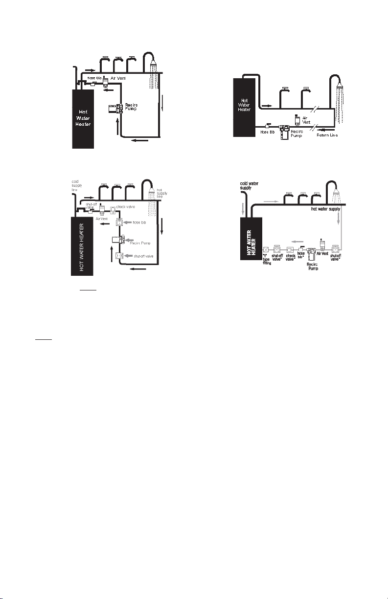
UC/UCT Models
A. Return into Cold Water Line at Top of Water
Heater fig. 1
B. Return to Drain Valve at Bottom of Water
Heater fig. 2
SM/SMT Models
A. Return into Cold Water Line at Top of Water
Heater fig. 3
B. Return to Drain Valve at Bottom of Water
Heater fig. 4
Note: The Air Vent and Hose Bib are not required with UC/UCT-01 models.
These models have a built-in air purge valve.
Above diagrams are for single line returns only. For multiple branched supply line installations, a
recirculation line should be installed for each branch.
Note: The pump must always be installed below the water level of water heater so that the pump flow
is always upward or directly horizontal and not downward. Do not mount the pump above the water
heater.
3. Purchase materials required.
• Laing ReCirc® (SM-303/353/UC-303/353 or SM-909/959) • (1)1/2”(5/8”) or 3/4” swing check valve
• Copper pipe or tubing (not required on UC/UCT models)
• Tee for under sink connect • (1) 1/2”(5/8”) or 3/4” hose bib/
• Tee or “Y” fitting connection to water heater connection (not required on UC/UCT-01
• (2) 1/2” (5/8”) or 3/4” shut-off valves models)
• Misc. nipples and fittings UC/UCT models) • (1) Auto air vent
• Pipe insulation (not required on UC/UCT-01 models)
4. Shut off the water to the house.
5. Drain the plumbing lines by opening the faucet/tap in the house. Drain the water heater if you plan
to make the connection at the bottom of the water heater, which requires removal of the drain valve.
6. Connect the return line at the last faucet/taps riser and run to the water heater. Tee the return line
as close to the end of the hot water supply line as possible and run the return line back to the water
heater.
7. Install the pump and other components required in accordance with the diagrams provided in fig. 1
or 2 and connect the return line to the water heater (also see fig. 3).
For SM(T) and UC(T) 303/353 Models Check pump operation before you begin. Unscrew the pump
housing from the motor (fig. 4) and run the pump for a few seconds to make sure it is operational.
Remove the rotor (see fig. 5) and add a little water to the bearing ball for lubrication. Do not use
grease or oil to lubricate the pump.
3
Page 4

UltraCirc Models
The UC and UCT-303/353 models incorporate a shut off valve and check valve into the brass pump
housing eliminating the need to install these components. Models with a 01 designation have a
built-in air bleeder valve. These models are supplied with 1/2” (5/8”) union fittings. These fittings
should be removed from the pump housing before soldering to avoid damaging the internal valves.
For SM(T) - 909/959 Models
This unit may be installed into the pipe system without disassembling the pump. However, it is
recommended that the motor section be disassembled from the pump housing by removing the two
pump housing screws so that the system may be flushed as noted in paragraph 9.
Fig. 4
Remove the motor unit and o-ring from the pump
housing into the plumbing line. Do not sweat the
housing into the plumbing line with the motor
or o-ring attached. Arrows on the pump housing
indicate the direction of water flow.
Fig. 5
303/353 Models - Rotor/Impeller Installation: To remove
the rotor unit, grasp the top of the unit and gently pull
straight up. Do not pull up on one side only or push the
rotor sideways. If the rotor sits too tightly, carefully lever
it off with a screwdriver on each side of the rotor. When
re-installing the rotor, use enough force to hear the rotor
“click” on to the ceramic bearing and spin the rotor with
your fingers to insure that it turns freely.
Caution: Only hand tighten the screw ring. Do
not over tighten! Do not use plumbers putty on
the screw ring.
Remove the Rotor/ Impeller
by using forefinger and
thumb and pulling upward.
Or, if the Rotor/Impeller cannot
be removed using forefinger and
thumb, carefully lever off evenly
with two screwdrivers.
For SM(T) - 909/959 Models
This unit may be installed into the pipe system without disassembling the pump. However, it is
recommended that the motor section be disassembled from the pump housing by removing the two
pump housing screws so that the system may be flushed as noted in paragraph 9.
Shut-Off Valve (allows isolation of water in the tank in the event of pump servicing). Hose Bib/
Connection (allows venting of air from system at start-up). Auto Air Vent (allows continuous venting
of air bubbles that intrude into all hot water circulating systems during operation).
8. Close the shut-off valve on the inlet side of the pump and turn the water supply back on.
9. Flush system of debris. Before reattaching the pump motor, open the
shut-off valve on the inlet side of the pump housing and let water flow
Correct Installation
through the housing. Use a bucket to catch the water. Let the water run
long enough to clear all sand, solder pellets, plumbers tape flakes, etc.
from the lines. Close the inlet shut-off valve when finished.
10. Connect the pump motor to the housing. Make sure the rubber
o-ring is in place in the housing and the screw ring is securely hand
tightened (for 303/353 models) or that the top housing screws
are firmly in place and tightened (909/959 models). Open the shut-off
valve or valves and let the water flood the pump housing.
11. Purge air from the supply line. Turn on the faucet/taps or shower
farthest from the water heater. Open the line until you get a good,
steady stream of water without sputter or evidence of air.
Improper Installation
Do NOT mount in these
orientations
12. Purge air from the return line. Connect the pump to the electrical supply. With the pump running,
open the hose bib/connection and let water run until the pump is running quietly and there is no
sputtering or other evidence of air coming from the hose bib. Close the hose bib. UC/UCT-303-01
models have a built-in air bleeder valve, use this valve to purge the return line of air. Your system is
now in operation. Allow a few minutes for instant hot water to recirculate to all of your faucet/taps.
SM-909/1212
SAFETY PRECAUTION: Remove the handle from the hose bib(s)/connection(s) to prevent a small child
from mistaking it for a water faucet/tap. Insulating both the hot water supply and recirculation lines is
strongly recommended.
4
Page 5

Wiring Diagrams for Units Not Supplied with a Cord.
SM-303 SMT-303
red
yellow
brown
black
white
red
black
13. If you have an SMT or UCT timer pump, set your timer in accordance with the instructions below.
Timer Controlled Operation
If timer controlled operation is desired, the timer may be programmed to allow the system to operate
during the hours desired (i.e. “ON” from 7:00 a.m. to 9:00 p.m. and “OFF” from 9:00 p.m. to 7:00
a.m.) as follows:
• Open the timer cover and rotate the dial clockwise
until the correct time is aligned with the pointer (P)
on the dial face. If the indicator cannot be located
on the face of the timer, there is an additional arrow
indicator (P) on the side of the timer. Be certain to
choose the correct “AM” or “PM” time.
• Pull all the tabs upward or outward during the time
you want the system to operate automatically. (Pull
the tabs “upward” on Timer Version A or push the
tabs outward on Timer Version B).
• On Timer Version A, each tab is a 30-minute increment. On Timer Version B, each tab is a
15-minute increment. As an example, if the desired time of operation is between 7:00 a.m. and
9:00 p.m., all of the tabs between 7:00 a.m. and 9:00 p.m. should be pulled upward or pushed
outward.
• Slide the switch bar to “timer”.
The timer mode will provide the most cost effective method of operation and can be programmed to
run only during the time periods when hot water is most frequently required.
green
red
yellow
red
brown
brown
red
black
black
white
green
Version A Version B
Does and Do Not’s
Do
• install an air vent mounted in a vertical position (if provided).
• use 1/2”(5/8”) recirculation line tubing.
• check to be sure there are no crimps or sharp bends in the recirculation line that would restrict the flow.
• be sure the check valve is installed in the proper direction of the flow.
• be sure all air is purged from the system prior to starting the pump.
• use a water conditioner if you have hard water.
• be sure the gate valves are open before turning on the pump.
• install the pump pumping in upward direction only.
Do Not
• use grease or oil to lubricate the pump - it is self-lubricating.
• over tighten the screw ring (SM/UC-303/353 models).
• install the pump with the motor above the pump housing.
• install the pump pumping away from the water heater nor pumping downward.
• start the pump before the system is full of water and purged of air.
• allow the water heater temperature above 140ºF (60ºC). (only in the US)
• install the pump in the supply line to faucet/taps.
• use any pipe size other than 1/2”(5/8”) for SM-303/353 (only in the US) or UC-303/353 models.
• position the pump at the top of the water heater.
5
Page 6

Notes:
Keep The Hot Water Temperature Below 140ºF (60ºC): Higher temperatures can cause calcium and
magnesium elements to come out of solution and create solids which could not only cause damage to the
pump but also reduce water heater efficiency and premature failure of the water heater.
Hard Water Conditions: Use a water conditioner. Hard water can cause scale build-up and eventually reduce
the life of the pump and other system components.
Standard Dry Run Thermostat Operation
Each SM(T)-303/353 and UC(T)-303/353 model pump has a built-in 200ºF (93ºC) thermal cut-off in order
to protect against overheating, which could cause damage to the pump motor. In the event that
disruption of your immediate hot water supply is noticed it is possible that the pump has or is running dry
and the internal dry run thermal protector has shut down the pump motor. In this event, it is important
that the dry run condition be corrected (otherwise the pump will fail prematurely) by following the
procedure below:
1. Disconnect power to the pump motor.
2. Close the shut-off valves on each side of the pump.
3. Remove the pump motor/rotor assembly from the pump housing.
4. Dry off the pump motor/rotor assembly. Remove the rotor and check for any calcium build-up,
foreign matter or any signs of wear. If these signs are not present, put the rotor back in place on the
ceramic ball.
5. Hold the pump motor/rotor assembly upright and plug in the unit for about 10 seconds to see if the
rotor spins evenly and quietly. If the motor does not go on, allow a few more minutes for the
thermostat to reset as the unit cools down.
6. If the rotor spins properly, unplug the motor and reinstall the assembly into the pump housing.
7. Turn both shut-off valves to the on position, reconnect the electrical supply to the pump motor, and
be sure that air is properly purged from your system.
130ºF (54ºC) On-Off Thermostat Option “C”
Pumps with the letter “C” in the model are provided with a factory option “C” internal thermal cut-off
which automatically shuts the pump down when the temperature of the water passing through the
pump housing reaches 130ºF +/- 10ºF (54ºC +/- 4ºC) and turns the pump on at 110ºF +/- 10ºF (43ºC
+/- 4ºC) (SM/SMT 909/959-14 only).
Variable Setting On-Off Thermostat Option “R”
Pumps with the letter “R” in the model designation are provided with a factory installed internal thermal
cut-off with an adjustable On-Off temperature dial located on the outside of the motor. This dial can be
rotated by placing a thin screw driver in the dial slot which allows the pump to turn off automatically
when the water temperature passing through the pump housing reaches the dial setting selected
between 95ºF (35ºC) and 140ºF (60ºC). The pump will turn back on automatically when the water
temperature cools down to 10ºF (4ºC) below the set temperature (SM/SMT-303/353 only).
System Maintenance
• Do not attempt to lubricate the pump. The pump is self-lubricating.
• Prevent the pump from running dry.
• Flush the system of any debris and re-purge all air from the system in the event of any water supply
interruptions in plumbing line.
• Prevent heavy scale build-up by keeping the hot water temperature 140ºF (60ºC) or less. (only in US)
• Don’t over salt your water conditioner.
Replacement Parts
Please provide the following information when ordering: Model and Serial number and Part description
A - Housing
B - “O” Ring
C - Rotor Assembly
D - Motor Assembly
E - Screw Ring
6
A
B
C
D
E
Page 7

Trouble Shooting
Noise in the System: The pump should be virtually noiseless during operation. The rotor may make a
brief but hardly perceptible fluttering noise immediately after the pump is turned off. During normal
operation, an occasional air bubble may pass through the pump housing causing a momentary
gurgling noise. However, if noise at the pump persists for any prolonged period, correct the problem
(see below).
• The check valve/non-return valve is mistakenly installed on the inlet side of pump or in the wrong
direction. The check valve refers to a swing check not a spring check.
• The inlet side shut-off valve is closed or clogged.
• There is air is trapped in the pump housing (turn the pump on and off several times to see if the air
pocket can be “bumped” out of the pump and if not, then open the hose bib for manual venting).
• There is debris blocking the rotor.
• The rotor bearing has worn due to dry running causing the rotor to wobble during operation.
• If the return line connects to the cold water supply at the top of water heater, the warm water may
be creating back pressure in the cold supply line. If so, add a check valve/non-return valve on the
cold supply line above the return line tee connector.
Pump Operating Intermittently or Not at All:
• No power to the pump.
• There is debris or foreign matter in the pump.
• The thermostat is not functioning properly (see page 6 on thermostat operation).
Water Taking Too Long to Get to Faucet/Tap:
• The hot water supply from the water heater is exhausted.
• The faucet/tap involved may be on a branch line off the main hot water supply line in which case
there may be a slightly longer wait for hot water to arrive than at faucet/tap directly off the main
supply line.
• The check valve/non-return valve is installed backwards.
• The pump is not operating.
• The timer is not operating properly.
Signs of Dry Run:
Dry run results from inadequate water supply to the pump, which prevents lubrication of the bearing ball.
It may be caused by operating the pump without water in the plumbing lines, which may occur with frozen
pipes, or by failing to turn the pump off when the system is drained for servicing. It can also occur as the
result of large air bubbles collecting in the pump housing and preventing the flow of water over the bearing
ball. If the problem is air in the system, check that the air vent is functioning, that the system is properly
purged of air.
Warranty
Laing recirculation pumps are warranted against defects in materials and workmanship for 24 months from
the date of manufacture (see mfg. date label on pump) or twelve (12) months from date of user purchase,
with proof of purchase, whichever is later. In order to receive warranty considerations, the product must be
returned prepaid to the company from which it was originally purchased. If the pump is found defective, the
pump will be replaced or in the case of wholesale customers, appropriate purchase credit will be issued. Prior
to returning any defective pump to Laing for warranty consideration, contact the Laing factory for an RMA
tracking number. Any claim for consequential damages resulting from a pump malfunction is not covered by
the Laing warranty. Additional warranty details are available on request
.
Safety Requirements
Mechanical Safety
WARNING: - Excessive System Pressure Hazard - The maximum working pressure of the
pump is listed on the nameplate - Do Not Exceed This Pressure. Failure to follow these
instructions could result in serious personal injury, death and/or property damage.
WARNING: - Excessive Pressure Hazard Volumetric Expansion - The heating of water and
other fluids causes volumetric expansion. The associated forces may cause failure of system
components and the release of high temperature fluids. This can be prevented by installing
properly sized and located compression tanks and pressure relief valves. Failure to follow
these instructions could result in serious personal injury, death and/or property damage.
7
Page 8

Thermal Safety
WARNING: - Extreme Temperature Hazard - If the pump, motor or piping are operating at
extremely high or low temperature, guarding or insulation is required. Failure to follow these
instructions could result in serious personal injury, death and/or property damage.
Electrical Safety
WARNING: - Electrical Shock Hazard - Electrical connections are to be made by a qualified
electrician in accordance with all applicable codes, ordinances and good practices. Failure
to follow these instructions could result in serious personal injury, death and/or property
damage.
WARNING: - Electrical Grounding Hazard - Adequate electrical grounding is required for
the safe operation of Laing Pumps. Ground the pump back to the service using a copper
conductor at least the size of the circuit connectors supplying the pump. Connect the ground
wire to the ground terminal in the wiring compartment. Failure to follow these instructions
could result in serious personal injury, death and/or property damage.
WARNING: - Risk of Electric Shock - Do not install this pump in swimming pool or marine
areas. Failure to follow these instructions could result in serious personal injury, death and/or
property damage.
Removal of Pump From Existing System For Replacement
WARNING: - Electrical Shock Hazard - Disconnect and lockout the power before
servicing. Failure to follow these instructions could result in serious personal injury, death
and/or property damage.
1. Close the valves on the suction and discharge sides of the pump. (if no valves have been installed, it
may be necessary to drain the system.)
2. Disconnect the electrical supply lines to the pump.
WARNING: - Hot Water Hazard - Before draining the system, allow water to cool to at least
100F, open the drain valve (take precautions against water damage) and leave the drain valve
open until servicing is complete. Failure to follow these instructions could result in serious
personal injury, death and/or property damage.
WARNING: - Electrical Shock Hazard - Be certain the electrical power is not present at the
motor leads before continuing. Failure to follow these instructions could result in serious
personal injury, death and/or property damage.
WARNING: - High Pressure Hazard - Pressure may be present in the pump body. This
pressure can be relieved by loosening the flange bolts and shifting the pump assembly
slightly to allow the pressurized water to escape. Failure to follow these instructions could
result in serious personal injury and death.
Copyright © 2009 ITT Corporation,
Printed in the U.S.A 1-10 IM-16
THE ITT ENGINEERED BLOCKS
SYMBOL AND ENGINEERED FOR LIFE
ARE REGISTERED TRADEMARKS OF
ITT MANUFACTURING
ENTERPRISES, INC.
ITT
3878 S. Willow, Suite 104
Fresno, CA 93725
Tel: (559) 265-4730 (800) 554-6853
Fax: (559) 265-4740 (800) 453-7523
www.lainginc.com
8
 Loading...