


Operating Instructions
HV 2.015 / 2.022
HV 4.022 / 4.030 / 4.040
HV 4.055 / 4.075 / 4.110
V 2012/03A-V01.4
HV 4.150 / 4.185 / 4.220
771079412 Manual HV 2.015-4.220 ENGLISH


Index
1 Important safety instructions...................................................................................5
2 System design ...........................................................................................................8
2.1 Pressure tank ................................................................................................8
3 Product overview......................................................................................................9
3.1 Hardware configurations .............................................................................9
3.2 Operating modes..........................................................................................9
3.2.1 Actuator (for SINGLE pump operation only!) .......................................................... 9
3.2.2 Controller................................................................................................................ 9
3.2.3 Cascade Serial / Synchronous (not for SINGLE version).......................................... 10
3.2.4 Cascade Relay (not for SINGLE version)................................................................. 12
4 Type designation code............................................................................................13
5 Technical Data.........................................................................................................14
5.1 General technical data ...............................................................................15
5.2 EMC requirements (Electromagnetic compatibility)..................................16
6 Dimensions and weights ........................................................................................17
7 Modules 20
8 Mechanical components .........................................................................................22
8.1 Included mounting material ......................................................................22
8.2 Optional components.................................................................................22
8.2.1 Mounting accessories ........................................................................................... 22
8.2.2 Sensors ................................................................................................................. 22
8.2.3 Filter ..................................................................................................................... 22
• Line-coils ........................................................................................................................... 22
8.2.4 Cable entry (only HV4.150 – 4.220) ...................................................................... 22
8.2.5 Ready-made motor cables..................................................................................... 22
8.3 Assembly instructions ................................................................................23
9 Electrical installation and wiring ............................................................................25
9.1 Means of protection...................................................................................25
9.2 EMC-electromagnetic compatibility...........................................................26
9.3 Recommended Cable Types .......................................................................27
9.4 Wiring and connections .............................................................................28
9.4.1 Main voltage terminals ......................................................................................... 29
9.4.2 Motor connection................................................................................................. 30
9.4.3 Power unit ...................................................... Errore. Il segnalibro non è definito.
9.4.3.1 Solo run................................................................................................. 32
9.4.3.2 Addressing............................................................................................. 34
9.4.4 RFI – switch........................................................................................................... 36
9.4.5 Control unit .......................................................................................................... 37
9.4.5.1 Control card – HYDROVAR MASTER Inverter .......................................... 37
9.4.5.2 Relay Card.............................................................................................. 44
3

9.4.5.3 Control card – HYDROVAR SINGLE Inverter (not for HV 4.150 – HV
4.220) 46
10 Programming ........................................................................................................49
10.1 Display – Control panel of the MASTER / SINGLE Inverter .........................49
10.2 Function of the push buttons ....................................................................49
10.3 Display of the BASIC Inverter .....................................................................50
10.4 Software parameters..................................................................................51
00 MAIN MENU ....................................................................................................51
20 SUBMENU STATUS ...........................................................................................56
40 SUBMENU DIAGNOSTICS .................................................................................59
60 SUBMENU SETTINGS........................................................................................60
0100 SUBMENU BASIC SETTINGS .........................................................................61
0200 SUBMENU CONF INVERTER..........................................................................64
0300 SUBMENU REGULATION ..............................................................................72
0400 SUBMENU SENSOR ......................................................................................74
0500 SUBMENU SEQUENCE CNTR. .......................................................................77
0600 SUBMENU ERRORS ......................................................................................82
0700 SUBMENU OUTPUTS ....................................................................................83
0800 SUBMENU REQUIRED VALUES .....................................................................84
0900 SUBMENU OFFSET .......................................................................................86
1000 SUBMENU TEST RUN....................................................................................89
1100 SUBMENU SETUP .........................................................................................90
1200 SUBMENU RS485-INTERFACE.......................................................................91
11 Failure messages...................................................................................................92
11.1 BASIC Inverter.............................................................................................93
11.2 MASTER / SINGLE Inverter ..........................................................................94
11.3 Internal errors.............................................................................................97
Maintenance ..............................................................................................................99
Programming flow chart ........................................................................................ 100
Follow the pump operating and maintenance instructions
We reserve the right to alter specifications
4

1 Important safety instructions
Read and follow the operating and safety instructions carefully
before starting operations!
All modifications must be done by qualified technicians!
Warning that failure to observe the precaution may cause electric shock
Warning that failure to observe the precaution may cause personal injury or
damage to property.
In addition to these operating instructions please pay attention to universal safety
and accident prevention regulations.
Basically the HYDROVAR must be disconnected from the power supply before any work can
be carried out on the electrical or mechanical part of the system.
Installation, maintenance and repair work may be carried out only by trained, skilled and
qualified personnel.
Unauthorized modification or changes to the system make all guarantees null and void.
During operation, the motor can be stopped by opening a digital input or manual
operation whereby the HYDROVAR and the motor remain under voltage. For safety
reasons, the HYDROVAR has to be disconnected from the power supply when carrying out
work on the machinery.
When the HYDROVAR is connected to the power supply, the components of
the power unit as well as certain components of the control unit are
connected directly to mains.
Touching these components seriously endangers life!
Before removing the HYDROVAR cover the system must be disconnected from
the power supply. After switching off the power supply wait
at least 5 minutes before starting work on or in the HYDROVAR (the
capacitors in the intermediate circuit are discharged by the internal discharge
resistors).
Voltages of up to 800 volts are possible (in case of error these also can be
higher)
5

All work, carried out on the HYDROVAR, may only be performed by
qualified and authorized staff.
Furthermore, take care not to short circuit the neighbouring
components when connecting the external control wires. All cable ends which
are not in use have to be isolated.
The HYDROVAR contains electronic safety devices which switch off the control
element in the event of a fault, whereby the motor has zero current but
remains energised and comes to a halt. The motor can also be halted by
mechanical blocking. If it is switched off electronically the motor is current
less from the mains voltage through the electronics of the HYDROVAR but is
not potential-free in the circuit.
In addition voltage fluctuations, especially power failures can cause the
system to switch itself off.
Repair of faults can cause the motor to start up again automatically!
The system may only be put into operation when it has been grounded.
In addition to that, equipotential bonding of all conductive pipes must be
ensured.
Please consider local installation standards!
High voltage tests of the HYDROVAR or the motor may damage the
electronic components! Hence bridge the in- and outgoing
terminals L1 - L2 - L3 / U-V-W before.
To avoid incorrect metering by capacitors incorporated in the electronic
part isolate the motor from the HYDROVAR.
The operating instructions must be read, understood and
followed by the operating personnel. We point out that we
accept no liability for damage and operating disorders
which are the result of non-compliance with the operating
instructions.
6

Transport, handling, storage, disposal:
• Check the HYDROVAR immediately after delivery/receipt for damage or missing parts
• The HYDROVAR unit must be transported carefully.
• Avoid serious impacts
NOTICE!
Dispose of all packing materials and the HYDROVAR unit in accordance with
local regulations. For more detailed information about the recycling of this
product, please contact your local authority, your waste disposal service
provider or the outlet where you purchased the product.
CAUTION!
Lifting aids (stacker, crane, crane mounting device, lifting blocks, sling
ropes, etc.) must be suitable to handle the weight of the HYDROVAR.
CAUTION!
It is not allowed to carry the HYDROVAR around by using the connected
cables.
Do not damage the cable during transport (do not squeeze, bend or drag).
The cable ends must be kept dry.
WARNING!
• Do not stand underneath suspended loads
• Take note of the general regulations on prevention of accidents
• The HYDROVAR must be secured against tipping over and slipping until
it has been fixed in its final location.
7

2 System design
The following diagrams show typical SINGLE and multi-pump systems using the
HYDROVAR. Connection can be made directly to a water supply. In such a case, the use of a
low pressure switch on the suction is recommended.
SINGLE pump layout Multi pump layout
(1) pump with HYDROVAR
(2) diaphragm tank
(3) distribution panel
(4) gate valve
(5) non return valve
(6) low water control
(7) pressure gauge
(8) pressure transmitter
(9) drain tap
2.1 Pressure tank
A diaphragm pressure tank is used on the discharge side of the pump to maintain pressure
in the line when there is no water demand. This avoids the pump from continuing to run at
zero demand. With the HYDROVAR, no large tanks are required for supply purposes.
The tank must be permitted and suitable for systems pressure. The tank should have a
capacity of min. 10% of the maximum system flow rate [l/min] of one pump (also valid for
multi-pump system).
Example:
Maximum flow rate of the pump = 250 litres per minute
Minimum volume of the tank = 250 x 0.10 = 25 litres
The pre-charge pressure of the tank can be determined by using the following table:
required pressure [bar]
pre-charge pressure [bar]
NOTICE:
To check and set the right pre-charge pressure, please reduce the water
pressure to zero by turning the HYDROVAR off.
8

3 Product overview
3.1 Hardware configurations
The HYDROVAR modular concept basically consists of two main parts: the power unit and
the control card. In its BASIC configuration (consisting of only the power unit) the
HYDROVAR can be used as so called BASIC Inverter. In that configuration the HYDROVAR
can be used as a sequence pump in a multi pump system, but also as a simple soft starter
for SINGLE pump applications.
By attaching one of the additional control cards to the BASIC Inverter the HYDROVAR can
be upgraded either to the so called SINGLE or the MASTER Inverter.
BASIC Inverter – HYDROVAR BASIC unit (not available for HV 4.150 – 4.220).
Application:
- Sequence pump in a multi pump system, SINGLE pump operation as soft-starter
SINGLE Inverter – HYDROVAR BASIC Inverter with included control card for SINGLE pump
operation. This SINGLE Inverter is not able to support any optional modules like the Relay
Card.
Application:
- Simple SINGLE pump applications
MASTER Inverter – HYDROVAR BASIC Inverter including the high level control card
(supports also the optional modules like the Relay Card and all specific software features).
Application:
- SINGLE pump control including all extended features
- Multi pump system of MASTER and BASIC Inverters (up to 8 pumps)
- Multi pump system equipped with up to 8 MASTER Inverters
- Control of up to 5 fixed speed pumps when used in combination with the optional relay
card
3.2 Operating modes
3.2.1 Actuator (for SINGLE pump operation only!)
In this mode the HYDROVAR operates as an actuator according an external speed signal or
continuous operation on either one or two programmed frequencies by using the
corresponding digital input.
Please consider that this mode is only possible with a HYDROVAR MASTER or SINGLE
Inverter and is limited for SINGLE pump operation only
3.2.2 Controller
This mode is set as default operating mode and is used for a HYDROVAR in SINGLE pump
operation when there is no connection to any other HYDROVAR via the internal RS485
interface.
9

3.2.3 Cascade Serial / Synchronous (not for SINGLE version)
In these modes various combinations among the versions BASIC and MASTER Inverter are
possible.
In general each of the pumps needs to be equipped with a HYDROVAR unit. All the units
are connected via the RS485 interface and communicate via the standard MODBUSprotocol (9600 Baud, RTU, N81).
To realise a fully controlled system at least one MASTER Inverter is needed, the remaining
pumps could be fitted just with a BASIC Inverter.
The controller in the MASTER Inverter is continuously in communication with all the BASIC
Inverters. All failures are indicated on the MASTER including the date and time.
All the control is done by the MASTER Inverter including automatic change over of the lag
pumps to provide even wear and achieve even operating hours.
If the control card of a MASTER Inverter fails, each of the BASIC Inverters can be manually
started by an external switch (manual operation) in order to ensure an emergency
operation of the system.
Application Example
Each pump of the system (up to 8 pumps) is equipped with a HYDROVAR unit (at least one
MASTER Inverter and remaining ones can be BASIC Inverters). All units are connected via
the serial interface (RS485).
The combination of the different HYDROVAR units which are used in a multi-pump-system
depends on the system requirements (i.e. in a 6 pump system 2 MASTER Inverters can be
used due to reliability reasons and 4 BASIC Inverters without control card – or just any
other combination).
Minimum requirement: 1 MASTER Inverter and the other pumps equipped with BASIC
Inverters
10

To increase the operating reliability of such a system, also a second MASTER Inverter is
recommended:
Full-featured possibility: Each pump is equipped with a MASTER Inverter
In this mode it is possible to run all pumps in cascade serial mode and synchronous mode
as well.
This configuration allows each pump of the system to become the lead pump. This also
ensures a proper operation if one MASTER Inverter fails. In this case another HYDROVAR
takes control. This ensures that the operating hours of each pump will be the same to
ensure even wear of the pumps.
11

3.2.4 Cascade Relay (not for SINGLE version)
One pump is fitted with a HYDROVAR MASTER Inverter and up to 5 slave pumps can be
switched ON and OFF on demand. For this purpose an additional relay card including 5
relays is attached to the MASTER Inverter.
However an external switchboard is needed for all the motor relays as the relays in the
HYDROVAR are not able to switch the pumps directly (just used as control contacts).
Also an automatic change over of the fixed speed pumps to provide even wear and achieve
even operating hours is possible in this mode.
This configuration is a cost effective alternative compared with other solutions using VFD’s
on each pump, but in any case care has to be taken due to the lower reliability of such a
system.
Application example
Booster sets up to 6 pumps where only one pump is speed controlled by the HYDROVAR
and the others are fixed speed (1 HYDROVAR MASTER Inverter+5 fixed speed).
12
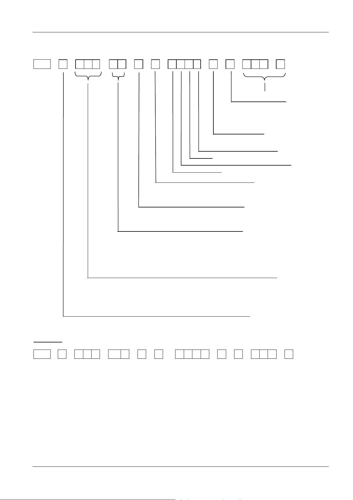
4 Type designation code
HV . - - - - - - - .
Software version
1 = Western Europe resp. all lang.
3 = Eastern/Northern Europe
Hardware version
Optional components
Relay Card (0= without / R= included)
Display (0= without / 1= included)
EMC protection filter
A = A- Filter (industrial environment)
B = B- Filter (domestic environment)
Language
(with V01.4)
Optional card
Bus card
Enclosure class (IP Class)
2= IP 21
5= IP 55
Hardware configurations
M = Motor mounted unit
W = Wall mounted unit
1= BASIC Inverter
2= SINGLE Inverter
3= MASTER Inverter
Rated output
022= 2,2 kW 055= 5,5 kW
030= 3,0 kW 075= 7,5 kW
040= 4,0 kW 110= 11kW
150=15,0kW 185=18,5kW 220=22,0kW
Nominal mains voltage
1= 1~/1~ 230VAC 3= 3~/3~ 230VAC
2= 1~/3~ 230VAC 4= 3~/3~ 380-460VAC
Example
HV 4 . 0 4 0 - M 3 - 5 - B - 1 0 R 0 - G- 1 - V 0 1 . 4
The mentioned HYDROVAR in this example is specified with following technical data:
Nominal mains voltage: 3~/3~ 380-460VAC
Rated output: 4 kW
Hardware configurations: Motor mounted unit - MASTER Inverter
Enclosure class: IP 55
EMC-filter: B - Filter (domestic environment)
Optional components: Display, Relay Card
Hardware version: G
Language: 1 (Western Europe) respectively all languages
Software version: V01.4
13
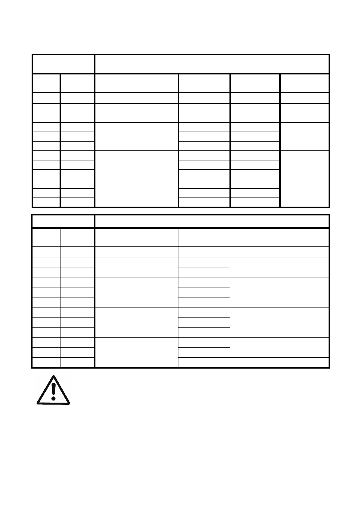
5 Technical Data
HYDROVAR
type rated
output
Incoming power supply (data only for dimensioning of the power
supply line and not for calculating the efficiency of the HV)
Voltage limits
48-62 Hz
nominal
current input
recommended
line protection
maximum
cross-section
HV [kW] [V] [A] [A] [mm²]
2.015 1,5 14,0 20
2.022 2,2
1~230 ± 15%
20,0 25
4
4.022 2,2 7,4 13
4.030 3 9,1 13
4.040 4
3~380-460 ± 15%
11,7 16
4
4.055 5,5 17,5 20
4.075 7,5 22,1 25
4.110 11
3~380-460 ± 15%
29,9 32
4
4.150 15 39,0 50
4.185 18,5 48,1 50
4.220 22
3x380-460 ± 15%
55,9 63
25
HYDROVAR Output to the motor
type rated
output
max. output voltage nominal
current output
motor connection cables
HV [kW] [V] [A] mm²
2.015 1,5 7,0
2.022 2,2
3x Uin
10,0
4x1,5 – 4x4
4.022 2,2 5,7
4.030 3 7,3
4.040 4
3x Uin
4x1,5 – 4x4
9,0
4.055 5,5 13,5
4.075 7,5 17,0
4.110 11
4.150 15 30,0
4.185 18,5 37,0
4.220 22
3x Uin
3x Uin
4x2,5 – 4x4
23,0
4x6 – 4x25
43,0 4x10 – 4x25
Make sure that the electrical data of the HYDROVAR match those of the
electric pump. Improper combinations may cause errors and malfunction of
the protection of the electric motor.
The nominal current of the motor must be lower than the rated current of the
HYDROVAR to prevent overheating or shutdown due to OVERLOAD.
The max. output current of the HYDROVAR could reach 110% of the nominal current for
max. 60 sec. before the error OVERLOAD will occur.
14

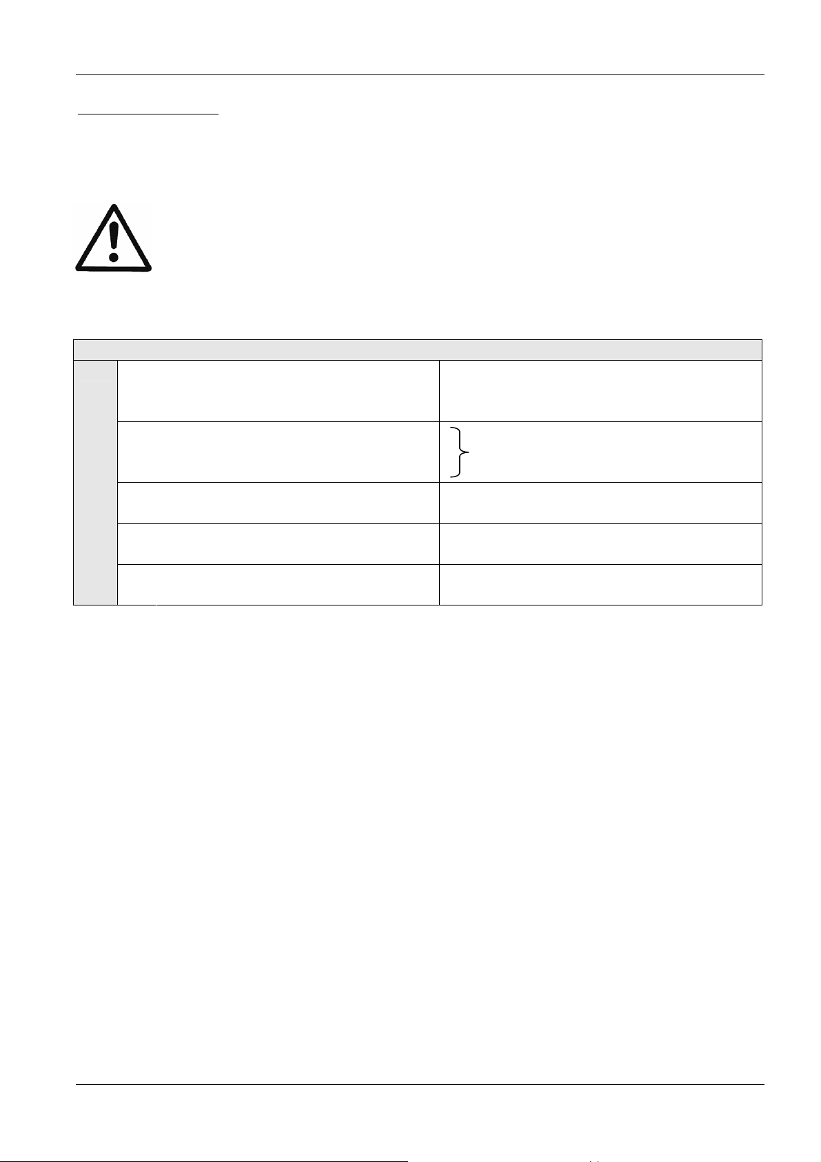
5.1 General technical data
Ambient temperature:
0° C ... +40°C
At higher temperatures a reduction of the output current or the
use of the next HYDROVAR power size is necessary.
110
100
90
80
70
60
50
40
max. output current [%]
30
20
10
0
0 102030405060
The insulation rating of the HYDROVAR is IP55 however and in
common with other IP55 equipment, please note the following:
• Protect the HYDROVAR from direct sunlight!
• Protect the HYDROVAR from direct rainfall
• Outdoor installation without protection to keep especially
the temperature limits of the HYDROVAR is not permitted!
max. ambient temperature [°C]
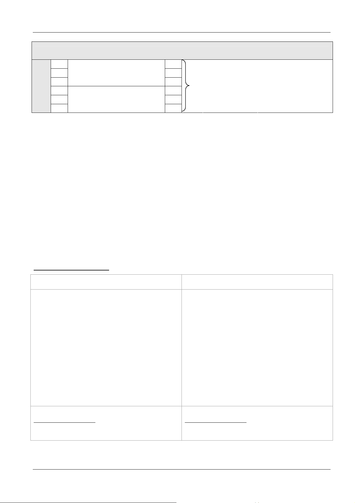
Storage temperature:
Humidity:
Air pollution:
Altitude:
Class of protection:
-25° C ... +55° C (+70°C during 24 hours max.)
RH max. 50% at 40°C, unlimited
RH max. 90% at 20°C, max. 30 days per year
75% average per year (class F)
Condensation is not permitted!
During long periods of inactivity or shutdown, the HYDROVAR
should remain connected to the power supply but the ext on/off
inhibited to prevent running of the pump. This will maintain
power to the internal heater and reduce internal condensation.
The air may contain dry dust as found in workshops where there
is excessive dust due to machines.
Excessive amounts of dust, acids, corrosive gases, salts etc. are
not permitted
Max. 1000m above sea level
For installations over 1000 m above sea level, the maximum
output power has to be de-rated by 1% for every additional
100m.
If the installation site is over 2000 m above sea level, please
contact your local distributor or service contact.
HV 2.015 / 2.022
HV 4.022 / 4.030 / 4.040 IP 55, NEMA 4 (indoor use only)
HV 4.055 / 4.075 / 4.110
HV 4.150 / 4.185 / 4.220
Certifications:
CE, UL, C-Tick, cUL
15

5.2 EMC requirements (Electromagnetic compatibility)
The EMC requirements in general differ between two environments which depending on
the intended use.
• First environment – class B (EN 61800-3: Class C2)
Environment that includes domestic premises, it also includes establishments directly
connected without intermediate transformers to a low-voltage power supply network
which supplies buildings used for domestic purposes e.g. houses, apartments, commercial
premises or offices in a residential building are typical examples of first environment
locations.
Be careful: The relevant EMC regulations for which the HYDROVAR is tested in the first
environment consider that the HYDROVAR is a restricted available product. That means the
voltage of the inverter is less than 1000 V, it is neither a plug in device nor a movable
device and, when used in the first environment, is intended to be installed and
commissioned only by a person or an organisation having necessary skills in installing
and/or commissioning power drive systems, including their EMC aspects.
• Second environment – class A (EN 61800-3: Class C3)
Environment that includes all establishments other than those directly connected to a low
voltage power supply network which supplies buildings used for domestic purposes e.g.
Industrial areas, technical areas of any building fed from a dedicated transformer are
typical examples of second environment locations.
The HYDROVAR complies with the general EMC regulations and is tested according
to the following standards: EN 61800-3/2004
EN 55011 (2002) Disturbance voltages / Disturbance field strength
First environment
– class B / class C2
Second Environment
– class A / class C3
Disturbance voltages OK OK
Disturbance field strength *) OK
*) Warning - In a domestic environment, this product may cause radio interference, in which case
supplementary mitigation measures may be required.
EN 61000-4-2 (2001) Electrostatic discharge
EN 61000-4-3 (2002) Electromagnetic field immunity test
EN 61000-4-4 (2001) Burst immunity test
EN 61000-4-5 (2001) Surge immunity test
EN 61000-4-6 (1996) Immunity of conducted RF-Disturbance
16

6 Dimensions and weights
HV 2.015 / 2.022
HV 4.022 / 4.030 / 4.040
All dimensions in millimetres! Drawings are not to scale!
Lifting aids must have the proper dimensions.
Type Weight [kg]
BASIC
MASTER /
SINGLE
HV 2.015
HV 2.022
HV 4.022
4,00 4,40
HV 4.030
HV 4.040
a … minimum centre-distance between HYDROVAR units 300 [mm]
b … expansion space for maintenance 300 [mm]
17

HV 4.055 / 4.075 / 4.110
All dimensions in millimetres! Drawings are not to scale!
Lifting aids must have the proper dimensions.
Type Weight [kg]
BASIC
HV 4.055
HV 4.075
7,70 8,10
HV 4.110
a … minimum centre-distance between HYDROVAR units 430 [mm]
b … expansion space for maintenance 300 [mm]
MASTER /
SINGLE
18

HV 4.150 / 4.185 / 4.220
All dimensions in millimetres! Drawings are not to scale!
Lifting aids must have the proper dimensions.
Type Weight [kg]
MASTER
HV 4.150
HV 4.185
14,00
HV 4.220
a … minimum centre-distance between HYDROVAR 550 [mm]
b … expansion space for maintenance 300 [mm]
19

5
1 2 3
7 Modules
Regarding the application the specific configuration for the HYDROVAR can be chosen. Due
to this possibility the HYDROVAR can be configured regarding the reliability and cost
effectiveness for each type of application.
HV 4.022 / 4.030 / 4.040 HV 4.055 / 4.075 / 4.110
6
4
HV 4.150 / 4.185 / 4.220
6
4
1
5
20

Power unit
Without one of the control cards it can be used as BASIC Inverter or as simple soft
(1)
starter in a SINGLE pump application!
When using a SINGLE or MASTER configuration the power unit is fitted with an
additional control card (4)
(2)
(3)
(4)
(5)
(6)
Filter card (not available for HV4.150-4.220, standard is class A)
Ensures EMC compliance for domestic environments. (Class B)
Mounting Kit
Consists of the metal and plastic cover to fix the control card and the display (and
the additional Relay Card if used). By the pre-mounted cable-clips, the screen of all
signal cables has to be connected to HYDROVAR-ground to avoid any interferences
on the signals
Control card
either for MASTER or SINGLE Inverter
Display unit
2 line plain text indication for programming and read out.
Relay Card
The optional Relay Card allows to control up to 5 fixed speed pumps (can be only
used in combination with the MASTER Inverter).
21

8 Mechanical components
8.1 Included mounting material
Included
components
M M M M M M M M
12 16 20 25 40 12 16 50
Cable diameter
[mm]
2.015 – 2.022
4.022 – 4.040
4.055 – 4.110
4.150 – 4.185 4 (5) 2 2 4 2 1 1 4 1
4.220 4 (5) 2 2 4 2 1 1 4 1
( ) max. available cable entries
2 (3) 2 2
2 (3)
2 (3)
Cable gland +
Lock nut
7 - 13
3,7 - 7
4,5 - 10
2 2 3 1 1 4 1
2 2 3 1 1 4 1
9 - 17
15 - 23
3 1 1 4 1
closing glad Motor
PTC
Mounting
clamps
Centring
bit
8.2 Optional components
8.2.1 Mounting accessories
Mounting ring
Available for diameters: 140 mm
155 mm
CAUTION!
If the HYDROVAR is mounted on a
motor with a plastic fan cover, a
stainless-steel mounting ring must be
used to support the weight of the
HYDROVAR.
8.2.2 Sensors
• pressure-transducer • temperature-sensor
• differential-pressure-transducer • flow indicator
• level-sensor
(orifice plate, inductive flow meter)
8.2.3 Filter
• Line-coils
8.2.4 Cable entry (only HV4.150 – 4.220)
• Multiple cable entry (M50)
8.2.5 Ready-made motor cables
Available for HV 2.015 – 4.220
22

8.3 Assembly instructions
HV 2.015 – HV 4.110 HV 4.150 – HV 4.220
4 screws (to fit cover)
M4x50 M5x20
HYDROVAR – top cover
4 screws
M6x70
4 screws
M5x70
display
centering bit
4 mounting clamps
motor cable
motor fan cover
motor
motor conduit box
PTC
actual value sensor
23

A
To remove the HYDROVAR – cover, the 4 fastening screws must be opened.
• Ensure that there is no liquid on the unit before you open the cover.
• Centre the HYDROVAR on the motor fan cover using the rubber centre bit.
•
If the HYDROVAR is mounted on a motor with plastic fan cover, a stainless
steel mounting ring must be used.
• The HYDROVAR is installed on the motor fan cover by using the mounting brackets, the
four screws and the relevant washers*.
• The HYDROVAR has to be centred and then the four screws must be tightened.
• Tighten each fastening screw until the two bottom teeth in the brackets start to grip the
fan cover.
• After the electrical components are connected, the top cover of the HYDROVAR can be
mounted and tightened by the four fastening screws.
• Make sure of a good connection of the ground wire.
• Ensure HYDROVAR cover gasket is in place before tightening the fastening screws.
• Ensure that the mounting of the cable glands is done properly and use closing plugs
for cable entries which are not in use.
*For HV4.150-4.220: Measure the right distance with the acceptance, the clamp and
the screw together
Max. Length
Adjust the length for smaller motor sizes
djust the length for smaller motor
sizes
Please take care about sharp edges and
remove them properly
24

9 Electrical installation and wiring
All installations and maintenance has to be performed by properly
trained and qualified personnel with proper tools!!
Use personal protection equipment.
In case of a failure, the electrical power has to be disconnected or
switched off. Wait at least 5 minutes for capacitor discharge before
servicing the HYDROVAR.
Otherwise it can cause shock, burns or death.
9.1 Means of protection
Ask your power supply company which means of protection are required.
Applicable:
• protective earthing
• AC and DC residual current operated protective devices (RCD)
• TN systems
Protective earthing:
• Please note that a current to earth can occur due to the capacitors in the input filter.
• A suitable protection unit has to be selected (according local regulations).
Residual current device (RCD/RCCB):
• When using an RCD, make sure that it also releases in the event of a short circuit inside
the DC-part of the HYDROVAR to earth!
o SINGLE phase HYDROVAR => use pulse sensitive RCDs
o three phase HYDROVAR => use AC/DC sensitive RCDs
• The RCD has to be installed according local regulations!
Automatic circuit breaker:
• Use automatic circuit breaker with C-type characteristic curve
• Rating of the line-protection (see chapter Technical Data)
Internal protective devices of the HYDROVAR:
• The malfunctions short circuit, under- and overvoltage, overload and the
overheating of the electronic components are monitored internally by the
HYDROVAR.
External protective devices:
• Additional protective functions like motor overheat and low water protection, are
controlled by external equipment.
25

9.2 EMC-electromagnetic compatibility
To ensure the electromagnetic compatibility the following points must be observed for
cable installation:
Earth / ground to ensure EMC
• Protection earth
It is important to connect the HYDROVAR to PE, because of the earth leakage
current.
• HF earth connection
Ground cables should be as short as possible and with lowest impedance.
Signal cables
Control and signal cables should be screened types to prevent disturbances from outside.
The screen should be only connected to ground on one end; to prevent ground loops. The
screen should be connected to HYDROVAR GND (use pre mounted cable-clips).
For small cable diameters the cable clips can be squeezed to ensure fixing.
Pre-mounted cable-clips
To connect a screen with lowest impedance to ground, remove the insulation from the
signal cable and connect the screen to ground.
Signal cables must be installed separate from motor- and power- supply cables
If signal cables are installed in parallel to power supply cables (motor cables) for a longer
distance, the distance between these cables should be more than 200mm.
Do not cross power cables and control cables - if this is not possible, cross them only in an
angle of 90°.
26

Motor cables
To ensure the EMC compatibility and minimize noise level and leakage currents, keep the
motor cable as short as possible (use shielded cables only if the total length exceeds 1.5
meters).
Additional component line choke (coil)
Line coils are available as an option and should be mounted between the HYDROVAR and
the main fuse. The Line coil should be as near as possible to the HYDROVAR (max. 30cm).
Advantages:
• better efficiency
• reduction of harmonic currents
For the following applications additional line chokes are strongly recommended:
• high short circuit currents
• compensation-plants without a coil
• asynchronous motors which are responsible for a voltage drop >20% of the line
voltage
EMC summary
• Install potential equalization according to local regulations
• Do not install the power-cables in parallel to signal-cables
• Use screened signal-cables
• Connect both ends of the screen of the motor cable to ground
• Connect only one end of the screen of a signal-cable to ground
• Motor-cable as short as possible
• Pigtails should be prevented
9.3 Recommended Cable Types
To ensure the above mentioned points and to guarantee EMC compatibility and correct
function of the HYDROVAR the recommended cable types should be used.
Application Recommended cable-type
- Motor-cables HV 2.015-2.022
HV 4.022 – 4.030- 4.040
HV 4.055-4.075
HV 4.110
HV 4.150 – 4.185
HV 4.220
- Control- and signal- cables
4G1,5 + (2 x 0.75)
4G1,5 + (2 x 0,75)
4G2,5 + (2 x 0,75)
4G 4 + (2 x 0,75)
4G6 + (2 x 0,75)
4G10 + (2 x 0,75)
JE-Y(ST)Y … BD
JE-LiYCY … BD
- Cables connected to RS485 interface JE-Y(ST)Y 2 x 2 x 0,8 BD
27

A
A
E D C
A
9.4 Wiring and connections
Remove the screws holding the top cover of the HYDROVAR.
Lift off the top cover. The following parts can be seen on a HYDROVAR MASTER / SINGLE
Inverter:
HV 2.015 / 2.022 HV 4.022 / 4.030 / 4.040 HV 4.055 / 4.075 / 4.110
F
F
E
D
C
B
B
(A) Power supply (B) Motor connections (C) Terminal block:
- START/STOP_PTC
(D) RS-485 Interface (E) Status-Relays - SOLORUN
- User interface - RS-485 Interface
- Internal interface (F) optional Relay Card
F
E
C
D
28
B

y
9.4.1 Main voltage terminals
The power supply is connected to the power section:
Terminal L + N (1 x 230 VAC, SINGLE-phase)
Terminal L1+ L2 + L3 (3 x 400 VAC, three-phase)
HV 2.015 / 2.022 HV 4.022 / 4.030 / 4.040
L - N
L1-L2-L3
3x400 VAC
1x230 VAC
Motor connection
(Crimp connection 6,3mm)
U-V-W
Power suppl
HV 4.055 / 4.075 / 4.110 HV 4.150 / 4.185 / 4.220
Motor
connection
U-V-W
Power supply
L1-L2-L3
3x400 VAC
29

9.4.2 Motor connection
Mounting of the PTC
Method A : Method B :
motor block
PTC
terminal block
PTC
rubber gasket
cover of the
1. The cover of the conduit box must be opened and the terminal block inside removed
2. Fix the PTC (Method A or B)
3. Replace the terminal block
4. Electrical connection of the motor cables
The PTC must be fixed to the metal body of the motor. This is necessary to measure
the right temperature of the motor!
The connection of the motor cable depends on the type of motor and can be done in staror delta connection.
The right connection of the motor has to be selected as shown on the motor label
according to the output voltage of the HYDROVAR.
star - connection
delta - connection
H
Y
D
R
O
V
A
U
V
W
U
V
W
PTC
H
Y
D
R
O
V
A
U
V
U
V
W
PTC
30

9.4.3 Power unit
On the power unit two control terminal blocks can be found.
HV 2.015/2.022 HV 4.022 / 4.030 / 4.040
HV 4.055 / 4.075 / 4.110
HV 4.150 / 4.185 / 4.220
X1 Control terminals – power unit
PTC PTC or thermal switch
START/STOP (external release) when using a BASIC Inverter
SL SOLO RUN
SOLO RUN
X8
X1
X2
X7
X7 Terminal for internal fan
+24V
X8
START/STOP_PTC
31

To ensure safety operation between the HYDROVAR and the motor a motor-thermo-switch
or PTC should be connected to the power unit. Additionally this input can be used as an
external ON / OFF signal when using the HYDROVAR just as BASIC Inverter. Both the signals
must be connected to X1/PTC in series and will stop the HYDROVAR in case of a failure!
(Also a low-water switch or any other protective devices can be connected to these
terminals!)
If there is no use of this input, terminals X1/PTC have to be bridged, otherwise the
HYDROVAR will not start automatically.
9.4.3.1 Solo run
The terminals X1/SL are used to release a BASIC Inverter (when used in a multi-pump
application) when the communication to the MASTER Inverter fails, or even the MASTER
Inverter fails itself, or in case the BASIC Inverter is just used as a simple soft-starter.
• By opened contact X1/SL the HYDROVAR works in standard operation. So a BASIC
Inverter only starts up, if it is released and requested by a MASTER Inverter via the serial
RS485-Interface.
• When contact X1/SL is closed the HYDROVAR starts up to pre-selected MAX. FREQUENCY
(fixed speed) [0245] using Ramp 1 and 2 and even the fast ramps FminA and FminD.
(X1/PTC must be closed too - all external connected safety devices are still active)
A manual start up is always possible, even the HYDROVAR is equipped with a control card.
For example, if it is necessary because of safety reasons to operate the BASIC Inverters
when the MASTER Inverters fail, it is possible to equip this terminal with an AUTO/MANUAL
switch.
Connection Example
External switch to enable the
SOLO RUN
for example:
External release or
Low water switch
PTC or thermo-switch
(mounted in the motor terminal box)
Recommended connections of external protective devices:
BASIC Inverter:
External release X1/PTC
PTC or thermal switch X1/PTC
Placed on the power unit
Low water switch X1/PTC
MASTER Inverter:
External release X3/7-8
Low water switch X3/11-12
PTC or thermal switch X1/PTC Placed on the power unit
Placed on the control card
32

If the HYDROVAR is used as a BASIC Inverter in a multi-pump system, the internal interface
on the power unit is used for the serial RS-485 connection to the other HYDROVAR units in
the system. (Be careful: Internal interface is not available in SINGLE Inverter configuration!)
X2 RS485-Interface – Power Unit
S
SIO -
X2/
SIO +
GND
……. Parameter not available for a HYDROVAR SINGLE Inverter
S
The internal RS-485 Interface on the power unit is used for the communication between
up to 8 HYDROVARs in a multi-pump system (minimum 1 MASTER Inverter). For the
connection to each HYDROVAR via the RS-485 interface the terminals X2/1-3 on the power
unit can be used twice. Or the terminals X4/4-6 on the control card can be used.
Mechanical connection of the terminal:
- Use recommended cable type (see chapter 9.3)
- Strip the end of the used wire (about 5 … 6mm)
- push down the orange wedges by using a small screwdriver
- insert the stripped wire
- remove the screwdriver to fix the wire
- To remove, push down the orange wedges and pull out the wire!
Connection example using one MASTER - and three BASIC - Inverters:
Internal SIO-interface: SIOInternal SIO-interface: SIO+
GND, electronic ground
RS485 – internal interface
Internal interface
for multi-pump-systems
33

9.4.3.2 Addressing
When using the cascade serial/synchronous mode in a multi-pump-application (where more
than one MASTER Inverter or even BASIC Inverters are used), the right address must be set
to ensure a proper communication within the system.
MASTER Inverter – The desired address of the MASTER Inverter has to be set via the
HYDROVAR-software. In this case for all MASTER Inverters the below shown dip-switch on
the power unit must be set to address 1 (default setting).
BASIC Inverter (not standard use for HV 4.150-4.220) – when using a BASIC Inverter in a
multi-pump-system it is necessary to set the dip-switches on the power unit in order to get
a separate address for each Inverter within your pump group (Pls. consider reserved
addresses for the MASTER Inverters).
Example:
Multi-pump-system with 3 MASTER and 4 BASIC Inverters
• Set address 1-3 for the MASTER Inverters via appropriate software parameters
(See submenu CONF INVERTER [0200] or submenu RS485-INTERFACE [1200])
• Address 4-7 for the BASIC Inverters via dip-switch
The pre-selected address is also responsible for the pump sequence.
Switch 1 Switch 2 Switch
3
OFF OFF OFF
Address 1 (default setting)
(Required setting for the use with control card)
OFF OFF ON Address 2
OFF ON OFF Address 3
OFF ON ON Address 4
ON OFF OFF Address 5
ON OFF ON Address 6
ON ON OFF Address 7
ON ON ON Address 8
Address
switch 4 not used!
Setting of the correct address:
o The HYDROVAR must be disconnected from power supply at least for 5 minutes
before removing the top-cover (open four fastening screws)!
o Use the dip-switch which is on the power unit (see picture next page!)
o Set the desired address for each HYDROVAR
E.g. Address 4 -> switch 1 is set to OFF
switch 2 and 3 are set to ON
o Mount the cover on the HYDROVAR and tighten the four fastening screws
o Reconnect HYDROVAR to power supply
34

HV 2.015 / 2.022
HV 4.022 / 4.030 / 4.040
HV 4.055 / 4.075 / 4.110
BASIC Inverter BASIC Inverter
Dip- switch
HV 4.150 / 4.185 / 4.220
Dip- switch
Terminal for external LED (X22) Dip- switch for addressing (S1)
possibility to connect a LED to show the
status without display operation.
(S2) reserved for changing the switching
frequency – function not active
35

S2 S1
9.4.4 RFI – switch
For HYDROVAR HV4.055 – HV4.220 additional filter capacitors are included, which provide
an improved filer characteristic in order to avoid RFI (Radio Frequency Interfaces) when the
HYDROVAR is used as wall mounted device with longer motor cables between the
HYDROVAR and the motor.
In general the default settings should not be changed and remain in default position.
NOTE: Due to the additional filter capacity the earth leakage current will increase, if the
filter is active. Therefore in case of using ELCB-relays (earth-leakage circuit breakers, RCD),
they must be suitable for VFD’s (see also chapter 9.1).
HV4.150 – HV4.220 switch S1 and S2
S1 – used only for internal high voltage testing
Closed (default setting): should not be changed
be the end user
Open: only for tests done by the manufacturer
S1
S2 – activation HF filter capacitor
Closed (default setting): RFI filter active for
symmetric power supply net (standard in mainly
all countries)
Open: RFI filter deactivated for asymmetric
power supply net (e.g. USA).
HV4.055 – HV4.110
(Placed at the front side of the
HYDROVAR under the control card)
S1 – activation HV filter capacitor
Open (default setting):
change of position
by the end user only after consultation of your local
service partner.
Closed: only for specific requirements referred to
RFI
WARNING:
The switch may not be opened in case the HYDROVAR is still connected to the
main supply. Before changing the position of the switch (ON/OFF) you have to be sure that
the HYDROVAR is disconnected from the mains supply.
36

–
9.4.5 Control unit
Regarding the hardware configuration of the HYDROVAR two different control cards are
available.
The control unit of the HYDROVAR MASTER Inverter basically consists of the control card
and the additional boards which are connected to the control card via slot connectors. This
configuration is able to support all special software features and optional boards.
The second available control card included in the HYDROVAR SINGLE Inverter is developed
just for SINGLE pump operation. This control card doesn’t support any additional boards
and includes just the necessary software parameters for SINGLE pump applications.
9.4.5.1 Control card – HYDROVAR MASTER Inverter
The control card is connected to the power unit via a
ribbon cable on terminal X8.
• The display is connected to terminal X9
The display can be mounted in normal position (0°) or
upside down (180°) – for HV2.015-4.110
• The connection terminals X6 and X7 can be used if optional boards are available.
E.g. the additional relay card can be connected to the control card at connection slot
X6.
X5- Status- Relays
X4- RS485 - Terminal
X5
X8
X4
X7
X5- Status- Relays
X6
X3
X3- Digital / Analogue
X9 – Display
connection
I /O
X9
+24V
GND
SIO –
SIO +
37

Control terminals
All control cables connected to the control card have to be screened (See chapter 9.3
recommended cable types).
External volt free contacts must be suitable for switching <10 VDC.
NOTE: If unscreened control cables are used, signal interference may occur
and could also interfere incoming signals and the function of the
HYDROVAR.
Do not connect the ground of the control card to other voltage potentials.
All electronic ground terminals and GND of the RS 485-interface are connected internally.
X3 Digital and Analogue I/O
X3/
GND, electronic ground
1
Actual value current input sensor 1
2
Power supply for external sensors
3
Actual value current input sensor 2
4
Actual value voltage input sensor 2
5
Actual value voltage input sensor 1
6
External ON/OFF (release)
7
GND, electronic ground
8
Configurable digital input 1
9
GND, electronic ground
10
Low water
11
GND, electronic ground
12
0-20mA / 4-20mA [Ri=50Ω]
24VDC, ** max. 100mA
0-20mA / 4-20mA [Ri=50Ω]
*Dig 3 0-10 VDC
*Dig 2 0-10 VDC
Active low
Dig 1 Active low
Active low
Voltage signal input (required value 1)
13
GND, electronic ground
14
Voltage signal input (required value 2) *Dig 4
15
GND, electronic ground
16
GND, electronic ground
17
Current signal input (required value 1)
18
+10V internal ref. for analogue output
19
Analogue output 1
20
Analogue output 2
21
GND, electronic ground
22
Current signal input (required value 2)
23
+24V power supply for control inputs
24
(Offset) 0-10VDC
(Offset)
(Offset)
0-10VDC
0-20mA / 4-20mA [Ri=50Ω]
10,00VDC, max. 3mA
0-10VDC, max. 2mA
4-20mA
(Offset) 0-20mA / 4-20mA [Ri=50Ω]
24VDC, ** max. 100mA
* Terminals 5 and 6 can be used as actual value voltage input and also as digital input.
Also the voltage signal input on terminal X3/15 can be used as digital input.
** X3/3 and X3/24 Æ ∑ max. 100mA
(Offset) These terminals can be used as required value or offset signal input.
Configuration: see submenu REQUIRED VALUES [0800] and submenu OFFSET [0900].
38

Additional power supply ** max. 100 mA
Current signal input (required val. 2) 0-20mA / 4-20mA [Ri=50Ω]
To determine the required value or the offset
Analogue output 2 4-20mA
Analogue output 1 0-10 VDC
Current signal input (required val. 1) 0-20mA / 4-20mA [Ri=50Ω]
To determine the required value or the offset
Voltage signal input (required value 2) 0-10 VDC *DIG 4
To determine the required value or the offset
Voltage signal input (required value 1) 0-10 VDC
To determine the required value or the offset
Low water
e.g. incoming pressure switch or water level switch required
Configurable digital input 1
e.g. for switching between 2 required values or sensors
DIG 1
External ON/OFF (release)
Actual-value-voltage input sensor 1 0-10 VDC *DIG 2
Actual-value-voltage input sensor 2 0-10 VDC *DIG 3
Actual-value-current input sensor 2 0-20mA / 4-20mA [Ri=50Ω]
Sensor supply ** max. 100 mA
Actual-value-current input sensor 1 0-20mA / 4-20mA [Ri=50Ω]
Ground
* Terminals X3/5 and 6
can be used as actual value voltage input and also as digital input. Also the voltage signal input on
terminal X3/15 can be used as digital input.
** X3/3 and X3/24 Æ ∑ max. 100mA
39

Connection examples:
• Sensor–Actual-value-signal Input
Connection of a 2-wire transducer
(e.g. standard pressure transducer PA22)
Connection of an active actual-value-signal
Possible connections:
Standard pressure
transducer PA22:
Actual-value-signal input 0/4-20mA X3/4 … Sensor 2
+24VDC sensor supply X3/3 brown
Actual-value-signal input 0/4-20mA X3/2 … Sensor 1 white
Ground X3/1
• Switching between two connected sensors
External switching between two connected sensors by closing digital input 1 (X3/9-10).
How to program see SUBMENU SENSORS [0400].
digital input 1
40

• Switching between two different required values
External switching between two connected required value signals (e.g.: between voltage
and current signal input) by closing digital input 1 (X3/9-10).
In ACTUATOR mode it is possible to switch between two different frequencies by the digital
inputs. The connected input signals (current or voltage) are proportional to the frequency.
How to program see SUBMENU REQUIRED VALUES [0800].
Digital Input 1
Required value 1
- external current signal
Required value 2
- external voltage signal
• Actual value – frequency indicator
e.g. to display the actual motor frequency
How to program see SUBMENU OUTPUTS [0700].
Possible connections:
Analogue output 1 (0-10V): X3/20
Analogue output 2 (4-20mA): X3/21
41

X4 RS485-Interface
User SIO-Interface: SIO-
X4/
1
User SIO-Interface: SIO+
2
3 GND, electronic ground
Internal SIO-Interface: SIO-
4
Internal SIO-Interface: SIO+
5
6 GND, electronic ground
User interface
for external communication
Internal interface
for multi-pump-systems
RS-485 – Internal interface RS-485 - User interface
The internal RS-485 Interface is used for the communication between up to 8 HYDROVAR
in a multi-pump application. For the connection of each HYDROVAR via the RS-485
interface the terminals X4/4-6 on the control card, and either the terminals X2/1-3 on the
power unit can be used. (Connection example: using one
MASTER - and three BASIC Inverters)
By using the RS485 – User interface on the control card, one or more HYDROVAR can
communicate via the standardized Modbus protocol with an external-control-device (e.g.
PLC). This interface can be used for parameterization and controlling the HYDROVAR via
external devices. Also active for HYDROVAR SINGLE Inverter - configuration.
Do not use the internal interface as user interface and vice versa!
42

X5 Status-Relays
X5/
1
2
3
4
5
6
Status Relay 1
Status Relay 2
CC
NC
NO
CC
NC
NO
[Max. 250VAC]
[Max. 220VDC]
[Max. 30VDC]
[0,25A]
[0,25A]
[2A]
Status Relay 1 Status Relay 2
Notice:
When using the relay contacts for
driving an external relay, a
corresponding RC-snubber-circuit or
varistor is necessary, to prevent
disturbance of the HYDROVAR!
Both Status-Relays on the control card can be used regarding the programmed
configuration.
Factory setting: The two relays are used as pump-running or fault-signal-relay.
For this application see connection example below (How to program see parameters
CONF REL 1 [0715] and CONF REL 2 [0720]).
Connection examples:
Pump running signal Fault signal
Ext. 250VAC / 220VDC
X5/ 1 and 3 closed:
- motor run indication
Ext. 250VAC / 220VDC
X5/ 4 and 5 closed:
- if there is a fault/error
43

9.4.5.2 Relay Card
This optional component can be used only in combination
with a HYDROVAR MASTER Inverter.
The Relay Card is connected to the control card using
connection slot X6 (See chapter 9.4.4.1).
Terminal block
Notice:
When using the relay contacts for switching
external contactors, a corresponding RC-snubbercircuit or varistor is necessary, to prevent
disturbances arising during a switching action of
the relay!
Terminals Relay Card
X10 Relay Card
X10/
1
2
3
4
5
6
Relay 1
Relay 2 [max. 250VAC] [0,25A]
Relay 3 [max. 220VDC] [0,25A]
Relay 4 [max. 30VDC] [0,25A]
Relay 5
COMMON GND
COM
Relay 5
Contacts for switching the fixed speed
pumps.
Relay 4
Relay 3
Relay 2
Relay 1
Please consider that the fixed speed pumps
can’t be switched directly by the Relay card
(an external panel for the contactors of the
D.O.L or STAR/DELTA starters is necessary).
44

Connection example:
The following wiring diagram shows a standard cascade control system where the
HYDROVAR is fitted with an additional Relay Card, in selected mode Cascade Relay.
To switch the fixed speed pumps via the internal Relay Card, an external panel for the
contactors of the D.O.L or STAR/DELTA starters (and optional A/0/M – switch) is required.
In the example below 3 fixed speed pumps are connected to the Relay Card. For such an
application, an optional HAND/OFF/AUTO switch (SW1, SW2, and SW3) is recommended.
- During normal operation the switch is set to AUTO, so the Relay Card of the HYDROVAR
starts and stops the connected pumps.
- The HAND position allows a manual operation of the pumps.
- If one of the additional switches is in OFF position, the related relay must be disabled in
the submenu STATUS [20] to ensure correct operation of the multi-pump system.
HYDROVAR Relay Card
45

9.4.5.3 Control card – HYDROVAR SINGLE Inverter (not for HV 4.150 – HV 4.220)
The control card is connected to the power unit via a ribbon
cable on terminal X8.
The display is connected to terminal X9
The display can be mounted in normal position (0°) or
upside down (180°).
X5- Status- Relays
X3- Digital / Analogue –I /O
RS485 - Terminal
46
Control Terminals
All control cables connected to the control-unit have to be screened (See chapter 9.3
recommended cable types).
External volt free contacts must be suitable for switching <10 VDC.
NOTE:
If unscreened control cables are used, signal interference may occur and
could interfere with incoming signals and the function of the HYDROVAR.
Don’t connect the ground of the control card to other voltage potentials.
All electronic ground terminals and GND of the RS 485-interface are connected internally.
X3 Digital and Analogue I/O
X3/
1
Actual value input sensor 1
2
Power supply for external sensors
3
User SIO-Interface: SIO-
4
User SIO-Interface: SIO+
5
0-10VDC or 0-20mA / 4-20mA [Ri=50Ω]
24VDC, max. 100mA
User Interface for external usage
GND, electronic ground
6 GND, electronic ground
External ON/OFF (release)
7
GND, electronic ground
8
Configurable digital input 1
9
GND, electronic ground
10
Low water
11
GND, electronic ground
12
active low
active low
active low
Low water
e.g. incoming pressure switch or water level switch required.
Configurable digital input 1
e.g. to enable 2nd required value
External ON/OFF (release)
GND, electronic ground
User SIO-Interface: SIO+
User SIO-Interface: SIO-
Sensor supply max. 100 mA
Actual-value input sensor 1 0-10V or 0-20mA / 4-20mA [Ri=50Ω]
Ground
47
X5 Status-Relays
X5/
1
2
3
4
5
6
Status Relay 1
Status Relay 2
CC
NC
NO
CC
NC
NO
[Max. 250VAC]
[Max. 220VDC]
[Max. 30VDC]
[0,25A]
[0,25A]
[2A]
Status Relay 1 Status Relay 2
Notice:
When using the relay contacts for
driving an external relay, a
corresponding RC-snubber-circuit or
varistor is recommended, to prevent
disturbances arising during a switching
action of the relay!
Both Status-Relays on the control card can be used regarding the programmed
configuration.
Factory setting: The two relays are used as pump-running or fault-signal-relay.
For this application see connection example below (How to program see parameters
CONF REL 1 [0715] and CONF REL 2 [0720]).
Connection examples:
Pump running signal Fault signal
X5/ 1 and 3 closed:
- motor run indication
Ext. 250VAC / 220VDC
X5/ 4 and 5 closed:
- if there is a fault/error
Ext. 250VAC / 220VDC
48

UP
10 Programming
Read and follow the operating instructions carefully before you start
programming to prevent incorrect settings which will cause malfunction!
All modifications must be done by qualified technicians!
10.1 Display – Control panel of the MASTER / SINGLE Inverter
Power
10.2 Function of the push buttons
Run
Error
LEFT
DOWN
RIGHT
▲ Start of the HYDROVAR in the 1st Window
▼ Stop of the HYDROVAR in the 1st Window
◄ and ► Reset: by pressing of both buttons simultaneously for 5 seconds
▲
Increase of a value / selection of the submenu
▼ Decrease of a value / selection of the submenu
▲ + short ▼ Change to faster scrolling up of a value
▼ + short ▲ Change to faster scrolling down of a value
► Short pressing: enter submenu / Change to next parameter in the menu
◄ Short pressing: leave submenu / Change to previous parameter in the menu
►
Long Pressing: Acknowledgement of a determined action
◄ Long Pressing: Change back to the main menu
49

10.3 Display of the BASIC Inverter
Status LED - green
Constant Motor stopped (Standby)
Blinking Motor run
Error LED - red
The type of error is indicated by the blinking-code of the ERROR LED.
1 blink Undervoltage
2 blinks Overcurrent / Overload
3 blinks Inverter overheat
4 blinks Overvoltage
5 blinks Code Error
6 blinks Motor overheat (external contact is open)
For detailed information see chapter 11 Failure messages.
50

10.4 Software parameters
In the following chapters all available parameters of the main and secondary menu
are listed. The upper window shows the factory setting and the line below the
possible range of settings.
The general parameter description is written for the HYDROVAR MASTER Inverter (Full
featured HYDROVAR including the high level control card which supports also the optional
modules like the optional Relay Card and all specific software features).
When using a HYDROVAR SINGLE Inverter (HYDROVAR with control card only for SINGLE
pump operation) there are less software features in comparison to the HYDROVAR MASTER
Inverter. All parameters which are not active for a HYDROVAR SINGLE Inverter are marked
with the following symbol:
… Parameter not available for a HYDROVAR SINGLE Inverter
S
Parameters which are transferred automatically within the whole group of HYDROVAR units
are marked with the following symbol:
… Global parameter (interchanged on all HYDROVAR within one system)
G
NOTICE! All changes will be saved automatically especially in case of a disconnection
of the power supply!
00
00 MAIN MENU
The 1st window, REQUIRED VALUE [02] and EFFECTIVE REQUIRED VALUE [03] depend on
the selected mode which has been chosen with parameter MODE [0105]. The differences
within the windows in the different modes are shown below:
a) Active MODE [0105] = Controller (Default setting)
XYLEM XX.X Hz
STOP X.XX Bar
1st display at mode Controller
This window shows the status of the HYDROVAR.
ON Automatic and external released
STOP Manually stopped
OFF External release (X3/7-8) is open
Stop of the HYDROVAR by pressing ▼
Start of the HYDROVAR by pressing ▲
To start up the HYDROVAR close external
release or bridge terminal X3/7-8
51

G
b) Active MODE [0105] = Cascade Relay / Cascade Serial / Cascade Synchron
* ADR X PX XX.X Hz
STOP X.XX Bar
1st display at mode cascade serial and cascade relay
S
This window shows the status of the HYDROVAR.
* Indicates the HYDROVAR which actually controls the system
ADR X Pump address
Cascade relay mode: Indicates the number of pumps which are running
P X
Cascade serial/synchron mode: Indicates the sequence of the pumps in the
e.g.: P3 …. MASTER + 2 fixed speed pumps are running
system, depending on the MASTER PRIORITY [0570] and SWITCH INTERVAL [0555]
ON Automatic and external released
STOP Manually stopped
OFF External release (X3/7-8) is open
Stop of the HYDROVAR by pressing ▼
Start of the HYDROVAR by pressing ▲
To start up the HYDROVAR close external
release or bridge terminal X3/7-8
Indication for MODE – Controller / Cascade Relay / Cascade Serial / Cascade Synchron
Set the desired required value with ▲ or ▼
02
02 REQUIRED VAL
D1 X.XX Bar
The current REQUIRED VALUE and its source (by the additional information) are shown in
this window.
D1 internal - required value 1 (set by parameter 0820)
D2 internal - required value 2 (set by parameter 0825)
U1 required value 1 - voltage signal input (Connected to X3/13)
U2 required value 2 - voltage signal input (Connected to X3/15)
I1 required value 1 – current signal input (Connected to X3/18)
I2 required value 2 – current signal input (Connected to X3/23)
52

03
03 EFF REQ VAL
D1 X.XX Bar
Effective required value
Shows the current required value that is calculated based on ACTUAL VALUE INCREASE
[0505], ACTUAL VALUE DECREASE [0510] and LIFT AMOUNT [0330]. If the required value is
influenced by an offset signal (SUBMENU OFFSET [0900]) the current active required value
is also shown in this window.
E.g. Multi-pump-application with two pumps
REQUIRED VALUE [02]: 5.00 bar
ACT. VALUE INCREASE [0505]: 0.50 bar
ACT. VALUE DECREASE [0510]: 0.25 bar
-> REQ VAL EFF [03]: 5.25 bar
After starting the second pump the pressure will be increased to a system pressure of 5.25
bar. With this parameter you are able to see the calculated new required value.
c) Active MODE [0105] = Actuator
Frequency XX.X Hz
STOP X.XX Bar
1st display in Mode actuator
If parameter MODE [0105] is set to actuator the parameter REQUIRED VALUE [02] will
change to ACTUAT. FREQ. and is equivalent to parameter [0830].
By using this parameter it is possible to run the HYDROVAR up to two pre-selected
frequencies to manually control the HYDROVAR.
02
02 ACTUAT.FRQ.
D1 XX.X Hz
Set the desired frequency with either ▲ or ▼
The selected frequency in this parameter is only active in the actuator mode. The
configuration must be done with parameter C.REQ.VAL.1 [0805] or C.REQ.VAL 2 [0810]
and parameter SW REQ.VAL [0815].
For manual setting of the frequency the parameters ACTUATOR FREQUENCY 1 [0830] and
ACTUATOR FREQUENCY 2 [0835] can be used.
For detailed information how to run the HYDROVAR by manual control, see submenu
REQUIRED VALUES [0800].
Parameter [03] is not shown in Mode - Actuator
53

G
04
Possible settings: 0 – 99 % – OFF
This parameter defines the start value after pump stop in percentage of the required value.
E.g. REQUIRED VALUE [02]: 5.0 bar
START VALUE [04]: 80 % --> 4.0 bar
If the pump system has reached the required pressure of 5.0 bar and there is no more
consumption, the HYDROVAR shuts off the pump.
When the consumption increases, and the pressure drops the pump normally starts. If a
START VALUE [04] of 4.0 bar has been selected the pump won’t start until the pressure
drops below.
The following parameters in the main-menu are valid for all selected modes:
04 START VALUE
OFF
Regulation Restart Value
05
Possible settings: To select the desired language press ▲ or ▼
The information on the display and all parameters are available in various languages. The
languages available are split in different language blocks which support different language
sets.
For detailed information see chapter 4.
With the following two parameters the current date and time, can be set. This is used to
display failure messages with accurate date and time when the failure occurred.
06
Set the date by pressing ► for approx. 3 sec.
05 LANGUAGE
ENGLISH
06 DATE
DD.MM.YYYY
Language selection
S
Current date
► to set current DAY / MONTH / and YEAR.
S
07
07 TIME
HH:MM
Current time
Set the time by pressing ► for approx. 3 sec.
► to set current HOUR and MINUTE.
54

Auto Start
08
08 AUTO - START
ON
Possible settings: ON – OFF
Select ON with ▲ or OFF with the ▼ button.
If AUTO-START = ON the HYDROVAR starts automatically (in case of demand) after
reconnection of power following disconnection.
If AUTO-START = OFF the HYDROVAR won’t start automatically after reconnection of
power following disconnection.
After remedy of the failure or reconnection of the power supply the
following message is shown: AUTO START = OFF
G
XYLEM XX.X Hz
STOP X.XX Bar
Press ▲ to restart the HYDROVAR.
09
09 OPERAT. TIME
0000 h.
Operating hours
Total operating hours. How to reset see parameter CLR OPERAT. [1135].
55
G G
20
Using this submenu it is possible to check the status (including failures and motor hours) of
all connected units.
21
This parameter gives a quick overview about the status of the connected units
- In Cascade serial/synchron mode the status of all (max. 8) connected units is shown
- In Cascade relay mode (MASTER is equipped with additional Relay Card) the status
E.g. Mode – Cascade serial/synchron
20 SUBMENU STATUS
21 STATUS UNITs
00000000
(whereas 1=activated / 0=deactivated)
of the 5 Relay- switching contacts is shown.
21 STATUS UNITs
11001000
Status of all units within a pump group
Status of all units
S
Unit 1, 2 and 5 are running
E.g. Mode – Cascade relay
22
Possible settings: 1-8
Check the current status, the motor hours and the last failures which occurred.
The selection is depending on the selected mode [105].
Select desired unit by pressing
Mode CASCADE SERIAL/SYNCHRON:
The selection specifies the address of the HYDROVAR units
E.g. Device 1 -> MASTER Inverter with pre-selected address 1
Device 2 -> BASIC Inverter with pre-selected address 2
Device 3 -> BASIC Inverter with pre-selected address 3
For set the address on a BASIC Inverter, see chapter addressing.
To set the address on a MASTER Inverter, see parameter [106] or submenu [1200] RS485Interface.
21 STATUS UNITs
10100 - - -
22 SELECT DEVICE
* 1 *
Relay Contact 1 and 3 are closed
Select device
▲ or ▼.
G
S
56

S
Mode CASCADE RELAY:
Device enabled by
1 MASTER Inverter
2 fixed speed pump Relay 1 X10 /1
3 fixed speed pump Relay 2 X10 /2
4 fixed speed pump Relay 3 X10 /3
5 fixed speed pump Relay 4 X10 /4
6 fixed speed pump Relay 5 X10 /5
7 not used
8 not used
23
23 STATUS DEVICE
Stopped
Status of the selected device
G
S
Possible messages: Running, Stopped, Disabled, OFF, Preparing (Mode Casc. Serial/Synchr)
relay on, relay off (Mode: Cascade Relay)
Solorun, Faulted (all Modes)
Shows the status of the device
Mode CASCADE RELAY:
relay_on -> Relay contact is closed -> fixed-speed-pump is running
relay_off -> Relay contact is opened -> fixed-speed-pump is stopped
Mode CASCADE SERIAL/SYNCHRON:
running -> Pump is running
stopped -> Pump is stopped, because there is no request
disabled -> Pump is stopped manually
(Stopped with buttons or disabled with parameter ENABLE DEVICE [24])
or by external device (external on/off contact open)
OFF -> Pump is not connected to power supply
Pump is not connected via RS485 interface
preparing -> A new unit is connected to the multi-pump system and
Data is transferred
solo run -> Solorun is activated (X1/SL closed)
faulted -> A failure occurred on the current unit
Enable – Disable of the selected device
24
24 ENABLE DEVICE
Enable
G
Possible settings: Enable - Disable
The selected device can be enabled or disabled manually.
(Either in cascade relay / serial / synchron or controller mode).
57

G G G
25
25 MOTOR HOURS
XXXXX h
Motor-runtime of the selected device
G
Total time how long the motor is being powered by the HYDROVAR. How to reset see
parameter CLR MOTORH. [1130].
Error memory
All errors, including these of the BASIC Inverter are shown and saved at the MASTER
Inverter in this menu. The errors saved in this menu include the failure message text of the
current HYDROVAR where the failure happened, and also date and time when the failure
occurred. (For more information about errors, see chapter 11 failure messages)
G
26
26 1st ERROR
ERROR XX
Latest error happened on selected device
Message: ERROR XX, FAILURE TEXT, DATE, TIME
Press ▲ or ▼ to scroll up or down!
27
27 2nd ERROR
ERROR XX
2nd error of the selected device
Message: ERROR XX, FAILURE TEXT, DATE, TIME
Press ▲ or ▼ to scroll up or down!
28
28 3rd ERROR
ERROR XX
3rd error of the selected device
Message: ERROR XX, FAILURE TEXT, DATE, TIME
Press ▲ or ▼ to scroll up or down!
29
29 4th ERROR
ERROR XX
4th error of the selected device
Message: ERROR XX, FAILURE TEXT, DATE, TIME
Press ▲ or ▼ to scroll up or down!
G
30
30 5th ERROR
ERROR XX
5th error of the selected device
Message: ERROR XX, FAILURE TEXT, DATE, TIME
Press ▲ or ▼ to scroll up or down!
58

G G G
40 SUBMENU
40
41
DIAGNOSTICS
41 PROD. DATE
XX.XX.XXXX
production date of the HYDROVAR (MASTER /SINGLE
only)
In this parameters the current temperature, voltage and frequency of the chosen
HYDROVAR can be monitored even during operation of the unit.
These parameters are only to read!
42
42 SEL. INVERTER
* 1 *
Selection of the desired unit
G
Possible settings: 1-8
43
43 TEMP. INVERTER
XX % XX°C
Temperature of the selected unit
G
The current value determines the temperature inside the selected HYDROVAR and is shown
in °C and also in percent of the max. allowed temperature.
G
44
44 CURR. INVERTER
XXX %
Current of the selected unit
This value determines the output current of the HYDROVAR in percent to the max. rated
current output.
45
45 VOLT. INVERTER
XXX V
Voltage of the selected unit
This value determines the input voltage connected to the HYDROVAR.
46
46 OUTPUT FREQ.
XX.X Hz
Output frequency of the selected unit
This value determines the output frequency generated from the HYDROVAR
47
47 VER.INVERTER
01
Specification version of the selected device
This parameter gives information about the software version of the BASIC drive (located on
the main board).
Possible indications:
00 All power sizes (HV2.015-4.110) prior production 05/2008
01 Power sizes HV2.015-4.040 - related to control board software V01.3 and above
02 Power sizes HV4.055-4.220 - related to control board software V01.3 and above
59

60 SUBMENU SETTINGS
60
Before entering the submenu settings these instructions must be read
carefully to prevent incorrect settings which will cause malfunction.
All parameters can also be set during operation. Therefore different parameters in the
extended submenu should be used only by trained and qualified persons.
It is suggested stopping the HYDROVAR by pressing ▼ in the main menu during changing
parameters
61
61 PASSWORD
0000
entering password (0066 = Default) by pressing ▲ or ▼
NOTICE: If the submenu is opened with the correct password it will remain open for
a time period of 10 minutes without the need of enter the password again
to access the secondary menu.
61 PASSWORD
0066
Confirm by pressing ► and the first window of the sub
menu is shown
62
62 JOG 0.0Hz
X.XX Bar
Both current output frequency and actual value are
shown.
• By pressing ▲ or ▼ in this menu, the internal controller of the HYDROVAR is
deactivated and it changes to manual mode.
• Using the ▲ and ▼ buttons any constant speed can be set without further control to
achieve the set point!
• If this value becomes 0.00 Hz the HYDROVAR stops.
• As soon as the window is left by pressing ◄ or ►, the HYDROVAR returns to the
selected mode.
60

0100
0105
Possible settings: Controller, Cascade Relay, Cascade Serial, Cascade Synchron, Actuator
Controller (Default Setting):
This mode should be selected if only one HYDROVAR MASTER /SINGLE Inverter is used and
no connection to any other HYDROVAR via RS-485 interface is needed.
Cascade Relay:
The standard application for this mode is one MASTER –Inverter fitted with an additional
Relay Card to control up to 5 fixed speed pumps.
No connection to any other HYDROVAR via RS-485 Interface possible.
Advantages: costs, realizing of simple systems
Disadvantage: quality of regulation, reliability
Cascade Serial:
Has to be selected if more than one HYDROVAR controlled pump operate together via the
RS-485 interface.
The standard application for this mode is a multi-pump system with up to 8 pumps, each
fitted with a HYDROVAR MASTER Inverter or a combination of MASTER and BASIC Inverters.
Advantages
failure (duty standby) and automatic duty assist.
Cascade Synchron:
The Synchronous Controller mode is working in the same way like the cascade serial mode.
The only difference is that all pumps in the multi pump system are running at the same
frequency.
Advantages
0100 SUBMENU BASIC
SETTINGS
0105 MODE
Controller
S
S
: reliability, switch over for operating hours optimizing, switch over in case of a
S
: In the synchronous mode the pumps can operate in a better efficiency range
and the system is able to provide additional energy saving compared to
standard Cascade Serial mode.
Selection of the operation mode
61

Actuator: (For SINGLE pump operation only!)
The actuator mode has to be used if a fixed speed setting is required or an external speed
signal is connected and the HYDROVAR is just used like a standard VFD.
In this case, the internal controller is shut off, so the HYDROVAR does not control the set
value but runs the connected motor at a frequency proportional to the input signal which
is connected to the analogue inputs or is set directly on the HYDROVAR.
X3/13: Voltage signal input (Required value 1)
0-10V
0 - MAX.FREQ.[0245]
X3/15: Voltage signal input (Required value 2) 0-10V 0 - MAX.FREQ.[0245]
X3/18: Current signal input (Required value 1) 4-20mA 0 - MAX.FREQ.[0245]
0-20mA 0 - MAX.FREQ.[0245]
X3/23: Current signal input (Required value 2) 4-20mA 0 - MAX.FREQ.[0245]
0-20mA 0 - MAX.FREQ.[0245]
• A manual switching between the analogue inputs is possible by using the corresponding
digital inputs.
• The frequency varies along the programmed Ramps 1 (accelerative) and 2 (declarative).
The functions thermal protection and external ON/OFF remain still active.
• The functions External ON/OFF, Motor Overheat, Lack of water and all other internal
protections still work.
In the actuator mode it is also possible to work with pre-selected frequencies for a manual
control of the HYDROVAR. It is possible to set two different frequencies in the submenu
REQUIRED VALUES [0800]. A changeover of these frequencies can be done with parameter
SW REQ. VAL [0815].
range of control
min
f
*range signal +=
max
f
zeropoint
62

Select desired address for the MASTER Inverter
0106
0106 PUMP ADDR.
* 1 *
Possible settings: 1-8
Set desired address on each MASTER Inverter and press ► button for approx. 3 sec. and
the following massages will appear:
S
Addressing
Addressing
->
1220 PUMP ADDR.
* 1 *
or
1220 PUMP ADDR.
- 1 -
Addressing done Addressing failed - retry
When using MASTER and BASIC Inverters together in a multi-pump-system you have to
consider that the BASIC Inverters have their separate address. Otherwise a correct function
of the system couldn’t be guaranteed.
For detailed Information see chapter 9.4.3.2 Addressing.
0110
0110 SET PASSW.
0066
Set Password by pressing ▲ or ▼
Possible settings: 0000 - 9999
The pre-set password (0066) can be changed.
After the password has been changed, it is recommended to note the new password
somewhere.
0115
0115 LOCK FUNCT.
OFF
Possible settings with ▲ or ▼
Possible settings: ON - OFF
OFF: All parameters in the main menu can be changed without the need of a password.
ON: If the LOCK FUNCTION is activated, no changes can be done in all the parameters.
However the HYDROVAR can be started or stopped by using the push buttons (▲
or ▼). In order to change the set value, the LOCK FUNCTION must be set to OFF.
0120
0120 DISP. CONTR.
75 %
Display Contrast
Possible settings: 10 – 100%
Can be adjusted between 10 - 100%, for improved appearance of the display.
0125
0125 DISP. BRIGHT
100 %
Display Brightness
Possible settings: 10 – 100%
The backlight intensity of the display can be adjusted.
63

G
0200 SUBMENU CONF
0200
0202
INVERTER
0202 SOFTWARE
HV V01.4
Software version of the control board
If a Remote Display is connected also its software version is shown in this window.
0202
0203
0202 SW RD V01.0
HV V01.4
0203 SET VER.INV
sel:00 act:00
Software version of the Remote display (RD) and the
control board (HV)
Selection of the SW version on the power board
Possible settings: 00 - 02
Manual selection of the required (sel.) and indication of the active (act.) software version
on the power board.
All available versions can be selected if version of BASIC is production date > 05/2008.
After pressing ► button for 5 seconds the selected specification is activated and DONE is
displayed.
Following parameters [0285], [0286], [0290] and [0291] are added to the menu (only on
units 5.5-22kW!)
The required version can only be activated if all devices are updated to the new version;
else version will be automatically re set to the next lower version.
Setting 00: all units with production date prior 05/2008
Setting 01: BASIC 1.5-4kW (starting with control board software V01.3 see [47]
Setting 02: BASIC 5.5-22kW (starting with control board software V01.3
Maximum number of units
0205
0205 MAX. UNITS
06
G
S
Possible settings: 1 - 8
Select: The maximum number of units which can operate at the same time.
For example:
Cascade Serial:
1 MASTER - and 2 BASIC Inverters are installed in a multi-pump-system
Æ reasonable values = 1…3
Cascade Relay:
1 MASTER Inverter and 3 fixed speed pumps -> reasonable values = 2…4
64

G
Selection of the HYDROVAR address for
parameterizing
S
0210
0210 INVERTER
ALL
Possible settings: ALL, 1-8
If several HYDROVAR MASTER Inverters and even BASIC Inverters are connected via the
RS-485 interface, the parameterization of all the settings in SUMBENU [200] can be done
via one unit and will be taken over by other units in this group.
If only a specific unit needs to be programmed you have to press the ► button for 3 sec.
and then choose this unit (1-8) for which the parameterization should be done.
With setting ALL each HYDROVAR in the group is programmed
Be careful, if you change back to ALL the new settings will be copied to all units!
The following parameters in Submenu 200 do have different factory settings depending on
the power rating. Therefore the factory setting shown in the document may differ to the
factory settings of the unit itself. All factory settings shown in the document are related to
power ratings up to 4kW whereas higher power ratings use other settings.
65

Ramp settings:
• Time settings of the ramps influence the control of the pump.
• The fast ramps 1 and 2 are determined by the type (power) of the HYDROVAR and the
type of the pump.
Default = 4 sec.; depending on the power of the HYDROVAR they should be increased
up to 15s for higher power ratings to avoid overload error.
,
• The slow ramps 3 and 4 determine the regulation speed of the internal HYDROVAR
controller for small devices or constant consumption and depend on the system, which
has to be controlled. (Default = 70 sec.)
• The Ramps FminA and FminD are used for a start-up and shut off. These parameters
allow fast acceleration and deceleration and especially should be used for applications
where pumps or other devices are powered, which shouldn’t work below a determined
frequency for a certain time. (to prevent damages or decrease abrasion)
To adjust the Ramps, press ▲ or ▼
set rated REQUIRED VALUE [02]
MIN FREQ [0250]
RA: Ramp F
RD: Ramp F
acceleration Actual Value
min
deceleration Output Frequency
min
R1: Ramp 1 – speed ramp fast increase
R2: Ramp 2 – speed ramp fast decrease
R3: Ramp 3 – speed ramp slow increase
R4: Ramp 4 – speed ramp slow decrease
Set HYSTERESIS [0315] in %
WINDOW [0310]
setting in % of
the required
Set HYSTERESIS [0315] in %
FMIN TIME [0260]
t [s]
66

G G G G
0215
0215 RAMP 1
4 sec
Ramp 1: Fast acceleration time
G
Possible settings: 1 – 250 (1000) sec
• Excessively fast running up time may cause an error (OVERLOAD) during the HYDROVAR
starts up.
• Excessively slow running up time may cause a drop of the outgoing pressure during
operation.
0220
0220 RAMP 2
4 sec
Ramp 2: Fast deceleration time
Possible settings: 1 – 250 (1000) sec
• Excessively fast running down time tends to cause an error (OVERVOLTAGE).
• Excessively slow running down time tends to generate over pressure.
0225
0225 RAMP 3
70 sec
Ramp 3: Slow acceleration time
Possible settings: 1 – 1000 sec
• Excessively fast running up time may lead to oscillation and/or an error (OVERLOAD).
• Excessively slow running up time can cause a drop of the outgoing pressure during
variation of the demand.
0230
0230 RAMP 4
70 sec
Ramp 4: Slow deceleration time
Possible settings: 1 – 1000 sec
• Excessively fast running down time leads to oscillation of the HYDROVAR and thereby of
the pump.
• Excessively slow running down time can cause pressure fluctuations during variation of
the demand.
0235
0235 RAMP FMIN A
2.0 sec
Ramp F
acceleration
min
Possible settings: 1.0 – 25.0 sec
Fast running up time to start up the HYDROVAR till the selected MIN. FREQUENCY [0250] is
reached.
Beyond the minimum frequency, RAMP1 [0215] (fast acceleration ramp) starts to work.
• Excessively fast running up time may cause an error (OVERLOAD) during the HYDROVAR
starts up.
67

G
0240
0240 RAMP FMIN D
2.0 sec
Ramp F
deceleration
min
G
Possible settings: 1.0 – 25.0 sec
Fast running down time, to stop the HYDROVAR immediately below the selected
MIN. FREQUENCY [0250].
• Excessively fast running down time tends to cause an error (OVERVOLTAGE)
G
0245
0245 MAX. FRQ.
50.0 Hz
Maximum frequency
Possible settings: 30.0 – 70.0 Hz
This parameter determines the maximum speed of the pump.
The standard setting is according to the nominal frequency of the connected motor.
Settings higher than standard may overload the motor!
Settings of 10% above nominal frequency cause 33% higher power
consumption!
0250
Possible settings: 0.0 – f
0250 MIN. FREQ.
20.0 Hz
Minimum frequency
(0.0 – 30.0 Hz if [203] is 00 (default)
max
At operation below the set min. frequency the HYDROVAR operates with the fast ramps
[0235/0240].
As per default the max. setting of this parameter is limited to 30Hz. To
enable the MIN. FREQ. for settings > 30Hz first the parameter [203] must
be changed to setting 01 or 02 -> see page 64 for more detailed
information.
The min. frequency depends on the selected pump type and application.
Especially for borehole applications the min. frequency must be set to ~30Hz.
0255
0255 CONF. FMIN
f -> 0
Operation at minimum frequency
G
Possible settings: f->0 or f->f
min
f->0: After reaching the required pressure and no further consumption the frequency is
going down to the selected MINIMUM FREQUENCY [0250] and the HYDROVAR will keep
running for the selected FMIN TIME [0260]. After this time the HYDROVAR will stop
automatically.
68

f->f
With this setting the pump will never stop automatically. Only the frequency will go
min
down to the selected MINIMUM FREQUENCY [0250]. To stop the pump the external
ON/OFF must be opened or the ▼ button must be pressed.
Applications: circulation systems
The setting f->f
can overheat the pump, when there is no flow through
min
the pump => bypass line for circulation pumps!
0260
0260 FMIN TIME
0 s
Delay time before shut off below MIN. FREQ.
G
Possible settings: 0 – 100 sec
After running the pump for this selected time at minimum frequency, the pump will stop, if
parameter CONFIG. FMIN [0255] is set to f -> 0
NOTE: Problems with shut off the pump at no demand (too small or no pressure
tank) may be solved as the system pressure is increasing during this delaytime.
G
0265
0265 BOOST
5 %
Setting of the motor starting voltage in % of
connected supply voltage
Possible settings: 0 – 25% of the input voltage
This parameter determines the characteristics of the voltage/frequency curve.
In particular, it refers to the voltage increase during the motor starting stage as a
percentage of the nominal voltage. Take care that settings are kept as low as possible so
that the motor does not become thermally overloaded at lower frequencies.
If the boost is set too low, a failure (OVERLOAD) may occur because the starting-current is
too high.
G
0270
0270 KNEE FRQ.
50.0 Hz
Knee frequency
Possible settings: 30.0 – 90.0 Hz
With this parameter you can set the frequency, at which the HYDROVAR should generate
its maximum output voltage (=value of connected input voltage).
For standard applications this frequency should be set according the MAX. FRQ. [0245]
(Default Setting 50Hz).
Be careful: This parameter should be used for special applications only!
Incorrect setting can cause an overload error and even a damage of the
motor.
69

G
0275
0275 POWER REDUCT.
OFF
Reduction of the maximum output current
G
Possible settings: OFF, 85%, 75%, 50%
If a motor with lower nominal power is used, the maximum output current should be
adjusted accordingly.
The reduction of the maximum output current also affects the overload-detection!
HV type
Output current [A]
OFF = 100% 85% 75% 50%
2.015 7,00 5,95 5,25 3,50
2.022 10,00 8,50 7,50 5,00
4.022 5,70 4,85 4,28 2,85
4.030 7,30 6,21 5,48 3,65
4.040 9,00 7,65 6,75 4,50
4.055 13,50 11,48 10,13 6,75
4.075 17,00 14,45 12,75 8,50
4.110 23,00 19,55 17,25 11,50
4.150 30,00 25,50 22,50 15,00
4.185 37,00 31,45 27,75 18,50
4.220 43,00 36,55 32,25 21,50
0280
0280 SEL.SW.FRQ.
Auto
Selection of the switching frequency
Possible settings: Auto, 8 kHz, 4 kHz
• Auto (default setting)
In standard operation the HYDROVAR works with a switching frequency of 8kHz in order to
reduce the noise level. At rising temperature inside the HYDROVAR the switching frequency
is decreased to 4kHz automatically.
• 8 kHz - Selection with lowest noise level, but without decrease at rising temperature.
• 4 kHz - Reduce the temperature in the HYDROVAR
70

G
Skip frequency centre
0285
0285 SKIPFRQ CTR
0,0 Hz
G
Possible settings: f
min
- f
max
0286
0286 SKIPFRQ RNG
0,0 Hz
Skip frequency range
Possible settings: 0,0 – 5,0 Hz
0290
0290 CURR. LIMIT
OFF
Current limit functionality
Possible settings: OFF - ON
0291
0291 CURR. LIMIT
100 %
Current limit
Possible settings: 10,0 - 100 %
Following parameters [0285] - [0291] are limited for power ratings starting from 5,5kW
(Size 2 and Size 3) with production date 05/08 and control board software V01.3 or above
Æ otherwise they are not visible and therefore not active.
71

0300 SUBMENU
0300
0305
REGULATION
0305 JOG 0.0Hz
X.XX Bar
Both the current output frequency and actual value
are shown.
• By pressing ▲ or ▼ in this menu, the internal controller of the HYDROVAR is
deactivated and it changes to manual mode.
• Using the ▲ and ▼ buttons any constant speed can be set without further control to
achieve the set point!
• If this value becomes 0.00 Hz the HYDROVAR stops.
• As soon as the window is left by pressing ◄ or ►, the HYDROVAR returns to the
selected mode.
0310
0310 WINDOW
5%
range of ramp control
Possible settings: 0 – 100% of required value
• Determines the band, where the slow ramp changes to the fast ramp
G
• for steep pump-curves and closed loop systems ~20-30%
G
0315
0315 HYSTERESIS
80%
Hysteresis for ramp switching
Possible settings: 0 – 100%
• Determines the band, where the normal regulation is done
(change between the slow ramps)
• for an accurate control (without automatic shut-off) ~99%, e.g. constant flow control
G
0320
0320 REG. MODE
normal
Regulation mode
Possible settings: normal, inverse
Normal: Speed is increased with falling actual value signals. (e.g.: control at constant
output pressure)
Inverse: Speed is reduced with falling actual value signal. (e.g.: control at constant suction
pressure or at constant level on the suction side)
72

G
0325
0325 FRQ. LIFT
30.0 Hz
Frequency limit for required lift value
G
Possible settings: 0.0 Hz – 70.0 Hz
Control according to a system curve (increase of the set pressure, depending on the flow
rate/speed to cover friction losses).
The setting determines the output-frequency where the set pressure starts to be increased.
The right setting should be equal to the frequency when the pump reaches the set pressure
at zero flow (Can be determined by using the JOG MODE [0305]).
0330
0330 LIFT AMOUNT
0.0 %
Lift amount for required lift value
Possible settings: 0.0 – 200.0%
This value states how much the set value should be continually increased, till the maximum
speed (maximum volume) is reached.
Application example:
1) Enter the set pressure (see main menu
parameter REQ. VAL [02])
2) Find out the frequency where set
pressure is reached at zero demand
(use JOG MODE [0305]) and set the
value in parameter FREQU. LIFTING
3) Set desired lift at maximum speed in %
of the set pressure in the parameter
LIFT-AMOUNT [0330].
A … set pressure
B … window
C … lift intensity in % of set pressure
73

0400
0400 SUBMENU SENSOR
In this submenu all actual value sensors which are connected to the HYDROVAR can be
configured, (up to two transducers with current output or voltage signal output).
It is not possible to install two different transducer types because main configuration is the
same for all connected sensors. Transducers must be always the same type.
0405
0405 DIMENS. UNIT
Bar
Dimension unit
Possible settings: bar, psi, m3/h, g/min, mH2O, ft, °C, °F, l/sec, l/min, m/sec, …, %
Chose the desired dimension unit by pressing ▲ or ▼.
By changing the DIMENSION UNIT, you have to consider changing the SENSOR RANGE
[0420] according to the new DIMENSION UNIT too!
S
0410
0410 CONF SENSOR
Sensor 1
Selection of the sensor
Possible settings: - Sensor 1 - Sensor 2 - Auto
- Switch Dig1 - Switch Dig2 - Switch Dig3 - Switch Dig4
- Auto Lower - Auto Higher - (Sensor 1 – Sensor 2)
This parameter determines how the connected sensors are used and which one is active.
It is also possible to measure the difference of two connected sensors or to configure an
automatic switchover in case of a faulty sensor.
Sensor 1 is constantly active.
Sensor 1
0/4-20mA signal ……. connected to X3/2 and X3/3 (+24V)
0-10V signal ……. connected to X3/6 and X3/3 (+24V)
Sensor 2 is constantly active.
Sensor 2
0/4-20mA signal ……. connected to X3/4 and X3/3 (+24V)
0-10V signal ……. connected to X3/5 and X3/3 (+24V)
Auto Automatic switch over in case of a faulty transmitter.
Switch Dig1 Manual switching by closing digital input 1 (X3/9-10)
Switch Dig2 Manual switching by closing digital input 2 (X3/6-GND)
Switch Dig3 Manual switching by closing digital input 3 (X3/5-GND)
Switch Dig4 Manual switching by closing digital input 4 (X3/15-GND)
Auto Lower
Auto Higher
The sensor with the lower actual value (or available sensor in case of a
faulty sensor) is used automatically
The sensor with the higher actual value (or available sensor in case of a
faulty sensor) is used automatically
Sens.1 – Sens.2 The difference of both connected sensors is taken as actual value
74

0415
0415 SENSOR TYPE
4 – 20mA
Selection of the sensor type and input terminal
Possible settings: - analog I 4-20mA - analog I 0-20mA - analog U 0-10V
For correct operation the suitable signal input type regarding to the connected sensor has
to be selected.
Sensor type: Terminals:
- analog I 4-20mA
- analog I 0-20mA
- analog U 0-10V
The actual value is represented by a current
signal connected to following terminals:
The actual value is given from a voltage signal
connected to following terminals:
X3/2 -> Sensor 1
* X3/4 -> Sensor 2
X3/6 -> Sensor 1
* X3/5 -> Sensor 2
* … Sensor 2 is not available for the SINGLE Inverter configuration
0420
0420 SENS. RANGE
20mA = 10.00 Bar
Sensor range
G
Possible settings: 0.00 – 10000
Determines the end value (=20mA or 10V) of the connected sensor.
The maximum sensor range -> 20mA = 100% of the sensor range must be set.
For example:
10 bar pressure sensor => 20mA = 10bar
0.4 bar differential pressure sensor => 20mA = 0.4 bar
Flowmeter (Flowrate= 36m³/h) => 20mA = 36m³/h
0425
0425 SENS. CURVE
linear
Sensor curve
Possible settings: linear, quadratic
Internal calculation based on the actual value
Possible setting and its application:
• linear: Pressure control, differential pressure control, level, temperature and
flow control (inductive or mechanical).
• quadratic: Flow control using an orifice plate together with a differential pressure
sensor.
75

S
0430
0430 SENS 1 CAL 0
0% = actual value
Sensor 1 zero point calibration
Possible settings: - 10% up to +10%
This parameter is used to calibrate the minimum value of Sensor 1.
After setting the dimension unit and the sensor range the zero point for this sensor can be
adjusted. Adjustable range between -10 % and +10 %.
0435
0435 SENS 1 CAL X
0% = actual value
Sensor 1 upper range value calibration
Possible settings: - 10% up to +10%
To set the calibration for the upper range value of sensor 1, this parameter can be used.
After setting the right dimension unit and sensor range the upper range value can be
adjusted between -10 and +10%.
0440
0440 SENS 2 CAL 0
0% = actual value
Sensor 2 zero point calibration
S
Possible settings: - 10% up to +10%
Zero point calibration for Sensor 2, for explanation see Parameter 0430.
0445
0445 SENS 2 CAL X
0% = actual value
Sensor 2 upper range value calibration
Possible settings: - 10% up to +10%
Upper range calibrations for Sensor 2, for explanation see Parameter 0435.
76

0500
0500 SUBMENU
SEQUENCE CNTR.
Using the parameters of this submenu, all necessary settings can be done for running a
multi-pump system (even in cascade relay and cascade serial / synchron mode).
Application Example:
1) Lead pump reaches its ENABLE FREQUENCY [0515]
2) Actual value falls and reaches the cut in-value of the 1
st
assist pump
Cut in-value = REQUIRED VALUE [02] – ACT. VAL. DEC. [0510]
Î the 1st assist pump is switched on automatically
3) After the start up the new required value is calculated in the following way:
NEW REQUIRED VALUE = REQ.VAL. [02] – ACT.VAL.DEC [0510] + ACT.VAL.INC. [0505].
The new required value is shown in the main menu as parameter EFF.REQ.VAL. [03].
Calculations of the new required value for multi pump applications:
k ... number of active pumps (k >1)
p = p
+ (k-1)*[lift value – fall value]
set
• Lift value = Fall value ⇒ Pressure constant independent how many pumps are in
operation
• Lift value > Fall value ⇒ Pressure rises when assist pump switches on
• Lift value < Fall value ⇒ Pressure falls when assist pump switches on
S
77

S S S G G G
The following 3 parameters are responsible for starting the assist pumps and to calculate
the new required value as well.
Lift value
S
0505
0505 ACT.VAL.INC.
0.35 Bar
Possible settings: 0.00 – to the pre selected sensor range
Drop value
0510
0510 ACT.VAL.DEC.
0.15 BAR
Possible settings: 0.00– to the pre selected sensor range
enable frequency for the next power unit
0515
0515 ENABLE FRQ
48.0 Hz
Possible settings: 0.0 – 70.0 Hz
Using this parameter the desired release frequency for the following pumps can be
selected. If a pump in the system reaches this frequency and the system pressure drops
below the REQUIRED VALUE [02] - ACTUAL VALUE DECREASE [0510], the next pump is
started.
S
0520
0520 ENABLE DLY
5 sec
Enable delay time (for cascade relay only!)
Possible settings: 0 – 100 sec
If the conditions for starting an assist pump are fulfilled, the fix speed pump will start after
this selected time.
S
0525
0525 SW DELAY
5 sec
Switch delay (for cascade relay only!)
Possible settings: 0 – 100 sec
Delay time between two switching actions of the fix speed pump.
That parameter prevents the system against repeated switching actions caused by the
variation of the consumption.
0530
0530 DISABLE FRQ
30 Hz
Disable frequency (for cascade relay only!)
Possible settings: 0.0 – 120.0 Hz
The frequency to switch off the fixed speed pumps in cascade relay- mode can be set by
this parameter.
78

S
If the MASTER Inverter goes below that frequency for longer than the pre-selected DISABLE
DLY [0535] and the system pressure is higher than the EFFECTIVE REQ. VALUE [03]
(REQUIRED VALUE [02] + ACTUAL VAL. INC [0505]), the first assist pump stops.
S
0535
0535 DISABLE DLY
5 sec
Disable delay time (for cascade relay only!)
Possible settings: 0 – 100 sec
Delay time before switching off the assist up pumps in cascade relay mode.
S
0540
0540 DROP FRQ
42 Hz
Drop frequency (for cascade relay only!)
Possible settings: 0.0 – 70.0 Hz
This parameter is used to prevent the system from pressure hammers. Before a following
pump starts up, the MASTER Inverter will drop to the selected frequency. If the DROP
FREQUENCY is reached, the follow-up-pump gets released and the MASTER Inverter will
continue with normal operation.
S
0545
0545 OVERVALUE
OFF
Overvalue (for cascade relay only!)
Possible settings: OFF – pre selected sensor range
If this selected value is reached, an immediate shut-off of the follow-up-pumps is executed.
E.g. REQUIRED VALUE [02]: 5.00 bar
OVERVALUE [0545]: 7.50 bar
If three pumps are running (1 MASTER Inverter + 2 follow-up-pumps) and a system
pressure of 7.50 bar is reached, one after another assist pump is switched off.
This parameter prevents the system against overpressure in case the HYDROVAR has been
parameterized incorrectly.
0550
0550 OVERVAL DLY
0 sec
Overvalue delay (for cascade relay only!)
Possible settings: 0.0 – 10.0 sec
Delay time to switch off an assist pump in case the actual value exceeds the
OVERVALUE [0545] limit.
79

S S G G
Switch interval for cyclic changeover
(for cascade serial / synchron only!)
S
0555
0555 SWITCH INTV
24 hours
Possible settings: 0 – 250 hours
This parameter allows an automatic change over of the MASTER pump and the assist
pumps, in order to provide even wear and achieve even operating hours of the pumps.
The switch interval is used for HYDROVAR MASTER Inverters only (connected via the RS-485
interface) by using operation mode Cascade Serial or Cascade Synchron.
Synchronous Control
By using the synchronous control mode all pumps in the system maintain the set
pressure by running at the same frequency.
The 2nd pump starts, when the 1st pump reaches the ENABLE FRQ. [0515] and the system
pressure drops below ACTU.VAL.DEC. [0510] -> both pumps will run synchronously.
The assist pump will stop, when the frequency drops below the set SYNCHR. LIMIT
[0560]. This function creates a hysteresis effect which prevents the assist pump against a
frequent on/off operation.
To find out the right setting:
• Start the first pump in JOG Mode [62]; Increase the frequency till you reach the required
value. Check the frequency ( = f0 ) at zero consumption
• Set the synchronous limit (f
+ 2..3 Hz)
0
• Set the synchronous window between 1 or 2 Hz
(depending on the pump curve and set point).
Frequency limit for synchronous control
0560
0560 SYNCHR. LIM.
0.0 Hz
Possible settings: 0 .0 Hz - Max. frequency
This parameter is used for switching off the first assist pump in synchronous mode. So if
the frequency of both pumps drops below this selected value, the first assist pump
stops.
G
0565
0565 SYNCHR. WND.
2.0 Hz
Frequency window for synchronous control
Possible settings: 0.0 – 10 Hz
Frequency limit for switching off the next assist pump.
E.g. switching off the 3rd pump:
All 3 pumps are running at a frequency < SYNCHR. LIM. [0560] + SYNCHR. WIN. [0565]
or: switching off the 4th pump:
All 4 pumps are running at a frequency < SYNCHR. LIM. [0560] + 2x SYNCHR. WIN. [0565]
80

G
MASTER priority
(for cascade serial / synchron only!)
S
0570
0570 MSTPRIORITY
ON
Possible settings: ON - OFF
This parameter determines the alternation order when MASTER and BASIC Inverters are
used within one system. In such a case you have to select if either the MASTER or the BASIC
Inverters should be switched on first.
ON- all MASTER Inverters in the system are released (unless it is stopped by a failure or
manually) before the first BASIC Inverter gets released.
For example: Address 1-3.......MASTER Inverters
Address 4-8……BASIC Inverters
Switching order:
Adr 1
MASTER
Adr 2
MASTER
Adr 3
MASTER
Adr 4
BASIC
Adr 5
BASIC
Adr 6
BASIC
Adr 7
BASIC
Adr 8
BASIC
OFF- One MASTER (which is responsible for the controlling according the set value) is
running. With rising consumption all BASIC Inverters have to be released before any
other MASTER starts running.
Switching order:
Adr 1
MASTER
Adr 4
BASIC
Adr 5
BASIC
Adr 6
BASIC
Adr 7
BASIC
Adr 8
BASIC
Adr 2
MASTER
Adr 3
MASTER
81

G
0600
0605
0600 SUBMENU ERRORS
0605 MIN. THRESH.
disabled
minimum threshold limit
Possible settings: disabled - max. SENSOR RANGE
• An adjusted value >0.00 has to be reached within the programmed DELAY TIME [0610]
• If this value can’t be reached, the HYDROVAR stops with the failure message MIN.
THRESHOLD ERROR.
• To disable the minimum threshold limit, press ▼ till disabled is shown on the display.
0610
0610 DELAY - TIME
2 Sec
minimum threshold limit delay time
Possible settings: 1 – 100 sec
Delay time to switch-off the HYDROVAR in case the actual value drops below the min.
threshold limit or a connected external low water protection at terminals X3/11-12 has
been opened.
Notice: The min. threshold function is also active during start up of the pump!
Therefore the delay time has to be set higher than the duration that is needed, to reach a
value above the limit.
G
0615
0615 ERROR RESET
ON
Automatic error reset
Possible settings: ON – OFF
ON: Allows an automatic restart for 5 times in case of a failure. If the failure is still active
after the 5th restart, the HYDROVAR will shut off and the appropriate error message is
shown.
The internal counter of the automatic error reset is decreased by 1 after each operating
hour, so if an error could be reset after 3 restarts, there are 3 further restarts possible after
one hour, 4 after two hours and 5 automatic restarts after 3 operating hours.
A manual reset can be done by switching an external ON/OFF (X3/7-8) contactor.
Not each error can be reset automatically.
(For detailed information see chapter 11 failure messages)
OFF: if the ERROR RESET is set to OFF, each failure would be shown on the display directly
and must be reset manually.
82

S
0700
0705
0700 SUBMENU OUTPUTS
0705 ANALOG OUT1
Output Frequency
Analogue output 1
Analogue output 0 – 10V = 0 - 100% Terminal: X3/20
Possible settings: - Actual value
- Output frequency (0 - fmax)
0710
0710 ANALOG OUT2
Actual value
Analogue output 2
Possible settings: Actual Value, Output frequency
Analogue output 4 – 20mA = 0 - 100% Terminal: X3/21
Possible settings: - Actual value
- Output frequency (0 - fmax)
0715
0715 CONF REL 1
Running
Configuration of the status relay 1 (X5/1-2-3)
S
0720
0720 CONF. REL 2
Errors
Configuration of the status relay 2 (X5/4-5-6)
Possible settings: Power, Errors, Warnings, StandBy, Errorreset, Errors of BASICs,
Warnings+BASICs
config. explanation of status Action if status=YES
Power HYDROVAR is connected to power supply
Running Motor is running
Errors
An error is indicated on the HYDROVAR
(incl. power failure)
Warnings A warning is indicated on the HYDROVAR
StandBy
Errorreset
Error of
BASICs
Pump is released manually and by external release, no
error/warning is indicated and HYDROVAR doesn’t run
If Parameter ERRORRESET [0615] is activated and a
Warning occurs 5 times -> Error ->
A failure is indicated at least on one BASIC
Relay 1: X5/ 1-3 closed
Relay 2: X5/ 4-6 closed
Relay 1: X5/ 1-3 closed
Relay 2: X5/ 4-6 closed
Relay 1: X5/ 1-2 closed
Relay 2: X5/ 4-5 closed
Relay 1: X5/ 1-2 closed
Relay 2: X5/ 4-5 closed
Relay 1: X5/ 1-3 closed
Relay 2: X5/ 4-6 closed
Relay 1: X5/ 1-3 closed
Relay 2: X5/ 4-6 closed
Relay 1: X5/ 1-2 closed
Relay 2: X5/ 4-5 closed
Warnings
+ BASICs
A warning is indicated on the HYDROVAR or at least
on one BASIC
Relay 1: X5/ 1-2 closed
Relay 2: X5/ 4-5 closed
83

0800
0805
Possible settings: - digital - analog U 0-10V
- analog I 0-20mA - analog I 4-20mA
Digital
analog U=0 – 10V
analog I=0 – 20mA
analog I=4 – 20mA
The changeover between the 1st and the 2nd required value can be done either internally or
externally via the digital inputs. With the following parameters the source of the required
values and the change over can be configured.
0800 SUBMENU
REQUIRED VALUES
0805 C.REQ.VAL 1
digital
The internal required value 1 is used.
Setting in the main menu in Parameter 02 or parameter [0820].
The required value 1 is determined by the value of a voltage signal
(0 – 10V) connected to terminals X3/13- X3/14 (GND).
The required value 1 is determined by the value of a current signal
(4 – 20mA or 0 – 20mA) connected to terminals X3/18- X3/17
(GND).
Notice: If the incoming current signal drops below 4mA (4-20mA
setting), a warning message is shown on the display. If the failure is
still active after 20 seconds, an error message will be shown.
Configuration required value 1
S
0810
Possible settings: - OFF - digital - analog U 0-10V
- analog I 0-20mA - analog I 4-20mA
analog U 0 – 10V
analog I 0 – 20mA
analog I 4 – 20mA
0810 C.REQ.VAL 2
OFF
digital
OFF
Required value 2 is not used.
The internal required value 2 is used.
Setting in the main menu in Parameter 02 or Parameter [0825].
The required value 2 is determined by the value of a voltage
signal (0 – 10V) connected to terminals X3/15- X3/16 (GND).
The required value 2 is determined by the value of a current
signal (4 – 20mA or 0 – 20mA) connected to terminals
X3/23- X3/22 (GND).
Notice: If the incoming current signal falls below 4mA (4-20mA
setting), a warning message is shown on the display. If the failure is
still active after 20 seconds, an error message will be shown.
Configuration required value 2
S
S
84

Switching between required value 1 and 2
0815
0815 SW REQ. VAL
Setpoint 1
Possible settings: - Setpoint 1 - Setpoint 2
- Switch Dig 1 - Switch Dig 2
- Switch Dig 3 - Switch Dig 4
Setpoint 1: Only required value 1 is active (No switching possible)
Setpoint 2: Only required value 2 is active (No switching possible)
Switch Dig 1: Manual switching by closing digital input 1 (X3/9-10)
Switch Dig 2: Manual switching by closing digital input 2 (X3/6-10)
Switch Dig 3: Manual switching by closing digital input 3 (X3/5-10)
Switch Dig 4: Manual switching by closing digital input 4 (X3/15-16)
S
0820
0820 REQ.VAL.1
XX.X Bar
Required value 1 (digital)
Possible settings: 0.0 – to the pre selected sensor range
0825
0825 REQ.VAL.2
XX.X Bar
Required value 2 (digital)
Possible settings: 0.0 – to the pre selected sensor range
Set the desired required value with either ▲ or ▼.
This pre-selected required value is active in all modes except Actuator if parameter
C.REQ.VAL.1 [0805] or C.REQ.VAL.2 [0810] is set to digital, and parameter SW REQ.VAL.
[0815] is set to setpoint 1/2 or the REQUIRED VALUE 1/2 is selected via digital input.
This pre-selected required value could also be taken over in the main menu with parameter
REQUIRED VAL. [02] if the current required value is active.
0830
0830 ACTUAT.FRQ 1
XX.X Hz
Required frequency 1 for actuator
Possible settings: 0.0 – MAX. FREQ. [0245]
0835
0835 ACTUAT.FRQ 2
XX.X Hz
Required frequency 2 for actuator
Possible settings: 0.0 – MAX. FREQ. [0245]
Set the frequency with either ▲ or ▼
The selected frequency in this parameter is only active in the actuator mode if parameter
C.REQ.VAL.1 [0805] or C.REQ.VAL.2 [0810] is set to digital, and parameter SW REQ.VAL
[0815] is set to setpoint 1/2 or the ACTUATOR FREQUENCY 1/2 is selected via digital input.
85

S
0900
0900 SUBMENU OFFSET
The different analogue inputs on terminals X3/13-24 can be used also to connect a second
actual value signal as offset source for the required value.
0905
0905 OFFS. INPUT
OFF
Selection of the Offset Input
Possible settings: OFF analog U1 0-10V analog U2 0-10V
analog I1 0-20mA / 4-20mA analog I2 0-20mA / 4-20mA
OFF
analog U 1
0-10V
analog U 2
0-10V
analog I 1
0/4 – 20mA *
analog I 2
0/4 – 20mA *
Offset disabled
Offset will be calculated according to the voltage signal (0 – 10V)
connected to terminals X3/13 (Required Value 1) - X3/14 (GND).
Offset will be calculated according to the voltage signal (0 – 10V)
connected to terminals X3/15 (Required Value 2)- X3/16 (GND)
Offset will be calculated according to the current signal (4 – 20mA or
0 – 20mA) connected to terminals X3/18 (Required Value 2) - X3/17 (GND).
Offset will be calculated according to the current signal (4 – 20mA or
0 – 20mA) connected to terminals X3/23 (Required Value 2) - X3/22 (GND).
• Notice: If the incoming current signal drops below 4mA, a warning message is shown
on the display but the HYDROVAR keeps operating without the Offset function.
0907
0907 OFFSET RANGE
100
Representation of the sensor range
S
S
Possible settings: 0 – 10000
The Offset Range can be set to a number between 0 and 10000. Its value depends on the
maximum range of the connected offset sensor. Settings of the x- axis are shown in the
chart below.
E.g.: 16 bar sensor can be set as range: 16; 160; 1600
The higher the set offset ranges the higher is the resolution on the signal input.
86

S
S S
0910
0910 LEVEL 1
0
Offset active between 0 and LEVEL 1
Possible settings: 0 – OFFSET RANGE
S
0912
0912 OFFSET X1
0
Offset signal value
Possible settings: 0 – LEVEL 1
Designation of the x – coordinate as absolute value
0913
0913 OFFSET Y1
0,00 bar
Desired value
Possible settings: 0 – standardization of the sensor
Desired value; designation of the y – coordinate as absolute value
0915
0915 LEVEL 2
100
Offset active between LEVEL 2 and OFFSET RANGE
Possible settings: LEVEL 1 – OFFSET RANGE
0917
0917 OFFSET X2
100
Offset signal value
S
S
Possible settings: LEVEL 2 – OFFSET RANGE
Designation of the x – coordinate as absolute value
0918
0918 OFFSET Y2
0,00 bar
Desired value
Possible settings: 0 – standardization of the sensor
Desired value; designation of the y – coordinate as absolute value
87

OFFS
Example for using the Offset function:
Constant pressure system with required value of 5 bar.
Additionally a flow sensor is connected to the Offset input.
Parameter [907] - Offset Range = 160 (max. range of flow sensor = 16m³/h)
System requirement 1:
5 bar constant pressure while the flow rate is between 5m³/h and 12m³/h.
Below the 5 m³/h the pressure should be decreased with the limitation to have max. 2,5 bar
at a flow rate of 2m³/h.
Settings:
Parameter [0910] - Level 1 = 50 = 5m³/h (first limit where the offset function is active)
Parameter [0912] - Offset X1 = 20 = 2m³/h (fixed point according the requirements)
Parameter [0913] - Offset Y1 = 2,5 = 2,5bar (max. allowed pressure at this flow rate)
System requirement 2:
5 bar constant pressure while the flow rate is between 5m³/h and 12m³/h.
Above the 12 m³/h the pressure should be increased with the limitation to have max. 6,0
bar at max. flow rate of 16m³/h.
Settings:
Parameter [915] - Level 2 = 120 = 12m³/h (second limit where the offset function is active)
Parameter [917] - Offset X2 = 160 = 16m³/h (fixed point according the requirements)
Parameter [918] - Offset Y2 = 6 = 6bar (required pressure at this flow rate)
Required Value - Sollwertverlauf (Offseteinfluss)
16
14
12
10
5m³/h
8
OFFSET X2
6
Requi red / Sollwe rt
4
OFFSET X1
2
ET Y1
0
0 20 40 60 80 100 120 140 160
2m³/h
Level 1
Offset
12m³/h
OFFSET Y2
Level 2
88

G G
1000
1005
Possible settings: OFF – 100 h.
The Automatic Test Run starts up the pump after the last stop to prevent the pump from
blocking.
Test Run Time, Frequency and Boost can be selected in the parameters below.
To disable the automatic test run, press
The test run is only active when the HYDROVAR is stopped but manually released and
external ON/OFF contact (X3/7-8) is closed!
1010
1000 SUBMENU TEST RUN
1005 TEST RUN
after 100 hrs
1010 TESTRUN FRQ.
30.0 Hz
G
Automatic test run
▼ until OFF appears on the display.
Frequency for manual and automatic test run
Possible settings: 0 – Fmax
1015
Possible settings: 0 – 25% of maximum input voltage is possible
1020
Possible settings: 0-180 sec.
1025
Possible settings: 01-08
1030
1015 TESTR. BOOST
10.0 %.
1020 TESTR. TIME
5 sec
1025 SEL. DEVICE
01
1030 TESTRUN MAN
Press ► 3 sec.
Setting of the motor starting voltage in % of rated
input voltage
Test Run time
Select Inverter for manual test run
Manual Test Run, Confirm test run for selected unit
G
S
With this parameter it is possible to perform a manual Test Run for one selected unit. (Even
fixed speed pumps in Cascade Relay Mode can be included into the test run function)
By pressing ► button for approx. 3 sec. a test run will be started.
89

1100
1100 SUBMENU SETUP
1110
1110 FACTORY SET
EUROPE
Restores the HV to factory setting
Possible settings: EUROPE, USA
To restore the HYDROVAR to factory settings select Europe or USA.
For reset press ► button till DONE appears.
1120
1120 PASSWORD 2
0000
Enter password by pressing ▲ or ▼
The below mentioned parameters are available after entering the right password!
For more information, pls. contact your local distributor!
1125
1125 CLR ERRORS
UNIT X
Clear error memory of selected unit
or on ALL units (Cascade Serial/Synchron)
Possible settings: 1 – 8, ALL
To clear the error memory either (1-8) for one specific unit or ALL for all units, can be
selected.
For reset press ► button till RESET appears.
1130
1130 CLR MOTORH.
UNIT X
Clear motor hours for selected unit
or on ALL (Cascade Serial/Synchron)
Possible settings: 1 – 8, ALL
Set desired unit where the Motor Hours should be cleared (or ALL) and press ► button till
RESET appears.
1135
1135 CLR OPERAT.
Press ► 3 sec.
Clear operation time
The operation time indicates the total time the HYDROVAR is already connected to power
supply. For reset the operation time of the current HYDROVAR press
► button till RESET
appears.
90

1200 SUBMENU RS485-
1200
INTERFACE
User Interface
The following 3 Parameters are necessary for the communication between the HYDROVAR
and an external device (e.g. PLC) via standardized Modbus-protocol. Set desired address,
Baudrate and Format according the system requirements.
1205
1205 ADDRESS
1
Set desired address for the user interface
Possible settings: 1 - 247
1210
1210 BAUDRATE
9600
Baudrate for user interface
Possible settings: 1200, 2400, 4800, 9600, 14400, 19200, 38400
1215
1215 FORMAT
RTU N81
Format for user interface
Possible settings: RTU N81, RTU N82, RTU E81, RTU O81,
ASCII N72, ASCII E71, ASCII O71
Internal Interface
If several MASTER Inverters are connected via the internal RS-485 interface (max. 8 / using
cascade serial mode) each HYDROVAR needs its own allocated pump-address number (1-8).
Each address may only be used once!
S
1220
1220 PUMP ADDR.
1
Select desired address for the MASTER Inverter
Possible settings: 1-8
Set desired address for the current MASTER Inverter and press ► button for approx. 3 sec.
and the following massages will appear:
Addressing
Addressing
->
1220 PUMP ADDR.
* 1 *
or
1220 PUMP ADDR.
- 1 -
Addressing done Addressing failed - retry
When using MASTER and BASIC Inverters together in a multi-pump-system you have to
consider that the BASIC Inverters have their separate address. Otherwise a correct function
of the system couldn’t be guaranteed.
For detailed Information see chapter 9.4.3.2 Addressing.
91

11 Failure messages
If the HYDROVAR is stopped by an error (warning), the HYDROVAR as well as
the motor remain under voltage.
Before any work is carried out on the electrical or mechanical part of the
system, the HYDROVAR must be disconnected from power supply.
Difference between warnings and errors:
• Warnings are shown on the display and even by the red failure led. If a warning is
active and the cause is not remedied within 20 seconds an error will be shown and the
HYDROVAR stops.
However it is possible that the HYDROVAR keeps running (depends to the different
warnings).
• Errors are indicated on the HYDROVAR display and by the red failure LED placed on
the control panel. In case of an error the connected motor is stopped immediately. All
errors are shown in plain text and saved in the error memory including date and time
when the failure appeared.
The following information describes each error which can occur on the HYDROVAR (even
on the MASTER /SINGLE and the BASIC Inverter). Additionally the possible
countermeasures to reset these errors are described.
• Please note that an automatic error-reset can be activated in SUBMENU ERRORS to
reset an occurred failure automatically for 5 times. For more information about this
function see parameter ERROR-RESET [0615].
• All error signals and warnings can be indicated via the two status-relays on
terminals X5/1-2-3 or X5/4-5-6 depending on the configuration.
(How to program see parameter CONF REL 1 [0715] and CONF REL 2 [0720])
92

11.1 BASIC Inverter
The HYDROVAR in configuration BASIC Inverter (only the power unit), is able to indicate
the following errors by the red LED:
red LED Code Error probable cause
1 blink UNDERVOLTAGE DC voltage of the HYDROVAR too low
2 blinks
OVERCURRENT or
OVERLOAD
Current rise at the output too high or
power limit of the HYDROVAR is reached
3 blinks INVERTER OVERHEAT Too high temperature inside the HYDROVAR
4 blinks OVERVOLTAGE DC voltage of the HYDROVAR too high
5 blinks CODE ERROR Internal error
6 blinks
MOTOR OVERHEAT
EXTERNAL CONTACT
PTC in the conduit box has reached its release
temp. or external contact is open
To reset the CODE ERROR and the OVERCURRENT ERROR , the power
supply has to be cut > 60 seconds.
Reset:
A reset of all other errors can be done by open/close the START/STOP_PTC
input (X1/PTC) on the power unit.
If the BASIC Inverter is used in combination with a MASTER Inverter, each failure can be
indicated on the MASTER Inverter too and will be saved in the failure memory including
date and time when the failure appeared.
Indication on the MASTER Inverter:
ERR. BASIC Addr. X
For detailed failure information on the specific unit,
SUBMENU STATUS [20] has to be entered and the affected device has to
be selected with it’s pump address!
If a MASTER Inverter is used in such a system, the errors which occurred on the BASIC
Inverter can be reset by the MASTER without interfere the operation of the other
HYDROVAR units in the system (also valid for automatic Error-reset).
93

11.2 MASTER / SINGLE Inverter
Each error is shown on the display in plain text and saved in the error memory.
The errors can be reset automatically (depending on the setting in parameter ERROR-RESET
[0615]) or manually in following ways:
• cutting the power supply for > 60 seconds
• pressing ◄ and ► simultaneously for about 5 seconds
• open and close the External ON/OFF (Terminals X3/7-8)
No error-message on the display
Error probable cause measure
no AUTOSTART after
power failure
No operation even system
pressure < set pressure
Error probable cause measure
OVERCURRENT
ERROR 11
Current rise at the output too
high
Parameter AUTOSTART [08] is
set to OFF
Pressure higher than the start
value or REGULATION MODE
has been changed to
INVERSE.
Error-message on the display
Check parameter AUTOSTART [08]
check parameter START VALUE [04]
and/or REGULATION MODE [0320]
• check connection-terminals of the
HYDROVAR
• check the connection-terminal of
the motor and the motor-cable
• check the windings of the motor
Reset:
• cutting of the power supply for >60 seconds.
• automatic Error-reset not possible for that kind of failure!
94

Error probable cause measure
OVERLOAD
ERROR 12
OVERVOLTAGE
ERROR 13
INVERT. OVERHEAT
ERROR 14
Power limit of the HYDROVAR
is exceeded
DC voltage of the HYDROVAR
too high
too high temperature inside
the HYDROVAR
An external protective device
THERMO MOT/EXT
ERROR 15
connected to terminal X1/PTC
has released (e.g. PTC which is
connected has reached its
release temperature)
One phase of the power supply
PHASELOSS
ERROR 16
has been lost -> automatic
power reduction (just available
for the units HV4.055-4.220)
UNDERVOLTAGE
DC voltage of the HYDROVAR
too low
• check Parameter RAMP 1/2
[0215/0220] (too short) and BOOST
[0265] (too low)
• check motor connection
(star/delta) and cable
• Pump blocked
• Motor turns in the wrong direction
before running
(Non return-valve defect)
Not allowed operation point or
MAX. FREQUENCY [0245] too high
check also the BOOST [0265].
• Parameter RAMP 2 [0220] too fast
• Power supply too high
• Voltage peaks too high
• (Solution: Line filters, Line
inductance, RC-element)
• no proper cooling
• contamination of the motor vents
• ambient temperature too high
• close X1/PTC if there is no external
protective device connected
• close external on/off switch if
connected to these terminals
• For detailed information how the
terminal X1/PTC could be used see
chapter 9.4.3
• check power supply under full load
– check if phase failure at the input
• check circuit breakers
• visual inspection of points at the
input terminals
• supply voltage too low
• phase failure at the input
• asymmetry of the phases
• check if the addressing of BASIC
Inverter [DIP SW.] has been done
correctly (retry!)
• check if each unit has allocated its
own pump address
• check if the connection from
COMM LOST
The communication between
the Power Unit and the control
card doesn’t work correctly
control card to the power unit is
made properly (ribbon cable)
95

S
• cutting off the power supply for >60 seconds
• manual reset by closing external ON/OFF (Terminals X3/7-8)
Reset:
• manual reset by pressing ◄ and ► simultaneously for about 5
seconds
• Auto-reset possible if ERROR-RESET [0615] is set to ON
• incoming pressure or min. level too
low
• bridge X3/11-12, if there is no ext.
low water protection
• adjust Parameter DELAY TIME
[0610] if the failure happens only
LACK OF WATER
ERROR 21
Low water contact
(X3/11-12) is opened
(just active if motor is running)
for short time
Reset:
MIN. THRESHOLD
ERROR 22
FAILURE SENSOR 1
ACT. VAL. SENSOR 1
ERROR 23
FAILURE SENSOR 2
ACT. VAL. SENSOR 2
ERROR 24
SETPOINT 1 I<4mA
SETPOINT 1 I<4mA
ERROR 25
SETPOINT 2 I<4mA
SETPOINT 2 I<4mA
ERROR 26
• Automatically if low water contact (X3/11-12) will be closed!
defined value of parameter
MIN.THRESHOLD [0605] was
not reached during the preselected DELAY-TIME [0610]
• check booster unit, adjust
parameter DELAY TIME [0610]
• Parameter ERROR RESET [0615] set
to ON, to enable 5 restarts
(e.g. in empty system)
• ACTUAL VALUE signal (pressure
Sensor signal on
terminals X3/2 <4mA
active Sensor:
WARNING (20 sec.)-> ERROR
non-active sensor: WARNING
transducer) faulty
• wrong connection
• Sensor or cable fault
• check configuration of the sensors
in submenu SENSORS [0400]
• ACTUAL VALUE signal (pressure
Sensor signal
on terminals X3/4 <4mA
active Sensor:
WARNING (20 sec.)-> ERROR
non-active Sensor:
WARNING
Current signal input of required
values is active, but no signal
4-20mA is connected
WARNING (20 sec.)-> ERROR
Current signal input of
required
values is active, but no signal
4-20mA is connected
WARNING (20 sec.)-> ERROR
transducer) faulty
• wrong connection
• Sensor or cable fault
• check configuration of the sensors
in submenu SENSORS [0400]
• check external analogue signal on
terminals X3/17-18
• check configuration of the required
values in Submenu REQUIRED
VALUES [0800]
• check external analogue signal on
terminals X3/22-23
• check configuration of the required
values in Submenu REQUIRED
VALUES [0800]
S
96

• cutting off the power supply for >60 seconds
• manual reset by closing External ON/OFF (Terminals X3/7-8)
Reset:
• manual reset by pressing ◄ and ► simultaneously for about 5
seconds
• Auto-reset possible if ERROR-RESET [0615] is set to ON
11.3 Internal errors
To quit the following errors you have to cut the power supply for >60 seconds. If the
error message is still shown on the display, contact customer service and provide a
detailed description of the error.
Internal errors
Error-message on the display - red LED on
ERROR 1
ERROR 4
ERROR 5
ERROR 6
ERROR 7
CODE ERROR
EEPROM-ERROR
(data block malfunction)
Button error
(e.g.: jammed key)
EPROM-error
(Checksum error)
Program error:
Watchdog error
Program error:
Processor pulse error
Code error:
invalid processor command
Reset - after repeated error-message
⇒ change control card
• check push buttons,
• Display-board may be defective
Reset - after repeated error-message
⇒ change control card
Reset - after repeated error-message
⇒ change control card
Reset - after repeated error-message
⇒ change control card
• check the installation of the cables,
connection of the screen and
potential equalization
• check earth/ground
• install additional inductances for
the signal-cables (e.g. ferrites)
97

Examples:
Booster unit
Problem: no stop of the HYDROVAR
Parts to check measure
• existing demand
• non return valve is not closed
• pre charge pressure in the pressure tank
• incorrect setting of WINDOW and
RAMPHYSTERESIS
• shut down ramp too slow
• suction line too long
• check pipes and valves
• change non return valve
• adjust according the diagram
• set WINDOW [0310] (ca.10%) and
HYSTERESIS [0315] (80-50%)
• set RAMP 2 [0220] to 4...13 sec.
• the MINIMUM FREQUENCY [0250] should be
activated for pressure increase at 0 demand
Control on constant flow
Problem: control fluctuations
Parts to check measure
control characteristics are set too low
Circulating pump
Problem: oscillation of the motor speed
Parts to check measure
control settings too fast
Problem: ACTUAL VALUE can't be hold
Parts to check measure
HYSTERESIS is set too big HYSTERESIS [0315]: 90-99%
enlarger WINDOW [0310] and set
HYSTERESIS [0315] to 99% to control with
RAMP 3 and 4
• increase RAMP 3 [0225] and 4 [0230]:
100...200sec
• WINDOW [0310] (ca.20%) and
HYSTERESIS [0315] (ca.99%)
General
Problem: pressure fluctuations, analogue signal not constant
Solution:
• check cables and connection of the screen
• check earth connection of the transmitter cable
• use screened cables
98

Maintenance
The HYDROVAR does not require any special maintenance.
However, the cooling fan and the vents should be free of dust. Also the temperature
around the unit should be checked from time to time.
All modifications must be done by qualified personnel! For mounting and repairs at the
HYDROVAR, qualified service technicians are available.
Demounting:
The HYDROVAR must be disconnected from the power supply before any work can be
carried out. Consider the pump- and motor-instruction.
Please wear your personal protection equipment.
For further information, please ask your distributor!
99
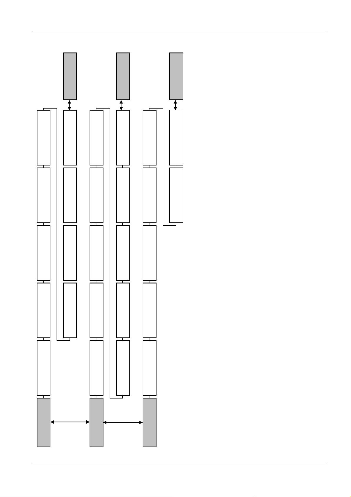
Programming flow chart
MAIN MENU
ENGLISHOFF
START VALUE LANGUAGE
xxxxx:xx
AUTO - START OPERAT. TIME
4.1
xx:xxxx-xx-20xx OFF
xxxxx:xx
MOTOR HOURS
enabled
23.2
SUBMENU
4TH ERROR 5TH ERROR
3RD ERROR2ND ERROR
STATUS
NO ERROR NO ERROR
CURR.INVERTER VOLT.INVERTER
SUBMENU
VER. INVERTER
OUTPUT FREQ
46 47 40
DIAGNOSTICS
xx
xx.x Hz
x: X:
23.3
DATE TIME
6789 0
3,5 bar 3,5 bar 3,5 bar 4.1 5.1
XYLEM
MAIN MENU REQUIRED VAL EFF REQ VAL
0 ITT xx.x Hz 2345
SUBMENU SELECT DEVICE ENABLE DEVICESTATUS UNITS STATUS DEVICE
20 21 22 23 24 25
* 01 * running
00000000
STATUS
NO ERROR NO ERROR
NO ERROR
1ST ERROR
26 27 28 29 30 20
26.1
20.1
SEL. INVERTER TEMP.INVERTERSUBMENU PROD. DATE
40 41 42 43 44 45
x: x: x:
xx-xx-xxxx * 01 * xx % xxx Vxx % xx C°
DIAGNOSTICS
40.1
100
 Loading...