

Page 1

Installation & Operating Manual
Please read this manual carefully before attempting to install, operate or maintain the product described. Failure to
comply with the information provided in this manual could result in personal injury and/or property damage. Retain
this manual for future reference.
Laing Thermotech
Instruction Manual
SM-303
SM-909-14(18,26)
SM-1212/1252-21(26)
Plastic Housing SM-303 Stainless Housing SM-909/1212
Plastic Housing SM-909/1212
Seal-less Centrifugal Canned Motor Pumps
Plastic and Stainless Housing 60 Cycle
INSTALLER: PLEASE LEAVE THIS MANUAL FOR THE OWNER’S USE.
Description
Laing centrifugal pumps are designed for circulation and transfer of a variety of fluids compatible with
their materials of construction limited to maximum fluid temperatures and maximum line pressures as
indicated below. Unique leakproof integrated motor/pump design eliminates the need for
conventional mechanical seals or other shaft sealing devices. They are self lubricating and require no
external lubrication.
Unpacking
When unpacking the unit inspect carefully for any damage that may have occurred during transit.
Check for loose, damaged, or missing parts (see pump exploded view and replacement parts list). Do
not attempt to assemble or operate pump if any parts are missing or damaged.
General Safety Information
1. Know the pump application, limitations and potential hazards.
2. Make certain that the power source conforms to the requirements of your equipment.
Page 2

3. Disconnect power before servicing. If the power disconnect is out of sight, lock in the open
position and tag it to prevent unexpected application of power. Failure to do so could result in fatal
electric shock!
4. Release all pressure within the system before servicing any component.
5. Drain liquids from the system before servicing.
6. Personal Safety
a. Wear safety glasses at all times when working with pumps.
b. Wear a face shield and proper apparel when pumping hazardous chemicals.
c. Keep work area clean, uncluttered, and properly lighted. Replace all unused tools and
equipment.
d. Keep visitors at a safe distance from the work area.
e. Make workshop childproof with padlocks, master switches and by removing starter keys.
7. The motor is designed to be used in a clean dry location with access to an adequate supply of cooling
air. Ambient temperature around the motor should not exceed 104ºF (40ºC). For outdoor installations
motor must be protected by a cover that does not block airflow to and around the motor. This unit is
not able to be submersed in water.
8. When wiring an electrically driven pump follow all electrical and safety codes, as well as the most
recent United States National Electrical Code (NEC) and the Occupational Safety and Health Act
(OSHA).
9. Single phase motors: All units are supplied with 115 volt, single phase motors (unless otherwise
noted) and provided with a 6 foot 3-wire flexible cord with 3-prong grounded plug suitable for a
standard grounded type 115 volt receptacle. Where a 2-prong wall receptacle is encountered, it must
be replaced with a properly grounded 3-prong receptacle installed in accordance with the National
Electrical Code, local codes and ordinances. To ensure a proper ground, the grounding means must be
tested by a qualified electrican.
10. Use only 3-wire extension cords that have 3-prong grounding type plugs and 3-pole receptacles
that accept the equipment plug.
11. All wiring should be performed by a qualified electrician.
12. Protect electrical cord from sharp objects, hot surfaces, oil, and chemicals. Avoid kinking the cord.
Replace or repair damaged or worn cords immediately.
Specifications 115v or 230v, 60 cycle, 1 phase (see pump nameplate)
Model No. HP Pump Inlet/Outlet Max. Max. Line Weight (lbs.)
Housing Fluid Temp. (F) Pressure
SM-303 1/150 N 1/2” or 3/4” Hose barb 140º 50 PSI 2.0
SM-303 1/150 N 1/2” Male NPT 140º 50 PSI 2.0
SM-909-14 1/50 N 3/4” Hose barb 140º 50 PSI 4.2
SM-909-14 1/50 N 3/4” Male NPT 140º 50 PSI 4.2
SM-909-14 1/50 316 SS 3/4” Female NPT 230º 150 PSI 5.5
SM-909-18 1/20 N 3/4” Hose barb 140º 50 PSI 4.2
SM-909-18 1/20 N 3/4” Male NPT 140º 50 PSI 4.2
SM-909-18 1/20 316 SS 3/4” Female NPT 230º 150 PSI 5.5
SM-909-26 1/20 N 3/4” Hose barb 140º 50 PSI 4.2
SM-909-26 1/20 N 3/4” Male NPT 140º 50 PSI 4.2
SM-909-26 1/24 316 SS 3/4” Female NPT 230º 150 PSI 5.5
SM-1212-26 1/15 N 3/4” Hose barb 140º 50 PSI 4.2
SM-1212-26 1/15 N 3/4” Male NPT 140º 50 PSI 4.2
SM-1212-26 1/15 316 SS 3/4” Female NPT 230º 150 PSI 5.5
SM-1212-21 1/15 N 1” Hose barb 140º 50 PSI 4.2
N = Polypropylene Housing
Materials of Construction (Wetted Parts)
Part Plastic Housing Models Stainless Housing Models
Pump Housing Polypropylene 316 Stainless Steel
“O” Ring EPDM or Viton EPDM or Viton
Impeller Polypropylene Noryl (Polypropylene)
Bearing Carbon Graphite/Ceramic Carbon Graphite/Ceramic
All Other Wetted Parts 316 Stainless Steel 316 Stainless Steel
2
Page 3
Installation
In order to safely use this product, familiarize yourself with this pump and also with the liquid
(chemical, etc.) that is going to be pumped through the unit. This pump is not suitable for many
liquids.
For installations where property damage might result from an inoperative or leaking pump due to
power outages, discharge line blockage, or any other reason, a backup system(s) should be used.
Failure to follow any warning can result in personal injury and/or property damage.
1. Locate pump as close to the fluid source as possible, thus making the suction line as short and
direct as possible.
2. Attach piping suction line to suction inlet and piping discharge line to discharge outlet. Avoid using
looped section of pipe or fittings which might permit air to compromise airtight pipe connections.
IMPORTANT: If plastic or fabric hose is used for the suction piping it should be of a reinforced type so
as not to collapse under suction.
3. Support the piping independently of the pump.
4. Laing circulators are lubricated by the pumped fluid. How they are mounted and the condition of
the water in the system are important. THOROUGHLY CLEAN and FLUSH the system before installing
the circulator. If the fluid contains a high level of dissolved solids such as dirt, sediment, or products of
corrosion, a strainer and/or filter should be installed at least 12” before the inlet to the circulator.
Electrical
These instructions must be followed to reduce risk of electrical shock. All work should be performed
by a qualified electrician and in accordance with the current national and local electrical codes and
regulations. Consult the nameplate for electrical data. The motor is impedance protected.
Make certain that a properly sized circuit is available. Wire size should be based on the current
carrying (amp) capacity of the conductor. The circulator must be grounded in accordance with the
current national and local codes. Ground wire should be copper with current capacity at least equal
to that of the wire carrying power to the circulator. Observe all minimum code requirements for your
jurisdiction.
For circulators supplied with a power cord, the current carrying capacity of the cord is suitable for
proper operation. Make certain the receptacle is properly configured and in good working order.
Check to make certain that the circuit is properly sized for the load.
Circulators intended for hard wire applications are supplied with 6” pigtails of proper current carrying
capacity and with a knockout in the motor end cap. Leads suitable for at least 194ºF (90ºC) should be
used and connected to the pigtails or directly to the terminals as indicated in the electrical
compartment. Grounding wire should also be suitable for 194ºF (90ºC) and should be connected to
the grounding terminal as indicated in the electrical compartment.
Isolation valves are recommended for both sides of the circulator. Valves should be positioned to avoid
leakage onto the motor and electrical compartment. All elbows, tees, and sharp bends in the piping
should be installed sufficiently upstream or downstream of the suction and discharge ports. Avoid
welding or soldering close to the circulator, which could cause damage to the unit.
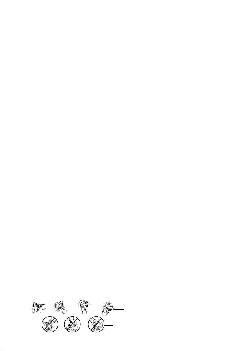
Mounting
For installation purposes the arrows on the side of the pump housing indicate the direction of water
flow through the circulator. Check to make sure the circulator is adequately supported and that
neither the circulator nor the piping is severely stressed. Install the circulator at a point closest to the
highest static pressure point, but above the absolute lowest point in the system to avoid dirt and
sediment build-up. If required by application and code, install a safety relief valve to protect against
over temperature and pressure. Do not mount with the motor above the impeller. This can cause the
circulator to run dry leading to premature failure of the circulator which voids the warranty. Refer to
the figures below for proper orientation before installing the circulator.
Correct Installation
Improper Installation - Do not mount in these orientations
3
Page 4

Wiring Diagrams
Black
Brown
Yellow
Red
Pump
Taped End
Black White
115v or 230v line In
Orange
Orange
Capacitor
C
B
A
I
Brown
Black
White
Black
or White
Black or Red
Blue
Green
TCO
Ground Lug
TCO Settings
Open 212ºF + 10ºF
Close 176ºF +- 10ºF
Capacitor
Fig. 3 - SM-303 models
Fig. 4 - SM-909 and SM-1212 models
Operation
1. Completely fill the system before operating the circulator. Do not start the circulator until the
system has been filled. Make sure the isolation valves are fully open and that there is water in the
circulator.
2. Purge air from the system prior to operating the circulator. These two steps are very important. The
circulator should never be allowed to run dry. This can severely damage the circulator and will void the
warranty.
3. Operate the circulator for approximately 10 minutes to purge any remaining air in the system. It
may be necessary to open a discharge valve, port
and/or fixture to ensure that the air
has been purged.
The circulator should be running quietly. If a “gurgling” noise is present it may mean there is still air in
the system. Turning the circulator on and off several times will generally clear the remaining air. If this
“gurgling” noise persists, recheck the system and re-purge the air. System and circulator should now
operate quietly and efficiently.
4. Dry Run Internal Thermostat: All plastic housing model pumps are provided as standard with an
integral dry run protection thermostat that turns pump off when pump runs dry (thermostat off at
212ºF + 10ºF). If left unattended, the thermostat will automatically reset within a relatively short
amount of time when the unit cools down, thereby allowing the pump to again begin operation (at
176ºF+ 13ºF). Depending on the system conditions, many times one or two of these off/on cycles will
correct an air bound dry run condition by itself with no harm done to the pump, thereby allowing
continued trouble free operation. However, if the off/on cycling persists then measures should be taken
to correct the problems in the circulation system causing the on/off cycling. Stainless housing pumps
are not provided with a dry run thermostat.
Maintenance
1. Since the rotor/impeller unit (see exploded views) is the only moving part, its replacement and/or the
replacement of the motor is simple to accomplish.
2. After the power has been disconnected remove the screws holding the pump housing to the motor
(in the case of model SM-909 and SM-1212 units) or using a counter clockwise motion remove the
screw ring housing to motor connection on model SM-303 units.
3. Remove the “O” ring from the pump housing.
4. Remove and replace the rotor. Check to make sure that the ceramic bearing on the motor is intact
and is not chipped or otherwise damaged.
5. Replace the “O” ring with a new one and reverse the disassembly procedure to reassemble the
pump.
6. Since these units are self lubricated by the pumped fluid, they never need external lubrication.
7. Pump should be drained when subjected to freezing temperatures.
8. If provided, the suction line strainer should be cleaned at regular intervals.
Warranty
Laing recirculation pumps are warranted against defects in materials and workmanship for 24 months from
the date of manufacture (see mfg. date label on pump) or twelve (12) months from date of user purchase,
with proof of purchase, whichever is later. In order to receive warranty considerations, the product must be
returned prepaid to the company from which it was originally purchased. If the pump is found defective,
the pump will be replaced or in the case of wholesale customers, appropriate purchase credit will be issued.
Prior to returning any defective pump to Laing for warranty consideration, contact the Laing factory for
an RMA tracking number. Any claim for consequential damages resulting from a pump malfunction is not
covered by the Laing warranty. Additional warranty details are available on request.
4
Page 5

Replacement Parts
Please provide the following information:
• Model number
• Serial number (if any)
• Part description
SM-303-N
SM-909-N and SM-1212-N
SM-909-T and SM-1212-T
SM-909-S
SM-1212-S
Pump Housing
"O" Ring
Rotor/Impeller
Assembly
Motor Assembly
Screw Ring
Trouble Shooting Chart
Symptom Possible Causes Corrective Action
Motor will not start or run 1. Improperly wired 1. Check motor wiring diagram
2. Blown fuse or open circuit breaker 2. Replace fuse or circuit breaker after
reason for overload has been corrected
3. Loose or broke wiring 3. Tighten connections, repair wiring
4. Foreign object in impeller 4. Disassemble pump, remove object
5. Motor shorted out 5. Replace motor
6. Dry run cutout has opened circuit 6. Allow unit to cool, restart after
reason for cutout has been
determined and corrected
Pump will not prime 1. Leak, obstruction, or kink in suction 1. Repair as necessary
line
2. Suction line closed 2. Open
3. Pump is worn 3. Replace parts
Little or no discharge 1. Housing not filled with water 1. Properly prime housing
2. Suction piping too small 2. Increase to pump inlet size or one
size larger
3. Total head too high 3. Reduce discharge head
4. Impeller plugged 4. Disassemble pump and clean impeller
5. Pump not running 5. Check motor operation
Noisy pump operation 1. Air trapped in housing 1. Check pump prime, also turn pump
on and off several times to bump
air pocket out of pump
2. Rotor bearing worn 2. Replace rotor assembly
3. Debris in housing 3. Disassemble pump and remove debris
Safety Requirements
Mechanical Safety
WARNING: - Excessive System Pressure Hazard - The maximum working pressure of the
pump is listed on the nameplate - Do Not Exceed This Pressure. Failure to follow these
instructions could result in serious personal injury, death and/or property damage.
WARNING: - Excessive Pressure Hazard Volumetric Expansion - The heating of water and
other fluids causes volumetric expansion. The associated forces may cause failure of system
components and the release of high temperature fluids. This can be prevented by installing
properly sized and located compression tanks and pressure relief valves. Failure to follow
these instructions could result in serious personal injury, death and/or property damage.
5
Page 6
Thermal Safety
WARNING: - Extreme Temperature Hazard - If the pump, motor or piping are operating at
extremely high or low temperature, guarding or insulation is required. Failure to follow these
instructions could result in serious personal injury, death and/or property damage.
Electrical Safety
WARNING: - Electrical Shock Hazard - Electrical connections are to be made by a qualified
electrician in accordance with all applicable codes, ordinances and good practices. Failure
to follow these instructions could result in serious personal injury, death and/or property
damage.
WARNING: - Electrical Grounding Hazard - Adequate electrical grounding is required for
the safe operation of Laing Pumps. Ground the pump back to the service using a copper
conductor at least the size of the circuit connectors supplying the pump. Connect the ground
wire to the ground terminal in the wiring compartment. Failure to follow these instructions
could result in serious personal injury, death and/or property damage.
WARNING: - Risk of Electric Shock - Do not install this pump in swimming pool or marine
areas. Failure to follow these instructions could result in serious personal injury, death and/or
property damage.
Removal of Pump From Existing System For Replacement
WARNING: - Electrical Shock Hazard - Disconnect and lockout the power before
servicing. Failure to follow these instructions could result in serious personal injury, death
and/or property damage.
1. Close the valves on the suction and discharge sides of the pump. (if no valves have been installed, it
may be necessary to drain the system.)
2. Disconnect the electrical supply lines to the pump.
WARNING: - Hot Water Hazard - Before draining the system, allow water to cool to at least
100F, open the drain valve (take precautions against water damage) and leave the drain valve
open until servicing is complete. Failure to follow these instructions could result in serious
personal injury, death and/or property damage.
WARNING: - Electrical Shock Hazard - Be certain the electrical power is not present at the
motor leads before continuing. Failure to follow these instructions could result in serious
personal injury, death and/or property damage.
WARNING: - High Pressure Hazard - Pressure may be present in the pump body. This
pressure can be relieved by loosening the flange bolts and shifting the pump assembly
slightly to allow the pressurized water to escape. Failure to follow these instructions could
result in serious personal injury and death.
U.L. Caution
This pump has been tested using water only. Its suitability for use with liquids other than
water is the end user’s responsibility.
Copyright © 2009 ITT Corporation,
Printed in the U.S.A 1-10 IM-06
THE ITT ENGINEERED BLOCKS
SYMBOL AND ENGINEERED FOR LIFE
ARE REGISTERED TRADEMARKS OF
ITT MANUFACTURING
ENTERPRISES, INC.
ITT
3878 S. Willow, Suite 104
Fresno, CA 93725
Tel: (559) 265-4730 (800) 554-6853
Fax: (559) 265-4740 (800) 453-7523
www.lainginc.com
6
 Loading...