

Page 1
REPAIR STACK
IM235
This repair stack instruction sheet MUST be used in
conjunction with Goulds Water Technology Installation,
Operation and Maintenance manual for the Model e-SV.
Contact your local Goulds Water Technology distributor
or the factory for a replacement manual if needed.
Before placing repaired pump back on line,
CAREFULLY examine removed components and
entire pump system for indications of the cause of
the component failure and possible corrective action.
Massive component failure may indicate that the
pumping system is not adequately protected from
deadheading, running beyond maximum flow, water
hammer, abrasive particulate, etc.
Model e-SV
Vertical, Multi-Stage Pumps
REPAIR STACK INSTALLATION INSTRUCTIONS
Page 2
DANGER
WARNING
CAUTION
SAFETY INSTRUCTIONS
TO AVOID SERIOUS OR FATAL PERSONAL
INJURY OR MAJOR PROPERTY DAMAGE, READ
AND FOLLOW ALL SAFETY INSTRUCTIONS IN
MANUAL AND ON PUMP.
This is a SAFETY ALERT SYMBOL.
When you see this symbol on the pump or
in the manual, look for one of the following signal words and be alert to the potential for personal injury or property damage.
Warns of hazards that WILL cause serious
personal injury, death or major property
damage.
Warns of hazards that CAN cause serious
personal injury, death or major property
damage.
Warns of hazards that CAN cause personal
injury or property damage.
NOTICE: INDICATES SPECIAL INSTRUCTIONS
WHICH ARE VERY IMPORTANT AND
MUST BE FOLLOWED.
THOROUGHLY REVIEW ALL INSTRUCTIONS
AND WARNINGS PRIOR TO PERFORMING ANY
WORK ON THIS PUMP.
MAINTAIN ALL SAFETY DECALS.
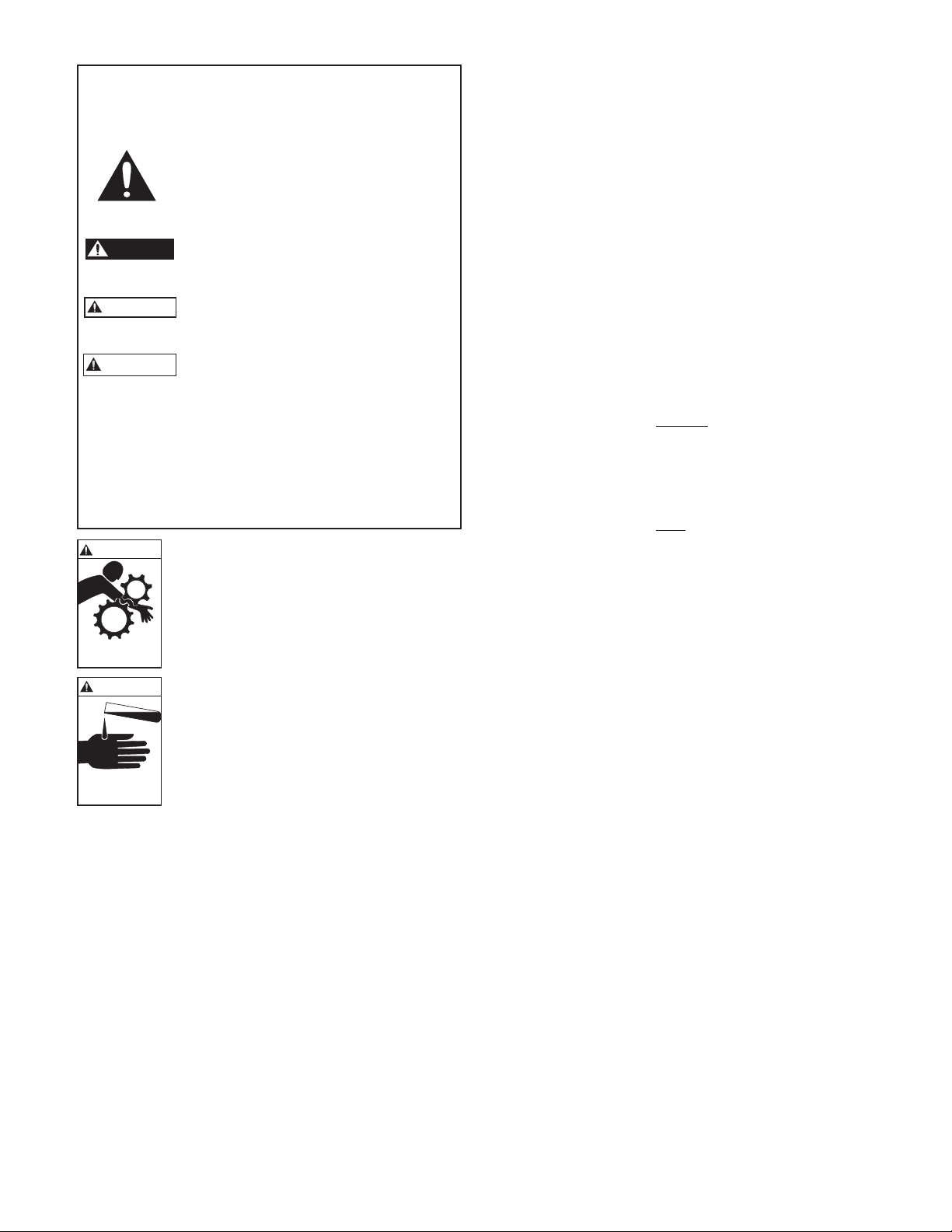
WARNING
Hazardous machinery
can cause personal
injury or death.
WARNING
FAILURE TO DISCONNECT AND
LOCKOUT ELECTRICAL POWER BEFORE ATTEMPTING MAINTENANCE
CAN CAUSE SEVERE PERSONAL INJURY.
IF PUMPING HAZARDOUS OR TOXIC
FLUIDS, SYSTEM MUST BE FLUSHED
PRIOR TO PERFORMING SERVICE.
PUMP STACK REMOVAL
1. Close all necessary suction and discharge valves.
2. Drain the liquid from the pump by removing the lower
drain plug and the upper vent plug.
3. Remove the coupling guards, the 4 coupling hex cap
screws, the coupling and coupling drive pin.
4. Remove the 4 motor hex cap screws. *On 33-125SV
units with motor frames 213TC and larger and
1-22SV units with motor frames 280TC and larger,
remove the 4 motor adapter flange hex cap screws.
5. With an adequately sized crane, carefully remove the
motor. DO NOT rest the motor on the motor shaft.
6. Remove Seal Gland or Cartridge Seal
• For 1-22SV units, remove the 4 socket head cap
screws to lift and remove the seal gland.
• For 33-125SV units without cartridge seal;
1. Remove the 4 socket head cap screws.
2. Lift and remove the seal gland. If seal gland
does not lift by hand, use the two tapped holes
provided to loosen and lift the gland for removal.
• For 33-125SV units with cartridge seal;
1. Loosen the 4 set-screws located around the ID of
the pump shaft.
2. Remove the 4 socket head cap screws.
3. Remove the cartridge seal using the two tapped
holes provided on the gland of the cartridge seal
by threading two of the hex cap screws into these
holes and evenly tightening these screws..
4. Once loosened, lift and remove the cartridge seal.
7. Remove the 4 tie rod nuts and washers.
Hazardous fluids can
cause personal injury
or property damage.
8. Remove Motor Adapter / Motor adapter assembly and
upper seal plate
• For 1-22SV units lift the motor adapter to remove.
*Note that the upper seal plate may remove with the
motor adapter when lifting. If the upper seal plate
remains on the pump casing, lift to remove.
• For 33-125SV units, lift the motor adapter assembly
(motor adapter and top seal plate). A crane may be
required to safely lift the motor adapter assembly.
9. Remove the pump stack, grasp the pump shaft, rock
side to side to free the stack, then lift vertically. If the
first stage bowl remained in the pump body, CARE-
FULLY pry up the bowl and remove.
2
Page 3

REPAIR STACK INSTALLATION
1. Inspect and clean the inside of the pump body, removing any debris.
2. Remove repair stack from packaging, inspect for
damage and clean, removing any tape used to hold
components together.
3. Grasp shaft of repair stack and lower into the pump
body. Center the stack within the pump body until
the first stage seats in the bottom. Push down on
stack to lock in place.
4. Replace O-ring in top groove in casing.
5. Re-install the upper seal plate and motor adapter
• For 1-22SV units place the upper seal plate squarely
on top of the pump casing and press down firmly.
The seal plate should seat firmly and the o-ring
should remain in the casing groove. Once upper
seal plate is installed the motor adapter can be
placed on top of the assembly and aligned as originally installed.
• For 33-125SV units, lift the motor adapter assembly (motor adapter and top seal plate) and
place squarely on top of the pump casing, aligned
as originally installed. A crane may be required to
safely lift the motor adapter assembly.
• For 33-125SV units without cartridge seal;
1. Remove the used stationary seal seat from the
seal gland.
2. With a clean cloth wipe the seal bore and inspect
for damage; replace seal gland if damaged.
3. Insert the new stationary seal seat into the seal
bore of the seal gland with the seal face out. DO
NOT scratch or damage the seal face. Ensure
that the seal is seated firmly and squarely inside
the seal bore. With a clean lint-free cloth or alcohol swab wipe the seal face clean of all lubricant
or debris. DO NOT use grease or heavy lubricants to install seal, as these materials can cause
the seal to leak.
4. Rotate the rotary portion of the mechanical seal
on the pump shaft until it “locks” and you are
unable to turn freely. If you are unable to turn
initially, the seal is seated properly.
5. Replace o-ring on seal gland.
6. Install the seal gland onto the pump shaft, seating the plate fully and squarely.
7. Re-install the 4 socket head cap screws (see
“Torque Values” for appropriate tightening
torque). The screws should be tightened in small
increments in a diagonal pattern to ensure the
seal gland seats properly.
6. Reinstall Tie Rods, Nuts, and Washers (see “Torque
Values” for appropriate tightening torque). The tierod nuts should be tightened in small increments in a
diagonal pattern to ensure it seats properly. Pay close
attention to ensure that the casing o-ring remains in
the casing groove.
7. Reinstall Seal Gland or Cartridge Seal
• For 1-22SV units, remove the used stationary seal
face from the seal gland.
1. Remove the used stationary seal seat from the
seal gland.
2. With a clean cloth wipe the seal bore and inspect
for damage; replace seal gland if damaged.
3. Insert the new stationary seal seat into the seal
bore of the seal gland with the seal face out. DO
NOT scratch or damage the seal face. Ensure
that the seal is seated firmly and squarely inside
the seal bore. With a clean lint-free cloth or alcohol swab wipe the seal face clean of all lubricant
or debris. DO NOT use grease or heavy lubricants to install seal, as these materials can cause
the seal to leak.
4. Replace o-ring on seal gland.
5. Install the rotating portion of the seal onto the
pump shaft, seating the plate fully and squarely.
6. Re-install the 4 socket head cap screws (see
“Torque Values” for appropriate tightening
torque). The screws should be tightened in small
increments in a diagonal pattern to ensure the
seal gland seats properly.
• For 33-125SV units with cartridge seal;
1. Replace the o-ring on the cartridge seal.
2. Slide the cartridge seal assembly along the pump
shaft into position and alignment with bolt
holes. Seat the cartridge seal squarely and firmly.
3. Re-install the 4 socket head cap screws (see
“Torque Values” for appropriate tightening
torque). The screws should be tightened in small
increments in a diagonal pattern to ensure the
seal gland seats properly.
8. Reinstall the coupling pin and locate the spacer shim
on the shaft, resting on the seal gland or cartridge
seal. If the shim is not available, a 5mm shim can be
used.
9. Lower the motor slowly onto the motor adapter and
align the motor shaft with the coupling and motor
mounting holes. Reinstall the 4 motor hex cap screws
(see "Torque Values" for appropriate tightening
torque) to secure motor to motor adapter.
10. Reinstall the coupling halves evenly to maintain a
consistent gap on either side of the coupling halves.
The coupling halves should not touch. Torque the
coupling bolts to the appropriate values defined in
“Torque Values”.
11. Remove the spacer shim and save for future use.
12. FOR 33-125SV PUMPS WITH CARTRIDGE SEAL
ONLY; tighten the 4 set screws on the shaft collar.
3
Page 4

TORQUE VALUES
HP Motor Bolt Adapter Flange
Coupling
1-5SV 10-22SV 33-125SV
0.5-7.5 HP 20 lbs ft (27 N m) — 15 lbs ft (20 N m) 40 lbs ft (54 N m) 37 lbs ft (50 N m)
10-75 HP 45 lbs ft (61 N m) 48 lbs ft (65 N m)* 15 lbs ft (20 N m) 40 lbs ft (54 N m) 48 lbs ft (65 N m)
*213TC and 215TC Adapter Flange use 30 lbs ft (40 N m)
Pump Size Tie Rod Nuts Vent / Drain Plug
1-5SV 22 lbs ft (30 N m) 15 lbs ft (20 N m)
10-22SV 37 lbs ft (50 N m) 15 lbs ft (20 N m)
33-125SV 44 lbs ft (60 N m) 29 lbs ft (40 N m)
Seal Gland [lbs ft (N m)]
1-22SV 33-125SV
18 lbs ft (25 N m) 37lbs ft (50 N m)
GOULDS WATER TECHNOLOGY LIMITED WARRANTY
This warranty applies to all water systems pumps manufactured by Goulds Water Technology.
Any part or parts found to be defective within the warranty period shall be replaced at no charge to the dealer during the warranty period. The warranty period shall exist for
a period of twelve (12) months from date of installation or eighteen (18) months from date of manufacture, whichever period is shorter.
A dealer who believes that a warranty claim exists must contact the authorized Goulds Water Technology distributor from whom the pump was purchased and furnish
complete details regarding the claim. The distributor is authorized to adjust any warranty claims utilizing the Goulds Water Technology Customer Service Department.
The warranty excludes:
(a) Labor, transportation and related costs incurred by the dealer;
(b) Reinstallation costs of repaired equipment;
(c) Reinstallation costs of replacement equipment;
(d) Consequential damages of any kind; and,
(e) Reimbursement for loss caused by interruption of service.
For purposes of this warranty, the following terms have these definitions:
(1) “Distributor” means any individual, partnership, corporation, association, or other legal relationship that stands between Goulds Water Technology and the dealer in
purchases, consignments or contracts for sale of the subject pumps.
(2) “Dealer” means any individual, partnership, corporation, association, or other legal relationship which engages in the business of selling or leasing pumps to customers.
(3) “Customer” means any entity who buys or leases the subject pumps from a dealer. The “customer” may mean an individual, partnership, corporation, limited liability
company, association or other legal entity which may engage in any type of business.
THIS WARRANTY EXTENDS TO THE DEALER ONLY.
Xylem, Inc.
2881 East Bayard Street Ext., Suite A
Seneca Falls, NY 13148
Phone: (800) 453-6777
Fax: (888) 322-5877
www.xyleminc.com/brands/gouldswatertechnology
Goulds is a registered trademark of Goulds Pumps, Inc. and is used under license.
© 2012 Xylem Inc. IM235 Revision Number 1 July 2012
 Loading...