

Page 1

End Suction Pump e-NSC Series
Models e-NSC, e-NSCF, e-NSCC
Applicare qui il codice a barre
Apply the adhesive bar code nameplate here
it Manuale di installazione, uso e manutenzione de Montage-, Betriebs- und Wartungshandbuch
en Installation, Operation, and Maintenance Manual tr Montaj, Çalıştırma ve Bakım Kılavuzu
fr Manuel d'installation, d'utilisation et d'entretien ru Руководство по установке, эксплуатации и техническому
обслуживанию
771073500
Page 2

it - Istruzioni originali
Manuale di installazione, uso e manutenzione...............................3
1 Introduzione e sicurezza............................................................... 3
2 Movimentazione e stoccaggio.......................................................4
3 Descrizione del prodotto............................................................... 4
4 Installazione.................................................................................. 6
5 Messa in funzione, avvio, funzionamento e spegnimento.............9
6 Manutenzione................................................................................9
7 Risoluzione dei problemi.............................................................10
en - Translation of the original instructions
Installation, Operation, and Maintenance Manual........................ 12
1 Introduction and Safety............................................................... 12
2 Transportation and Storage.........................................................13
3 Product Description.....................................................................13
4 Installation...................................................................................15
5 Commissioning, Startup, Operation, and Shutdown................... 18
6 Maintenance................................................................................18
7 Troubleshooting...........................................................................19
fr - Traduction des instructions d'origine
Manuel d'installation, d'utilisation et d'entretien..........................21
1 Introduction et sécurité................................................................21
2 Transport et stockage..................................................................22
3 Descriptif du produit.................................................................... 22
4 Installation...................................................................................24
5 Contrôle de réception, Démarrage, Fonctionnement et
Extinction.................................................................................. 27
6 Entretien......................................................................................28
7 Recherche des pannes............................................................... 28
ru - Перевод с оригинала
Руководство по установке, эксплуатации и
техническому обслуживанию..................................................50
1 Подготовка и техника безопасности.........................................50
2 Транспортирование и хранение............................................... 51
3 Описание изделия.....................................................................51
4 Установка...................................................................................53
5 Ввод в эксплуатацию, запуск, эксплуатация и останов..........56
6 Техническое обслуживание......................................................57
7 Устранение.................................................................................57
Appendice tecnica • Technical appendix • Technischer
Anhang • Teknik ek • Техническое приложение..................... 60
de - Übersetzung vom Original
Montage-, Betriebs- und Wartungshandbuch...............................31
1 Einführung und Sicherheit...........................................................31
2 Transport- und Lagerung.............................................................32
3 Produktbeschreibung.................................................................. 32
4 Montage...................................................................................... 34
5 Inbetriebnahme, Anfahren, Betrieb und Abfahren.......................37
6 Wartung.......................................................................................38
7 Fehlerbehebung..........................................................................38
tr - Orijinal metnin çevirisidir
Montaj, Çalıştırma ve Bakım Kılavuzu........................................... 41
1 Giriş ve Güvenlik.........................................................................41
2 Taşıma ve Depolama.................................................................. 42
3 Ürün Açıklaması..........................................................................42
4 Montaj......................................................................................... 44
5 Devreye alma, Başlatma, Çalıştırma ve Kapatma...................... 46
6 Bakım..........................................................................................47
7 Sorun Giderme............................................................................48
2 e-NSC Installation, Operation, and Maintenance Manual
Page 3
it - Istruzioni originali
1 Introduzione e sicurezza
1.1 Introduzione
Finalità di questo manuale
Questo manuale ha lo scopo di fornire le informazioni necessarie per
effettuare correttamente le seguenti operazioni:
• Installazione
• Funzionamento
• Manutenzione
ATTENZIONE:
Prima dell'installazione e dell'utilizzo del prodotto, leggere attentamente questo manuale. L'uso improprio del prodotto
può causare lesioni personali e danni alle cose e può invalidare la garanzia.
NOTA BENE:
Conservare questo manuale per future consultazioni e tenerlo sempre
disponibile e a portata di mano nel luogo in cui è installata l'unità.
1.1.1 Utenti inesperti
AVVERTENZA:
L'utilizzo di questo prodotto è riservato esclusivamente a
personale qualificato.
Attenersi alle seguenti precauzioni:
• Persone diversamente abili possono utilizzare il prodotto esclusivamente con la supervisione di un professionista o se sono state
adeguatamente formate da un professionista.
• I bambini devono essere sorvegliati per sincerarsi che non giochino con la pompa o nelle sue vicinanze.
1.2 Terminologia e simboli di sicurezza
Informazioni sui messaggi di sicurezza
È molto importante leggere, comprendere e seguire le indicazioni riportate nei messaggi e nelle normative di sicurezza prima di maneggiare il prodotto. Tali messaggi e normative sono pubblicati per evitare
i seguenti rischi:
• Lesioni personali e problemi di salute
• Danni al prodotto
• Malfunzionamento del prodotto
Livelli di pericolo
Livello di pericolo
PERICOLO:
AVVERTENZA:
ATTENZIONE:
NOTA BENE:
Categorie di pericolo
Le categorie di pericolo possono corrispondere ai livelli di pericolo o, in
alternativa, dei simboli specifici possono sostituire i normali simboli di
livello di pericolo.
I pericoli elettrici sono indicati dal seguente simbolo specifico:
PERICOLO ELETTRICO:
Di seguito si elencano esempi di altre possibili categorie. Queste rientrano nei normali livelli di pericolo e possono utilizzare simboli complementari:
• Pericolo di schiacciamento
Indicazione
Una situazione di pericolo che, se
non evitata, causerà morte o gravi
lesioni personali.
Una situazione di pericolo che, se
non evitata, può causare morte o
gravi lesioni personali.
Una situazione di pericolo che, se
non evitata, potrebbe determinare
lesioni di entità lieve o media.
• Una situazione potenzialmente pericolosa che, se
non evitata, potrebbe determinare condizioni non desiderabili
• Un'azione che non comporta
lesioni personali
• Pericolo di tagli
• Pericolo di arco elettrico
Pericolo di superficie surriscaldata
I pericoli di superficie calda sono indicati da un simbolo specifico che
sostituisce i simboli tipici di livello di pericolo:
ATTENZIONE:
Descrizione dei simboli per l'utilizzatore e l'installatore
Informazioni specifiche per il personale responsabile
dell'installazione del prodotto nel sistema (impianto
idraulico e/o elettrico) o della manutenzione del prodotto.
Informazioni specifiche per gli utilizzatori del prodotto.
Istruzioni
Le istruzioni e gli avvertimenti forniti nel presente manuale riguardano
la versione di serie, come descritto nella documentazione di vendita.
Eventuali versioni speciali possono essere fornite di fogli di istruzione
supplementari. Per eventuali modifiche o caratteristiche delle versioni
speciali, fare riferimento alla documentazione contrattuale di vendita.
Per istruzioni, situazioni o eventi non contemplati nel presente manuale o nella documentazione di vendita, contattare il Servizio assistenza
Lowara più vicino.
1.3 Smaltimento dell'imballo e del prodotto
Rispettare le leggi e norme locali vigenti per lo smaltimento differenziato dei rifiuti.
1.4 Garanzia
Per informazioni sulla garanzia vedere la documentazione contrattuale
di vendita.
1.5 Parti di ricambio
AVVERTENZA:
Utilizzare solo parti di ricambio originali per sostituire eventuali componenti usurati o guasti. L'uso di parti di ricambio
inadeguate può causare malfunzionamenti, danni e lesioni
personali nonché determinare la perdita di validità della garanzia.
ATTENZIONE:
Precisare sempre l'esatto tipo e codice del prodotto qualora
sia necessario richiedere informazioni tecniche o parti di ricambio al Servizio di Vendita ed Assistenza.
Per ulteriori informazioni sulle parti di ricambio della pompa, vedere
gura 1 , Figura 2 , Figura 3 o Figura 4
Fi-
1.6 DICHIARAZIONE CE DI CONFORMITÀ
XYLEM SERVICE ITALIA S.R.L., CON SEDE IN VIA VITTORIO LOMBARDI 14 - 36075 MONTECCHIO MAGGIORE VI - ITALIA, DICHIARA
CHE IL PRODOTTO SEGUENTE:
ELETTROPOMPA (VEDERE ADESIVO SULLA PRIMA PAGINA)
È CONFORME ALLE DISPOSIZIONI DELLE SEGUENTI DIRETTIVE
EUROPEE:
• DIRETTIVA MACCHINE: 2006/42/CE (IL FILE TECNICO È DISPONIBILE PRESSO XYLEM SERVICE ITALIA S.R.L.).
• COMPATIBILITÀ ELETTROMAGNETICA 2004/108/CE
• PROGETTAZIONE ECOCOMPATIBILE 2009/125/CE, NORMATIVA (CE) N. 547/2012, NORMATIVA (CE) 640/2009 (3 ~, 50 Hz,
PN≥ 0,75 kW) SE CON LIVELLO DI EFFICIENZA IE2 o IE3
E ALLE SEGUENTI NORME TECNICHE
• EN 809, EN 60335-1, EN 60335-2-41, EN 62233
• EN 61000-6-1:2007, EN 61000-6-3:2007
• EN 60034–30
• EN 953 :1997+A1:2009
• EN ISO 12100 :2010
• EN 60204-1 :2006/A1:2009
POMPA (VEDERE ADESIVO SU PRIMA PAGINA)
e-NSC Installation, Operation, and Maintenance Manual 3
Page 4
it - Istruzioni originali
È CONFORME ALLE DISPOSIZIONI DELLE SEGUENTI DIRETTIVE
EUROPEE
• MACCHINE 2006/42/CE (IL FILE TECNICO È DISPONIBILE
PRESSO XYLEM SERVICE ITALIA S.R.L.).
E ALLE SEGUENTI NORME TECNICHE:
• EN 809
• EN 953 :1997+A1:2009
• EN ISO 12100 :2010
MONTECCHIO MAGGIORE,
XX.04.2014
AMEDEO VALENTE
(DIRETTORE ENGINEERING e R&D)
rev.01
Lowara è un marchio registrato di Xylem Service Italia S.R.L., società
controllata da Xylem Inc.
2 Movimentazione e stoccaggio
2.1 Ispezione del prodotto alla consegna
1. Verificare che l'esterno dell’imballo non presenti danni evidenti.
2. Se il prodotto presenta dei danni informare il nostro rivenditore
entro otto giorni dalla data di consegna.
Disimballaggio dell'unità
1. Attenersi alle istruzioni pertinenti:
• Se l'unità è imballata in una scatola, rimuovere i punti metallici ed aprire la scatola
• Se l'unità è imballata in una cassa di legno, aprire il coperchio facendo attenzione ai chiodi e alle reggette.
2. Rimuovere le viti di fissaggio o le reggette dalla base di legno.
2.1.1 Ispezione dell'unità
1. Rimuovere i materiali di imballaggio dal prodotto.
Smaltire tutti i materiali di imballaggio in base alle normative loca-
li.
2. Ispezionare il prodotto per determinare l'eventuale presenza di
parti danneggiate o mancanti.
3. Se applicabile, liberare il prodotto rimuovendo viti, bulloni o cinghie.
Per la propria sicurezza personale, fare attenzione quando si maneggiano chiodi o nastri.
4. Per qualsiasi inconveniente, contattare il rappresentante di vendita di zona.
2.2 Linee guida per la movimentazione
Precauzioni
AVVERTENZA:
• Osservare le vigenti norme antinfortunistiche.
• Rischio di schiacciamento. L'unità e i componenti possono essere pesanti. Utilizzare metodi di sollevamento
idonei e indossare sempre scarpe con punta in acciaio
antinfortunistica.
Verificare il peso lordo riportato nell’imballo per selezionare apparecchi
di sollevamento idonei.
• Per spostare solo l'unità parzialmente pompa, utilizzare le cinghie
saldamente fissate lanterna del motore.
Pompa, unità pompa o unità posteriore estraibile devono sempre essere fissate e trasportate come mostrato in Figura 5 , Figura 6 , Figura 7
e Figura 8 .
Unità senza motore
AVVERTENZA:
Secondo la direttiva macchine 2006/42/CE, una pompa e un
motore acquistati separatamente e quindi accoppiati costituiscono una macchina nuova. Colui che provvede all'accoppiamento è responsabile di tutti gli aspetti inerenti la sicurezza dell'unità combinata.
2.3 Istruzioni per lo stoccaggio
Luogo di stoccaggio
Il prodotto deve essere conservato in un luogo coperto e asciutto, lontano da fonti di calore e al riparo da sporcizia e vibrazioni.
NOTA BENE:
• Proteggere il prodotto da umidità, fonti di calore e danni meccanici.
• Non collocare oggetti pesanti sul prodotto imballato.
2.3.1 Stoccaggio a lungo termine
Se l'unità viene immagazzinata per più di sei mesi, rispettare i seguenti
requisiti:
• Conservare in un luogo coperto e asciutto.
• Conservare l'unità al riparo da fonti di calore, sporcizia e vibrazioni.
• Ruotare più volte l'albero della pompa manualmente almeno ogni
tre mesi.
Maneggiare i cuscinetti e le superfici lavorate in modo da mantenerle
in buono stato. Richiedere ai fabbricanti dell'unità motore e del giunto
le procedure di immagazzinaggio a lungo termine.
Per eventuali domande sui trattamenti per l'immagazzinaggio a lungo
termine possono essere rivolte al rappresentante alle vendite e di assistenza di zona.
Temperatura ambiente
Il prodotto deve essere immagazzinato a una temperatura ambiente
compresa tra -5°C e +40°C (23°F e 104°F).
3 Descrizione del prodotto
3.1 Caratteristiche costruttive della pompa
La pompa è una pompa orizzontale monostadio con flangia di supporto, con corpo a spirale accoppiato a motori elettrici standard. La pompa può essere utilizzata per la manipolazione di:
• Acqua calda o fredda
• Liquidi puliti
• Liquidi aggressivi non chimicamente e meccanicamente aggressivi per i materiali della pompa.
Il prodotto può essere fornito come elettropompa (pompa e motore) o
solo come pompa.
NOTA BENE:
Se è stata acquistata una pompa senza motore, verificare che il motore sia adatto per l'accoppiamento con la pompa.
Posizione e bloccaggio
La pompa o l'unità pompa può essere trasportata solo orizzontalmente. Verificare che durante il trasporto la pompa o l'unità pompa sia adeguatamente fissata e non abbia possibilità di cadere o di ribaltarsi.
AVVERTENZA:
Non utilizzare bulloni a occhielli avvitati sul motore per spostare il complessivo dell'elettropompa.
Non utilizzare l'estremità dell'albero della pompa o del motore per manipolare la pompa, il motore o l'unità.
• I bulloni a occhiello avvitati sul motore possono essere utilizzati
esclusivamente per spostare il solo motore oppure, in caso di distribuzione disomogenea dei pesi, per sollevare l'unità in verticale
a partire da una posizione orizzontale.
Uso previsto
La pompa è adatta per:
• approvvigionamento idrico e trattamento delle acque
• Raffreddamento e approvvigionamento di acqua calda nelle industrie e nei servizi edili
• Sistemi di filtraggio, e così via.
• Sistemi di irrigazione e sprinkler
• Sistemi di drenaggio
• Sistemi di riscaldamento
• Trasporto della condensa
• Applicazioni antincendio
Utilizzi aggiuntivi per materiale opzionale:
• Teleriscaldamento
• Industria generale
• Industria alimentare
4 e-NSC Installation, Operation, and Maintenance Manual
Page 5
it - Istruzioni originali
Usi impropri
AVVERTENZA:
Un uso improprio della pompa può creare condizioni pericolose e causare lesioni personali e danni alle cose.
L'uso improprio del prodotto può rendere nulla la garanzia.
Alcuni esempi di usi impropri:
• Liquidi non compatibili con i materiali di costruzione della pompa
• Liquidi pericolosi (come liquidi tossici, esplosivi, infiammabili o
corrosivi)
• Liquidi potabili diversi dall'acqua (ad esempio vino o latte)
Alcuni esempi di installazioni improprie:
• Collocazioni pericolose (come atmosfere esplosive o corrosive).
• Aree con temperatura dell'aria molto elevata e/o con una scarsa
ventilazione
• Installazioni all'aperto senza protezione dalla pioggia e/o da temperature di congelamento
PERICOLO:
Non utilizzare questa pompa per liquidi infiammabili e/o
esplosivi.
NOTA BENE:
• Non utilizzare questa pompa per liquidi contenenti sostanze abrasive, solide o fibrose.
• Non utilizzare la pompa per portate superiori alle portate nominali
specificate nella targa dati.
Usi particolari
Nei seguenti casi, contattare il rappresentante di vendita e assistenza
di zona:
• Se è necessario pompare un liquido con densità e/o viscosità superiore a quella dell’acqua, come ad esempio acqua con glicole,
poiché potrebbe rendersi necessario installare un motore di potenza superiore.
• Se è necessario pompare dell’acqua trattata chimicamente (per
esempio addolcita, deionizzata, demineralizzata, ecc.)
• Per qualsiasi situazione diversa da quelle descritte e relative alla
natura del liquido.
3.2 Descrizione della pompa
Per una spiegazione del codice descrizione per la pompa e per un
esempio, vedere Figura 9 .
3.3 Targhetta
La targa dati è un'etichetta di metallo situata sulla flangia di supporto.
Nella targa dati sono elencate le specifiche chiave del prodotto. Per ulteriori informazioni, fare riferimento a Figura 10 e Figura 11 .
La targa dati fornisce informazioni relative al materiale di girante e corpo, alla tenuta meccanica e ai relativi materiali. Per ulteriori informazioni, consultare Figura 12 .
Vedere il disegno della sezione trasversale Figura 13 .
3.5 Materiali
Le parti metalliche della pompa in contatto con l'acqua sono composte
di quanto segue:
Standard/
opzionale
Standard CC Ghisa/Ghisa X
Standard CB Ghisa/Bron-
Standard CN Ghisa/
Standard DC Ferro duttile/
Standard DB Ferro duttile/
Standard DN Ferro duttile/
Standard NN Acciaio inos-
Opzionale RR Duplex/
Codice ma-
teriale
Corpo/
girante ma-
teriale
zo
Acciaio inos-
sidabile
Ghisa
Bronzo
Acciaio inos-
sidabile
sidabile/
Acciaio inos-
sidabile
Duplex
Range
EN733
Da 32–125 a
150-400
X
X
X
X X
Range di
estensione
125-500, da
150-500 a
300-450
X
X
X
3.6 Tenuta meccanica
Tenuta meccanica singola sbilanciata sec. EN 12756, versione K Dimensions. Vedere Tabella 14 .
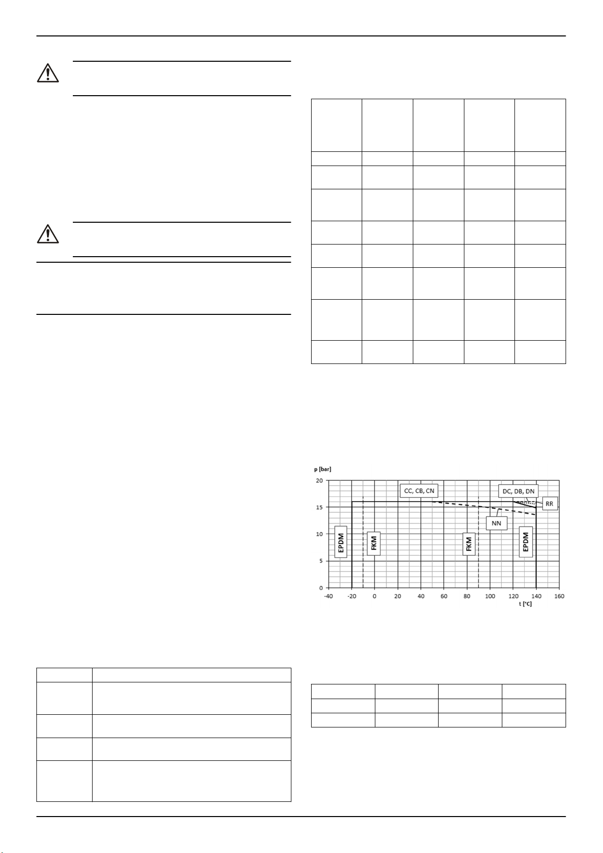
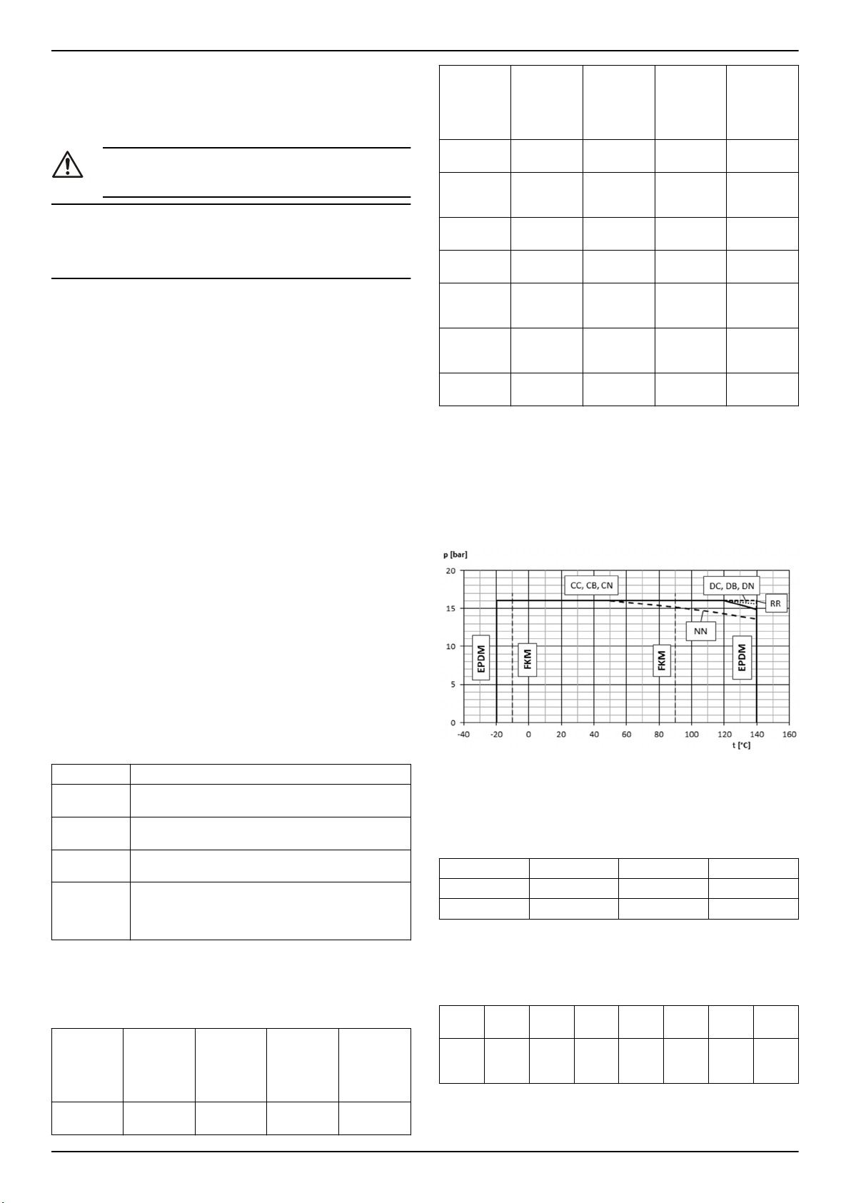
3.7 Limiti d'impiego
Pressione massima di lavoro
Il diagramma mostra la massima pressione di lavoro in base al modello di pompa e alla temperatura del liquido pompato.
Marchio IMQ , TUV o IRAM o altri marchi (solo per l'elettropompa)
Salvo diversa specifica indicazione, per i prodotti recanti un marchio di
approvazione per la sicurezza elettrica, l’approvazione è riferita esclusivamente all’elettropompa.
3.4 Struttura del design
• Dimensioni in conformità a EN 733 e dimensioni di estensione ulteriori non standardizzate
• Pompa con corpo a chiocciola con connessione di albero o flangia di supporto posteriore estraibile
• Singolo stadio
• Per montaggio orizzontale
Parte
Corpo pompa • Corpo pompa a spirale diviso radiale con scarico
Girante • Girante radiale chiusa con anelli usura su en-
Tenuta dell'albero
Cuscinetti • Cuscinetti a sfera radiali
Descrizione
radiale
• Anello usura sostituibile
trambi i lati
• Tenuta meccanica singola sec. EN 12756
• Tenuta meccanica a cartuccia opzionale
• Lubrificazione con grasso
• Opzionale: lubrificazione con grasso (flangia di
supporto avanzata)
e-NSC Installation, Operation, and Maintenance Manual 5
P
+ P
1max
P
1max
P
max
PN Pressione massima d'esercizio
Intervalli di temperatura del liquido
Versione
Standard EPDM -20 °C (-4 °F) 140 °C (284 °F)
Opzionale FPM (FKM) -10 °C (14 °F) 90 °C (194 °F)
Per requisiti speciali, contattare il Servizio di Vendita ed Assistenza.
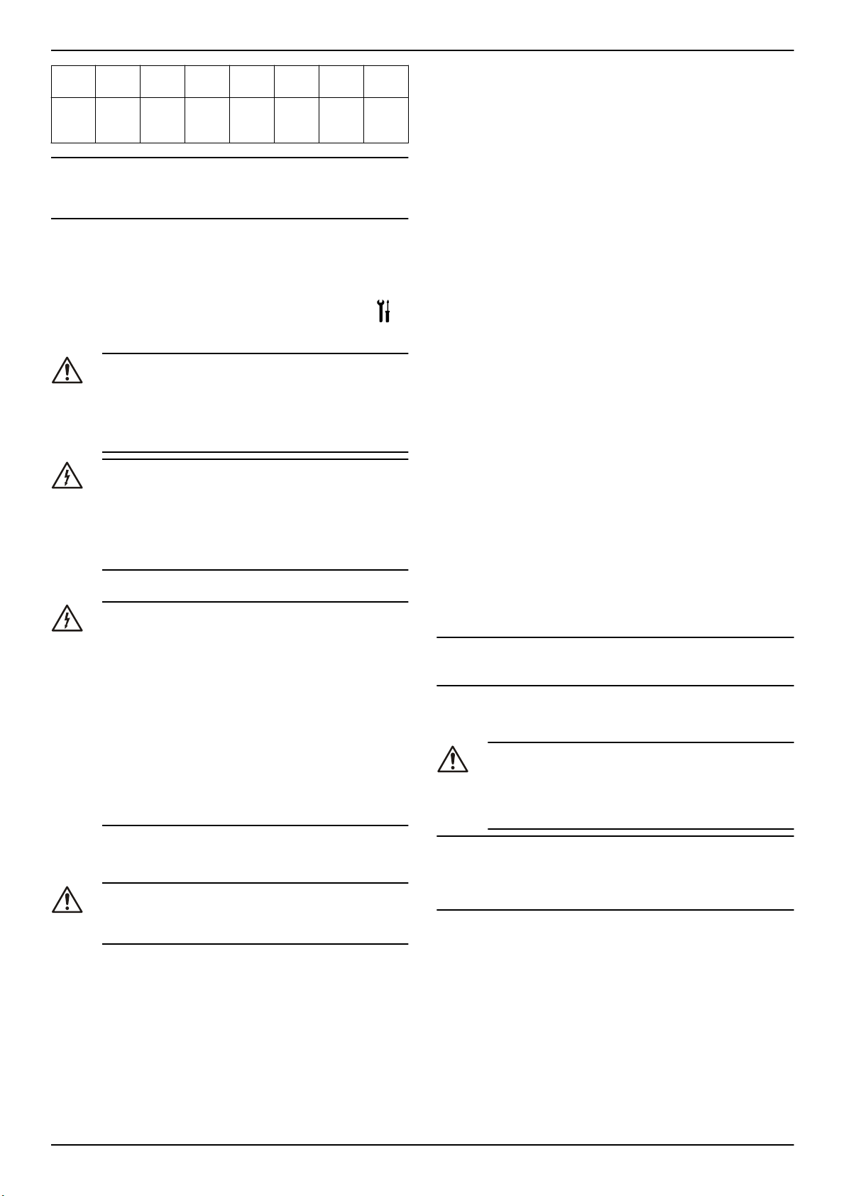
Numero massimo di avviamenti orari
La seguente tabella mostra il numero di avviamenti consentiti in un'ora
per motori forniti da Lowara:
≤ PN
max
Pressione massima di ingresso
Pressione massima generata dalla pompa
Guarnizione Minima Massima
Page 6
it - Istruzioni originali
kW 0,25 -
Avviamenti
orari
NOTA BENE:
In caso di utilizzo di un motore diverso da quello di serie fornito con l'elettropompa, controllare le relative istruzioni per verificare il numero
consentito di avvii per ora.
Livello di rumore
Consultare i livelli di pressione sonora superficiale di misura LpA nella
Tabella 15 .
4,00 -
3,00
60 40 25 16 8 4 3
11 - 22 30 - 37 45 - 75 90 –
7,50
160
185 -
355
4 Installazione
Precauzioni
AVVERTENZA:
• Osservare le vigenti norme antinfortunistiche.
• Utilizzare adeguate attrezzature e protezioni.
• Fare sempre riferimento alle norme, alla legislazione e
ai codici locali e/o nazionali vigenti relativi alla selezione del luogo di installazione e all'allacciamento di linee
idrauliche ed elettriche.
PERICOLO ELETTRICO:
• Verificare che tutti i collegamenti siano eseguiti da installatori qualificati e in conformità alle norme vigenti.
• Prima di iniziare a lavorare sull'unità, controllare che
l’alimentazione elettrica sia disinserita e che l'unità e il
quadro di comando non possano riavviarsi, neppure accidentalmente. Questo vale anche per il circuito di controllo.
Messa a terra (massa)
PERICOLO ELETTRICO:
• Collegare sempre il conduttore esterno di protezione al
morsetto di terra prima di effettuare altri collegamenti
elettrici.
• È necessario collegare a terra tutte le apparecchiature.
Questo vale per le apparecchiature della pompa, il trascinatore e qualsiasi apparecchiatura di monitoraggio.
Testare il conduttore di messa a terra per verificare se è
connesso correttamente.
• Se per errore si stacca il cavo del motore, il conduttore
di messa a terra deve essere l'ultimo a staccarsi dal terminale. Verificare che il conduttore di messa a terra sia
più lungo dei conduttori di fase. Vale per entrambe le
estremità del cavo.
• Quale protezione supplementare dalle scosse elettriche
letali. Installare un interruttore differenziale ad alta sensibilità (30 mA).
• Contattare il Servizio di Vendita ed Assistenza se:
• Le condizioni di umidità relativa dell'aria superano quelle
previste dalle linee guida.
• La temperatura ambiente supera i +40 °C (+104 °F).
• L'unità è posizionata a più di 1000m (3000 piedi) sul livello
del mare. Può essere necessario ridurre il valore nominale
della potenza erogabile dal motore o sostituirlo con uno più
potente.
Per informazioni sul livello di riduzione della potenza, vedere Tabella
16 .
Posizioni della pompa e spazio attorno alla pompa
Garantire che attorno alla pompa ci siano adeguati spazio libero e illuminazione. Assicurarsi che sia di facile accesso per le operazioni di installazione e manutenzione
Installazione al di sopra del liquido da aspirare (soprabattente)
La massima altezza di aspirazione teorica per qualsiasi pompa è di
10,33 m. In pratica, quanto segue influisce sulla capacità di aspirazione della pompa:
• Temperatura del liquido pompato
• Altezza sul livello del mare (in un impianto aperto)
• Pressione di sistema (in un impianto chiuso)
• Resistenza delle tubazioni
• Perdita di carico intrinseca della pompa
• Differenze di altezza
Per calcolare l'altezza massima dal livello del liquido su cui installare la
pompa utilizzare la seguente equazione.
(pb*10,2 - Z) ≥ NPSH + Hf + Hv + 0,5
p
Pressione barometrica in bar (in un impianto chiuso è la pres-
b
sione del sistema)
NPSH Valore in metri della perdita di carico intrinseca della pompa
H
Perdita di carico totale in metri causata dal passaggio del liqui-
f
do la tubazione di aspirazione della pompa
H
Pressione di vapore in metri corrispondente alla temperatura T
v
°C del liquido
0,5 Margine di sicurezza consigliato (m)
Z Altezza massima alla quale è installabile la pompa (m)
Per ulteriori informazioni, vedere Figura 17 .
(pb*10,2 - Z) deve essere sempre un numero positivo.
NOTA BENE:
Non superare la capacità di aspirazione della pompa in quanto questo
potrebbe causare cavitazione e danneggiare la pompa.
4.1.2 Requisiti delle tubazioni
Precauzioni
AVVERTENZA:
• Utilizzare tubi adatti alla massima pressione di lavoro
della pompa. In caso contrario, l'impianto può subire
cedimenti, con il rischio di lesioni personali
• Verificare che tutti i collegamenti siano eseguiti da installatori qualificati e in conformità alle norme vigenti.
4.1 Requisiti dell'impianto
4.1.1 Collocazione della pompa
PERICOLO:
Non utilizzare questa unità in ambienti che possono contenere polveri o gas infiammabili/esplosivi o chimicamente aggressivi.
Linee guida
Rispettare le seguenti linee guida relative alla collocazione del prodotto:
• Assicurarsi che non vi siano ostacoli al regolare flusso dell'aria di
raffreddamento emesso dalla ventola del motore.
• Assicurarsi che eventuali perdite di liquido o altri eventi simili non
possano allagare il luogo di installazione o sommergere l'unità
• Se possibile, posizionare la pompa poco al di sopra del livello del
pavimento.
• La temperatura ambiente deve essere compresa tra 0 °C (+32 °F)
e +40 °C (+104 °F)
• L'umidità relativa dell'aria ambiente deve essere inferiore al 50%
a +40 °C (+104 °F).
NOTA BENE:
Se la pompa viene collegata a un sistema idrico pubblico, osservare
tutte le normative emesse dalle autorità preposte e dalle aziende responsabili della gestione idrica al pubblico. Se richiesto, installare un
appropriato dispositivo antiriflusso sul lato di aspirazione..
Lista di controllo delle tubazioni
Controllare che siano soddisfatti i seguenti requisiti:
• Tutte le tubazioni sono supportate in modo indipendente, le tubazioni non devono pesare sull'unità.
• Che vengano utilizzati tubi o raccordi flessibili, per evitare che le
vibrazioni della pompa di trasferiscano alle tubazioni e viceversa.
• Utilizzare curve ampie, evitare di utilizzare gomiti che causino eccessiva perdita di carico.
• La tubazione di aspirazione è perfettamente a tenuta ed ermetica.
• Se la pompa è utilizzata in un circuito aperto, il diametro del tubo
di aspirazione è adatto alle condizioni di installazione. Il tubo di
aspirazione non deve essere più piccolo del diametro della bocca
di aspirazione.
• Se la tubazione di aspirazione deve essere avere un diametro
maggiore della bocca di della pompa, che sia installata una riduzione eccentrica.
6 e-NSC Installation, Operation, and Maintenance Manual
Page 7
it - Istruzioni originali
• Se la pompa è posta al di sopra del liquido da aspirare (soprabattente), all'estremità della tubazione di aspirazione è installata una
valvola di fondo.
• La valvola di fondo è completamente immersa nel liquido, in modo tale che l'aria non possa entrare attraverso il vortice di aspirazione, quando il liquido è al livello minimo.
• Valvole di intercettazione di dimensione adatta sono installate nella tubazione di aspirazione e nella tubazione di mandata (a valle
della valvola di ritegno) per la regolazione della portata della pompa, per l'ispezione e la manutenzione della pompa.
• Una valvola di intercettazione di dimensione adatta è installata
nella tubazione di mandata (a valle della valvola di ritegno) per la
regolazione della portata della pompa e per l'ispezione e la manutenzione della pompa.
• Una valvola di ritegno è installata sulla tubazione di mandata per
prevenire il riflusso attraverso la pompa quando la pompa viene
spenta.
AVVERTENZA:
Non utilizzare la valvola di intercettazione sul lato di mandata in posizione chiusa, per ridurre la portata della pompa, per
più di pochi secondi. Se la pompa deve funzionare con il lato
di mandata chiuso per più di qualche secondo, installare un
circuito di by-pass per impedire il surriscaldamento del liquido all'interno della pompa.
Per illustrazioni che mostrano i requisiti delle tubazioni, vedere Figura
18 e Figura 19 .
4.2 Requisiti elettrici
• I requisiti specificati possono essere superati dalle normative locali vigenti.
• In caso di impianti antincendio (idranti e/o sprinkler) verificare la
normativa locale vigente.
Lista di verifica per la connessione elettrica
Controllare che siano soddisfatti i seguenti requisiti:
• I conduttori elettrici sono protetti da temperature troppo elevate,
vibrazioni e urti.
• La linea di alimentazione è dotata di:
• Un dispositivo di protezione da corto circuito
• Un dispositivo di sezionamento dalla rete con distanza di
apertura dei contatti di almeno 3 mm.
Lista di verifica per il quadro elettrico di comando
NOTA BENE:
Il quadro elettrico deve essere idoneo rispetto ai valori nominali dell'elettropompa. Abbinamenti inappropriati possono non garantire la protezione del motore.
Controllare che siano soddisfatti i seguenti requisiti:
• Il quadro elettrico deve proteggere il motore da eventuali sovraccarichi e cortocircuiti.
• Installare la protezione da sovraccarico adeguata (relè termico o
salvamotore)
Tipo di pompa
Elettropompa monofase di serie
≤ 1,5 kW:
Elettropompa trifase e altra mo-
2
nofase:
• Il quadro elettrico deve essere dotato di un sistema di protezione
contro la marcia a secco a cui collegare un pressostato, un galleggiante, le sonde o altri dispositivi altri dispositivi idonei al sistema di protezione.
• Per l'utilizzo sul lato di aspirazione della pompa si consigliano i
seguenti dispositivi:
• Se il liquido viene pompato da un acquedotto, utilizzare un
pressostato.
• Se il liquido viene pompato da una vasca o un serbatoio di
stoccaggio, utilizzare un galleggiante o delle sonde.
Protezione
• protezione termo-amperometrica a riarmo automatico incorporata (motoprotettore)
• Protezione da cortocircuito
(a cura dell'installatore)
• Protezione termica (a cura
dell'installatore)
• Protezione da cortocircuito
(a cura dell'installatore)
1
• In caso di utilizzo di relè termici, si consiglia di scegliere relè in
grado di segnalare gli errori della fase.
Lista di controllo verifica per il motore
AVVERTENZA:
• Leggere il manuale d'uso per verificare la presenza di
un dispositivo di protezione se si utilizza un motore diverso da quello di serie.
• Se il motore è dotato di protettori termici automatici, fare attenzione al rischio di avviamenti imprevisti in relazione al sovraccarico. Non utilizzare tali motori per
estinguere incendi e per sistemi antincendio ad acqua
polverizzata.
NOTA BENE:
• Utilizzare solo motori bilanciati dinamicamente con mezza linguetta posta all'estremità dell'albero (IEC 60034-14) e con grado di vibrazione normale (N).
• La tensione e la frequenza di rete devono corrispondere alle specifiche riportare sulla targa dati.
• Utilizzare solo motori monofase o trifase le cui dimensioni e la cui
potenza siano conformi agli standard europei.
Generalmente i motori possono funzionare con una tensione di alimentazione avente una tolleranza di:
Frequenza Hz Fase ~ UN [V] ± %
50 1 220 – 240 ± 6
3 230/400 ± 10
400/690 ± 10
60 1 220 – 230 ± 6
3 220/380 ± 5
380/660 ± 10
Usare cavi a norma con 3 conduttori (2 + Terra) per versioni monofase
e con 4 conduttori (3 + Terra) per versioni trifase.
4.3 Installazione della pompa
4.3.1 Installazione meccanica
Prima dell'installazione, controllare quanto segue:
• Utilizzare un calcestruzzo di classe di resistenza alla compressione C12/15 che soddisfa i requisiti della classe di esposizione XC1
come da EN 206-1.
• La superficie di montaggio deve essere preparata e deve essere
completamente orizzontale e piana.
• Rispettare i pesi indicati.
Montare l'unità a una fondazione
Per informazioni sulla base della pompa e i fori di ancoraggio, vedere
Figura 20 .
Verificare che la fondazione sia stata preparata in conformità alle dimensioni indicate nel disegno di massima/disegno generale.
1. Posizionare la pompa sulla fondazione e livellarla con l'aiuto di
una livella a bolla posta sull'albero e sull'ugello di scarico.
La deviazione consentita è 0,2 mm/m.
2. Rimuovere i tappi che coprono le bocche.
3. Allineare la pompa e le flange delle tubazioni su entrambi i lati
della pompa. Verificare l'allineamento dei bulloni.
4. Fissare le tubazioni alla pompa tramite i bulloni. Non forzare il posizionamento delle tubazioni.
5. Utilizzare degli spessori (2) per la compensazione in altezza, se
necessario.
Collocare sempre gli spessori, se presenti, immediatamente a sinistra e a destra dei bulloni di fondazione (3) tra la piastra di base/telaio di fondazione e la fondazione. Per una distanza da bullone a bullone (L) >800 mm, collocare spessori aggiuntivi (2) in posizione centrale tra i fori dei bulloni.
6. Assicurarsi che tutti gli spessori siano perfettamente a filo.
7. Inserire i bulloni di fondazione (3) nei fori forniti.
1
fusibili aM (avviamento motore), oppure interruttore magnetotermico con curva C e Icn ≥ 4,5 kA o altro dispositivo equivalente.
2
relè termico di sovraccarico con classe di intervento 10A + fusibili aM (avviamento motore), oppure interruttore magnetotermico di protezione motore con classe
di intervento 10A.
e-NSC Installation, Operation, and Maintenance Manual 7
Page 8
it - Istruzioni originali
8. Utilizzare del calcestruzzo per collocare i bulloni di fondazione (3)
nella fondazione.
9. Attendere che il calcestruzzo faccia presa, quindi livellare la piastra di base.
10. Serrare i bulloni di fondazione (3) in modo saldo e uniforme.
Nota:
• Per le piastre base, si consiglia di stuccare la piastra di base con
calcestruzzo a basso ritiro.
• Se la trasmissione di vibrazioni può causare problemi, inserire antivibranti tra la pompa e le fondazione.
Montare la pompa al telaio di base
Assicurarsi che le indicazioni seguenti siano rispettate:
• Telaio di base solido che non si piega né vibra durante il funzionamento (risonanza).
• Superfici di montaggio dei piedini della pompa e motore sul telaio
di base devono essere piani (si consiglia di eseguire le lavorazioni necessarie).
• Deve essere garantito un fissaggio sicuro della pompa e del motore.
• Deve essere lasciato uno spazio adeguato tra la pompa e l'albero
motore a seconda del giunto utilizzato.
• Tra pompa e telaio di base deve esserci un dislivello tale che, in
caso di sostituzione, possa essere regolata la stessa altezza tra
la linea inferiore e centrale (raccomandata regolazione verticale
4-6 mm).
4.3.2 Lista di controllo delle tubazioni
Controllare che sia rispettato quanto segue:
• La linea di aspirazione soprabattente è stata collocata con una
pendenza crescente, alla linea di altezza di aspirazione positiva
con una pendenza decrescente verso la pompa.
• I diametri nominali delle tubazioni sono almeno pari ai diametri
nominali degli ugelli della pompa.
• Le tubazioni sono state ancorate in prossimità della pompa e collegate senza trasmettere sollecitazioni o deformazioni.
ATTENZIONE:
Cordoni di saldatura, depositi e altre impurità nelle tubazioni
danneggiano la pompa.
• Liberare le tubazioni da eventuali impurità.
• Se necessario, installare un filtro.
• Seguire “Forze e coppie di serraggio consentite sulle flange", vedere Figura 21 .
I dati sulle forze e sui momenti si applicano solo alle tubazioni statiche.
I valori sono applicabili solo se la pompa viene installata su una piastra
di base e fissata a una fondazione rigida e piana.
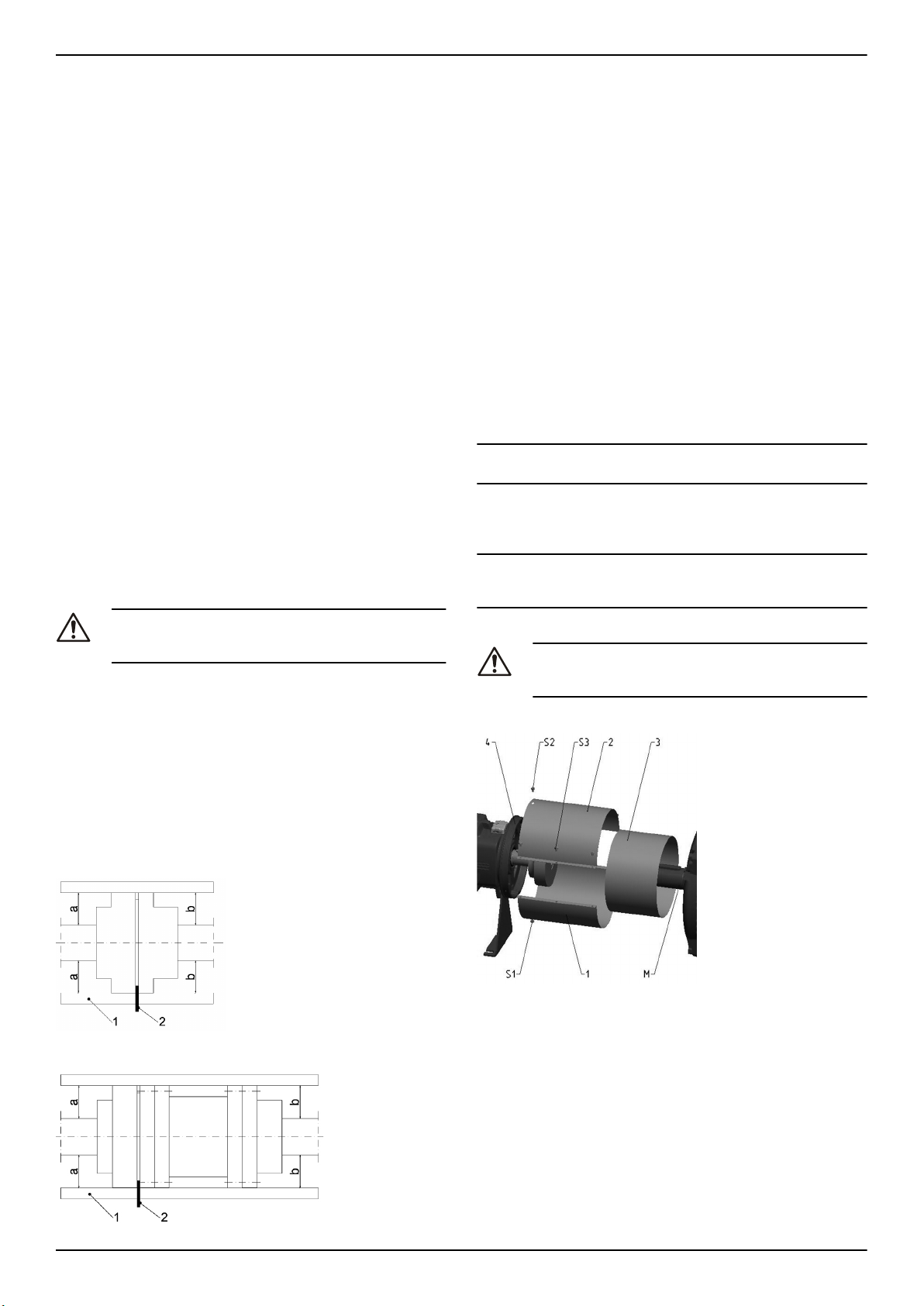
4.3.3 Allineamento giunto
Dopo il montaggio alla fondazione e il collegamento delle tubazioni, il
giunto deve essere nuovamente regolato, anche se l'unità è stata consegnata completamente montata sul telaio.
Figura 1: Allineamento di giunto standard
1. Metà superiore della protezione giunto
2. Metà inferiore della protezione giunto
3. Elemento di regolazione
Rimuovere la protezione giunto.
1. Allentare il piede di supporto e riserrarlo senza trasmettere sollecitazioni e deformazioni.
2. Posizionare la riga (1) assialmente su entrambe le metà del giunto.
3. Lasciare la riga (1) in questa posizione e ruotare il giunto a mano.
• Il giunto è allineato correttamente se le distanze a e b ai rispettivi alberi sono uguali in tutti i punti intorno alla circonferenza.
• La deviazione radiale e assiale tra le due metà del giunto
non deve superare i valori nella tabella xyz, durante l'arresto
nonché a temperatura operativa e sotto pressione di ingresso.
4. Verificare la distanza (per le dimensioni, v. lo schema generale di
disposizione) tra le due metà del giunto attorno alla circonferenza
con un indicatore (4). Il giunto è correttamente allineato se la distanza tra le due metà del giunto è la stessa in tutti i punti attorno
alla circonferenza.
• La deviazione radiale e assiale tra le due metà del giunto
non deve superare i valori nella tabella xyz, durante l'arresto
nonché a temperatura operativa e sotto pressione di ingresso.
NOTA BENE:
Montare la protezione giunto dopo l'allineamento e prima dell'avvio.
Nota: controllare nuovamente l'allineamento del giunto in condizioni di
funzionamento e pressione del sistema (se disponibile) e correggere,
se necessario. Prestare prima attenzione al capitolo 6! Deve essere
possibile ruotare l'unità a mano facilmente e uniformemente.
NOTA BENE:
Un allineamento non corretto dell'unità può provocare danni a giunto e
unità.
4.3.4 Installazione della protezione del giunto
ATTENZIONE:
Non mettere mai in funzione la pompa senza la protezione
giunto correttamente installata.
Figura 3: Parti della protezione giunto
1. Metà inferiore della protezione giunto
2. Metà superiore della protezione giunto
3. Metà di regolazione
Figura 2: Allineamento di giunto distanziale
1. Avvitare la metà inferiore della protezione giunto (1) con delle viti
(S1) al fondo dell'anello della copertura del cuscinetto (4).
2. Inserire l'elemento di regolazione (3) con la scanalatura verso il
basso e premere in direzione assiale sul motore.
3. Avvitare la metà superiore della protezione giunto (1) con delle viti (S2) al lato superiore dell'anello della copertura del cuscinetto
(4).
4. Avvitare insieme le parti 1 e 2; questa operazione fissa l'elemento
di regolazione.
8 e-NSC Installation, Operation, and Maintenance Manual
Page 9
it - Istruzioni originali
4.3.5 Installazione elettrica
1. Rimuovere le viti del coperchio della morsettiera.
2. Collegare e assicurare i cavi di alimentazione secondo il relativo
schema d'installazione.
Per gli schemi d'installazione, vedere Figura 24 . Gli schemi sono
disponibili anche sul retro del coperchio della scatola del terminale.
a) Collegare il conduttore di terra (massa).
Assicurarsi che il conduttore di terra (massa) sia più lungo
dei conduttori di fase.
b) Collegare i conduttori di fase.
3. Montare il coperchio della scatola morsettiera.
NOTA BENE:
Serrare correttamente i pressacavi per garantire l'adeguata protezione contro lo scorrimento del cavo e l'umidità.
4. Se il motore non è provvisto di protezione termica a riarmo automatico, regolare la protezione da sovraccarico secondo l'elenco
seguente.
• Se il motore viene utilizzato a pieno carico, regolare al valore nominale della corrente dell'elettropompa (targa dati).
• Se il motore viene utilizzato a carico parziale,regolare al valore alla corrente d'esercizio (pinza amperometrica).
• Se è presente un sistema di avviamento stella-triangolo, regolare il relè termico sul 58% della corrente nominale o della
corrente di esercizio (solo per motori trifase).
5 Messa in funzione, avvio, funzionamento e spegnimento
Precauzioni
AVVERTENZA:
• Fare attenzione al liquido scaricato in modo che non
possa arrecare danni a cose o persone.
• I protettori del motore possono causare un riavvio imprevisto del motore. Questo può determinare gravi lesioni personali.
• Non mettere mai in funzione la pompa senza la protezione giunto correttamente installata.
ATTENZIONE:
• Durante il funzionamento, le superfici esterne della
pompa e del motore non devono superare i 40ºC
(104ºF). Non toccare il corpo in alcun punto senza indossare l'equipaggiamento di protezione.
• Non porre materiale combustibile vicino alla pompa.
NOTA BENE:
• NON mettere in funzione la pompa al di sotto della portata nominale minima, a secco o senza adescamento.
• Non far funzionare mai la pompa con la valvola di intercettazione
(aspirazione o mandata) chiusa per più di pochi secondi.
• Non far funzionare mai la pompa con la valvola di intercettazione
di aspirazione chiusa.
• Non esporre la pompa inattiva a temperature di congelamento.
Scaricare tutto il liquido che si trova all'interno della pompa. La
mancata osservanza della prescrizione può determinare il congelamento del liquido e danneggiare la pompa.
• La somma della pressione sul lato di aspirazione (rete principale,
serbatoio a gravità) e la pressione massima erogata dalla pompa
non deve superare la massima pressione di lavoro permessa
(pressione nominale PN) della pompa.
• Non utilizzare la pompa in caso di cavitazione. La cavitazione può
danneggiare i componenti interni.
Livello di rumore
Per informazioni sui livelli di rumore della sola pompa e della pompa
con motore in dotazione di serie, v. Tabella 10.
5.1 Riempire la pompa
Per informazioni sui collegamenti aggiuntivi della pompa, vedere Figu-
ra 25 .
Installazioni con il livello del liquido al di sopra della pompa
(aspirazione sottobattente)
Per una figura che mostra le parti della pompa, vedere Figura 26 .
1. Chiudere la valvola di intercettazione a valle della pompa.
2. Rimuovere il tappo di riempimento (3) o dell'indicatore (1) e aprire
la valvola di intercettazione a monte, finché l'acqua non fuoriesce
dal foro.
a) Chiudere il tappo di riempimento (3) o dell'indicatore (1).
Installazioni con il livello del liquido al di sotto della pompa
(soprabattente)
Per una figura che mostra le parti della pompa, vedere Figura 27 .
1. Tutto il sistema di tubazioni vuoto:
a) Aprire la valvola di intercettazione a monte della pompa e
chiudere la
b) Rimuovere il tappo di riempimento (3) e il tappo dell'indicato-
re (1); utilizzare un imbuto per riempire la pompa attraverso
il tappo di riempimento (3) finché l'acqua non fuoriesce dal
foro.
c) Serrare il tappo di riempimento (3) e il tappo dell'indicatore
(1).
2. Sistema di tubazioni di scarico riempito:
a) Aprire la valvola di intercettazione a monte della pompa e
chiudere la valvola di intercettazione a valle.
b) Rimuovere il tappo dell'indicatore (1) finché l'acqua non fuo-
riesce dal foro.
c) Serrare il tappo dell'indicatore (1).
5.2 Controllo del senso di rotazione (motore trifase)
Attenersi a questa procedura prima dell'avvio.
1. Individuare le frecce sulla lanterna, sul giunto e/o sul copriventola
del motore per determinare il senso di rotazione corretto.
2. Avviare il motore.
3. Controllare rapidamente il senso di rotazione attraverso la protezione del giunto o il copriventola del motore.
4. Fermare il motore.
5. Se il senso di rotazione è errato, attenersi alla seguente procedura:
a) Scollegare l'alimentazione.
b) Nella morsettiera del motore o nel quadro elettrico di coman-
do, scambiare la posizione di due dei tre fili del cavo di alimentazione.
Per gli schemi di cablaggio, vedere Figura 24 .
c) Verificare nuovamente il senso di rotazione.
5.3 Avviamento della pompa
La responsabilità di controllare la portata corretta e la temperatura del
liquido pompato spetta all'installatore o al proprietario.
Prima dell'avviamento della pompa, accertarsi che:
• La pompa sia correttamente collegata all'alimentazione elettrica.
• La pompa è montata correttamente secondo le istruzioni fornite in
Riempire la pompa (capitolo 5).
• La valvola di intercettazione a valle della pompa sia chiusa.
1. Avviare il motore.
2. Aprire gradualmente la valvola di intercettazione sul lato di mandata della pompa.
Alle condizioni di esercizio previste, la pompa deve funzionare in
modo silenzioso e regolare. Altrimenti, fare riferimento a Risolu-
zione dei problemi.
6 Manutenzione
Precauzioni
PERICOLO ELETTRICO:
Scollegare e isolare l'alimentazione elettrica prima d'installare l'unità o sottoporla a manutenzione.
e-NSC Installation, Operation, and Maintenance Manual 9
Page 10
it - Istruzioni originali
AVVERTENZA:
• La manutenzione deve essere eseguita solo da personale esperto e qualificato.
• Osservare le vigenti norme antinfortunistiche.
• Utilizzare adeguate attrezzature e protezioni.
• Fare attenzione al liquido scaricato in modo che non
possa arrecare danni a cose o persone.
6.1 Assistenza
In caso l’utilizzatore desideri approntare un piano di manutenzione programmata, tenere presente che le scadenze dipendono dal tipo di liquido pompato e dalle condizioni di esercizio.
Contattare il rappresentante di vendita e assistenza di zona per eventuali richieste o informazioni riguardo l'assistenza o la manutenzione
ordinaria.
Può essere necessaria la manutenzione straordinaria per la pulizia
delle parti idrauliche e/o sostituzione di altre parti usurate.
Tipi di cuscinetto
• Lubrificazione e sostituzione dei lubrificanti dei cuscinetti degli
elementi volventi
• Cuscinetti lubrificati con grasso
• I cuscinetti lubrificati con grasso sono stati imballati con
grasso in fabbrica. Vedere la dimensione del cuscinetto e il
tipo di lubrificazione nella tabella 6.
Pompe con cuscinetti lubrificati a vita
Le pompe con cuscinetti lubrificati a vita non richiedono alcuna manutenzione ordinaria pianificata.
Pompe con cuscinetti ri-lubrificabili
• Lubrificare a 4000 ore di esercizio, ma almeno una volta all'anno.
Pulire prima gli ingrassatori (SN).
• Utilizzare grasso NLGI Grado 2 o equivalente.
• Per le quantità approssimative di grasso, vedere tabella 6.
6.2 Valori della coppia di serraggio
Per informazioni sui valori della coppia di serraggio e dei dati della
pompa, vedere Figura 28 , dati della piastra di base Tabella 29 .
6.3 Lista di controllo ispezione
Controllare il giunto
Controllare la tenuta meccanica Controllare la presenza di perdite
Controllo delle tenute dei cuscinetti
Controllare gli elementi flessibili
del giunto. Sostituire le parti appropriate in caso di segni di usura
e controllare l'allineamento.
della tenuta meccanica. Sostituire
la tenuta meccanica se vengono
rilevate perdite.
Controllare la sede corretta degli
anelli di tenuta ssiali montati sull'albero. Il labbro di tenuta deve
essere toccato solo delicatamente.
6.4 Smontare e sostituire le parti della pompa
Per maggiori informazioni sulle parti di ricambio e sul montaggio e lo
smontaggio della pompa, vedere Figura 1 , Figura 2 , Figura 3 o Figura
4 .
V. le Istruzioni di riparazione e montaggio, che possono essere scaricate dalla nostra home page.
7 Risoluzione dei problemi
7.1 Risoluzioni dei guasti per gli utenti
L'interruttore generale è inserito. L'elettropompa non si avvia.
L'elettropompa si avvia, ma dopo un tempo variabile interviene la protezione termica.
Causa Soluzione
Dei corpi estranei (sostanze
solide o fibrose) all’interno della pompa hanno bloccato le
giranti.
La pompa è sovraccaricata
poiché aspira un liquido denso
e viscoso.
La pompa funziona, ma la portata è scarsa o nulla.
Causa Soluzione
La pompa è ostruita. Contattare il Servizio di Vendita ed Assistenza.
Le istruzioni per la risoluzione dei problemi riportate nelle tabelle seguenti sono riservate agli addetti all'installazione.
Contattare il Servizio di Vendita ed
Assistenza.
Verificare i requisiti effettivi di potenza
in base alle caratteristiche del liquido
pompato e poi contattare il Servizio di
Vendita ed Assistenza.
7.2 L'interruttore generale è inserito. L'elettropompa non si avvia.
Causa Soluzione
Mancanza di alimentazione
elettrica.
È intervenuta la protezione
termica incorporata nella
pompa (se presente).
È intervenuto il relè termico o
il salvamotore posto nel quadro elettrico di comando.
E' intervenuto il dispositivo di
protezione contro la marcia a
secco.
Si sono bruciati i fusibili di
protezione della pompa o dei
circuiti ausiliari.
• Ripristinare l'alimentazione.
• Assicurarsi che tutti i collegamenti elettrici all'alimentazione di rete
siano intatti.
Attendere che la pompa si raffreddi.
La protezione termica si riarma automaticamente.
Riarmare la protezione termica.
Verificare:
• Il livello del liquido nella vasca o
la pressione della rete
• Il dispositivo di protezione e i suoi
cavi di collegamento
Sostituire i fusibili.
7.3 L'elettropompa si avvia, ma immediatamente dopo interviene la protezione termica o scattano i fusibili
Causa
Il cavo di alimentazione è danneggiato.
La protezione termica o i fusibili non sono adatti alla corrente del motore.
Il motore elettrico è in cortocircuito.
Il motore si sovraccarica. Verificare le condizioni di esercizio
Soluzione
Verificare il cavo e sostituirlo, se necessario.
Verificare i componenti e sostituirli, se
necessario.
Verificare i componenti e sostituirli, se
necessario.
della pompa e riarmare la protezione.
7.4 L'elettropompa si avvia, ma dopo poco tempo interviene la protezione termica o scattano i fusibili
Causa
È intervenuta la protezione termica incorporata nella pompa
(se presente).
E' intervenuto il dispositivo di
protezione contro la marcia a
secco.
Soluzione
Attendere che la pompa si raffreddi. La protezione termica si riarma
automaticamente.
Controllare il livello del liquido nella
vasca o la pressione dalla rete.
Causa
Il quadro elettrico di comando è collocato in un'area eccessivamente riscaldata o è esposto direttamente
ai raggi solari.
Soluzione
Proteggere il quadro elettrico di
comando dalle fonti di calore e
dal sole.
10 e-NSC Installation, Operation, and Maintenance Manual
Page 11
it - Istruzioni originali
Causa Soluzione
La tensione di alimentazione non è
entro i limiti di funzionamento del
motore.
Mancanza di una fase dell'alimentazione elettrica.
Verificare le condizioni di esercizio della pompa.
Verificare
• alimentazione
• collegamento elettrico
7.5 L'elettropompa si avvia, ma dopo un tempo variabile interviene la protezione termica
Causa Soluzione
Dei corpi estranei (sostanze
solide o fibrose) all’interno
della pompa hanno bloccato
le giranti.
La pompa eroga una portata
superiore al limite indicato
sulla targa dati.
La pompa è sovraccaricata
poiché aspira un liquido denso e viscoso.
I cuscinetti del motore sono
usurati.
Rivolgersi al rappresentante di vendita
e assistenza di zona.
Chiudere parzialmente la valvola di intercettazione posta a valle fino a che
la portata erogata non rientra nei limiti
previsti sulla targa dati.
Verificare i requisiti effettivi di potenza
in base alle caratteristiche del liquido
pompato.
Rivolgersi al rappresentante di vendita
e assistenza di zona.
7.6 L'elettropompa si avvia, ma è attiva la protezione generale dell'impianto
Causa
Un cortocircuito nell'impianto elettrico. Controllare l'impianto elettrico.
Soluzione
7.7 L'elettropompa si avvia, ma è attivo il dispositivo di protezione da corrente residua (RCD) dell'impianto
Causa
Ci sono dispersioni a
terra.
Soluzione
Verificare l'isolamento dei componenti dell'impianto elettrico.
7.8 La pompa funziona, ma la portata è scarsa o nulla
Causa
Presenza di aria nella
pompa o nelle tubazioni.
La pompa non è adescata correttamente.
Lo strozzamento in mandata è eccessivo.
Le valvole sono bloccate
in posizione chiusa o parzialmente chiusa.
La pompa è ostruita. Rivolgersi al rappresentante di vendita e
I tubi sono ostruiti. Controllare e pulire i tubi.
Il senso di rotazione della
girante è errato
(versione trifase)
.
Soluzione
• Spurgare l'aria
Arrestare la pompa e ripetere la procedura
di adescamento.
Se il problema persiste:
• Verificare che la tenuta meccanica
non perda.
• Verificare la perfetta tenuta della tubazione di aspirazione
• Sostituire eventuali valvole che perdono.
Aprire la valvola.
Smontare e pulire le valvole.
assistenza di zona.
Cambiare la posizione di due delle fasi
sulla morsettiera del motore o nel quadro
elettrico di comando.
Causa Soluzione
L'aspirazione soprabattente è eccessiva o la
perdita di carico nei tubi
di aspirazione è eccessiva.
Verificare le condizioni di esercizio della
pompa. Se necessario, procedere come
segue:
• Diminuire il dislivello
• Aumentare il diametro del tubo di
aspirazione
7.9 L'elettropompa si ferma e poi ruota nel senso sbagliato
Causa Soluzione
Presenza di una perdita in uno o entrambi i seguenti componenti:
• Il tubo di aspirazione
• La valvola di fondo o la check valvola di ritegno
È presente dell'aria nel tubo di aspirazione. Spurgare l'aria
Riparare o sostituire
i componenti guasti.
7.10 La pompa si avvia troppo frequentemente.
Causa Soluzione
Presenza di una perdita in uno o entrambi i
seguenti componenti:
• Il tubo di aspirazione
• La valvola di fondo o la check valvola
di ritegno
Autoclave con la membrana rotta o privo di
precarica d'aria.
Riparare o sostituire i
componenti guasti.
Vedere le apposite istruzioni nel manuale dell’autoclave.
7.11 La pompa vibra e genera troppo rumore
Causa
Pompa in cavitazione
I cuscinetti del motore sono usurati.
Presenza di corpi
estranei all’interno
della pompa.
Per ogni situazione non contemplata, fare riferimento al rappresentante di vendita e assistenza di zona.
Soluzione
Ridurre la portata richiesta chiudendo parzialmente la valvola di intercettazione a valle della
pompa. Se il problema persiste verificare le condizioni di esercizio della pompa (dislivelli, perdite
di carico, temperatura del liquido, ecc...)
Rivolgersi al rappresentante di vendita e assistenza di zona.
Rivolgersi al rappresentante di vendita e assistenza di zona.
e-NSC Installation, Operation, and Maintenance Manual 11
Page 12
en - Translation of the original instructions
1 Introduction and Safety
1.1 Introduction
Purpose of this manual
The purpose of this manual is to provide necessary information for:
• Installation
• Operation
• Maintenance
CAUTION:
Read this manual carefully before installing and using the
product. Improper use of the product can cause personal injury and damage to property, and may void the warranty.
NOTICE:
Save this manual for future reference, and keep it readily available at
the location of the unit.
1.1.1 Inexperienced users
WARNING:
This product is intended to be operated by qualified personnel only.
Be aware of the following precautions:
• Persons with diminished capacities should not operate the product unless they are supervised or have been properly trained by a
professional.
• Children must be supervised to ensure that they do not play on or
around the product.
1.2 Safety terminology and symbols
About safety messages
It is extremely important that you read, understand, and follow the
safety messages and regulations carefully before handling the product.
They are published to help prevent these hazards:
• Personal accidents and health problems
• Damage to the product
• Product malfunction
Hazard levels
Hazard level
DANGER:
WARNING:
CAUTION:
NOTICE:
Hazard categories
Hazard categories can either fall under hazard levels or let specific
symbols replace the ordinary hazard level symbols.
Electrical hazards are indicated by the following specific symbol:
Electrical Hazard:
These are examples of other categories that can occur. They fall under
the ordinary hazard levels and may use complementing symbols:
• Crush hazard
• Cutting hazard
• Arc flash hazard
Indication
A hazardous situation which, if not
avoided, will result in death or serious injury
A hazardous situation which, if not
avoided, could result in death or
serious injury
A hazardous situation which, if not
avoided, could result in minor or
moderate injury
• A potential situation which, if
not avoided, could result in
undesirable conditions
• A practice not related to personal injury
CAUTION:
Description of user and installer symbols
Specific information for personnel in charge of installing
the product in the system (plumbing and/or electrical
aspects) or in charge of maintenance.
Specific information for users of the product.
Instructions
The instructions and warnings that are provided in this manual concern
the standard version, as described in the sales document. Special version pumps may be supplied with supplementary instruction leaflets.
Refer to sales contract for any modifications or special version characteristics. For instructions, situations, or events that is not considered in
this manual or the sales document, contact the nearest Lowara Service Center.
1.3 Disposal of packaging and product
Observe the local regulations and codes in force regarding sorted
waste disposal.
1.4 Warranty
For information about warranty, see the sales contract.
1.5 Spare parts
WARNING:
Only use original spare parts to replace any worn or faulty
components. The use of unsuitable spare parts may cause
malfunctions, damage, and injuries as well as void the guarantee.
CAUTION:
Always specify the exact product type and part number
when requesting technical information or spare parts from
the Sales and Service Department.
For more information about the product's spare parts, see
Figure 2 , Figure 3 , or Figure 4
Figure 1 ,
1.6 EC DECLARATION OF CONFORMITY
XYLEM SERVICE ITALIA S.R.L., WITH HEADQUARTERS IN VIA VITTORIO LOMBARDI 14 - 36075 MONTECCHIO MAGGIORE VI - ITALIA, HEREBY DECLARES THAT THE FOLLOWING PRODUCT:
ELECTRIC PUMP UNIT (SEE LABEL ON FIRST PAGE)
FULFILS THE RELEVANT PROVISIONS OF THE FOLLOWING EUROPEAN DIRECTIVES:
• MACHINERY DIRECTIVE: 2006/42/EC (THE TECHNICAL FILE
IS AVAILABLE FROM XYLEM SERVICE ITALIA S.R.L.).
• ELECTROMAGNETIC COMPATIBILITY 2004/108/EC
• ECO-DESIGN 2009/125/CE, REGULATION (EC) No. 547/2012,
REGULATION (EC) 640/2009 (3 ~, 50 Hz, PN≥ 0,75 kW) IF IE2
or IE3 MARKED
AND THE FOLLOWING TECHNICAL STANDARDS
• EN 809, EN 60335-1, EN 60335-2-41, EN 62233
• EN 61000-6-1:2007, EN 61000-6-3:2007
• EN 60034–30
• EN 953 :1997+A1:2009
• EN ISO 12100 :2010
• EN 60204-1 :2006/A1:2009
PUMP (SEE LABEL ON THE FIRST PAGE)
FULFILS THE RELEVANT PROVISIONS OF THE FOLLOWING EUROPEAN DIRECTIVES
• MACHINERY 2006/42/EC (THE TECHNICAL FILE IS AVAILABLE FROM XYLEM SERVICE ITALIA S.R.L.).
AND OF THE FOLLOWING TECHNICAL STANDARDS:
• EN 809
• EN 953 :1997+A1:2009
• EN ISO 12100 :2010
Hot surface hazard
Hot surface hazards are indicated by a specific symbol that replaces
the typical hazard level symbols:
12 e-NSC Installation, Operation, and Maintenance Manual
Page 13
en - Translation of the original instructions
MONTECCHIO MAGGIORE,
XX.04.2014
AMEDEO VALENTE
(DIRECTOR OF ENGINEERING AND R&D)
rev.01
Lowara is a trademark of Xylem Service Italia S.R.L., subsidiary of Xylem Inc.
2 Transportation and Storage
2.1 Inspect the delivery
1. Check the outside of the package for evident signs of damage.
2. Notify our distributor within eight days of the delivery date, if the
product bears visible signs of damage.
Unpack the unit
1. Follow applicable step:
• If the unit is packed in a carton, then remove the staples and
open the carton.
• If the unit is packed in a wooden crate, then open the cover
while paying attention to the nails and straps.
2. Remove the securing screws or the straps from the wooden base.
2.1.1 Inspect the unit
1. Remove packing materials from the product.
Dispose of all packing materials in accordance with local regula-
tions.
2. Inspect the product to determine if any parts have been damaged
or are missing.
3. If applicable, unfasten the product by removing any screws, bolts,
or straps.
For your personal safety, be careful when you handle nails and
straps.
4. Contact the local sales representative if there is any issue.
2.2 Transportation guidelines
Precautions
WARNING:
• Observe accident prevention regulations in force.
• Crush hazard. The unit and the components can be
heavy. Use proper lifting methods and wear steel-toed
shoes at all times.
Check the gross weight that is indicated on the package in order to select proper lifting equipment.
Position and fastening
The pump or pump unit can be transported only horizontally. Make
sure that the pump or pump unit is securely fastened during transportation and cannot roll or fall over.
WARNING:
Do not use eyebolts screwed on the motor for handling the
whole electric pump unit.
Do not use the shaft end of the pump or of the motor to handle the pump, the motor or the unit.
• Eyebolts screwed onto the motor may be exclusively used to handle the individual motor or, in case of a not balanced distribution
of weights, to partially lift the unit vertically starting from a horizontal displacement.
• To move the pump unit only, use straps firmly linked to the motor
adapter.
Pump, pump unit or back pull out unit must always be fixed and transported as shown in Figure 5 , Figure 6 , Figure 7 , and Figure 8 .
Unit without motor
WARNING:
A pump and motor that are purchased separately and then
coupled together results in a new machine under the Machinery directive 2006/42/EC. The person making the coupling
is responsible for all safety aspects of the combined unit.
2.3 Storage guidelines
Storage location
The product must be stored in a covered and dry location free from
heat, dirt, and vibrations.
NOTICE:
• Protect the product against humidity, heat sources, and mechanical damage.
• Do not place heavy weights on the packed product.
2.3.1 Long-term storage
If the unit is stored for more than 6 months, these requirements apply:
• Store in a covered and dry location.
• Store the unit free from heat, dirt, and vibrations.
• Rotate the pump shaft by hand several times at least every three
months.
Treat bearings and machined surfaces so that they are well preserved.
Refer to the drive unit and coupling manufacturers for their long-term
storage procedures.
For questions about possible long-term storage treatment services,
please contact your local sales and service representative.
Ambient temperature
The product must be stored at an ambient temperature from -5°C to
+40°C (23°F to 104°F).
3 Product Description
3.1 Pump design
The pump is a horizontal single stage bearing bracket pump with volute casing coupled to standard electric motors. The pump can be used
for handling:
• Cold or warm water
• Clean liquids
• Aggressive liquids which are not chemically and mechanically aggressive to the pump materials.
The product can be supplied as a pump unit (pump and electric motor)
or only as a pump.
NOTICE:
If you have purchased a pump without motor, make sure that the motor
is suitable for coupling to the pump.
Intended use
The pump is suitable for:
• Water supply and water treatment
• Cooling and hot water supply in industries and building services
• Filter systems, and so on.
• Irrigation and sprinkler systems
• Drainage systems
• Heating systems
• Condensate transportation
• Fire-fighting applications
Additional uses for optional material:
• District heating
• General industry
• Food and beverage industry
Improper use
WARNING:
Improper use of the pump may create dangerous conditions
and cause personal injury and damage to property.
An improper use of the product leads to the loss of the warranty.
Examples of improper use:
• Liquids not compatible with the pump construction materials
• Hazardous liquids (such as toxic, explosive, flammable, or corrosive liquids)
• Potable liquids other than water (for example, wine or milk)
Examples of improper installation:
e-NSC Installation, Operation, and Maintenance Manual 13
Page 14
en - Translation of the original instructions
• Hazardous locations (such as explosive, or corrosive atmospheres).
• Location where the air temperature is very high or there is poor
ventilation.
• Outdoor installations where there is no protection against rain or
freezing temperatures.
DANGER:
Do not use this pump to handle flammable and/or explosive
liquids.
NOTICE:
• Do not use this pump to handle liquids containing abrasive, solid,
or fibrous substances.
• Do not use the pump for flow rates beyond the specified flow
rates on the data plate.
Special applications
Contact the local sales and service representative in the following cases:
• If the density and/or viscosity value of the pumped liquid exceeds
the value of water, such as water with glycol; as it may require a
more powerful motor.
• If the pumped liquid is chemically treated (for example softened,
deionized, demineralized etc.).
• Any situation that is different from the ones that is described and
relate to the nature of the liquid.
3.2 Pump description
See Figure 9 for an explanation of the description code for the pump
and one example.
3.3 Nameplate
The nameplate is a metal label that is located on the bearing bracket.
The name plate lists key product specifications. For more information,
see Figure 10 and Figure 11 .
The nameplate provides information regarding the impeller and casing
material, the mechanical seal and their materials. For more information, see Figure 12 .
Standard/
Optional
Standard CB Cast Iron /
Standard CN Cast Iron /
Standard DC Ductil Iron /
Standard DB Ductil Iron /
Standard DN Ductil Iron /
Standard NN Stainless
Optional RR Duplex / Du-
Material
code
Material
casing/
impeller
Bronze
Stainless
Steel
Cast Iron
Bronze
Stainless
Steel
Steel / Stain-
less Steel
plex
EN733
range
32–125 to
150-400
X
X
X
X X
Extension
range
125-500,
150-500 to
300-450
X
X
X
3.6 Mechanical seal
Unbalanced single mechanical seal acc. EN 12756, version K Dimensions. See Table 14 .
3.7 Application limits
Maximum working pressure
This flow chart shows the maximum working pressure depending on
the pump model and the temperature of the pumped liquid.
IMQ or TUV or IRAM or other marks (for electric pump only)
Unless otherwise specified, for products with a mark of electrical-related safety approval, the approval refers exclusively to the electrical
pump.
3.4 Design structure
• Dimensions according EN 733 and additional not standardized
extension sizes
• Volute casing pump with back pull out bearing bracket or stub
shaft connection
• Single stage
• For horizontal assembly
Part
Casing • Radial split volute casing with radial discharge
Impeller • Closed radial impeller with wear rings on both
Shaft seal • Single mechanical seal acc. EN 12756
Bearings • Radial ball bearings
See the sectional drawing Figure 13 .
Description
• Replaceable wear ring
sides
• Optional cartridge mechanical seal
• Grease lubrication
• Optional: oil lubrication (Advanced bearing
bracket)
3.5 Material
The metallic parts of the pump that come in contact with water are
made of the following:
Standard/
Optional
Standard CC Cast iron /
Material
code
Material
casing/
impeller
Cast Iron
EN733
range
32–125 to
150-400
X
Extension
range
125-500,
150-500 to
300-450
P
+ P
1max
P
1max
P
max
PN Maximum operating pressure
Liquid temperature intervals
Version
Standard EPDM -20°C (-4°F) 140°C (284°F)
Optional FPM (FKM) -10°C (14°F) 90°C (194°F)
For special requirements, contact the Sales and Service Department.
Maximum number of starts per hour
This table shows the number of starts allowed per hour for motors supplied by Lowara:
kW
Starts
per
hour
≤ PN
max
Maximum inlet pressure
Maximum pressure generated by the pump
Gasket Minimum Maximum
0.25 -
4.00 -
3.00
60 40 25 16 8 4 3
11 - 22 30 - 37 45 - 75 90 –
7.50
160
185 -
355
14 e-NSC Installation, Operation, and Maintenance Manual
Page 15
en - Translation of the original instructions
NOTICE:
If you use a different motor from the standard one supplied with the
electric-pump, check the relevant instructions to find out the permitted
number of starts per hour.
Noise level
See the measuring surface sound pressure levels LpA in Table 15 .
4 Installation
Precautions
WARNING:
• Observe accident prevention regulations in force.
• Use suitable equipment and protection.
• Always refer to the local and/or national regulations,
legislation, and codes in force regarding the selection of
the installation site, plumbing, and power connections.
Electrical Hazard:
• Make sure that all connections are performed by qualified installation technicians and in compliance with the
regulations in force.
• Before starting work on the unit, make sure that the unit
and the control panel are isolated from the power supply and cannot be energized. This applies to the control
circuit as well.
Grounding (earthing)
Electrical Hazard:
• Always connect the external protection conductor to
ground (earth) terminal before making other electrical
connections.
• You must ground (earth) all electrical equipment. This
applies to the pump equipment, the driver, and any
monitoring equipment. Test the ground (earth) lead to
verify that it is connected correctly.
• If the motor cable is jerked loose by mistake, the
ground (earth) conductor should be the last conductor
to come loose from its terminal. Make sure that the
ground (earth) conductor is longer than the phase conductors. This applies to both ends of the motor cable.
• Add additional protection against lethal shock. Install a
high-sensitivity differential switch (30 mA) [residual current device RCD].
4.1 Facility requirements
4.1.1 Pump location
DANGER:
Do not use this unit in environments that may contain flammable/explosive or chemically aggressive gases or powders.
Guidelines
Observe the following guidelines regarding the location of the product:
• Make sure that no obstructions hinder the normal flow of the cooling air that is delivered by the motor fan.
• Make sure that the installation area is protected from any fluid
leaks, or flooding.
• If possible, place the pump slightly higher than the floor level.
• The ambient temperature must be between 0°C (+32°F) and
+40°C (+104°F).
• The relative humidity of the ambient air must be less than 50% at
+40°C (+104°F).
• Contact the Sales and Service Department if:
• The relative air humidity conditions exceed the guidelines.
• The room temperature exceeds +40°C (+104°F).
• The unit is located more than 1000 m (3000 ft) above the
sea level. The motor performance may need to be de-rated
or replaced with a more powerful motor.
For information about which value to de-rate the motor with, see Table
16 .
Pump positions and clearance
Provide adequate light and clearance around the pump. Make sure
that it is easily accessible for installation and maintenance operations.
Installation above liquid source (suction lift)
The theoretical maximum suction height of any pump is 10.33m. In
practice, the following affect the suction capacity of the pump:
• Temperature of the liquid
• Elevation above the sea level (in an open system)
• System pressure (in a closed system)
• Resistance of the pipes
• Own intrinsic flow resistance of the pump
• Height differences
The following equation is used to calculate the maximum height above
the liquid level which the pump can be installed:
(pb*10.2 - Z) ≥ NPSH + Hf + Hv + 0.5
p
Barometric pressure in bar (in closed system is system pres-
b
sure)
NPSH Value in meter of the pump intrinsic flow resistance
H
Total losses in meters caused by passage of liquid in the suc-
f
tion pipe of the pump
H
Steam pressure in meters that correspond to the temperature
v
of the liquid T °C
0.5 Recommended safety margin (m)
Z Maximum height at which the pump can be installed (m)
For more information, see Figure 17 .
(pb*10.2 - Z) must always be a positive number.
NOTICE:
Do not exceed the pumps suction capacity as this could cause cavitation and damage the pump.
4.1.2 Piping requirements
Precautions
WARNING:
• Use pipes suited to the maximum working pressure of
the pump. Failure to do so can cause the system to
rupture, with the risk of injury.
• Make sure that all connections are performed by qualified installation technicians and in compliance with the
regulations in force.
NOTICE:
Observe all regulations issued by authorities having jurisdiction and by
companies managing the public water supplies if the pump is connected to a public water system. If required, install appropriate backflowprevention device on the suction side.
Piping checklist
Check that the following requirements are met:
• All piping is independently supported, piping must not place a burden on the unit.
• Flexible pipes or unions are used, in order to avoid transmission
of pump vibrations to the pipes and vice versa.
• Use wide bends, avoid using elbows which cause excessive flow
resistance.
• The suction piping is perfectly sealed and airtight.
• If the pump is used in an open circuit, then the diameter of the
suction pipe is suited to the installation conditions. The suction
pipe must not be smaller than the diameter of the suction port.
• If the suction piping must be larger than the suction side of the
pump, then an eccentric pipe reducer is installed.
• If the pump is placed above liquid level, a foot valve is installed at
the end of the suction piping.
• The foot valve is fully immersed into the liquid so that air cannot
enter through the suction vortex, when the liquid is at the minimum level and the pump is installed above the liquid source.
• Appropriately sized on-off valves are installed on the suction piping and on the delivery piping (downstream to the check valve) for
regulation of the pump capacity, for pump inspection, and for
maintenance.
• Appropriately sized on-off valve is installed on the delivery piping
(downstream to the check valve) for regulation of the pump capacity, for pump inspection, and for maintenance.
• In order to prevent back flow into the pump when pump is turned
off a check valve is installed on the delivery piping.
e-NSC Installation, Operation, and Maintenance Manual 15
Page 16

en - Translation of the original instructions
WARNING:
Do not use the on-off valve on the discharge side in the
closed position in order to throttle the pump for more than a
few seconds. If the pump must operate with the discharge
side closed for more than a few seconds, a bypass circuit
must be installed to prevent overheating of the liquid inside
the pump.
For illustrations that show the piping requirements, see Figure 18 and
Figure 19 .
4.2 Electrical requirements
• The local regulations in force overrule these specified requirements.
• In the case of fire fighting systems (hydrants and/or sprinklers),
check the local regulations in force.
Electrical connection checklist
Check that the following requirements are met:
• The electrical leads are protected from high temperature, vibrations, and collisions.
• The power supply line is provided with:
• A short-circuit protection device
• A mains isolator switch with a contact gap of at least 3 mm
The electrical control panel checklist
NOTICE:
The control panel must match the ratings of the electric pump. Improper combinations could fail to guarantee the protection of the motor.
Check that the following requirements are met:
• The control panel must protect the motor against overload and
short-circuit.
• Install the correct overload protection (thermal relay or motor protector).
Pump Type
Single phase standard electric
pump ≤ 1,5 kW
Three phase electric pump and
other single phase pumps
• The control panel must be equipped with a dry-running protection
system to which a pressure switch, float switch, probes, or other
suitable device is connected.
• The following devices are recommended for use on the suction
side of the pump:
• When the liquid is pumped from a water system, use a pressure switch.
• When the liquid is pumped from a storage tank or reservoir,
use a float switch or probes.
• When thermal relays are used, relays that are sensitive to phase
failure are recommended.
The motor checklist
WARNING:
• Read the operating instructions in order to ensure
whether a protection device is provided if another motor
other than the standard is used.
• If the motor is equipped with automatic thermal protectors, be aware of the risk of unexpected starts in connection to overload. Do not use such motors for firefighting applications and sprinkler systems.
4
Protection
• Built-in automatic reset
thermal-amperometric protection (motor protector)
• Short circuit protection
(must be supplied by the
installer)
3
• Thermal protection (must
be supplied by the installer)
• Short circuit protection
(must be supplied by the
installer)
NOTICE:
• Only use dynamically balanced motors with a half-sized key in the
shaft extension (IEC 60034-14) and with normal vibration rate (N).
• The mains voltage and frequency must agree with the specifications on the data plate.
• Only use single-phase or three-phase motors whose size and
power comply with the European standards.
In general, motors can operate under the following mains voltage tolerances:
Frequency Hz Phase ~ UN [V] ± %
50 1 220 – 240 ± 6
3 230/400 ± 10
400/690 ± 10
60 1 220 – 230 ± 6
3 220/380 ± 5
380/660 ± 10
Use cable according to rules with 3 leads (2+earth/ground) for single
phase versions and with 4 leads (3+earth/ground) for three phase version.
4.3 Install the pump
4.3.1 Mechanical installation
Check the following before installation:
• Use a concrete of compressive strength class C12/15 which
meets the requirements of exposure class XC1 to EN 206-1.
• The mounting surface must have set and must be completely horizontal and even.
• Observe the weights indicated.
Mount the unit to a foundation
For information about the pump base and anchor holes, see Figure
20 .
Check that the foundation has been prepared in accordance with the
dimensions given in the outline drawing/general arrangement drawing.
1. Position the pump set on the foundation and level it with the help
of a spirit level that is placed on the shaft and discharge nozzle.
The permissible deviation is 0.2 mm/m.
2. Remove the plugs covering the ports.
3. Align the pump and piping flanges on both sides of the pump.
Check the alignment of the bolts.
4. Fasten the piping with bolts to the pump. Do not force the piping
into place.
5. Use shims (2) for height compensation, if necessary.
Always fit shims, if any, immediately to the left and right of the
foundation bolts (3) between the baseplate/foundation frame and
the foundation. For a bolt-to-bolt distance (L) > 800 mm, fit extra
shims (2) halfway between the bolt holes.
6. Make sure that all shims lie perfectly flush.
7. Insert the foundation bolts (3) into the holes provided.
8. Use concrete to set the foundation bolts (3) into the foundation.
9. Wait until the concrete has set firmly, and then level the baseplate.
10. Tighten the foundation bolts (3) evenly and firmly.
Note:
• For baseplates, it is recommended to grout the baseplate with
low-shrinkage concrete.
• If the transmission of vibrations can be disturbing, provide vibration-damping supports between the pump and the foundation.
Mount the pump to a base frame
Be sure to check that the following are adhered to:
• Solid base frame which does not twist or vibrate during operation
(resonance).
• Mounting surfaces of the pump feet and the motor on the base
frame must be flat (machining is recommended).
• Safe fastening of pump and motor must be guaranteed.
3
fuses aM (motor starting), or magneto-thermal switch with curve C and Icn ≥ 4,5 kA or other equivalent device.
4
Overload thermal relay with operation class 10A + fuses aM (motor starting) or motor protection magneto-thermal switch with operation class 10A.
16 e-NSC Installation, Operation, and Maintenance Manual
Page 17
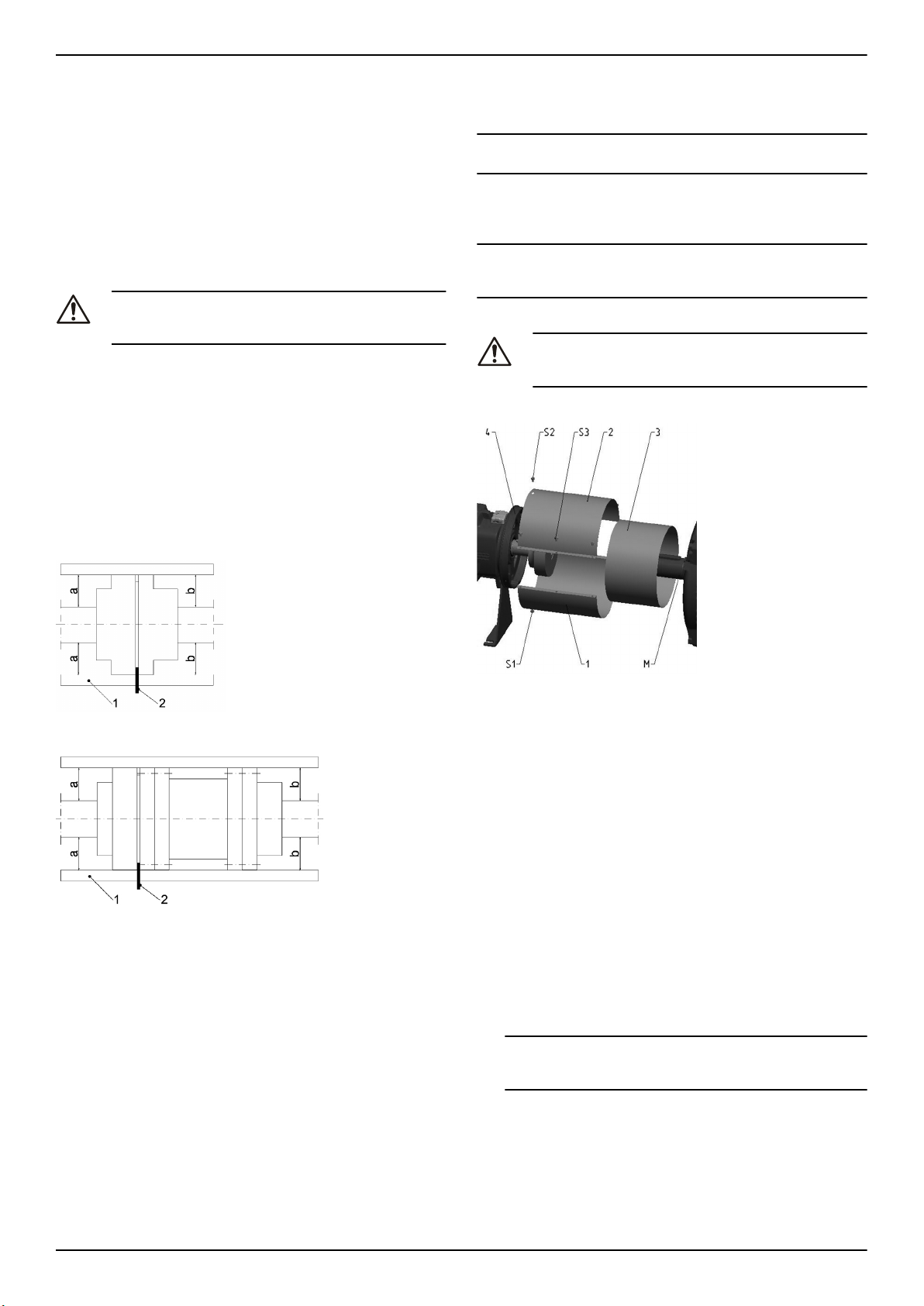
en - Translation of the original instructions
• Adequate space between pump and motor shaft must be left depending on the used coupling.
• Between pump and base frame must be an adequate shimming,
so that in case of replacement the same height between bottom
and centerline can be adjusted (recommended vertical adjustment 4-6 mm).
4.3.2 Piping checklist
Check that the following are adhered to:
• The suction lift line has been laid with a rising slope, at positive
suction head line with a downward slope towards the pump.
• The nominal diameters of the pipelines are at least equal to the
nominal diameters of the pump nozzles.
• The pipelines have been anchored in close proximity to the pump
and connected without transmitting any stresses or strains.
CAUTION:
Welding beads, scale and other impurities in the piping damage the pump.
• Free the piping from any impurities.
• If necessary, install a filter.
• Follow the “Permitted Forces and torques on the flanges", see
Figure 21 .
The data on forces and moments apply to static pipelines only. The
values are only applicable if the pump is installed on a baseplate and
bolted to a rigid and level foundation.
4.3.3 Coupling alignment
After mounting to the foundation and the connection of the piping, the
coupling must be adjusted again, even if the unit was delivered completely mounted on the frame.
Figure 4: Alignment of standard coupling
• The radial and axial deviation between the two coupling
halves must not exceed the values in table xyz, during
standstill as well as at operating temperature and under inlet
pressure.
NOTICE:
Mount coupling guard after alignment and before start-up.
Note: Control alignment of coupling again in operation warm condition
and on system pressure (if available) and correct, if necessary. Pay attention to chapter 6 beforehand! It must be possible to turn the unit
easily and harmoniously by hand.
NOTICE:
Improper alignment of the unit can lead to damages at coupling and
unit.
4.3.4 Install the coupling guard
CAUTION:
Never operate the pump without the coupling guard correctly
installed.
Figure 6: Coupling guard parts
Figure 5: Alignment of spacer coupling
1. Coupling guard upper half
2. Coupling guard lower half
3. Adjusting piece
Remove the coupling guard.
1. Loosen the support foot and re-tighten it without transmitting any
stresses and strains.
2. Place the ruler (1) axially on both coupling halves.
3. Leave the ruler (1) in this position and turn the coupling by hand.
• The coupling is aligned correctly if the distances a and b to
the respective shafts are the same at all points around the
circumference.
• The radial and axial deviation between the two coupling
halves must not exceed the values in table xyz, during
standstill as well as at operating temperature and under inlet
pressure.
4. Check the distance (dimension see general arrangement drawing) between the two coupling halves around the circumference
with a gauge (4). The coupling is correctly aligned if the distance
between the two coupling halves is the same at all points around
the circumference.
1. Coupling guard lower half
2. Coupling guard upper half
3. Adjusting half
1. Screw coupling guard lower half (1) with screws (S1)to bottom of
bearing cover (4) ring.
2. Insert adjusting piece (3) with slot downward and press it axially
to the motor.
3. Screw coupling guard upper half (1) with screws (S2) to the upper
side of the bearing cover (4) ring.
4. Screw parts 1 and 2 together, which fixes the adjusting piece.
4.3.5 Electrical installation
1. Remove the screws of the terminal box cover.
2. Connect and fasten the power cables according to the applicable
wiring diagram.
For wiring diagrams, see Figure 24 . The diagrams are also available on the back of the terminal box cover.
a) Connect the ground (earth) lead.
Make sure that the ground (earth) lead is longer than the
phase leads.
b) Connect the phase leads.
3. Mount the terminal box cover.
NOTICE:
Tighten the cable glands carefully to ensure protection against cable slipping and humidity entering the terminal box.
4. If the motor is not equipped with automatic reset thermal protection, then adjust the overload protection according to the list below.
e-NSC Installation, Operation, and Maintenance Manual 17
Page 18
en - Translation of the original instructions
• If the motor is used with full load, then set the value to the
nominal current value of electric pump (data plate)
• If the motor is used with partial load, then set the value to
the operating current (for example measured with a current
pincer).
• If the pump has a star-delta starting system, then adjust the
thermal relay to 58% of the nominal current or operating current (only for three-phase motors).
5 Commissioning, Startup, Operation, and Shutdown
Precautions
WARNING:
• Make sure that the drained liquid does not cause damage or injuries.
• The motor protectors can cause the motor to restart unexpectedly. This could result in serious injury.
• Never operate the pump without the coupling guard
correctly installed.
CAUTION:
• The outer surfaces of the pump and motor can exceed
40ºC (104ºF) during operation. Do not touch with any
part of the body without protective gear.
• Do not put any combustible material near the pump.
NOTICE:
• Never operate the pump below the minimum rated flow, when dry,
or without prime.
• Never operate the pump with the delivery ON-OFF valve closed
for longer than a few seconds.
• Never operate the pump with the suction ON-OFF valve closed.
• Do not expose an idle pump to freezing conditions. Drain all liquid
that is inside the pump. Failure to do so can cause liquid to freeze
and damage the pump.
• The sum of the pressure on the suction side (mains, gravity tank)
and the maximum pressure that is delivered by the pump must
not exceed the maximum working pressure that is allowed (nominal pressure PN) for the pump.
• Do not use the pump if cavitation occurs. Cavitation can damage
the internal components.
Noise level
For information about noise levels of pump alone and pump equipped
with standard supplied motor, see Table 10.
5.1 Fill the pump
For information about Additional pump connections, see Figure 25 .
Installations with liquid level above the pump (suction head)
For an illustration that shows the pump parts, see Figure 26 .
1. Close the on-off valve located downstream from the pump.
2. Remove the fill (3)or gauge plug (1) and open the on/off valve upstream until the water flows out of the hole.
a) Close the fill (3) or gauge plug (1).
Installations with liquid level below the pump (suction lift)
For an illustration that shows the pump parts, see Figure 27 .
1. All pipe system empty:
a) Open the on-off valve located upstream from the pump and
close the
b) Remove the fill plug (3) and the gauge plug (1) use a funnel
to fill the pump through the fill plug (3) until water flows out of
this hole.
c) Tighten the fill plug (3) and the gauge plug (1).
2. Filled discharge pipe system:
a) Open the on-off valve located upstream from the pump and
close the on-off valve downstream.
b) Remove the gauge plug (1) until water flows out of this hole.
c) Tighten the gauge plug (1).
5.2 Check the rotation direction (three-phase motor)
Follow this procedure before start-up.
1. Locate the arrows on the adaptor or the motor fan cover to determine the correct rotation direction.
2. Start the motor.
3. Quickly check the direction of rotation through the coupling guard
or through the motor fan cover.
4. Stop the motor.
5. If the rotation direction is incorrect, then do as follows:
a) Disconnect the power supply.
b) In the terminal board of the motor or in the electric control
panel, exchange the position of two of the three wires of the
supply cable.
For the wiring diagrams, see Figure 24 .
c) Check the direction of rotation again.
5.3 Start the pump
The responsibility for checking the correct flow and the temperature of
the pumped liquid rests with the installer or owner.
Before starting the pump, make sure that:
• The pump is correctly connected to the power supply.
• The pump is correctly filled according to instructions in Fill the
pump (chapter 5).
• The on-off valve located downstream from the pump is closed.
1. Start the motor.
2. Gradually open the on-off valve on the discharge side of the
pump.
At the expected operating conditions, the pump must run smoothly and quietly. If not, refer to Troubleshooting.
6 Maintenance
Precautions
Electrical Hazard:
Disconnect and lock out electrical power before installing or
servicing the unit.
WARNING:
• Maintenance and service must be performed by skilled
and qualified personnel only.
• Observe accident prevention regulations in force.
• Use suitable equipment and protection.
• Make sure that the drained liquid does not cause damage or injuries.
6.1 Service
If the user wishes to schedule regular maintenance deadlines, they are
dependent on the type of pumped liquid and on the operating conditions of the pump.
Contact the local sales and service representative for any requests or
information regarding routine maintenance or service.
Extraordinary maintenance may be necessary to clean the liquid end
and/or replace worn parts.
Bearing types
• Lubrication and lubricant change of rolling element bearings
• Grease-lubricated bearings
• Grease-lubricated bearings have been packed with grease
at the factory. See the bearing size and lubrication type in table 6.
Pumps with greased for life bearings
Pumps with greased for life bearings do not require any scheduled routine maintenance.
Pumps with re-greaseable bearings
• Regrease at 4000 operating hours, but at least once per year.
Clean lubrication nipples (SN) first.
• Use NLGI Grade 2 grease or equivalent.
• For approximate quantities of grease, see table 6.
6.2 Torque values
For information about torque values, pump data see Figure 28 , baseplate data Table 29 .
18 e-NSC Installation, Operation, and Maintenance Manual
Page 19
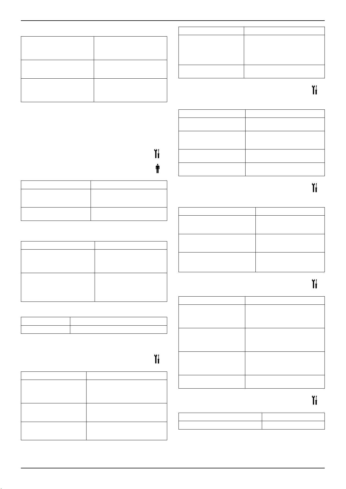
en - Translation of the original instructions
6.3 Inspection checklist
Check the coupling Check the flexible elements of the
Check the mechanical seal Check for leakage of the mechani-
Checking the bearing seals Check correct seating of axial seal
coupling. Replace the relevant
parts if there is any sign of wear
and check the alignment.
cal seal. Replace the mechanical
seal if leakage is found.
rings mounted on the shaft. Only
gentle contact of the sealing lip
shall be established.
6.4 Disassemble and replace the pump parts
For more information about spare parts and assembly and disassembly of the pump see Figure 1 , Figure 2 , Figure 3 , or Figure 4 .
See the Repair and Assembly Instructions which are available for
download from our homepage.
7 Troubleshooting
7.1 Troubleshooting for users
The main switch is on, but the electric pump does not start.
Cause Remedy
The thermal protector incorporated in the pump (if any) has
tripped.
The protective device against
dry running has tripped.
The electric pump starts, but the thermal protection trips a varying time
after.
Cause
There are foreign objects (solids or
fibrous substances) inside the
pump which have jammed the impeller.
The pump is overloaded because
it is pumping liquid that is too
dense and viscous.
The pump runs but delivers too little or no liquid.
Cause
The pump is clogged. Contact the Sales and Service Department.
The troubleshooting instructions in the tables below are for installers
only.
Remedy
7.2 The main switch is on, but the electric pump does not start
Cause
There is no power supply. • Restore the power supply.
The thermal protector incorporated in the pump (if any) has
tripped.
The thermal relay or motor
protector in the electric control
panel has tripped.
Wait until the pump has cooled
down. The thermal protector will automatically reset.
Check the liquid level in the tank, or
the mains pressure.
Remedy
Contact the Sales and Service
Department.
Check the actual power requirements based on the characteristics of the pumped liquid and then
contact the Sales and Service
Department.
Remedy
• Make sure all electrical connections to the power supply are intact.
Wait until the pump has cooled down.
The thermal protector will automatically reset.
Reset the thermal protection.
Cause Remedy
The protective device against
dry running has tripped.
The fuses for the pump or
auxiliary circuits are blown.
Check the:
• liquid level in the tank, or the
mains pressure
• protective device and its connecting cables
Replace the fuses.
7.3 The electric pump starts, but the thermal protector trips or the fuses blow immediately after
Cause Remedy
The power supply cable is
damaged.
The thermal protection or fuses
are not suited for the motor
current.
The electric motor is short circuit.
The motor overloads. Check the operating conditions of the
Check the cable and replace as necessary.
Check the components and replace
as necessary.
Check the components and replace
as necessary.
pump and reset the protection.
7.4 The electric pump starts, but the thermal protector trips or the fuses blow a short time after
Cause
The electrical panel is situated in an
excessively heated area or is exposed to direct sunlight.
The power supply voltage is not
within the working limits of the motor.
A power phase is missing. Check the
Remedy
Protect the electrical panel from
heat source and direct sunlight.
Check the operating conditions
of the motor.
• power supply
• electrical connection
7.5 The electric pump starts, but the thermal protector trips a varying time after
Cause
There are foreign objects (solids or fibrous substances) inside the pump which have jammed the impeller.
The pumps delivery rate is
higher than the limits specified
on the data plate.
The pump is overloaded because it is pumping liquid that
is too dense and viscous.
The motor bearings are worn. Contact the local sales and service
Remedy
Contact the local sales and service
representative.
Partially close the on-off valve down
stream until the delivery rate is equal
or less than the limits specified on
the data plate.
Check the actual power requirements
based on the characteristics of the
pumped liquid and replace the motor
accordingly.
representative.
7.6 The electric pump starts, but the system's general protection is activated
Cause
A short circuit in the electrical system. Check the electrical system.
Remedy
e-NSC Installation, Operation, and Maintenance Manual 19
Page 20
en - Translation of the original instructions
7.7 The electric pump starts, but the system's residual current device (RCD) is activated
Cause Remedy
There is an ground
(earth) leakage.
Check the insulation of the electrical system
components.
7.8 The pump runs but delivers too little or no liquid
Cause Remedy
There is air inside the
pump or the piping.
The pump is not correctly
primed.
The throttling on the delivery side is too extensive.
Valves are locked in closed
or partially closed position.
The pump is clogged. Contact the local sales and service repre-
The piping is clogged. Check and clean the pipes.
The rotation direction of
the impeller is wrong
(three-phase version)
.
The suction lift is too high
or the flow resistance in
the suction pipes is too
great.
• Bleed the air
Stop the pump and repeat the prime procedure.
If the problem continues:
• Check that the mechanical seal is
not leaking.
• Check the suction pipe for perfect
tightness.
• Replace any valves that are leaking.
Open the valve.
Disassemble and clean the valves.
sentative.
Change the position of two of the phases
on the terminal board of the motor or in
the electric control panel.
Check the operating conditions of the
pump. If necessary, do the following:
• Decrease the suction lift
• Increase the diameter of the suction
pipe
Cause Remedy
The motor bearings are worn.
There are foreign
objects inside the
pump.
For any other situation, refer to the local sales and service representative.
Contact the local sales and service representative.
Contact the local sales and service representative.
7.9 The electric pump stops, and then rotates in the wrong direction
Cause
There is a leakage in one or both of the following components:
• The suction pipe
• The foot valve or the check valve
There is air in the suction pipe. Bleed the air.
Remedy
Repair or replace the
faulty component.
7.10 The pump starts up too frequently
Cause
There is a leakage in one or both of the following components:
• The suction pipe
• The foot valve or the check valve
There is a ruptured membrane or no air
pre-charge in the pressure tank.
Remedy
Repair or replace the
faulty component.
See the relevant instructions in the pressure
tank manual.
7.11 The pump vibrates and generates too much noise
Cause
Pump cavitation Reduce the required flow rate by partially closing
Remedy
the on-off valve downstream from the pump. If the
problem persists check the operating conditions of
the pump (for example height difference, flow resistance, liquid temperature).
20 e-NSC Installation, Operation, and Maintenance Manual
Page 21
fr - Traduction des instructions d'origine
1 Introduction et sécurité
1.1 Introduction
Objet de ce manuel
L'objet de ce manuel est d'apporter les informations nécessaires pour :
• L'installation
• L'utilisation
• La maintenance
ATTENTION :
Lire attentivement ce manuel avant d'installer et d'utiliser ce
produit. Une mauvaise utilisation du produit peut entraîner
des blessures et des dégâts matériels et pourrait annuler la
garantie.
REMARQUE :
Conserver ce manuel pour une consultation ultérieure et veiller à ce
qu'il puisse facilement être consulté sur le site à tout moment.
1.1.1 Utilisateurs sans expérience
AVERTISSEMENT :
Ce produit est destiné à être utilisé par du personnel qualifié
exclusivement.
Respecter les précautions ci-dessous :
• Les personnes à mobilité réduite ne doivent pas être autorisées à
utiliser le produit sans supervision ou formation appropriée par un
professionnel.
• Les enfants doivent faire l'objet d'une surveillance permettant de
s'assurer qu'ils ne peuvent pas jouer sur ou autour du produit.
1.2 Terminologie et symboles de sécurité
A propos des messages de sécurité
Il est extrêmement important de lire, comprendre et respecter attentivement les consignes de sécurité et la réglementation avant d'utiliser
ce produit Xylem. Ces consignes sont publiées pour contribuer à la
prévention des risques suivants :
• accidents corporels et mise en danger de la santé
• Dégâts matériels
• Dysfonctionnement du produit
Niveaux de risque
Niveau de risque
DANGER :
AVERTISSEMENT :
ATTENTION :
REMARQUE :
Catégories de risques
Soit les risques correspondent aux catégories habituelles, soit il faut
utiliser des symboles spéciaux pour les représenter.
Les risques de choc électrique sont indiqués par le symbole spécifique
suivant :
RISQUE DE CHOC ÉLECTRIQUE :
Voici des exemples d'autres catégories éventuelles. Elles se classent
en dessous des niveaux de risque ordinaires et peuvent utiliser des
symboles complémentaires :
• Risque d'écrasement
Indication
Une situation dangereuse qui, si
elle n'est pas évitée, entraînera la
mort ou des blessures graves
Une situation dangereuse qui, si
elle n'est pas évitée, peut entraîner la mort ou des blessures graves
Une situation dangereuse qui, si
elle n'est pas évitée, peut entraîner des blessures mineures ou légères
• Une situation potentiellement
dangereuse qui, si elle n'est
pas évitée, peut conduire à
des conditions non désirées
• Une pratique n'entraînant
pas de blessure corporelle
• Risque de coupure
• Risque d'arc électrique
Risque de surface chaude
Les risques de surface chaude sont signalés par un symbole spécifique qui remplace les symboles courants de niveau de risque :
ATTENTION :
Description des symboles pour l'utilisateur et l'installateur
Informations spécifiques pour les personnes chargées
de l'installation du produit dans le circuit (plomberie hydraulique ou câblage électrique) ou chargées de l'entretien.
Informations spécifiques pour les utilisateurs du produit
Mode opératoire
Les instructions et avertissements de ce manuel concernent la version
standard, décrite dans le document commercial. Les pompes de version spéciales peuvent être fournies avec des fiches d'instruction supplémentaires. Consulter le contrat de vente pour toutes modifications
ou caractéristiques de version spéciales. Pour des instructions, situations ou événements non pris en compte dans ce manuel ou dans le
document commercial, contacter le Centre de réparation Lowara le
plus proche.
1.3 Élimination des emballages et du produit
Respecter les codes électriques et réglementations locales applicables
pour l'élimination des déchets.
1.4 Garantie
Pour plus d'informations sur la garantie, voir le contrat de vente.
1.5 Pièces de rechange
AVERTISSEMENT :
N'utiliser que des pièces de rechange d'origine pour remplacer les pièces usées ou défectueuses. L'utilisation de pièces
de rechange inadéquates peut entraîner un mauvais fonctionnement, des dégâts matériels, des blessures et annuler
la garantie.
ATTENTION :
Toujours spécifier le type exact du produit et la référence de
la pièce pour toute demande d'informations techniques ou
de pièces de rechange auprès du Service commercial et
après-vente.
Pour plus d'informations sur les pièces de rechange des produits, voir
Figure 1, Figure 2, Figure 3 ou Figure 4
1.6 DÉCLARATION DE CONFORMITÉ CE
XYLEM SERVICE ITALIA SRL, DONT LE SIÈGE SOCIAL SE TROUVE À VIA VITTORIO LOMBARDI 14 - 36075 MONTECCHIO MAGGIORE VI - ITALIA, DÉCLARE QUE LE PRODUIT SUIVANT :
GROUPE DE POMPAGE ÉLECTRIQUE (VOIR ÉTIQUETTE EN PREMIÈRE PAGE)
EST CONFORME AUX CLAUSES APPLICABLES DES DIRECTIVES
EUROPÉENNES SUIVANTES :
• DIRECTIVE MACHINES 2006/42/CE (LE DOSSIER TECHNIQUE EST DISPONIBLE AUPRÈS DE XYLEM SERVICE ITALIA
SRL).
• COMPATIBILITÉ ÉLECTROMAGNÉTIQUE 2004/108/CE
• ECO-DESIGN 2009/125/CE, RÈGLEMENT (CE) N° 547/2012,
RÈGLEMENT (CE) 640/2009 (3 ~, 50 Hz, PN≥ 0,75 kW) POUR
MARQUAGE IE2 ou IE3
ET LES NORMES TECHNIQUES SUIVANTES
• EN 809, EN 60335-1, EN 60335-2-41, EN 62233
• EN 61000-6-1:2007, EN 61000-6-3:2007
• EN 60034–30
• EN 953 :1997+A1:2009
• EN ISO 12100 :2010
• EN 60204-1 :2006/A1:2009
LA POMPE (VOIR ÉTIQUETTE EN PREMIÈRE PAGE)
e-NSC Installation, Operation, and Maintenance Manual 21
Page 22
fr - Traduction des instructions d'origine
EST CONFORME AUX CLAUSES APPLICABLES DES DIRECTIVES
EUROPÉENNES SUIVANTES
• MACHINES 2006/42/CE (LE DOSSIER TECHNIQUE EST DISPONIBLE AUPRÈS DE XYLEM SERVICE ITALIA SRL).
ET AUX NORMES TECHNIQUES SUIVANTES:
• EN 809
• EN 953 :1997+A1:2009
• EN ISO 12100 :2010
MONTECCHIO MAGGIORE,
XX.04.2014
AMEDEO VALENTE
(DIRECTEUR INGÉNIERIE ET R&D)
rév.01
Lowara est une marque commerciale de Xylem Service Italia S.R.L., filiale de Xylem Inc.
2 Transport et stockage
2.1 Contrôle lors de la livraison
1. Rechercher des traces de dégâts visibles sur l'extérieur de l'emballage.
2. Avertir notre distributeur dans les huit jours de la date de livraison
si le produit présente des traces de dégâts visibles.
Déballage du groupe
1. Suivre l'opération applicable :
• Si le groupe est emballé dans un carton, déposer les agrafes et ouvrir le carton.
• Si le groupe est emballé dans une caisse en bois, ouvrir le
couvercle en prenant garde aux sangles et aux clous.
2. Déposer les vis de fixation ou les sangles du socle en bois.
2.1.1 Contrôle du groupe
1. Enlever l'emballage de l'équipement.
Évacuer tous les matériaux d'emballage conformément à la légis-
lation locale.
2. Contrôler l'équipement afin d'établir si des pièces sont endommagées ou manquantes.
3. Le cas échéant, détacher l'équipement en enlevant toute vis, boulon ou sangle.
Pour votre sécurité, manipuler les clous et les sangles avec précaution.
4. Contacter le représentant commercial local pour toute question.
2.2 Directives pour le transport
Précautions
AVERTISSEMENT :
• Respecter les règlements en vigueur concernant la prévention des accidents.
• Risque d'écrasement. Le groupe et ses éléments peuvent être lourds. Employer les méthodes de levage appropriées et porter en permanence des chaussures de
sécurité.
Vérifier le poids brut indiqué sur le carton pour sélectionner l'équipement de levage approprié.
• Pour déplacer le groupe motopompe seulement, utiliser des sangles bien fixées sur l'adaptateur de moteur.
La pompe, le groupe motopompe ou l'ensemble arrière doit toujours
être fixé et transporté comme indiqué sur les Figure 5, Figure 6, Figure
7 et Figure 8.
Groupe sans moteur
AVERTISSEMENT :
Une pompe et un moteur achetés séparément pour accouplement ultérieur constituent une nouvelle machine au sens
de la directive machine 2006/42/CE. La personne qui effectue l'accouplement est responsable de tous les aspects de
sécurité du groupe combiné.
2.3 Conseils pour l'entreposage
Lieu de stockage
Le produit doit être stocké dans un lieu couvert et sec, exempt de
source de chaleur, de saleté et de vibrations.
REMARQUE :
• Protéger le produit contre l'humidité, les sources de chaleur et les
dommages mécaniques.
• Ne pas poser d'objets lourds sur le produit emballé.
2.3.1 Stockage longue durée
Si le groupe doit être stocké plus de 6 mois, les exigences suivantes
doivent être respectées :
• Stocker dans un endroit abrité et sec.
• Stocker le groupe à l'abri de la chaleur, de la saleté et des vibrations.
• Faire tourner l'arbre de pompe à la main plusieurs fois au moins
tous les trois mois.
Traiter les roulements et les surfaces usinées pour assurer une bonne
protection. Consulter les fabricants de l'ensemble d'entraînement et
des accouplements pour la marche à suivre en cas de stockage de
longue durée.
Pour toute question sur les services de traitement possibles pour le
stockage à long terme, contacter votre représentant commercial et
après-vente local.
Température ambiante
Le produit doit être stocké à température ambiante de -5°C à +40°C
(23°F à 104°F).
3 Descriptif du produit
3.1 Conception de la pompe
La pompe est du type horizontal à un seul étage et support roulement
avec corps en volute accouplé à des moteurs électriques standard. La
pompe peut être utilisée pour le traitement de :
• Eau chaude ou froide
• Liquides propres
• Liquides agressifs mais sans agressivité chimique ni mécanique
pour les matériaux de la pompe.
Le produit peut être fourni sous forme de groupe de pompage (pompe
et moteur électrique) ou sous forme de pompe seule.
REMARQUE :
Si vous avez acheté une pompe sans moteur, s'assurer que le moteur
est conçu pour accouplement à la pompe.
Position et fixation
La pompe ou le groupe motopompe ne peut être transporté que horizontalement. S'assurer que la pompe ou le groupe motopompe est fixé
de façon sûre pour le transport, qu'il ne peut ni rouler ni basculer.
AVERTISSEMENT :
Ne pas utiliser de pitons à œil vissés sur le moteur pour la
manutention du groupe motopompe électrique complet.
Ne pas utiliser le bout d'arbre de la pompe ou du moteur
pour la manutention de la pompe, du moteur ou du groupe.
• Les pitons à œil visés sur le moteur peuvent être utilisés exclusivement pour la manutention du moteur seul, ou en cas de distribution inégale des charges, pour le levage partiel du groupe à la
verticale à partir d'un déplacement horizontal.
Usage prévu
La pompe convient pour :
• Fourniture et traitement de l'eau
• Fourniture d'eau de refroidissement et d'eau chaude dans les services industriels et de bâtiment
• Systèmes de filtre, etc.
• Systèmes d'irrigation et d'arrosage
• Systèmes d'évacuation
• Systèmes de chauffage
• Transport de condensats
• Applications de lutte contre l'incendie
Usages supplémentaires pour les matériels en option :
22 e-NSC Installation, Operation, and Maintenance Manual
Page 23
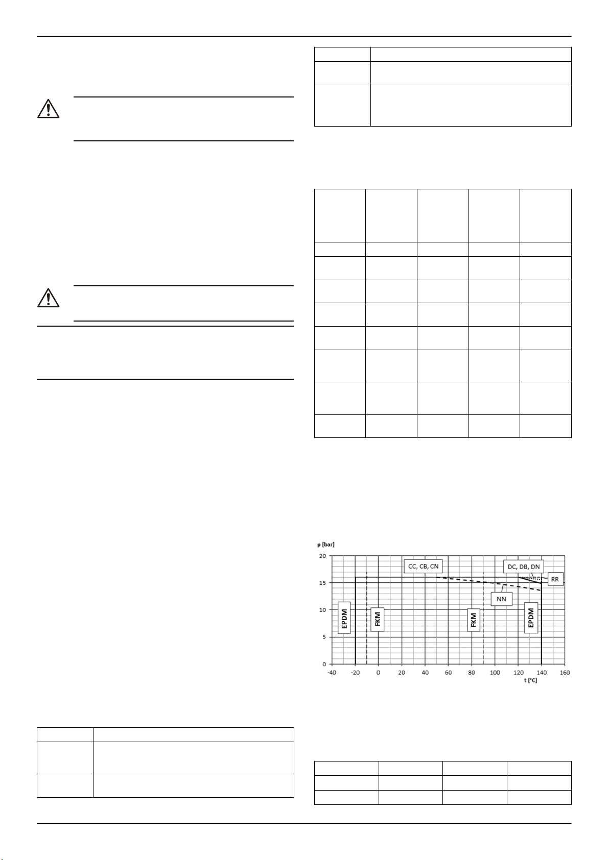
fr - Traduction des instructions d'origine
• Chauffage urbain
• Industrie en général
• Industrie alimentaire et de boissons
Usage non conforme
AVERTISSEMENT :
Une utilisation incorrecte de la pompe peut provoquer des
situations dangereuses et occasionner des blessures corporelles ou des dégâts matériels.
Une utilisation incorrecte du produit conduit à la perte de la garantie.
Exemples d'utilisation incorrecte :
• Liquides non compatibles avec les matériaux de construction de
la pompe
• Liquides dangereux (par exemple toxiques, explosifs, inflammables ou corrosifs)
• Liquides potables autre que l'eau (par exemple vin ou lait)
Exemples d'installation incorrecte :
• Emplacements dangereux (par exemple atmosphères explosives
ou corrosives).
• Emplacement où la température de l'air est très élevée ou la ventilation insuffisante.
• Installations à l'extérieur en l'absence de protection contre la pluie
ou le gel.
DANGER :
Ne pas utiliser cette pompe pour pomper des liquides inflammables et/ou explosibles.
REMARQUE :
• Ne pas utiliser cette pompe pour pomper des liquides contenant
des substances abrasives, solides ou fibreuses.
• Ne pas utiliser la pompe pour des débits dépassant ceux mentionnés sur la plaque signalétique.
Applications spéciales
Contacter le service après-vente local dans les cas suivants :
• Si la densité et/ou la viscosité du liquide pompé dépasse celle de
l'eau, par exemple eau avec glycol, un moteur plus puissant peut
être nécessaire.
• Si le liquide pompé est traité chimiquement (par exemple adouci,
désionisé, déminéralisé, etc.).
• Pour toute situation différente de celles décrites et dépendant de
la nature du liquide.
3.2 Description de la pompe
Voir Figure 9 pour une explication du code de description de la pompe
et un exemple.
3.3 Plaque signalétique
La plaque signalétique est une étiquette métallique située sur le support roulement. La plaque signalétique regroupe les caractéristiques
principales du produit. Pour toute information complémentaire, voir Fi-
gure 10 et Figure 11.
La plaque signalétique donne des informations sur le matériau de la
roue et du corps, le joint mécanique et les matériaux correspondants.
Pour plus d'informations, voir Figure 12.
Pièce Descriptif
Joint d'arbre • Joint mécanique unique selon EN 12756
Roulements • Roulements à billes radiaux
Voir le plan en coupe Figure 13.
• Joint mécanique à cartouche en option
• Lubrification à la graisse
• En option : lubrification à l'huile (support roulement avancé)
3.5 Matériau
Les parties métalliques de la pompe entrant en contact avec l'eau sont
dans un des métaux suivants :
Standard /
En option
Standard CC Fonte/fonte X
Standard CB Fonte/bron-
Standard CN Fonte/acier
Standard DC Fonte ducti-
Standard DB Fonte ducti-
Standard DN Fonte ducti-
Standard NN Acier inoxy-
En option RR Duplex / Du-
Code de
matériau
Matériau de
corps/roue
ze
inoxydable
le/fonte
le/bronze
le/acier ino-
xydable
dable/acier
inoxydable
plex
Gamme
EN733
32–125 à
150-400
X
X
X
X X
Gamme à
rallonge
125-500,
150-500 à
300-450
X
X
X
3.6 Joint mécanique
Joint mécanique unique déséquilibré selon EN 12756, dimensions version K. Voir Tableau 1.
3.7 Limites d'application
Pression de service maximale
Ce diagramme donne la pression maximale d'utilisation en fonction du
modèle de pompe et de la température du liquide pompé.
Marquages IMQ ou TUV, IRAM ou autres (pour pompe électrique
seulement)
Sauf spécification contraire, pour les produits portant un marquage
d'homologation, l'homologation ne concerne que la pompe électrique.
3.4 Structure de conception
• Dimensions selon EN 733 et dimensions de rallonge supplémentaire non standardisée
• Pompe à corps en volute et support roulement à extraction par
l'arrière ou à arbre de liaison
• Étage unique
• Pour montage horizontal
Pièce
Corps • Corps de volute à plan de joint radial et refoule-
Roue • Roue radiale fermée avec bagues d'usure des
Descriptif
ment radial
• Bague d'usure remplaçable
deux côtés
e-NSC Installation, Operation, and Maintenance Manual 23
P
+ P
1max
P
1max
P
max
PN Pression maximale de fonctionnement
Intervalles de température de liquide
Version
Standard EPDM -20°C (-4°F) 140°C (284°F)
En option FPM (FKM) -10 °C (14 °F) 90 °C (194 °F)
≤ PN
max
Pression d'entrée maximale
Pression maximale générée par la pompe
Joint Minimum Maximum
Page 24
fr - Traduction des instructions d'origine
Pour des exigences spécifiques, prendre contact avec le Service commercial et après-vente.
Nombre max. de démarrages par heure
Ce tableau donne le nombre maximal de démarrages autorisés par
heure pour les moteurs fournis par Lowara :
kW 0,25 -
Démarrages
par
heure
REMARQUE :
Si vous utilisez un moteur autre que celui qui vous a été fourni avec la
pompe électrique, vérifier les instructions correspondantes pour déterminer le nombre de démarrages autorisés par heure.
Niveau sonore
Voir les niveaux de pression acoustique sur la surface de mesure L
dans le Tableau 2.
4,00 -
3,00
60 40 25 16 8 4 3
11 - 22 30 - 37 45 - 75 90 –
7,50
160
185 -
355
pA
4 Installation
Précautions
AVERTISSEMENT :
• Respecter les règlements en vigueur concernant la prévention des accidents.
• Utiliser des équipements de protection adéquats.
• Se conformer systématiquement aux règlements locaux
ou nationaux, à la législation et aux codes en vigueur
concernant le choix du site d'installation et les raccordements de plomberie et en énergie.
RISQUE DE CHOC ÉLECTRIQUE :
• S'assurer que toutes les connexions sont effectuées
par des techniciens qualifiés et qu'elles sont conformes
aux réglementations en vigueur.
• Avant toute intervention sur le groupe, s'assurer que le
groupe et le panneau de commande ne sont pas alimentés et ne risquent pas d’être remis sous tension.
Cette consigne s'applique également au circuit de commande.
Mise à la terre (masse)
RISQUE DE CHOC ÉLECTRIQUE :
• Toujours relier le conducteur de protection externe à la
borne de terre (masse) avant d'effectuer les autres
branchements électriques.
• Vous devez correctement mettre à la terre (masse) tous
les équipements électriques. Ceci s'applique à l'équipement de pompe, à l'entraînement, comme à l'équipement de surveillance. Tester le conducteur de terre
(masse) pour vérifier qu'il est correctement connecté.
• Si le câble de moteur est arraché de la prise par erreur,
le conducteur de terre (masse) doit être le dernier à se
décrocher de sa borne. Vérifier que le fil de terre (masse) est plus long que les fils de phase. Ceci s'applique
aux deux extrémités du câble de moteur.
• Ajouter une protection supplémentaire contre les électrocutions mortelles. Poser un interrupteur différentiel à
haute sensibilité (30 mA) [RCD : residual current device].
4.1 Exigences d'installation
4.1.1 Emplacement de la pompe
DANGER :
Ne pas utiliser ce groupe dans des environnements qui peuvent contenir des gaz inflammables/explosifs ou chimiquement agressifs ou des poudres.
Conseils
Respecter les règles suivantes concernant l'emplacement du produit :
• S'assurer qu'aucune obstruction n'empêche le débit normal d'air
de refroidissement fourni par le ventilateur du moteur.
• S'assurer que la zone d'installation est protégée contre toute fuite
de liquide ou inondation.
• Si possible, placer la pompe légèrement au-dessus du niveau du
sol.
• La température ambiante doit être comprise entre 0°C (+32°F) et
+40°C (+104°F).
• L'humidité relative de l'air ambiant doit être inférieure à 50 % à
+40 °C (+104 °F).
• Prenez contact avec le Service commercial et après-vente si :
• L'humidité relative de l'air dépasse les valeurs indiquées.
• La température ambiante dépasse +40 °C (+104 °F).
• Le groupe est situé à plus de 1000 m (3000 pi) au-dessus
du niveau de la mer. Les performances du moteur peuvent
en être réduites ou nécessiter un remplacement par un moteur plus puissant.
Pour plus d'information sur les valeurs de dégradation des performances du moteur, voir Tableau 3.
Positions de la pompe et dégagement
Fournir un éclairage et un dégagement suffisant autour de la pompe.
S'assurer qu'elle est facilement accessible pour les opérations d'installation et d'entretien.
Installation au-dessus de la source de liquide (levage d'aspiration)
La hauteur maximale d'aspiration théorique pour n'importe quel type
de pompe est de 10,33 m. En pratique, les facteurs suivants peuvent
réduire la capacité d'aspiration de la pompe :
• Température du liquide
• Altitude au-dessus du niveau de la mer (en circuit ouvert)
• Pression dans le circuit (en circuit fermé)
• Perte de charge des canalisations
• Perte de charge interne de la pompe
• Différences de hauteur
L'équation ci-dessous permet de calculer la hauteur maximale au-dessus du niveau de liquide à laquelle la pompe peut être installée:
(pb*10,2 - Z) ≥ NPSH + Hf + Hv + 0,5
p
Pression barométrique en bars, (pression du circuit pour un
b
circuit fermé)
NPSH Valeur en mètres de la perte de charge interne de la pompe
H
Pertes totales en mètres causées par le passage du liquide
f
dans la canalisation d'aspiration de la pompe
H
Pression de vapeur en mètres correspondant à la température
v
du liquide T °C
0,5 Marge de sécurité recommandée (m)
Z Hauteur maximale à laquelle la pompe peut être installée (m)
Pour plus d'informations, voir Figure 14.
(pb*10,2 - Z) doit toujours être positif.
REMARQUE :
Ne pas dépasser la capacité d'aspiration de la pompe, car ceci peut
occasionner une cavitation et endommager la pompe.
4.1.2 Exigences de canalisations
Précautions
AVERTISSEMENT :
• Utiliser des canalisations qui correspondent à la pression de fonctionnement maximale de la pompe. Le nonrespect de cette consigne peut amener une rupture du
système et en conséquence occasionner des risques
de blessure.
• S'assurer que toutes les connexions sont effectuées
par des techniciens qualifiés et qu'elles sont conformes
aux réglementations en vigueur.
REMARQUE :
Respecter toutes les réglementations des autorités compétentes et
des sociétés de gestion du service public de l'eau si la pompe est reliée à un réseau public d'alimentation en eau. Si nécessaire, installer
un dispositif antiretour approprié à l'aspiration.
Liste de contrôle des canalisations
Vérifier que les conditions suivantes sont respectées :
24 e-NSC Installation, Operation, and Maintenance Manual
Page 25

fr - Traduction des instructions d'origine
• Toutes les canalisations sont soutenues indépendamment, les canalisations ne doivent exercer aucune contrainte sur le groupe.
• Des canalisations ou raccords souples doivent être utilisés pour
éviter la transmission des vibrations de la pompe aux canalisations et inversement.
• Utiliser des coudes à grand rayon, éviter l'utilisation de coudes
qui causeraient une trop grande résistance au passage.
• Les canalisations d'aspiration doivent être parfaitement jointives
et étanches à l'air.
• En cas d'utilisation de la pompe en circuit ouvert, le diamètre de
la canalisation d'aspiration doit être adapté aux conditions d'installation. La canalisation d'aspiration ne doit pas être de diamètre
inférieur à celui de l'orifice d'aspiration.
• Si la canalisation d'aspiration doit être de dimension supérieure
au côté aspiration de la pompe, un réducteur excentrique de canalisation doit être installé.
• Si la pompe est située au-dessus du niveau du liquide, un clapet
de pied doit être installé à l'extrémité de la canalisation d'aspiration.
• Le clapet de pied doit être totalement immergé dans le liquide
pour éviter toute pénétration d'air par le tourbillon d'aspiration,
quand le liquide se trouve au niveau minimal et que la pompe est
installée au-dessus de la source de liquide.
• Des vannes d'arrêt de dimension appropriée doivent être posées
sur les canalisations d'aspiration et de sortie (en aval du clapet)
pour assurer la régulation du débit de la pompe, son contrôle et
son entretien.
• Des vannes d'arrêt de dimension appropriée doivent être posées
sur la canalisation de sortie (en aval du clapet) pour assurer la régulation du débit de la pompe, son contrôle et son entretien.
• Un clapet antiretour doit être installé dans la canalisation de sortie
pour éviter tout débit inverse dans la pompe à l'arrêt de celle-ci.
AVERTISSEMENT :
Ne pas utiliser la vanne d'arrêt côté refoulement pour réguler
le débit de la pompe pendant plus de quelques secondes. Si
la pompe doit fonctionner plus de quelques secondes sur un
refoulement fermé, un circuit de dérivation doit être installé
pour éviter une surchauffe du liquide à l'intérieur de la pompe.
Pour des illustrations présentant les exigences de canalisation, voir Fi-
gure 15 et Figure 16.
4.2 Caractéristiques électriques
• Les réglementations locales applicables ont priorité sur ces préconisations.
• Pour les systèmes de lutte contre l'incendie (bouches d'incendie
ou systèmes d'arrosage), consulter les réglementations locales
en vigueur.
Liste de vérification des branchements électriques
Vérifier que les conditions suivantes sont respectées :
• Les fils électriques sont protégés contre les hautes températures,
les vibrations et les collisions.
• La ligne d'alimentation est équipée de :
• Un dispositif de protection contre les courts-circuits
• Un dispositif d'isolement du secteur avec écartement des
contacts d'au moins 3 mm
Liste de contrôle du tableau électrique de commande
REMARQUE :
Le tableau électrique de commande doit correspondre aux valeurs nominales de la pompe électrique. Des combinaisons incorrectes pourraient ne pas assurer une protection efficace du moteur.
Vérifier que les conditions suivantes sont respectées :
• Le tableau de commande doit protéger le moteur contre la surcharge et les courts-circuits.
• Installer une protection correcte contre les surcharges (relais thermique ou protecteur de moteur).
Type de pompe
Pompe électrique standard monophasée ≤ 1,5 kW
Protection
• Protection thermique-ampèremétrique intégrée à
réinitialisation automatique
(protection du moteur)
• Protection contre le court-
Pompe électrique triphasée et
autres pompes monophasées
circuit (doit être fournie
par l'installateur)
• Protection thermique (doit
6
être fournie par l'installa-
5
teur)
• Protection contre le courtcircuit (doit être fournie
par l'installateur)
• Le tableau de commande doit être équipé d'un système de protection contre le fonctionnement à sec relié à un manomètre, un
interrupteur à flotteur, des sondes ou autres dispositifs adaptés.
• Les équipements ci-dessous sont recommandés pour le côté aspiration de la pompe :
• Quand le liquide est pompé depuis un circuit d'eau, utiliser
un manocontact.
• Quand le liquide est pompé dans un réservoir ou un bassin
de stockage, utiliser un interrupteur à flotteur ou des sondes.
• En cas d'utilisation de relais thermiques, il est recommandé d'utiliser des relais sensibles à la défaillance d'une phase.
Liste de contrôle du moteur
AVERTISSEMENT :
• Lire les instructions d'utilisation pour vérifier si un dispositif de protection est prévu en cas d'utilisation d'un autre moteur que celui de série.
• Si le moteur est équipé de protecteurs thermiques automatiques, attention aux risques de démarrages inattendus associés à une surcharge. Ne pas utiliser de tels
moteurs dans la lutte contre les incendies et les systèmes d'arrosage d'incendie.
REMARQUE :
• N'utiliser que des moteurs équilibrés dynamiquement avec une
demi-clavette dans la rallonge d'arbre (IEC 60034-14) avec un
taux de vibration normal (N).
• La tension et la fréquence du moteur doivent correspondre aux
indications de la plaque signalétique du moteur.
• Utiliser uniquement des moteurs monophasés ou triphasés dont
la taille et la puissance sont conformes aux normes européennes.
En général, les moteurs peuvent fonctionner dans les tolérances de
tension secteur suivantes :
Fréquence en Hz
Phase ~ UN [V] ± %
50 1 220 – 240 ± 6
3 230/400 ± 10
400/690 ± 10
60 1 220 – 230 ± 6
3 220/380 ± 5
380/660 ± 10
Utiliser un câble conforme aux réglementations, à 3 conducteurs (2 +
terre/masse) pour les versions monophasées et 4 conducteurs (3 +
terre/masse) pour la version triphasée.
4.3 Installation de la pompe
4.3.1 Installation mécanique
Vérifier les points suivants avant l'installation :
• Utiliser un béton de classe de résistance à la compression
C12/15 conforme aux exigences de la classe d'exposition XC1
selon EN 206-1.
• La surface de montage doit avoir durci et être complètement horizontale et régulière.
• Respecter les poids indiqués.
5
fusibles aM (démarrage de moteur), ou interrupteur magnétothermique de courbe C et Icn ≥ 4,5 kA ou autre dispositif équivalent.
6
Relais thermique de surcharge de classe de fonctionnement 10 A + fusibles aM (démarrage de moteur) ou interrupteur magnétothermique de protection de moteur de classe de fonctionnement 10 A.
e-NSC Installation, Operation, and Maintenance Manual 25
Page 26

fr - Traduction des instructions d'origine
Montage du groupe sur une fondation
Pour des informations sur le socle et les trous d'ancrage de la pompe,
voir Figure 17.
Vérifier que la fondation a été préparée selon les dimensions données
dans le plan de disposition général ou d'implantation.
1. Positionner le groupe motopompe sur la fondation et le mettre à
niveau à l'aide d'un niveau à bulle placé sur l'arbre et sur la buse
de refoulement.
L'écart autorisé est de 0,2 mm/m.
2. Déposer les bouchons sur les orifices.
3. Aligner les brides de la pompe et des canalisations des deux côtés de la pompe. Vérifier l'alignement des vis.
4. Fixer les canalisations à la pompe à l'aide des vis. Ne pas forcer
pour mettre en place les canalisations.
5. Utiliser des cales (2) pour la compensation de hauteur si nécessaire.
Toujours poser les cales si nécessaire immédiatement sous les
vis de fondation de gauche et de droite (3) entre la plaque de socle/cadre de fondation et la fondation. Pour une distance entre vis
(L) > 800 mm, poser des cales supplémentaires (2) au milieu des
trous de vis.
6. S'assurer que toutes les cales sont parfaitement affleurantes.
7. Insérer les vis de fondation (3) dans les trous prévus.
8. Sceller les vis de fondation (3) dans la fondation avec du béton.
9. Attendre le durcissement du béton puis mettre à niveau la plaque
de socle.
10. Serrer les vis de fondation (3) à fond et régulièrement.
Remarque :
• Pour les plaques de socle, il est recommandé de sceller la plaque
de socle avec un mortier à faible retrait.
• Si la transmission de vibrations peut créer des perturbations, prévoir des supports d'amortissement des vibrations entre la pompe
et la fondation.
Montage de la pompe sur un cadre socle
S'assurer de vérifier que les points suivants sont respectés :
• Cadre socle solide ne risquant pas de vibrer ni de se déformer en
fonctionnement (résonance).
• Les faces d'appui des pieds de la pompe et du moteur sur le cadre socle doivent être planes (usinage recommandé).
• Une fixation sûre de la pompe et du moteur doit être assurée.
• Un espace suffisant doit être réservé entre la pompe et l'arbre du
moteur, selon le type d'accouplement utilisé.
• Un calage adéquat doit être prévu entre la pompe et le cadre socle, de façon à permettre le réglage à la même hauteur entre le
bas et l'axe pour remplacement (réglage vertical recommandé
4-6 mm).
4.3.2 Liste de contrôle des canalisations
Vérifier le respect des points suivants :
• La conduite avec levage d'aspiration a été mise en place avec
une pente montante, une conduite à pression d'aspiration positive
avec une pente descendante vers la pompe.
• Les diamètres nominaux des canalisations sont au moins égaux
aux diamètres nominaux des buses de la pompe.
• Les canalisations ont été ancrées au plus près de la pompe et
raccordées sans transmettre aucune contrainte ni déformation.
ATTENTION :
Les perles de soudure, le tartre et autres impuretés dans les
canalisations peuvent endommager la pompe.
• Dégager les canalisations de toutes leurs impuretés.
• Si nécessaire, installer un filtre.
• Respecter les « Forces et couples autorisés sur les brides », voir
Figure 18.
Les données concernant les forces et moments ne s'appliquent qu'aux
canalisations statiques. Les valeurs ne sont applicables que si la pompe est installée sur une plaque de socle vissée sur une fondation rigide
et de niveau.
4.3.3 Alignement de l'accouplement
Après montage sur la fondation et raccordement des canalisations,
l'accouplement doit être réglé à nouveau, même si le groupe a été livré
complètement monté sur le châssis.
Figure 7 : Alignement d'accouplement standard
Figure 8 : Alignement d'accouplement à entretoise
1. Demi-protecteur d'accouplement supérieur
2. Demi-protecteur d'accouplement inférieur
3. Élément de réglage
Déposer le protecteur d'accouplement.
1. Desserrer le pied support pour le resserrer sans contrainte ni déformation.
2. Placer la règle (1) dans le sens axial sur les deux demi-accouplements.
3. Laisser la règle (1) dans cette position et tourner l'accouplement
à la main.
• L'accouplement est aligné correctement si les distances a et
b par rapport aux axes respectifs sont identiques à tous les
points de la circonférence.
• L'écart radial et axial entre les deux demi-accouplements ne
doit pas dépasser les valeurs du tableau xyz à l'arrêt comme
à la température de fonctionnement et sous la pression d'admission.
4. Vérifier la distance (voir le plan de disposition général pour la dimension) entre les deux demi-accouplements autour de la circonférence, avec une jauge (4). L'accouplement est aligné correctement si la distance entre les deux demi-accouplements est la même à tous les points autour de la circonférence.
• L'écart radial et axial entre les deux demi-accouplements ne
doit pas dépasser les valeurs du tableau xyz à l'arrêt comme
à la température de fonctionnement et sous la pression d'admission.
REMARQUE :
Monter le protecteur d'accouplement après l'alignement et avant le démarrage.
Remarque : Contrôler à nouveau l'alignement de l'accouplement en
fonctionnement à chaud et sous pression du système (le cas échéant)
et corriger si nécessaire. Prêter attention au chapitre 6 auparavant ! Il
doit être possible de tourner le groupe facilement et régulièrement à la
main.
REMARQUE :
Un alignement incorrect du groupe peut conduire à des dommages sur
l'accouplement comme sur le groupe.
4.3.4 Pose du protecteur d'accouplement
ATTENTION :
Ne jamais faire fonctionner une pompe sans que le protecteur d'accouplement ait été correctement installé.
26 e-NSC Installation, Operation, and Maintenance Manual
Page 27

fr - Traduction des instructions d'origine
Figure 9 : Pièces de protecteur d'accouplement
1. Demi-protecteur d'accouplement inférieur
2. Demi-protecteur d'accouplement supérieur
3. Réglage des demi-accouplements
1. Visser la moitié inférieure du protecteur d'accouplement (1) avec
les vis (S1) sur le bas de la bague du couvercle de roulement (4).
2. Insérer l'élément de réglage (3) avec la fente vers le bas et l'emmancher axialement sur le moteur.
3. Visser la moitié supérieure du protecteur d'accouplement (1) avec
les vis (S2) sur le côté supérieur de la bague du couvercle de roulement (4).
4. Visser ensemble les parties 1 et 2, ce qui fixe l'élément de réglage.
4.3.5 Installation électrique
1. Déposer les vis du capot de la boîte à bornes.
2. Brancher et fixer les câbles d'alimentation selon le schéma de câblage correspondant.
Pour les schémas de câblage, voir Figure 19. Les schémas sont
aussi disponibles au dos du capot de la boîte à bornes.
a) Branchement du conducteur de terre (masse).
S'assurer que le conducteur de terre (masse) est plus long
que les conducteurs de phase.
b) Brancher les fils de phase.
3. Monter le couvercle de la boîte à bornes.
REMARQUE :
Serrer soigneusement le ou les presse-étoupes pour assurer la
protection contre tout glissement du câble et pénétration d'humidité dans la boîte à bornes.
4. Si le moteur n'est pas équipé d'une protection thermique à réinitialisation automatique, régler la protection de surcharge en fonction de la liste ci-dessous.
• Si le moteur doit être utilisé à pleine charge, régler la valeur
au courant nominal de la pompe électrique (plaque signalétique)
• Si le moteur est utilisé à charge partielle, régler la valeur au
courant de fonctionnement (mesuré par exemple avec une
pince ampèremétrique).
• Si la pompe a un système de démarrage triangle-étoile, régler le relais thermique à 58 % du courant nominal ou courant de fonctionnement (seulement pour les moteurs triphasés).
5 Contrôle de réception, Démarrage, Fonctionnement et Extinction
Précautions
AVERTISSEMENT :
• S'assurer que le liquide vidangé ne cause pas de dommages ou de blessures.
• Les protections du moteur peuvent causer un redémarrage inattendu de celui-ci. Cela peut entraîner des blessures graves.
• Ne jamais faire fonctionner une pompe sans que le protecteur d'accouplement ait été correctement installé.
ATTENTION :
• Les surfaces extérieures de la pompe et du moteur
peuvent dépasser 40 ºC (104 ºF) en fonctionnement.
Ne toucher aucune pièce du corps de pompe sans
équipement de protection.
• Ne stocker aucun combustible à proximité de la pompe.
REMARQUE :
• Ne jamais utiliser la pompe en dessous du débit nominal minimal,
à sec ou sans amorçage.
• Ne jamais faire fonctionner la pompe plus de quelques secondes
avec la vanne d'arrêt de sortie en position fermée.
• Ne jamais faire fonctionner la pompe avec la vanne d'arrêt d'aspiration en position fermée.
• Ne pas exposer une pompe au repos au gel. Vidanger tout liquide
présent dans la pompe. Le non-respect de cette consigne pourrait
entraîner le gel du liquide et endommager la pompe.
• La somme de la pression côté aspiration (cours d'eau, réservoir à
gravité) et de la pression maximale fournie par la pompe ne doit
pas dépasser la pression de service maximale autorisée (PN
pression nominale) pour la pompe.
• Ne pas utiliser la pompe si de la cavitation se produit. La cavitation peut endommager les composants internes.
Niveau sonore
Pour en savoir plus sur les niveaux de bruit de la pompe seule et de la
pompe équipée du moteur de série, voir Tableau 10.
5.1 Remplissage de la pompe
Pour en savoir plus sur les raccordements supplémentaires de la pompe, voir Figure 20.
Installations où le niveau de liquide est au-dessus de la pompe
(hauteur manométrique d'aspiration)
Pour une illustration présentant les pièces de la pompe, voir Figure 21.
1. Fermer la vanne d'arrêt en aval de la pompe.
2. Déposer le bouchon de remplissage (3) ou de jauge (1) et ouvrir
la vanne d'arrêt en amont jusqu'à la sortie de l'eau par l'orifice.
a) Fermer le bouchon de remplissage (3) ou de jauge (1).
Installations où le niveau de liquide se trouve en dessous de la
pompe (levage d'aspiration)
Pour une illustration présentant les pièces de la pompe, voir Figure 22.
1. Système de canalisation complètement vide :
a) Ouvrir la vanne d'arrêt en amont de la pompe et fermer la
b) Déposer le bouchon de remplissage (2) et le bouchon de
jauge (1) utiliser un entonnoir pour remplir la pompe par le
bouchon de remplissage (3) jusqu'au débordement de l'eau
par cet orifice.
c) Serrer le bouchon de remplissage (3) et le bouchon de jauge
(1).
2. Système de canalisation de refoulement rempli :
a) Ouvrir la vanne d'arrêt en amont de la pompe et fermer la
vanne d'arrêt en aval.
b) Déposer le bouchon de jauge (1) jusqu'au débordement de
l'eau par cet orifice.
c) Serrer le bouchon de jauge (1).
5.2 Vérifier le sens de rotation (moteur triphasé)
Respecter cette procédure avant le démarrage.
e-NSC Installation, Operation, and Maintenance Manual 27
Page 28

fr - Traduction des instructions d'origine
1. Trouver les flèches sur l'adaptateur ou le couvercle du ventilateur
du moteur pour déterminer le sens de rotation correct.
2. Démarrer le moteur.
3. Vérifier rapidement le sens de rotation à travers le protecteur
d'accouplement ou le couvercle du ventilateur du moteur.
4. Arrêter le moteur.
5. Si le sens de rotation est incorrect, procéder comme suit :
a) Débrancher l'alimentation.
b) Dans la boîte à bornes du moteur ou sur le tableau électri-
que de commande, échanger deux des trois fils du câble
d'alimentation.
Pour les schémas de câblage, voir Figure 19.
c) Vérifier à nouveau le sens de rotation.
5.3 Démarrage de la pompe
La responsabilité de vérification du débit et de la température du liquide pompé incombe à l'installateur ou au propriétaire.
Avant de démarrer la pompe, s'assurer que :
• La pompe est reliée correctement à l'alimentation.
• La pompe est remplie correctement selon les instructions de
Remplissage de la pompe (chapitre 5).
• La vanne d'arrêt en aval de la pompe est fermée.
1. Démarrer le moteur.
2. Ouvrir progressivement la vanne d'arrêt côté refoulement de la
pompe.
Aux conditions de fonctionnement attendues, la pompe doit fonctionner silencieusement et sans vibrations. Si ce n'est pas le cas,
voir Recherche des pannes.
6.2 Valeurs de couple
Pour en savoir plus sur les valeurs de couple et les données de pompe, voir Figure 23, données de plaque de socle Tableau 6.
6.3 Liste de contrôle
Vérifier l'accouplement Vérifier les éléments souples de
Vérifier le joint mécanique Recherche des fuites du joint mé-
Vérification des joints de roulement
l'accouplement. Remplacer les
pièces correspondantes en cas de
détection de trace d'usure et vérifier l'alignement.
canique. Remplacer le joint mécanique en cas de détection de fuite.
Vérifier le bon appui des bagues
d'étanchéité axiales montées sur
l'arbre. Seul un léger contact de la
lèvre d'étanchéité doit exister.
6.4 Démontage et remplacement des pièces de la pompe
Pour en savoir plus sur les pièces de rechange, le montage et le démontage de la pompe, voir Figure 1, Figure 2, Figure 3 ou Figure 4.
Voir les instructions de réparation et de montage disponibles pour téléchargement sur notre page d'accueil.
7 Recherche des pannes
6 Entretien
Précautions
RISQUE DE CHOC ÉLECTRIQUE :
Débrancher et couper l'alimentation électrique avant toute
intervention d'installation ou d'entretien de l'appareil.
AVERTISSEMENT :
• L'entretien et la réparation doivent être exclusivement
confiés à du personnel qualifié et compétent.
• Respecter les règlements en vigueur concernant la prévention des accidents.
• Utiliser des équipements de protection adéquats.
• S'assurer que le liquide vidangé ne cause pas de dommages ou de blessures.
6.1 Entretien
Si l'utilisateur souhaite programmer des dates d'entretien, celles-ci dépendent du type de liquide pompé et des conditions de fonctionnement
de la pompe.
Contacter le Service commercial et après-vente local pour toute demande ou informations concernant l'entretien ou les réparations courantes.
Un entretien autre que courant peut être nécessaire pour nettoyer le
côté produit ou remplacer des pièces usagées.
Types de roulements
• Lubrification et changement de lubrifiant des roulements à éléments roulants.
• Roulements lubrifiés à la graisse
• Les roulements lubrifiés à la graisse ont été garnis de graisse en usine. Voir la dimension et le type de lubrification des
roulements dans le tableau 6.
Pompes avec roulements graissés à vie
Les pompes avec roulements graissés à vie n'exigent aucun entretien
programmé.
Pompes avec roulements à regarnissage en graisse
• Regraisser toutes les 4000 heures de fonctionnement, mais au
moins une fois par an. Nettoyer d'abord les graisseurs (SN).
• Utiliser une graisse qualité NLGI 2 ou équivalente.
• Voir tableau 6 pour les quantités approximatives de graisse.
7.1 Dépannage pour les utilisateurs
L'interrupteur principal est activé, mais la pompe électrique ne
démarre pas.
Cause
Le protecteur thermique intégré
à la pompe (le cas échéant)
s'est déclenché.
Le système de protection
contre le fonctionnement à sec
s'est déclenché.
La pompe électrique démarre mais la protection thermique se déclenche après un délai variable.
Cause
Des corps étrangers (solides ou
fibres) à l'intérieur de la pompe
ont coincé la roue.
La pompe est surchargée parce
qu'elle pompe du liquide trop
dense ou trop visqueux.
La pompe fonctionne mais ne fournit que trop peu ou pas du tout de
liquide.
Cause
La pompe est colmatée. Contacter le service commercial et après-
Les instructions de dépannage des tableaux ci-dessous ne sont destinées qu'aux installateurs.
Solution
Attendre que la pompe ait refroidi. Le
protecteur thermique va se réinitialiser automatiquement.
Vérifier le niveau de liquide dans le
réservoir ou la pression d'alimentation du réseau.
Solution
Contacter le service commercial et
après-vente.
Vérifier la puissance réelle nécessaire en fonction des caractéristiques
du liquide pompé, puis contacter le
Service commercial et après-vente.
Solution
vente.
7.2 L'interrupteur principal est activé, mais la pompe électrique ne démarre pas.
Cause
Il n'y a pas d'alimentation. • Rétablir l'alimentation.
Solution
• S'assurer que tous les branchements électriques à l'alimentation sont en bon état.
28 e-NSC Installation, Operation, and Maintenance Manual
Page 29

fr - Traduction des instructions d'origine
Cause Solution
Le protecteur thermique intégré à la pompe (le cas
échéant) s'est déclenché.
Le relais ou la protection thermique du moteur dans le tableau électrique de commande s'est déclenché.
Le système de protection
contre le fonctionnement à
sec s'est déclenché.
Les fusibles de la pompe ou
les circuits d'accessoires ont
grillés.
Attendre que la pompe ait refroidi. Le
protecteur thermique va se réinitialiser
automatiquement.
Réinitialiser la protection thermique.
Vérifier :
• le niveau de liquide dans le réservoir ou la pression d'alimentation du réseau
• le dispositif de protection et ses
câbles de branchement
Remplacer les fusibles.
7.3 La pompe électrique démarre, mais la protection thermique se déclenche ou les fusibles grillent juste après
Cause Solution
Le câble d'alimentation est
endommagé.
La protection thermique ou
les fusibles ne sont pas
adaptés au courant du moteur.
Le moteur électrique est en
court-circuit.
Le moteur est surchargé. Vérifier les conditions de fonctionne-
Vérifier le câble et le remplacer si nécessaire.
Vérifier les composants et les remplacer si nécessaire.
Vérifier les composants et les remplacer si nécessaire.
ment de la pompe et réinitialiser la protection.
7.4 La pompe électrique démarre, mais la protection thermique se déclenche ou les fusibles grillent peu de temps après
Cause
Le tableau électrique est dans
une zone excessivement chaude
ou exposée à la lumière directe
du soleil.
La tension d'alimentation n'est
pas dans les limites de fonctionnement du moteur.
Il manque une phase d'alimentation.
Solution
Protéger le tableau électrique
contre les sources de chaleur et la
lumière directe du soleil.
Vérifier les conditions de fonctionnement du moteur.
Vérifier
• alimentation
• branchement électrique
7.5 La pompe électrique démarre, mais la protection thermique se déclenche après un certain temps
Cause
Des corps étrangers (solides
ou fibres) à l'intérieur de la
pompe ont coincé la roue.
Le débit de la fourniture de la
pompe est supérieur aux limites indiquées sur la plaque signalétique.
La pompe est surchargée parce qu'elle pompe du liquide
trop dense ou trop visqueux.
Les roulements du moteur
sont usés.
Solution
Contacter le commercial ou le service
après-vente local.
Fermer partiellement la vanne d'arrêt
en aval jusqu'à obtenir un débit de
sortie égal ou inférieur aux limites indiquées sur la plaque signalétique.
Vérifier la puissance effective nécessaire en fonction des caractéristiques
du liquide pompé et remplacer le moteur en conséquence.
Contacter le commercial ou le service
après-vente local.
7.6 La pompe électrique démarre, mais la protection générale du système est activée
Cause Solution
Court-circuit électrique. Vérifier le circuit électrique.
7.7 La pompe électrique démarre, mais le dispositif différentiel du circuit (RCD) est activé
Cause Solution
Il y a une fuite à la masse
(terre).
Vérifier l'isolement des composants du
circuit électrique.
7.8 La pompe fonctionne mais ne fournit que trop peu ou pas du tout de liquide
Cause Solution
Il y a de l'air à l'intérieur de
la pompe ou de la canalisation.
La pompe n'est pas amorcée correctement.
La régulation de débit côté
sortie est trop importante.
Les vannes sont bloquées
en position fermée ou partiellement fermée.
La pompe est colmatée. Contacter le commercial ou le service
La canalisation est colmatée.
Le sens de rotation de la
roue est incorrect
(version triphasée)
.
Le levage d'aspiration est
trop élevé ou la perte de
charge dans la canalisation
d'aspiration trop importante.
• Purger l'air
Arrêter la pompe et répéter la procédure
d'amorçage.
Si le problème persiste :
• Vérifier l'absence de fuite sur le joint
mécanique.
• Vérifier la parfaite étanchéité de la
canalisation d'aspiration.
• Remplacer les clapets présentant
une fuite.
Ouvrir la vanne.
Démonter et nettoyer les clapets.
après-vente local.
Vérifier et nettoyer les canalisations.
Échanger la position de deux phases sur
le bornier du moteur ou le tableau électrique de commande.
Vérifier les conditions de fonctionnement
de la pompe. Si nécessaire, procéder
comme suit :
• Réduire le levage d'aspiration
• Augmenter le diamètre de la canalisation d'aspiration
7.9 La pompe électrique s'arrête puis tourne dans le mauvais sens
Cause
Il existe une fuite sur l'un ou les deux composants suivants :
• Canalisation d'aspiration
• Clapet de pied ou clapet antiretour
Présence d'air dans la canalisation d'aspiration. Purger l'air.
Solution
Réparer ou remplacer le composant
défectueux.
7.10 La pompe démarre trop fréquemment
Cause
Il existe une fuite sur l'un ou les deux
composants suivants :
• Canalisation d'aspiration
• Clapet de pied ou clapet antiretour
Solution
Réparer ou remplacer le
composant défectueux.
e-NSC Installation, Operation, and Maintenance Manual 29
Page 30

fr - Traduction des instructions d'origine
Cause Solution
Éclatement de membrane ou pas de précharge d'air dans le réservoir sous pression.
Consulter les instructions
correspondantes dans le
manuel du réservoir sous
pression.
7.11 La pompe vibre et génère trop de bruit
Cause Solution
Cavitation de la
pompe
Les roulements du
moteur sont usés.
Il y a des corps
étrangers à l'intérieur de la pompe.
Pour tout autre cas, consulter le Service commercial et après-vente local.
Réduire le débit demandé en fermant partiellement la vanne d'arrêt en aval de la pompe. Si le
problème persiste, vérifier les conditions de fonctionnement de la pompe (par exemple différence
de hauteur, perte de charge, température du liquide).
Contacter le commercial ou le service après-vente local.
Contacter le commercial ou le service après-vente local.
30 e-NSC Installation, Operation, and Maintenance Manual
Page 31

de - Übersetzung vom Original
1 Einführung und Sicherheit
1.1 Einführung
Sinn dieses Handbuches
Der Sinn dieses Handbuches liegt in der Bereitstellung der erforderlichen Informationen für:
• Montage
• Betrieb
• Wartung
VORSICHT:
Lesen Sie dieses Handbuch aufmerksam, bevor Sie das
Produkt installieren und verwenden. Ein nicht bestimmungsgemäßer Gebrauch des Produktes kann zu Verletzungen
und Sachschäden sowie zum Verlust der Garantie führen.
HINWEIS:
Bewahren Sie dieses Handbuch zur späteren Bezugnahme auf und
halten Sie es am Standort der Einheit bereit.
1.1.1 Unerfahrene Benutzer
WARNUNG:
Dieses Produkt ist nur für die Bedienung durch qualifiziertes
Personal vorgesehen.
Beachten Sie folgende Vorsichtsmaßnahmen:
• Personen mit verminderten Fähigkeiten dürfen dieses Produkt
nicht bedienen, sofern Sie nicht von einem Fachmann beaufsichtigt werden bzw. ordnungsgemäß geschult wurden.
• Kinder müssen beaufsichtigt werden, um sicherzustellen, dass sie
nicht auf oder in der unmittelbaren Umgebung der Einheit spielen.
1.2 Sicherheitsterminologie und Symbole
Über Sicherheitsmeldungen
Es ist sehr wichtig, dass Sie die folgenden Sicherheitshinweise und vorschriften sorgfältig durchlesen, bevor Sie mit dem Produkt arbeiten.
Sie werden veröffentlicht, um Sie bei der Vermeidung der folgenden
Gefahren zu unterstützen:
• Unfälle von Personen und Gesundheitsprobleme
• Beschädigungen des Produkts
• Fehlfunktionen des Produkts
Gefährdungsniveaus
Gefährdungsniveau
GEFAHR:
WARNUNG:
VORSICHT:
HINWEIS:
Gefährdungskategorien
Gefährdungskategorien können entweder unter Gefährdungsniveau
fallen oder spezifische Symbole die normalen Symbole für das Gefährdungsniveau ersetzen.
Elektrische Gefahren werden durch das folgende spezifische Symbol
angezeigt:
Anzeige
Weist auf eine gefährliche Situation hin, die, wenn sie nicht verhindert wird, zu schweren oder tödlichen Verletzungen führt.
Weist auf eine gefährliche Situation hin, die, wenn sie nicht verhindert wird, zu schweren oder tödlichen Verletzungen führen kann.
Weist auf eine gefährliche Situation hin, die, wenn sie nicht verhindert wird, zu leichten oder minderschweren Verletzungen führen
kann.
• Zeigt eine potenzielle Situation an, die, wenn sie nicht
vermieden wird, zu unerwünschten Zuständen führen
kann.
• Weist auf eine Vorgehensweise hin, die nicht zu Verletzungen führt.
GEFAHR DURCH ELEKTRIZITÄT!:
Dies sind Beispiele für andere Kategorien, die auftreten können. Diese
fallen unter die normalen Gefährdungsniveaus und können ergänzende Symbole einsetzen:
• Quetschgefahr
• Gefahr von Schnittverletzungen
• Gefahr durch Lichtbögen
Gefahr durch heiße Oberflächen
Gefahren durch heiße Oberflächen werden durch ein spezielles Symbol angezeigt, das die typischen Symbole der Gefahrenstufen ersetzt.
VORSICHT:
Beschreibung der Benutzer- und Installateursymbole
Spezifische Informationen für diejenigen, die für die Installation des Produkts in die Anlage (hydraulischer
und/oder elektrischer Teil) oder für Wartungsmaßnahmen zuständig sind.
Spezifische Informationen für diejenigen, die das Produkt benutzen.
Anweisungen
Die Anweisungen und Warnungen in diesem Handbuch beziehen sich
auf die im Verkaufsdokument beschriebene Standardausführung. Sonderausführungen der Pumpe können mit ergänzenden Gebrauchsanweisungen geliefert werden. Eigenschaften von etwaigen Modifikationen oder Sonderausführungen können Sie Ihrem Kaufvertrag entnehmen. Bei Anweisungen, Umständen oder Ereignissen, die nicht im
Handbuch oder in den Verkaufsunterlagen aufgeführt sind, wenden Sie
sich bitte an Ihr zuständiges Lowara Service Center.
1.3 Entsorgung von Verpackung und Produkt
Beachten Sie die geltenden Vorschriften und Gesetze zur getrennten
Abfallentsorgung.
1.4 Gewährleistung
Information zur Gewährleistung entnehmen Sie bitte Ihrem Kaufvertrag.
1.5 Ersatzteile
WARNUNG:
Ersetzen Sie verschlissene oder defekte Komponenten ausschließlich durch Originalersatzteile. Die Verwendung ungeeigneter Ersatzteile kann Funktionsstörungen, Schäden und
Verletzungen verursachen sowie zum Verlust der Garantie
führen.
VORSICHT:
Geben Sie beim Anfordern von technischen Informationen
oder Bestellen von Ersatzteilen bei der Vertriebs- und Kundendienstabteilung immer den genauen Produkttyp und die
Teilenummer an.
Weitere Informationen über Ersatzteile für dieses Produkt finden Sie
unter Abbildung 1 , Abbildung 2 , Abbildung 3 oder Abbildung 4 .
1.6 EC-KONFORMITÄTSERKLÄRUNG
XYLEM SERVICE ITALIA S.R.L., MIT STAMMSITZ IN VIA VITTORIO
LOMBARDI 14 - 36075 MONTECCHIO MAGGIORE VI - ITALIA ERKLÄRT, DASS DAS FOLGENDE PRODUKT:
ELEKTRISCHE PUMPENEINHEIT (SIEHE ETIKETT AUF DER ERSTEN SEITE)
DIE ANWENDBAREN VORSCHRIFTEN DER FOLGENDEN EUROPÄISCHEN RICHTLINIEN:
• MACHINERY DIRECTIVE: 2006/42/EC (DIE TECHNISCHEN
UNTERLAGEN HÄLT XYLEM SERVICE ITALIA S.R.L. BEREIT).
• EMV-RICHTLINIE 2004/108/EG
• ÖKODESIGN-RICHTLINIE 2009/125/EG, EG-RICHTLINIE
547/2012, EG-RICHTLINIE 640/2009 (3 ~, 50 Hz, PN≥ 0,75 kW)
WENN MIT IE2 ODER IE3 GEKENNZEICHNET.
UND DIE FOLGENDEN TECHNISCHEN NORMEN ERFÜLLT:
• EN 809, EN 60335-1, EN 60335-2-41, EN 62233
• EN 61000-6-1:2007, EN 61000-6-3:2007
e-NSC Installation, Operation, and Maintenance Manual 31
Page 32

de - Übersetzung vom Original
• EN 60034–30
• EN 953 :1997+A1:2009
• EN ISO 12100 :2010
• EN 60204-1 :2006/A1:2009
PUMPE (SIEHE ETIKETT AUF DER ERSTEN SEITE)
DIE ANWENDBAREN VORSCHRIFTEN DER FOLGENDEN EUROPÄISCHEN RICHTLINIEN
• MASCHINENRICHTLINIE 2006/42/EG (DIE TECHNISCHEN UNTERLAGEN HÄLT XYLEM SERVICE ITALIA S.R.L BEREIT.).
UND DIE FOLGENDEN TECHNISCHEN NORMEN ERFÜLLT:
• EN 809
• EN 953 :1997+A1:2009
• EN ISO 12100 :2010
MONTECCHIO MAGGIORE,
XX.04.2014
AMEDEO VALENTE
(LEITER TECHNIK UND R&D)
Rev. 01
Lowara ist eine Marke von Xylem Service Italia S.R.L., einer Tochtergesellschaft der Xylem Inc.
2 Transport- und Lagerung
2.1 Überprüfung der Lieferung
1. Prüfen Sie die Außenseite der Verpackung auf offensichtliche Anzeichen einer Beschädigung.
2. Informieren Sie den Händler innerhalb von acht Tagen nach Lieferdatum, wenn das Produkt sichtbare Anzeichen einer Beschädigung aufweist.
Auspacken des Geräts
1. Führen Sie den anwendbaren Schritt aus:
• Wenn die Einheit in einem Karton verpackt ist, entfernen Sie
die Klammern und öffnen Sie den Karton.
• Wenn die Einheit in einer Holzkiste verpackt ist, öffnen Sie
den Deckel und achten Sie dabei auf Nägel und Bänder.
2. Entfernen Sie die Sicherungsschrauben oder das Band vom Holzsockel.
2.1.1 Überprüfen Sie die Einheit
1. Entfernen Sie das Packmaterial vom Produkt.
Entsorgen Sie sämtliche Packmaterialien entsprechend der örtli-
chen Vorschriften.
2. Überprüfen Sie das Produkt um festzustellen, ob Teile beschädigt
wurden oder fehlen.
3. Machen Sie das Produkt falls zutreffend los, indem Sie Schrauben, Bolzen oder Bänder entfernen.
Achten Sie durch vorsichtigen Umgang mit Nägeln und Bändern
auf Ihre eigene Sicherheit.
4. Wenden Sie sich an Ihren lokalen Vertriebsvertreter, wenn Probleme auftreten sollten.
2.2 Transportrichtlinien
WARNUNG:
Verwenden Sie nicht die am Motor befindlichen Ösenschrauben, um die gesamte elektrische Pumpeneinheit zu transportieren.
Die Wellenenden der Pumpe oder des Motors dürfen nicht
zum Bewegen der Pumpe, des Motors oder der Gesamteinheit benutzt werden.
• Die am Motor befestigten Ösenschrauben sind ausschließlich für
den Transport des einzelnen Motors oder, im Falle einer unausgeglichenen Gewichtsverteilung, für das teilweise Anheben der Einheit aus einer horizontalen in eine vertikale Position zu verwenden.
• Wenn nur die Pumpeneinheit bewegt werden soll, verwenden Sie
Gurtbänder, die fest mit dem Motoradapter verbunden sind.
Pumpe, Pumpeneinheit oder hintere, ausziehbare Baugruppe sind gemäß Abbildung 5 , Abbildung 6 , Abbildung 7 und Abbildung 8 zu befestigen und zu transportieren.
Einheit ohne Motor
WARNUNG:
Wenn eine Pumpe und ein Motor getrennt voneinander gekauft und anschließend miteinander gekoppelt werden, ergeben sie eine neue Maschine gemäß Maschinenrichtlinie
2006/42/EG. Die Person, die diese Kopplung durchführt, ist
für alle Sicherheitsaspekte der kombinierten Einheit verantwortlich.
2.3 Richtlinien hinsichtlich der Lagerung
Lagerort
Das Produkt muss an einem überdachten und trockenen Ort gelagert
werden, der weder Hitze, Schmutz noch Vibrationen aufweist.
HINWEIS:
• Schützen Sie das Produkt vor Feuchtigkeit, Wärmequellen und
mechanischen Schäden.
• Stellen Sie keine schweren Lasten auf Produktverpackungen ab.
2.3.1 Langfristige Lagerung
Wenn die Einheit länger als sechs Monate gelagert wird, müssen folgende Anforderungen erfüllt werden:
• Bewahren Sie die Geräte an einem trockenen und überdachten
Ort auf.
• Bewahren Sie das Gerät geschützt vor Hitze, Schmutz und Vibrationen auf.
• Drehen Sie die Pumpenwelle mindestens vierteljährlich einige
Umdrehungen mit der Hand.
Pflegen Sie die Lager und maschinell bearbeitete Oberflächen, so
dass diese gut erhalten bleiben. Wenden Sie sich hinsichtlich der langfristigen Lagerungsabläufe für die Antriebseinheit und die Kupplung an
die jeweiligen Hersteller.
Wenden Sie sich hinsichtlich der möglichen Vorbereitung auf die langfristige Lagerung an Ihre zuständige Vertriebs- und Wartungsvertretung.
Umgebungstemperatur
Das Produkt muss bei einer Umgebungstemperatur von -5°C bis
+40°C (23°F bis 104°F) gelagert werden.
Vorsichtsmaßnahmen
WARNUNG:
• Beachten Sie alle geltenden Unfallverhütungsvorschriften.
• Quetschgefahr. Die Einheit und Komponenten können
schwer sein. Verwenden Sie immer ordnungsgemäße
Hebeverfahren, und tragen Sie Arbeitsschuhe mit
Stahlkappen.
Prüfen Sie das auf der Verpackung angegebene Gesamtgewicht, um
die richtige Hebeausrüstung auszuwählen.
Position und Befestigung
Die Pumpe oder Pumpeneinheit darf nur horizontal transportiert werden. Stellen Sie sicher, dass die Pumpe oder Pumpeneinheit während
des Transports gesichert ist, damit sie nicht wegrollen oder umfallen
kann.
3 Produktbeschreibung
3.1 Bauart der Pumpe
Die Pumpe ist eine horizontale, einstufige Spiralggehäusepumpe mit
Lagerhalterung, gekoppelt mit einem Elektromotor. Die Pumpe kann
für folgende Fördermedien verwendet werden:
• Kalt- oder Warmwasser
• Reine Flüssigkeiten
• Aggressive Flüssigkeiten, wenn sie die Pumpenwerkstoffe weder
chemisch noch mechanisch angreifen.
Das Produkt kann als einzelne Pumpe oder als Pumpeneinheit (Pumpe und Elektromotor) geliefert werden.
HINWEIS:
Wenn Sie eine Pumpe ohne Motor erworben haben, stellen Sie sicher,
dass sich der Motor zum Anschluss an die Pumpe eignet.
32 e-NSC Installation, Operation, and Maintenance Manual
Page 33

de - Übersetzung vom Original
Bestimmungsgemäße Verwendung
Die Pumpe eignet sich für:
• Wasserversorgung und Kläranlagen
• Kühlwasser- oder Warmwasserversorgung in der Industrie oder
Gebäudetechnik
• Filtrieranlagen u. a.
• Bewässerungsanlagen und Sprinkleranlagen
• Drainage
• Heizungsanlagen
• Kondensatableitung
• Brandbekämpfungsanwendungen
Anwendungen bei Verwendung der optionalen Werkstoffe:
• Fernwärmeversorgung
• Allgemeine Industrie
• Lebensmittel- und Getränkeindustrie
Nicht bestimmungsgemäße Verwendung
WARNUNG:
Die nicht bestimmungsgemäße Verwendung der Pumpe
kann gefährliche Bedingungen verursachen und zu Personen- und Sachschäden führen.
Die nicht bestimmungsgemäße Verwendung des Produkt führt zum
Verlust der Gewährleistung.
Beispiele für die nicht bestimmungsgemäße Verwendung:
• Flüssigkeiten, die nicht mit den Pumpenwerkstoffen kompatibel
sind
• Gefährliche Flüssigkeiten (wie giftige, explosionsgefährliche, entzündliche oder korrosive Flüssigkeiten)
• Andere trinkbare Flüssigkeiten als Wasser (zum Beispiel Wein
oder Milch)
Beispiele für ungeeignete Montageorte:
• Gefährliche Standorte (wie explosionsgefährdete oder korrosive
Atmosphären).
• Standorte mit hoher Lufttemperatur oder schlechter Belüftung.
• Installationen im Freien ohne Schutz vor Regen oder Frost.
GEFAHR:
Verwenden Sie diese Pumpe nicht zur Förderung von entflammbaren und/oder explosiven Fördermedien.
HINWEIS:
• Verwenden Sie diese Pumpe nicht zur Förderung von Fördermedien, die abrasive, feste oder faserartige Stoffe enthalten.
• Verwenden Sie die Pumpe nicht für einen größeren Durchfluss
als auf dem Typenschild angegeben.
Sonderanwendungen
Wenden Sie sich an den lokalen Vertriebs- und Servicevertreter
• Wenn die Dichte und/oder Viskosität des Fördermediums die entsprechenden Werte von Wasser überschreiten, wie zum Beispiel
Wasser mit Glykol; in diesem Fällen kann ein leistungsstärkerer
Motor erforderlich sein.
• Wenn das Fördermedium chemisch behandelt ist (zum Beispiel
entionisiert, entmineralisiert, mit Weichmacher versetzt, usw.).
• Andere flüssigkeitsbezogene Aspekte, die von den hier beschriebenen abweichen.
3.2 Beschreibung der Pumpe
Eine Erklärung des Produktkennzeichnungscodes der Pumpe sowie
ein Beispiel finden Sie in Abbildung 9 .
3.3 Typenschild
Das Typenschild ist ein Metallschild, das sich am Lagerträger befindet.
Das Typenschild enthält wichtige Produktspezifikationen. Weitere Informationen entnehmen Sie bitte Abbildung 10 undAbbildung 11 .
Das Typenschild enthält Informationen und Werkstoffangaben zu Laufrad, Gehäuse und Gleitringdichtung. Weitere Informationen entnehmen
Sie bitte Abbildung 12 .
3.4 Konstruktiver Aufbau
• Abmessungen gemäß EN 733 und zusätzlich nicht genormte größere Ausführungen
• Spiralgehäusepumpe mit hinterer, ausziehbarer Lagerträger oder
Flanschwellenverbindung
• Einstufig
• Für horizontale Aufstellung
Teil Beschreibung
Gehäuse • Radial geteiltes Spiralgehäuse mit Radialauslauf
Laufrad • Geschlossenes Radiallaufrad mit Spaltringen auf
Wellendichtring
Lager • Radialkugellager
Siehe die Schnittzeichnung Abbildung 13 .
• Austauschbarer Spaltring
beiden Seiten
• Einzel-Gleitringdichtung nach EN 12756
• Optionale Gleitringdichtungspatrone
• Fettschmierung
• Optional: Ölschmierung (Besonderer Lagerträger)
3.5 Material
Metallteile der Pumpe, die mit Wasser in Berührung kommen können,
bestehen aus:
Standard/
optional
Standard CC Grauguss/
Standard CB Gusseisen/
Standard CN Grauguss/
Standard DE Kugelgra-
Standard DB Kugelgra-
Standard DN Kugelgra-
Standard NN Rostfreier
Optional RR Doppel /
Werkstoff-
bezeich-
nung
Werkstoff
für Gehäuse/Laufrad
Grauguss
Bronze
Rostfreier
Stahl
phit/Grau-
guss
phit/Bronze
phit/Rostfrei-
er Stahl
Stahl/Rostf-
reier Stahl
Doppel
EN733-Be-
reich
32–125 bis
150-400
X
X
X
X
X X
Erweiterter
Bereich
125-500,
150-500 bis
300-450
X
X
X
3.6 Gleitringdichtung
Druckbelastete Einzel-Gleitringdichtung nach EN 12756, Version K Abmessungen siehe Tabelle 14 .
3.7 Anwendungsgrenzen
Maximaler Arbeitsdruck
Dieses Flussdiagramm zeigt den maximalen Arbeitsdruck in Abhängigkeit vom Pumpenmodell und der Temperatur des Fördermediums.
IMQ, TÜV oder IRAM oder andere Zeichen (nur für elektrische
Pumpe)
Sofern nicht anders angegeben, bezieht sich die Zulassung bei Produkten mit Zulassungszeichen zur elektrischen Sicherheit ausschließlich auf die elektrische Pumpe.
e-NSC Installation, Operation, and Maintenance Manual 33
Page 34

de - Übersetzung vom Original
P
+ P
≤ PN
max
Maximaler Einlassdruck
Maximaler von der Pumpe gelieferter Druck
P
P
1max
1max
max
PN Maximaler Betriebsdruck
Medientemperaturintervalle
Version Dichtung Minimum Maximum
Standard EPDM -20°C (-4°F) 140°C (284°F)
Optional FPM (FKM) -10°C (14°F) 90°C (194°F)
Für besondere Anforderungen wenden Sie sich bitte an die Vertriebsund Kundendienstabteilung.
Maximale Schalthäufigkeit pro Stunde
Diese Tabelle zeigt die zulässige Schalthäufigkeit pro Stunde für Motoren von Lowara:
kW
Anläufe
0,25-3,004,00-7,5011 - 22 30 - 37 45 - 75 90 –
160
60 40 25 16 8 4 3
185 -
355
pro
Stunde
HINWEIS:
Wenn Sie einen anderen Motor als den standardmäßig mit der elektrischen Pumpe gelieferten einsetzen, lesen Sie in der Anleitung dieses
Motors die zulässige Anzahl von Anläufen pro Stunde nach.
Geräuschpegel
Siehe die Messflächenschalldruckpegel LpA in Tabelle 15 .
4 Montage
Vorsichtsmaßnahmen
WARNUNG:
• Beachten Sie alle geltenden Unfallverhütungsvorschriften.
• Verwenden Sie geeignete Geräte und Schutz.
• Beachten Sie bei der Auswahl des Standortes und hinsichtlich der Anschlüsse für Rohrleitungen und Stromleitungen immer alle geltenden lokalen und/oder nationalen Vorschriften, Gesetze und Normen.
GEFAHR DURCH ELEKTRIZITÄT!:
• Stellen Sie sicher, dass alle Anschlüsse von qualifizierten Monteuren und unter Beachtung aller geltenden
Vorschriften hergestellt werden.
• Stellen Sie vor Arbeitsbeginn am Gerät sicher, dass
das Gerät und die Schaltanlagen vom Stromnetz getrennt und gegen Wiedereinschalten gesichert sind.
Dies gilt auch für den Steuerstromkreis.
Erdung (Erdleiter)
GEFAHR DURCH ELEKTRIZITÄT!:
• Schließen Sie immer zuerst den Schutzleiter (Erde) an,
bevor Sie andere elektrische Anschlüsse herstellen.
• Sie müssen alle elektrischen Geräte erden. Dies gilt sowohl für die Pumpe selbst als auch für den Antrieb und
die vorhandenen Überwachungsgeräte. Prüfen Sie den
Schutzleiter, um sicherzustellen, dass dieser ordnungsgemäß angeschlossen ist.
• Falls das Motorkabel versehentlich losgerissen wird,
soll sich der Erdleiter als letzter von seiner Anschlussklemme lösen. Stellen Sie sicher, dass der Schutzleiter
länger ist als die stromführenden Leiter. Dies gilt für
beide Seiten des Motorkabels.
• Sorgen Sie für einen zusätzlichen Schutz gegen einen
tödlichen Stromschlag. Installieren Sie einen empfindlichen Fehlerstromschutzschalter (30 mA) [FI-Schalter
(RCD)].
4.1 Anlagenvoraussetzungen
4.1.1 Aufstellort der Pumpe
GEFAHR:
Verwenden Sie diese Einheit nicht in Atmosphären, in denen
entzündliche/explosive oder chemisch aggressive Gase oder
Pulver vorhanden sein können.
Richtlinien
Beachten Sie die folgenden Richtlinien zum Standort des Produkts:
• Stellen Sie sicher, dass der normale Kühlluftstrom des Motorlüfters nicht behindert wird.
• Stellen Sie sicher, dass der Montagebereich vor austretenden
Flüssigkeiten oder Überflutung geschützt ist.
• Wenn möglich, stellen Sie die Pumpe etwas höher als die Bodenhöhe auf.
• Die Umgebungstemperatur muss zwischen 0°C (+32°F) und
+40°C (+104°F) betragen.
• Die relative Feuchte der Umgebungsluft muss unter 50 % bei
+40°C (+104°F) betragen.
• Wenden Sie sich in den folgenden Fällen an die Vertriebs- und
Kundendienstabteilung:
• Die relative Feuchte der Umgebungsluft liegt über den Richtwerten.
• Die Raumtemperatur übersteigt einen Wert von 40 °C.
• Die Einheit wird in einer Höhe über 1000 m (3000 ft) über
Meeresspiegel betrieben. Die Motornennleistung muss heruntergestuft werden, oder es muss ein leistungsstärkerer
Motor verwendet werden.
Information über die Werte, um die sich die Motornennleistung reduziert, finden Sie in Tabelle 16 .
Pumpenpositionen und Abstand
In der Umgebung der Pumpe muss ausreichend Licht und freier Platz
vorhanden sein. Stellen Sie sicher, dass ein einfacher Zugang zur Installation und Wartung möglich ist.
Montage über der Flüssigkeitsquelle (Saughöhe)
Die maximale theoretische Ansaughöhe einer Pumpe beträgt 10,33 m.
In der Praxis wird die Saugleistung der Pumpe durch Folgendes beeinträchtigt:
• Temperatur der Flüssigkeit
• Höhe über Meeresspiegel (in einem offenen System)
• Systemdruck (in einem geschlossenen System)
• Leitungswiderstände
• Eigen-Durchflusswiderstand der Pumpe
• Höhendifferenzen
Die folgende Gleichung wird zur Berechnung der maximalen Höhe
über dem Flüssigkeitsspiegel verwendet, in der die Pumpe installiert
werden kann:
(pb*10,2 - Z) ≥ NPSH + Hf + Hv + 0,5
Barometrischer Druck in bar (ist in geschlossenen Systemen
p
b
der Systemdruck)
NPSH Wert des Eigen-Durchflusswiderstands der Pumpe in Metern
H
Gesamtverluste in Metern aufgrund der Strömung der Flüssig-
f
keit im Saugrohr der Pumpe
H
Dampfdruck in Metern, der der Temperatur der Flüssigkeit T °C
V
entspricht.
34 e-NSC Installation, Operation, and Maintenance Manual
Page 35

de - Übersetzung vom Original
0,5 Empfohlener Sicherheitszuschlag (m)
Z Maximalhöhe, in der die Pumpe installiert werden kann (m)
Weitere Informationen entnehmen Sie bitte Abbildung 17 .
(pb*10,2 - Z) muss stets eine positive Zahl sein.
HINWEIS:
Überschreiten Sie die Saugleistung der Pumpe nicht, da dies zu Kavitation und Beschädigung der Pumpe führen kann.
4.1.2 Rohrleitungsanforderungen
Vorsichtsmaßnahmen
WARNUNG:
• Verwenden Sie Rohrleitungen, die für den maximalen
Arbeitsdruck der Pumpe geeignet sind. Nichtbeachtung
kann zum Bersten und damit zu Verletzungen führen.
• Stellen Sie sicher, dass alle Anschlüsse von qualifizierten Monteuren und unter Beachtung aller geltenden
Vorschriften hergestellt werden.
HINWEIS:
Beachten Sie alle anwendbaren Vorschriften der Behörden und Wasserversorgungsunternehmen, wenn die Pumpe an ein öffentliches
Wassersystem angeschlossen wird. Sofern erforderlich, montieren Sie
eine entsprechende Rücksperre an der Saugseite..
Checkliste für Rohrleitungen
Prüfen Sie, dass die folgenden Voraussetzungen erfüllt werden:
• Für die Rohrleitungen sind separate Halterungen vorzusehen, die
Rohrleitungen dürfen zu keiner Belastung der Pumpe führen.
• Es werden Schläuche oder flexible Verschraubungen verwendet,
um die Übertragung von Pumpenvibrationen auf Rohrleitungen zu
vermeiden und umgekehrt.
• Verwenden Sie weite Bögen und vermeiden Sie Kniestücke mit
hohem Durchflusswiderstand.
• Die Saugrohre sind perfekt abgedichtet und luftdicht.
• Bei Pumpen in einem offenen System ist der Durchmesser des
Saugrohrs für die Installationsbedingungen geeignet. Das Saugrohr darf nicht kleiner sein als der Sauganschluss-Durchmesser.
• Wenn ein größeres Saugrohr als der Sauganschluss-Durchmesser verwendet werden muss, ist eine exzentrische Reduzierung
installiert.
• Wenn die Pumpe oberhalb des Flüssigkeitsstands montiert ist, ist
am Ende der Saugleitung ein Fußventil installiert.
• Das Fußventil ist vollständig in die Flüssigkeit eingetaucht, um
das Eindringen von Luft durch Saugwirbel zu verhindern, wenn
sich die Flüssigkeit auf ihrem Mindestflüssigkeitsstand befindet
und die Pumpe oberhalb der Flüssigkeitsquelle installiert ist.
• In der Ansaugleitung und der Auslassleitung (hinter dem Rückschlagventil) sind ausreichend dimensionierte Auf-/Zu-Ventile zur
Regelung der Pumpenkapazität sowie zur Inspektion und Wartung der Pumpe installiert.
• In der Auslassleitung (hinter dem Rückschlagventil) ist ein ausreichend dimensioniertes Auf-/Zu-Ventil zur Regelung der Pumpenkapazität sowie zur Inspektion und Wartung der Pumpe installiert.
• In der Auslassleitung ist ein Rückschlagventil installiert, um bei
abgeschalteter Pumpe einen Rücklauf in die Pumpe zu verhindern.
WARNUNG:
Drosseln Sie den Pumpendurchfluss durch Schließen des
Auf-/Zu-Ventils auf der Auslassseite nicht länger als einige
wenige Sekunden. Wenn die Pumpe für mehr als einige Sekunden mit geschlossener Auslassseite betrieben werden
soll, muss ein Bypass-Kreis installiert sein, um ein Überhitzen des Mediums in der Pumpe zu verhindern.
Abbildungen zur Verdeutlichung der Rohrleitungsanforderungen entnehmen Sie bitteAbbildung 18 und Abbildung 19 .
4.2 Anforderungen an die elektrische Versorgung
• Vor Ort geltende Vorschriften haben vor den hier angegebenen
Voraussetzungen Vorrang.
• Beachten Sie bei Brandbekämpfungssystemen (Hydranten und/
oder Sprinkler) weiterhin die vor Ort geltenden Vorschriften.
Checkliste für den elektrischen Anschluss
Prüfen Sie, dass die folgenden Voraussetzungen erfüllt werden:
• Alle elektrischen Leitungen sind gegen hohe Temperaturen, Vibrationen und mechanische Beschädigung geschützt.
• In den Stromversorgungsleitungen sind folgende Komponenten
vorzusehen:
• Eine Sicherung gegen Kurzschlüsse
• Ein Trennschalter für die Netzversorgung mit einem Kontaktabstand von mindestens 3 mm
Die Bedienfeld-Checkliste
HINWEIS:
Das Bedienfeld muss den elektrischen Kennwerten der Pumpe entsprechen. Ungeeignete Kombinationen können dazu führen, dass
Schutzfunktionen für den Motor nicht mehr wirksam sind.
Prüfen Sie, dass die folgenden Voraussetzungen erfüllt werden:
• Das Bedienfeld muss den Motor gegen Überlast und Kurzschluss
schützen.
• Installieren Sie einen geeigneten Überlastschutz (Thermorelais
oder Motorschutzschalter).
Pumpentyp Schutz
Elektrische Standard-Pumpe,
einphasige Versorgung ≤ 1,5
kW
• Integrierte thermische
Überlastsicherung, rücksetzbar (Motorschutzschalter)
Andere elektrische Pumpen mit
ein- oder dreiphasiger Versor-
8
gung
• Kurzschlussschutz (vom
Monteur zu stellen)
• Thermoschütz (vom Monteur zu stellen)
• Kurzschlussschutz (vom
7
Monteur zu stellen)
• Die Schalttafel muss mit einem Schutzsystem gegen Trockenlauf
ausgestattet sein, an das Druckschalter, Schwimmerschalter,
Sensoren oder andere geeignete Vorrichtungen angeschlossen
sind.
• Auf der Saugseite der Pumpe werden die folgenden Geräte empfohlen:
• Wann das Medium aus einem Wassersystem gepumpt wird,
verwenden Sie einen Druckschalter.
• Wenn das Medium aus einem Lagertank oder Reservoir gepumpt wird, verwenden Sie einen Schwimmerschalter oder
Schwimmersensoren.
• Wenn Thermorelais verwendet werden, werden Relais empfohlen, die auf Phasenfehler ansprechen.
Die Motor-Checkliste
WARNUNG:
• Lesen Sie die Betriebsanweisungen und stellen Sie sicher, dass eine geeignete Schutzvorrichtung vorhanden
ist, falls ein anderer Motor als der Standardmotor verwendet wird.
• Wenn der Motor mit automatischen thermischem Überlastschützen ausgestattet ist, beachten Sie die Gefahr,
dass der Motor nach einer Überlastung wieder unerwartet anlaufen kann. Verwenden Sie derartige Motoren nicht für die Brandbekämpfung und Sprinklersysteme.
HINWEIS:
• Verwenden Sie nur dynamisch ausgewuchtete Motoren mit einer
Feder halber Baugröße in der Wellenverlängerung (IEC
60034-14) und mit normalen Vibrationsraten (N).
• Die Angaben auf dem Typenschild müssen mit der Netzspannung
und -frequenz übereinstimmen.
• Verwenden Sie nur Einphasen- oder Wechselstrommotoren, deren Größe und Leistung den europäischen Normen entspricht.
Allgemein können Motoren an einer Netzspannung mit folgenden Toleranzen betrieben werden:
7
aM-Sicherungen (Motorstart), oder thermomagnetischer Schalter Kurve C und Icn ≥ 4,5 kA oder vergleichbare Schutzvorrichtung.
8
Thermorelais als Überlastschutz mit Betriebsklasse 10 A + aM-Sicherung (Motorstart) oder thermomagnetischer Schalter mit Betriebsklasse 10 A.
e-NSC Installation, Operation, and Maintenance Manual 35
Page 36

de - Übersetzung vom Original
Frequenz, Hz Phase ~ Un V ± %
50 1 220 – 240 ± 6
3 230/400 ± 10
400/690 ± 10
60 1 220 – 230 ± 6
3 220/380 ± 5
380/660 ± 10
Verwenden Sie ein den Vorschriften entsprechendes 3-adriges Kabel
(2 Leiter + Erde) für einphasige Versionen und 4-adrige Kabel (3 Leiter
+ Erde) für die Drehstromversion.
4.3 Montage der Pumpe
4.3.1 Mechanische Montage
Prüfen Sie vor der Montage folgende Anforderungen:
• Zu verwenden ist ein Beton der Druckfestigkeitsklasse C12/15,
welche die Anforderungen der Expositionsklasse XC1 nach EN
206-1 erfüllt.
• Die Montageoberfläche muss sich gesetzt haben und muss vollkommen waagerecht und eben sein.
• Beachten Sie die angegebenen Gewichte.
Montage des Geräts auf einem Fundament
Weitere Informationen zu Pumpensockel und Ankerbohrungen entnehmen Sie bitte den Abbildung 20
Das Fundament ist vorzubereiten gemäß den Maßangaben in der
Übersichtszeichnung bzw. der Zeichnung Allgemeiner Aufbau.
1. Stellen Sie die Pumpeneinheit auf das Fundament und richten Sie
sie waagerecht aus, indem Sie eine Wasserwaage auf die Antriebswelle und den Auslaufstutzen legen.
Als Abweichung von der Waagerechten sind maximal 0,2 mm/m
erlaubt.
2. Entfernen Sie die Verschlussstopfen der Anschlüsse.
3. Richten Sie die Pumpe und die Rohrflansche auf beiden Seiten
der Pumpe aus. Prüfen Sie die Ausrichtung der Schrauben.
4. Befestigen Sie die Rohrleitungen mit den Schrauben an der Pumpe. Bringen Sie die Rohrleitungen nicht mit Gewalt in ihre Position.
5. Für einen erforderlichen Höhenausgleich sind die Ausgleichsscheiben (2) zu verwenden.
In jedem Fall müssen Ausgleichsscheiben zwischen Grundplatte/
Fundamentrahmen und Fundament verwendet werden, und zwar
rechts und links von jeder Fundamentschraube (3). Bei einem
Fundamentschraubenabstand (L) > 800 mm sind auf halber Länge zwischen den Schraubenlöchern zusätzliche Ausgleichsscheiben (2) zu verwenden.
6. Stellen Sie sicher, dass alle Ausgleichsscheiben exakt gleich ausgerichtet liegen.
7. Stecken Sie die Fundamentschrauben (3) in die vorbereiteten Löcher.
8. Die Fundamentschrauben (3) werden im Fundament einbetoniert.
9. Erst nachdem der Beton ausgehärtet ist, wird die Grundplatte
waagerecht ausgerichtet.
10. Ziehen Sie die Fundamentschrauben (3) gleichmäßig und fest an.
Hinweis:
• Für das Zementieren der Grundplatte wird Beton mit geringer
Schrumpfung empfohlen.
• Wenn die Übertragung von Vibrationen zu Störungen führen
kann, installierten Sie Schwingungsdämpfer zwischen Pumpe und
Fundament.
Montage der Pumpe auf einem Sockel
Vergewissern Sie sich, dass die folgende Punkte eingehalten wurden:
• Stabiler Sockel, der sich während des Betriebs nicht verdreht
oder vibriert (Resonanzen).
• Die Montageflächen der Pumpenfüße und des Motors auf dem
Sockel müssen plan sein (maschinelle Zurichtung wird empfohlen).
• Sichere Befestigung von Pumpe und Motor.
• Je nach verwendeter Kupplung ausreichender Abstand zwischen
Pumpe und Motorwelle.
• Passende Distanzscheiben zwischen Pumpe und Sockel stellen
sicher, dass bei einer erneuten Montage keine erneute Höhenjustierung erforderlich wird(empfohlene Distanz 4 bis 6 mm).
4.3.2 Checkliste für Rohrleitungen
Stellen Sie sicher, das die folgenden Anforderungen erfüllt sind:
• Die Saugleitung wurde stetig ansteigend bis zum Scheitelpunkt
verlegt und von dort stetig absteigend bis zur Pumpe.
• Die Nenndurchmesser der Rohrleitungen entsprechen mindestens den Nenndurchmessern der Pumpenstutzens.
• Die Rohrleitungen wurden in unmittelbarer Nähe zur Pumpe verankert und so mit der Pumpe verbunden, dass keine Zug- oder
Druckkräfte übertragen werden.
VORSICHT:
Rückstände von Schweißarbeiten oder andere Verunreinigungen in den Rohrleitungen führen zu Schäden in der
Pumpe.
• Die Rohrleitungen sind von jeglichen Verunreinigungen zu befreien.
• Bei Erfordernis ist ein Filter zu installieren.
• Halten Sie die Angaben für „Zulässige Flanschkräfte und -drehmomente“ ein, siehe Abbildung 21 .
Die Daten zu Kräften und Drehmomenten gelten nur für fest stehende
Rohrleitungen. Die Werte sind nur anwendbar, wenn die Pumpe auf einer Grundplatte aufgestellt und mit einem starren, planen Fundament
verschraubt ist.
4.3.3 Ausrichten der Kupplung
Nach der Montage auf dem Fundament und dem Anschließen der
Rohrleitungen muss die Kupplung neu justiert werden, auch wenn sie
als fertig montierte Einheit auf einem Rahmen geliefert wurde.
Abbildung 10: Ausrichten der Standardkupplung
Abbildung 11: Ausrichten der Kupplung mit Abstandshalter
1. Kupplungsschutz, obere Hälfte
2. Kupplungsschutz, untere Hälfte
3. Passstück
Entfernen Sie den Kupplungsschutz.
1. Lösen Sie den Stützfuß und befestigen Sie ihn dann wieder so,
dass keine Zug- oder Druckkräfte übertragen werden.
2. Legen Sie das Lineal (1) axial an beide Kupplungshälften an.
3. Drehen Sie die Kupplung mit der Hand, während das Lineal (1) in
der Position bleibt.
• Die Kupplung ist korrekt ausgerichtet, wenn die Abstände a
und b zu den jeweiligen Wellen in jeder Umfangsstellung
identisch sind.
• Die radialen und axialen Abweichungen beider Kupplungshälften dürfen die Werte in Tabelle xyz nicht überschreiten,
weder im Stillstand noch bei Betriebstemperatur und anliegendem Einlassdruck.
4. Prüfen Sie den Abstand (Größenordnung siehe Zeichnung Allgemeiner Aufbau) zwischen den beiden Kupplungshälften über
den gesamten Umfang mit einer Messlehre (4). Die Kupplung ist
36 e-NSC Installation, Operation, and Maintenance Manual
Page 37

de - Übersetzung vom Original
korrekt ausgerichtet, wenn die Abstände zwischen den zwei
Kupplungshälften in jeder Umfangsstellung identisch sind.
• Die radialen und axialen Abweichungen beider Kupplungshälften dürfen die Werte in Tabelle xyz nicht überschreiten,
weder im Stillstand noch bei Betriebstemperatur und anliegendem Einlassdruck.
HINWEIS:
Montieren Sie den Kupplungsschutz nach dem Ausrichten und vor der
Inbetriebnahme der Pumpe.
Hinweis: Wiederholen Sie das Ausrichten der Kupplung bei Betriebstemperatur und unter Betriebsdruck und korrigieren Sie die Ausrichtung, wenn erforderlich. Beachten Sie im Voraus Kapitel 6! Das leichte
und gleichmäßige Drehen der gekuppelten Wellen muss gegeben sein.
HINWEIS:
Eine unvollkommene Ausrichtung der Einheit kann zu Schäden an der
Kupplung oder der gesamten Einheit führen.
4.3.4 Einbau des Kupplungsschutzes
VORSICHT:
Betreiben Sie die Pumpe nie ohne den ordnungsgemäß installierten Kupplungsschutz.
Abbildung 12: Kupplungsschutz Bauteile
• Wenn der Motor unter Volllast betrieben wird, stellen Sie den
Wert auf den Nennwert ein (wie auf dem Typenschild angegeben)
• Wenn der Motor unter Teillast betrieben wird, stellen Sie den
Wert auf den Betriebsstrom ein (wie mit z. B. einer Stromzange gemessen).
• Wenn die Pumpe über ein Stern-Dreieck-Anlaufschaltung
verfügt, stellen Sie das Thermorelais auf 58 % des Nennstroms oder des Betriebsstroms ein (nur für Drehstrommotoren).
5 Inbetriebnahme, Anfahren, Betrieb und Abfahren
Vorsichtsmaßnahmen
WARNUNG:
• Stellen Sie sicher, dass die abgelassene Flüssigkeit
keine Schäden oder Verletzungen verursacht.
• Die Schutzvorrichtungen des Motors können zu einem
unerwarteten Anlaufen des Motors führen. Dies kann
zu schweren Verletzungen führen.
• Betreiben Sie die Pumpe nie ohne den ordnungsgemäß
installierten Kupplungsschutz.
VORSICHT:
• Die Außenflächen von Pumpe und MOTOR erreichen
im Betrieb Temperaturen von mehr als 40ºC (104ºF).
Berühren Sie keine Gehäuseteile ohne geeignete
Schutzvorrichtungen.
• Halten Sie brennbare Materialien von der Pumpe fern.
1. Kupplungsschutz, untere Hälfte
2. Kupplungsschutz, obere Hälfte
3. Passstück
1. Schrauben Sie die untere Hälfte des Kupplungsschutzes (1) mit
den Schrauben (S1) an den Lagerdeckelring (4).
2. Fügen Sie das Passstück (3) mit dem Schlitz nach unten ein und
schieben es axial auf den Motor.
3. Schrauben Sie die obere Hälfte des Kupplungsschutzes (1) mit
den Schrauben (S2) an den Lagerdeckelring (4).
4. Schrauben Sie die Hälften (1) und (2) aneinander, wodurch das
Passstück fixiert wird.
4.3.5 Elektrischer Anschluss
1. Lösen Sie die Schrauben der Anschlussdosenabdeckung.
2. Verbinden und befestigen Sie die Stromversorgungskabel gemäß
dem anwendbaren Schaltplan:
Der Schaltplan ist in Abbildung 24 abgebildet. Die Anschlussbelegung ist auch auf der Rückseite der Anschlussdosenabdeckung
angegeben.
a) Schließen Sie den Schutzleiter an.
Stellen Sie sicher, dass der Schutzleiter länger ist als die
stromführenden Leiter.
b) Schließen Sie die Phasenleiter an.
3. Bringen Sie die Klemmenboxabdeckung wieder an.
HINWEIS:
Ziehen Sie die Kabeleinführungen sorgfältig an, um das Kabel gegen Verrutschen sowie die Klemmenbox gegen Eindringen von
Feuchtigkeit zu schützen.
4. Wenn der Motor nicht mit einem automatischen, rücksetzbaren
Thermoschütz ausgestattet ist, stellen Sie den Überlastschutz ein
wie in der Liste unten angegeben.
HINWEIS:
• Betreiben Sie die Pumpe nie unter dem vorgegebenen Mindestdurchfluss, trocken, oder ohne Vorfüllung.
• Betreiben Sie die Pumpe nie länger als einige Sekunden mit geschlossenem EIN-AUS-Ventil auf der Auslassseite.
• Betreiben Sie die Pumpe nie mit geschlossenem EIN-AUS-Ventil
auf der Ansaugseite.
• Setzen Sie die unbetriebene Pumpe nicht dem Frost aus. Lassen
Sie alle Flüssigkeit aus der Pumpe ab. Wenn Sie vorgenannten
Punkt nicht beachten, kann das Fördermedium gefrieren und so
die Pumpe beschädigen.
• Die Summe des Drucks auf der Saugseite (Netz, Schwerkrafttank) und des maximalen von der Pumpe erzeugten Drucks darf
den maximalen Arbeitsdruck der Pumpe (Nenndruck PN) nicht
überschreiten.
• Verwenden Sie die Pumpe nicht, wenn Kavitation auftritt. Kavitation kann die internen Komponenten beschädigen.
Geräuschpegel
Informationen über die Geräuschpegel der einzelnen Pumpe oder der
Pumpe in Verbindung mit dem Standardmotor finden Sie in Tabelle 10.
5.1 Füllen der Pumpe
Informationen über zusätzliche Pumpenanschlüsse finden Sie in Abbil-
dung 25 .
Aufstellung bei einem oberhalb der Pumpe befindlichen
Flüssigkeitspegel (Förderhöhe)
Eine Abbildung der Pumpenteile ist in Abbildung 26 gezeigt.
1. Schließen Sie das Auf-/Zu-Ventil hinter der Pumpe.
2. Entfernen Sie den Füllstopfen (3) oder Manometeranschlussstopfen (1) und öffnen Sie das Auf/Zu-Ventil vor der Pumpe, bis Wasser aus der Öffnung austritt.
a) Schließen Sie den Füllstopfen (3) oder Manometeran-
schlussstopfen (1).
Aufstellung bei einem unterhalb der Pumpe befindlichen
Flüssigkeitspegel (Saughöhe)
Eine Abbildung der Pumpenteile ist in Abbildung 27 gezeigt.
1. Gesamtes Rohrleitungssystem leer:
a) Öffnen Sie das vor der Pumpe befindliche Auf-/Zu-Ventil und
schließen Sie das
b) Entfernen Sie den Füllstopfen (3) und den Manometeran-
schlussstopfen (1) und füllen Sie die Pumpe über einen
e-NSC Installation, Operation, and Maintenance Manual 37
Page 38

de - Übersetzung vom Original
Trichter und den Füllstopfen (3), bis Wasser aus dieser Öffnung fließt.
c) Ziehen Sie den Füllstopfen (3) oder Manometeranschlusss-
topfen (1) an.
2. Auslassseitiges Rohrleitungssystem gefüllt:
a) Öffnen Sie das vor der Pumpe befindliche Auf-/Zu-Ventil und
schließen Sie das hinter der Pumpe befindliche Auf-/Zu-Ventil.
b) Entfernen Sie den Manometeranschlussstopfen (1), bis
Wasser aus dieser Öffnung fließt.
c) Ziehen Sie den Manometeranschlussstopfen (1) an.
5.2 Prüfung der Drehrichtung eines
Drehstrommotors
Führen Sie vor der Inbetriebnahme die folgenden Schritten aus.
1. Bestimmen Sie die Drehrichtung anhand der Pfeile auf Adapter
oder Motorlüfterabdeckung.
2. Starten Sie den Motor.
3. Prüfen Sie die Drehrichtung durch den Kupplungsschutz oder
durch die Motorlüfterabdeckung hindurch.
4. Stoppen Sie den Motor.
5. Wenn die Drehrichtung falsch ist, gehen Sie wie folgt vor:
a) Trennen Sie die Stromversorgung.
b) Vertauschen Sie an der Klemmenleiste des Motors oder an
der Schalttafel zwei der drei Adern der Versorgungsleitung.
Der Schaltplan ist in Abbildung 24 abgebildet.
c) Prüfen Sie die Drehrichtung erneut.
5.3 Starten der Pumpe
Der Aufsteller oder Eigner ist für die Prüfung des korrekten Durchflusses und der richtigen Temperatur des Fördermediums verantwortlich.
Stellen Sie vor dem Starten der Pumpe sicher, dass folgende Punkte
erfüllt sind:
• Die Pumpe ist korrekt an die Spannungsversorgung angeschlossen.
• Die Pumpe ist wie in den Anweisungen unter Füllen der Pumpe
(Kapitel 5) gefüllt.
• Das Auf-/Zu-Ventil hinter der Pumpe ist geschlossen.
1. Starten Sie den Motor.
2. Öffnen Sie sukzessive das Auf-/Zu-Ventil auf der Auslassseite der
Pumpe.
Die Pumpe muss bei den erwarteten Betriebsbedingungen ruhig
und rund laufen. Wenn dies nicht der Fall ist, siehe Fehlerbehe-
bung.
Lagerarten
• Schmierung und Schmiermittelwechsel bei Wälzlagern
• Fettgeschmierte Lager
• Fettgeschmierte Lager wurden fabrikseitig mit Fett gefüllt.
Angaben zu Lagergröße und Schmierart in Tabelle 6.
Pumpen mit auf Lebenszeit geschmierten Lagern
Pumpen mit auf Lebenszeit geschmierten Lagern erfordern keine regelmäßige Wartung.
Pumpen mit nachschmierbaren Lagern
• Nachschmierung bei 4000 Betriebsstunden, mindestens jedoch
einmal jährlich. Zuerst sind die Schmiernippel (SN) zu reinigen.
• Verwenden Sie Schmierfett NLGI Nr. 2 oder gleichwertig.
• Ungefähre Fettmengenangaben siehe Tabelle 6.
6.2 Drehmomentwerte
Informationen zu Drehmomentwerten sowie Pumpendaten entnehmen
Sie bitte Abbildung 28 , Informationen zur Grundplatte entnehmen Sie
bitte Tabelle 29 .
6.3 Checkliste für die Überprüfungen
Prüfung der Kupplung Prüfen Sie die flexiblen Bauteile
der Kupplung. Bei den geringsten
Anzeichen von Verschleiß tauschen sie die betreffenden Bauteile aus und überprüfen die Sie
Ausrichtung.
Prüfung der Gleitringdichtung Prüfen Sie die Gleitringdichtung
auf Leckagen. Bei einer festgestellten Leckage ersetzen Sie die
Gleitringdichtung.
Prüfung der Lagerdichtungen Prüfen Sie den korrekten Sitz der
axialen Dichtringe auf der Welle.
Die Dichtlippe darf nur ganz leicht
anliegen.
6.4 Zerlegen der Pumpe und Austausch von Teilen
Für weitere Informationen über Ersatzteile und Zerlegung und Zusammenbau der Pumpe siehe Abbildung 1 , Abbildung 2 , Abbildung 3
oder Abbildung 4 .
Siehe die Reparatur- und Montageanweisungen, die auf unserer
Homepage zum Download bereitstehen.
7 Fehlerbehebung
6 Wartung
Vorsichtsmaßnahmen
GEFAHR DURCH ELEKTRIZITÄT!:
Nehmen Sie die Einheit vor Installations- oder Wartungsarbeiten vom Netz und sichern Sie sie gegen ein versehentliches Wiedereinschalten.
WARNUNG:
• Wartung und Service dürfen nur von ausgebildetem
und qualifiziertem Personal ausgeführt werden.
• Beachten Sie alle geltenden Unfallverhütungsvorschriften.
• Verwenden Sie geeignete Geräte und Schutz.
• Stellen Sie sicher, dass die abgelassene Flüssigkeit
keine Schäden oder Verletzungen verursacht.
6.1 Wartung
Wenn die Festlegung von regelmäßigen Wartungsterminen gewünscht
ist, hängen diese Wartungsintervalle von der Art des Fördermediums
und den Betriebsbedingungen der Pumpe ab.
Wenden Sie sich an den lokalen Vertriebs- und Servicevertreter, wenn
Sie weitere Informationen zur regelmäßigen Wartung oder Instandhaltung benötigen.
Außerhalb eines eventuellen Wartungsplans kann die Reinigung der
Förderseite und/oder der Austausch von verschlissenen Teile erforderlich werden.
7.1 Fehlerbehebung für Benutzer
Der Hauptschalter ist eingeschaltet, aber die elektrische Pumpe
läuft nicht an.
Ursache
Der in der Pumpe befindliche
Übertemperaturschalter (falls
vorhanden) hat ausgelöst.
Die Trockenlaufschutzvorrichtung hat ausgelöst.
Die elektrische Pumpe startet, aber der Übertemperaturschutz löst anschließend zu unterschiedlichen Zeiten aus.
Ursache
In der Pumpe befinden sich
Fremdkörper (Feststoffe oder Fasern), die das Laufrad blockieren.
Die Pumpe ist überlastet, weil das
Fördermedium eine zu hohe Dichte oder eine zu hohe Viskosität
aufweist.
Die Pumpe läuft, liefert jedoch zu wenig oder kein Medium.
Abhilfemaßnahme
Warten Sie, bis sich die Pumpe abgekühlt hat. Der Übertemperaturschalter wird automatisch zurückgesetzt.
Prüfen Sie den Füllstand im Tank
bzw. den Druck in der Hauptleitung.
Abhilfemaßnahme
Wenden Sie sich an die Vertriebsund Kundendienstabteilung.
Prüfen Sie den tatsächlichen Leistungsbedarf anhand der Fördermedien-Eigenschaften und wenden Sie sich an die Vertriebs- und
Kundendienstabteilung.
38 e-NSC Installation, Operation, and Maintenance Manual
Page 39

de - Übersetzung vom Original
Ursache Abhilfemaßnahme
Die Pumpe ist verstopft.
Die Fehlerbehebungs-Anweisungen in den folgenden Tabellen richten
sich ausschließlich an Monteure.
Wenden Sie sich an die Vertriebs- und Kundendienstabteilung.
7.2 Der Hauptschalter ist eingeschaltet, aber die elektrische Pumpe läuft nicht an.
Ursache Abhilfemaßnahme
Die Stromversorgung ist unterbrochen.
Der in der Pumpe befindliche
Übertemperaturschalter (falls
vorhanden) hat ausgelöst.
Das Thermorelais oder der
Schutzschalter für den Motor
an der elektrischen Schalttafel hat ausgelöst.
Die Trockenlaufschutzvorrichtung hat ausgelöst.
Die Sicherungen für die
Pumpe oder den Hilfsbetrieb
sind durchgebrannt.
• Stellen Sie die Stromversorgung
wieder her.
• Stellen Sie sicher, dass alle elektrischen Anschlüsse an die Stromversorgung intakt sind.
Warten Sie, bis sich die Pumpe abgekühlt hat. Der Übertemperaturschalter
wird automatisch zurückgesetzt.
Setzen Sie das Thermoschütz zurück.
Prüfen Sie:
• den Füllstand im Tank bzw. den
Druck in der Hauptleitung
• die Schutzvorrichtung und deren
Anschlusskabel.
Tauschen Sie die Sicherungen aus.
7.3 Die elektrische Pumpe läuft an, aber der Übertemperaturschalter oder eine der Sicherungen löst unmittelbar danach aus
Ursache
Das Spannungsversorgungskabel ist beschädigt.
Der Übertemperaturschutz
oder die Sicherungen sind
nicht für den Motorstrom geeignet.
Der Elektromotor weist einen Kurzschluss auf.
Der Motor wird überlastet. Prüfen Sie die Betriebsbedingungen der
Abhilfemaßnahme
Prüfen Sie das Kabel und tauschen Sie
es aus wie erforderlich.
Prüfen Sie die Komponenten und tauschen Sie diese aus wie erforderlich.
Prüfen Sie die Komponenten und tauschen Sie diese aus wie erforderlich.
Pumpe und setzen Sie die Schutzvorrichtung zurück.
7.4 Die elektrische Pumpe läuft an, aber der Übertemperaturschalter oder eine der Sicherungen löst kurz danach aus
Ursache
Die Schalttafel befindet sich in einer zu heißen Umgebung oder
ist direktem Sonnenlicht ausgesetzt.
Die Spannungsversorgung liegt
nicht innerhalb der Betriebsgrenzwerte des Motors.
Eine Phase der Stromversorgung
fehlt.
Abhilfemaßnahme
Schützen Sie die Schalttafel vor
Wärmequellen und direktem Sonnenlicht.
Prüfen Sie die Betriebsbedingungen des Motors.
Prüfen Sie die
• Spannungsversorgung
• Elektrischer Anschluss
7.5 Die elektrische Pumpe startet, aber der Übertemperaturschalter löst anschließend zu unterschiedlichen Zeiten aus
Ursache Abhilfemaßnahme
In der Pumpe befinden sich
Fremdkörper (Feststoffe oder
Fasern), die das Laufrad blockieren.
Die Förderrate der Pumpe liegt
über dem auf dem Typenschild
angegebenen Grenzwert.
Die Pumpe ist überlastet, weil
das Fördermedium eine zu hohe Dichte oder eine zu hohe
Viskosität aufweist.
Die Motorlager sind verschlissen.
Wenden Sie sich an den lokalen Vertriebs- und Servicevertreter.
Schließen Sie das Auf-/Zu-Ventil hinter der Pumpe etwas, bis die Förderrate innerhalb der auf dem Typenschild angegebenen Grenzen liegt.
Prüfen Sie den tatsächlichen Leistungsbedarf anhand der Fördermedien-Eigenschaften und tauschen Sie
den Motor entsprechend aus.
Wenden Sie sich an den lokalen Vertriebs- und Servicevertreter.
7.6 Die elektrische Pumpe startet, aber die allgemeinen Schutzfunktionen des Systems werden ausgelöst
Ursache Abhilfemaßnahme
Ein Kurzschluss im elektrischen System.
Überprüfen Sie das elektrische System.
7.7 Die elektrische Pumpe startet, aber der FISchalter des Systems wird ausgelöst
Ursache
Es besteht eine Verbindung zwischen einem spannungsführenden
Leiter und Erde.
Abhilfemaßnahme
Prüfen Sie die Isolierung aller
elektrischen Komponenten im
System.
7.8 Die Pumpe läuft, liefert jedoch zu wenig oder kein Medium
Ursache
Es befindet sich Luft in der
Pumpe oder in den Rohrleitungen.
Die Pumpe ist nicht korrekt angefüllt.
Die Drosselung an der
Auslassseite ist zu stark.
Ventile haben sich in geschlossener bzw. teilweise
geschlossener Position
festgesetzt.
Die Pumpe ist verstopft. Wenden Sie sich an den lokalen Ver-
Die Rohrleitungen sind
verstopft.
Die Drehrichtung des
Laufrads ist falsch
(Drehstromversion)
.
Abhilfemaßnahme
• Entlüften Sie.
Stoppen Sie die Pumpen und wiederholen
Sie den Anfüllvorgang.
Wenn das Problem weiterhin besteht:
• Prüfen Sie, dass die Gleitringdichtung nicht undicht ist.
• Prüfen Sie das Ansaugrohr auf Dichtigkeit.
• Tauschen Sie alle eventuell undichten Ventile aus.
Öffnen Sie das Ventil.
Bauen Sie die Ventile aus und reinigen
Sie sie.
triebs- und Servicevertreter.
Prüfen und reinigen Sie die Rohrleitun-
gen.
Vertauschen Sie zwei der Phasen am
Klemmenbrett des Motors oder an der
Schalttafel.
e-NSC Installation, Operation, and Maintenance Manual 39
Page 40

de - Übersetzung vom Original
Ursache Abhilfemaßnahme
Die Saughöhe oder der
Durchflusswiderstand im
Saugrohr ist zu hoch.
Prüfen Sie die Betriebsbedingungen der
Pumpe. Gehen Sie bei Bedarf wie folgt
vor:
• Verringern Sie die Saughöhe
• Verwenden Sie ein Ansaugrohr mit
größerem Durchmesser
7.9 Die elektrische Pumpe stoppt und dreht dann in die falsche Richtung
Ursache Abhilfemaßnahme
In einer oder beiden der folgenden Komponenten ist eine Leckage vorhanden:
• Ansaugrohr
• Fußventil oder Rückschlagventil
Es befindet sich Luft im Saugrohr. Entlüften Sie.
Reparieren Sie die betroffene Komponente oder
tauschen Sie sie aus.
7.10 Die Pumpe startet zu häufig
Ursache Abhilfemaßnahme
In einer oder beiden der folgenden
Komponenten ist eine Leckage vorhanden:
• Ansaugrohr
• Fußventil oder Rückschlagventil
Eine Membran ist gerissen, oder der
Druckbehälter enthält keine Luft.
Reparieren Sie die betroffene Komponente oder tauschen Sie sie aus.
Siehe die relevante Anweisungen im DruckbehälterHandbuch.
7.11 Die Pumpe vibriert und erzeugt zu viel Lärm
Ursache
Pumpenkavitation Reduzieren Sie den erforderlichen Durchfluss, in-
Die Motorlager
sind verschlissen.
In der Pumpe befinden sich Fremdkörper.
In allen anderen Fällen wenden Sie sich bitte an den lokalen Vertriebsund Servicevertreter.
Abhilfemaßnahme
dem Sie das Auf-/Zu-Ventil hinter der Pumpe teilweise schließen. Wenn das Problem weiterhin
besteht, prüfen Sie die Betriebsbedingungen der
Pumpe (zum Beispiel Höhendifferenz, Durchflusswiderstand, Medientemperatur, usw.).
Wenden Sie sich an den lokalen Vertriebs- und
Servicevertreter.
Wenden Sie sich an den lokalen Vertriebs- und
Servicevertreter.
40 e-NSC Installation, Operation, and Maintenance Manual
Page 41

tr - Orijinal metnin çevirisidir
1 Giriş ve Güvenlik
1.1 Giriş
Bu el kitabının amacı
Bu el kitabının amacı aşağıdakiler için gerekli bilgileri vermektir:
• Montaj
• Çalıştırma
• Bakım
DİKKAT:
Ürünü monte etmeden ve kullanmadan önce bu el kitabın
dikkatlice okuyun. Ürünün nizami olmayan kullanımı yaralanmalara ve maddi hasara yol açabileceği gibi, garantiyi de geçersiz kılabilir.
UYARI:
Bu el kitabını gelecekte başvurmak üzere saklayın ve ünitenin yakınında hazır bulundurun.
1.1.1 Deneyimsiz kullanıcılar
UYARI:
Bu ürün sadece kalifiye personel tarafından kullanılmalıdır.
Aşağıdaki uyarılara dikkat edin:
• Gözetmenlik yapılmadığı ve bir profesyonel tarafından eğitilmediği sürece, donanımsız kişilerin ürünü kullanmaması gerekir.
• Çocukların ürün üzerinde ya da çevresinde oynamadıklarından
emin olunmalıdır.
1.2 Güvenlik terminolojisi ve sembolleri
Güvenlik mesajları hakkında
Ürünü kullanmadan önce emniyet mesajlarını ve yönetmelikleri okumanız, anlamanız ve bunları takip etmeniz son derece önemlidir. Bunlar
aşağıdaki tehlikelerin önlenmesine yardımcı olmak için yayınlanmışlardır:
• Kişisel kazalar ve sağlık sorunları
• Ürünün hasar görmesi
• Ürünün arızalanması
Tehlike seviyeleri
Tehlike seviyesi
TEHLİKE:
UYARI:
DİKKAT:
UYARI:
Tehlike kategorileri
Tehlike kategorileri tehlike seviyelerine dahil olabilir veya belirli semboller olağan tehlike seviye sembollerinin yerine geçebilir.
Elektrik riskleri aşağıdaki sembolle gösterilir:
Elektrik Tehlikesi:
Bunlar, oluşabilecek diğer kategorilere örnektir. Bunlar olağan tehlike
seviyelerinin kapsamına girerler ve tamamlayıcı semboller kullanabilirler:
• Ezilme tehlikesi
• Kesme tehlikesi
• Ark patlama tehlikesi
Gösterim
Önlenmezse ölüm veya ağır yaralanmayla sonuçlanacak tehlikeli
bir durum
Önlenmezse ölüm veya ağır yaralanmayla sonuçlanabilecek tehlikeli bir durum
Önlenmezse hafif veya orta derecede yaralanmayla sonuçlanabilecek tehlikeli bir durum
• Önlem alınmazsa istenmeyen durumlara yol açabilecek, olası bir durum
• Kişisel yaralanmaya yol açmayan bir uygulama
Sıcak yüzey tehlikesi
Sıcak yüzey tehlikeleri, tipik tehlike seviyesi sembollerinin yerine geçen
özel bir sembol tarafından belirtilir:
DİKKAT:
Kullanıcı ve kurucu sembollerinin açıklaması
Sisteme ürünü kurmakla (tesisat ve/veya elektriksel) ya
da bakımdan sorumlu personel için spesifik bilgiler.
Ürün kullanıcıları için spesifik bilgiler.
Talimatlar
Bu kılavuzda yer alan talimatlar ve uyarılar, satış belgesinde belirtildiği
şekilde standart versiyonu ilgilendirir. Özel pompa versiyonları ilave talimat broşürleriyle verilebilir. Değişiklikler veya özel versiyon özellikleri
için satış sözleşmesine başvurun. Bu kılavuzda veya satış belgesinde
yer almayan talimatlar, durumlar veya olaylar için en yakın Lowara Servis Merkezine başvurun.
1.3 Ambalaj ve ürünün atılması
Ayrılan atıkların imhasıyla ilgili yerel yönetmeliklere ve kanunlara uyun.
1.4 Garanti
Garanti hakkında bilgi için satış sözleşmesine bakın.
1.5 Yedek parçalar
UYARI:
Aşınmış veya arızalı bileşenleri değiştirmek için sadece orijinal parçalar kullanın. Uygun olmayan parçalarının kullanılması yanlış çalışma, hasar ve yaralanmalara yol açtığı gibi
garantiyi de geçersiz kılar.
DİKKAT:
Satış ve Servis Bölümünden teknik bilgi veya yedek parça
isterken her zaman ürün türünü ve parça numarasını eksiksiz olarak belirtin.
Ürünün yedek parçaları hakkında daha fazla bilgi için bkz.
kil 2 , Şekil 3 , veya Şekil 4
Şekil 1 , Şe-
1.6 AB UYGUNLUK BEYANI
MERKEZ OFİSİ VIA VITTORIO LOMBARDI 14 - 36075 MONTECCHIO MAGGIORE VI - ITALIA ADRESİNDE BULUNAN XYLEM SERVICE ITALIA SRL, İŞBU BELGE İLE, AŞAĞIDAKİ ÜRÜNÜN:
ELEKTRİKLİ POMPA ÜNİTESİ (İLK SAYFADAKİ ETİKETE BAKIN)
AŞAĞIDAKİ AVRUPA DİREKTİFLERİNİN İLGİLİ HÜKÜMLERİNİ KARŞILADIĞINI BEYAN EDER:
• MAKİNE DİREKTİFİ: 2006/42/EC (TEKNİK DOSYA, XYLEM
SERVICE ITALIA S.R.L.'DEN ALINABİLİR).
• 2004/108/EC ELEKTROMANYETİK UYGUNLUK
• ECO-DESIGN 2009/125/CE, YÖNETMELİK (EC) No. 547/2012/,
YÖNETMELİK (EC) 640/2009 (3 ~, 50 Hz, PN≥ 0,75 kW) IF IE2
ya da IE3 İŞARETLİ
VE AŞAĞIDAKİ TEKNİK STANDARTLARA UYGUNLUĞUNU BEYAN
EDER:
• EN 809, EN 60335-1, EN 60335-2-41, EN 62233
• EN 61000-6-1:2007, EN 61000-6-3:2007
• EN 60034–30
• EN 953 :1997+A1:2009
• EN ISO 12100 :2010
• EN 60204-1 :2006/A1:2009
POMPA (İLK SAYFADAKİ ETİKETE BAKIN)
AŞAĞIDAKİ AVRUPA DİREKTİFLERİNİN İLGİLİ HÜKÜMLERİNİ KARŞILADIĞINI BEYAN EDER
• MAKİNE 2006/42/EC (TEKNİK DOSYAYA XYLEM SERVICE ITALIA S.R.L.'DEN ALINABİLİR).
VE AŞAĞIDAKİ TEKNİK STANDARTLARA UYGUNLUĞUNU BEYANINDA BULUNUR:
• EN 809
• EN 953 :1997+A1:2009
• EN ISO 12100 :2010
e-NSC Installation, Operation, and Maintenance Manual 41
Page 42

tr - Orijinal metnin çevirisidir
MONTECCHIO MAGGIORE,
XX.04.2014
AMEDEO VALENTE
(MÜHENDİSLİK ve AR-GE MÜDÜRÜ)
rev.01
Lowara, Xylem Inc. iştiraki olan Xylem Service Italia S.R.L'nin bir ticari
markasıdır.
2 Taşıma ve Depolama
2.1 Sevkiyatı kontrol etme
1. Hasar belirtileri için ambalajın dışını kontrol edin.
2. Üründe gözle görülür hasar belirtileri varsa, teslimat tarihinden
sonraki sekiz gün içinde distribütörümüzü bilgilendirin.
Üniteyi ambalajdan çıkartma
1. İlgili adımı uygulayın:
• Birim karton kutuda ise, zımbaları çıkarın ve kutuyu açın.
• Birim ahşap sandıkta ise, çivilere ve şeritlere dikkat ederek
kapağını açın.
2. Sabitleme vidalarını veya şeritleri ahşap tabandan çıkarın.
2.1.1 Üniteyi kontrol etme
1. Ambalaj malzemelerini üründen ayırın.
Tüm ambalaj malzemesi yerel yönetmeliklere göre elden çıkartıl-
malıdır.
2. Herhangi bir parçanın hasarlı ve eksik olup olmadığını kontrol
edin.
3. Uygulanabiliyorsa, tüm vidaları, cıvataları veya kemerleri sökerek
ürünü serbest bırakın.
Emniyetiniz için çivileri veya kayışları kullanırken dikkatli olun.
4. Herhangi bir sorunla karşılaşmanız durumunda satış temsilcisi ile
iletişime geçin.
2.2 Taşıma talimatları
Önlemler
UYARI:
• Geçerli kaza önleme yönetmeliklerine uyun.
• Ezilme tehlikesi. Ünite ve bileşenleri ağır olabilir. Doğru
kaldırma yöntemlerini kullanın emin olun ve her zaman
çelik parmak destekli ayakkabılar giyin.
Doğru kaldırma ekipmanını seçmek için paket üzerinde belirtilen brüt
ağırlığı kontrol edin.
Konum ve sabitleme
Pompa ve pompa ünitesi, yalnızca yatay olarak taşınabilir. Taşıma sırasında pompa ve pompa ünitesinin sağlam bir şekilde sabitlendiğinden ve yuvarlanıp düşmeyeceğinden emin olun.
UYARI:
Tüm elektrikli pompa ünitesini taşımak için motorda vidalı
halka cıvataları kullanmayın.
Pompa, motor veya birimi taşırken pompanın veya motorun
mil ucunu kullanmayın.
• Motora vidalanan halka cıvatalar belli bir motoru kaldırmak için,
ya da ağırlığın dengelenmemiş olması durumunda, yatay bir deplasmandan başlamak suretiyle dikey olarak üniteyi kısmen kaldırmak için kullanılabilir.
• Sadece pompa ünitesini taşımak için, motor adaptörüne sıkıca
bağlı olan kayışları kullanın.
Pompa, pompa ünitesi veya geri çekme ünitesinin, Şekil 5 , Şekil 6 ,
Şekil 7 ve Şekil 8 'de gösterildiği sabitlenip taşınması gerekir.
Motorsuz ünite
UYARI:
Ayrı olarak satın alınan ve birleştirilen pompa ile motor,
2006/42/EC nolu Makine direktifine göre yeni bir makine
oluşturur. Bağlantıyı yapan kişi birleşen ünitenin tüm güvenliğinden sorumludur.
2.3 Depolama talimatları
Depolama konumu
Ürün üzeri örtülü bir şekilde ısı, kir ve titreşimin bulunmadığı kuru yerlerde depolanmalıdır.
UYARI:
• Ürünü nem, ısı kaynakları ve mekanik hasarlara karşı koruyun.
• Ambalajlı ürünün üzerine ağır yükler koymayın.
2.3.1 Uzun süreli depolama
Ünite 6 aydan uzun bir süre depolanmışsa, şu gereklilikler geçerlidir:
• Kapalı ve kuru bir yerde saklayın.
• Üniteyi ısı, kir ve titreşimlerden uzak tutun.
• Pompa milini en az üç ayda bir birkaç kez el ile döndürün.
Uygun şekilde korunmaları için rulmanları ve işlenmiş yüzeyleri işlemden geçirin. Uzun süreli depolama prosedürleri için tahrik ünitesi ve
kaplin üreticilerine danışın.
Olası uzun süreli depolama işlemi hizmetleriyle ilgili sorularınız için lütfen yerel satış ve servis temsilciniz ile irtibata geçin.
Ortam sıcaklığı
Ürün, -5°C ila +40°C (23°F ila 104°F) arasında ortam sıcaklığında saklanmalıdır.
3 Ürün Açıklaması
3.1 Pompa tasarımı
Pompa, standart elektrikli motorlara bağlı olan salyangoz gövdeye sahip, yatay bir tek aşamalı rulman mesned pompasıdır. Pompa, taşıma
için kullanılabilir:
• Soğuk veya sıcak su
• Temiz sıvılar
• Pompa malzemelerine kimyasal ve mekanik bir zararı olmayan
zararlı sıvılar
Ürün, bir pompa ünitesi (pompa ve elektrik motoru) ya da sadece bir
pompa olarak sağlanabilir.
UYARI:
Motorsuz bir pompa satın aldıysanız, motorun pompa kuplajına uygun
olduğundan emin olun.
Kullanım amacı
Pompa şunlar için uygundur:
• Su tedariki ve su arıtımı
• Sanayi ve bina hizmetlerinde soğuk ve sıcak su tedariki
• Filtre sistemleri, vb.
• Sulama ve yağmurlama sistemleri
• Boşaltma sistemleri
• Isıtma sistemleri
• Yoğuşma suyu taşıması
• Yangınla mücadele uygulamaları
İsteğe bağlı materyaller için ilave kullanımlar:
• Merkezi ısıtma
• Genel sanayi
• Gıda ve meşrubat sanayii
Nizami olmayan kullanım
UYARI:
Pompanın nizami olmayan kullanımı tehlikeli durumlar yaratabilir, yaralanmalara ve maddi hasara yol açabilir.
Ürünün uygunsuz kullanımı garantinin geçersiz olmasına neden olur.
Uygun olmayan kullanıma örnekler:
• Pompa üretim malzemeleriyle uyumlu olmayan sıvılar
• Tehlikeli sıvılar (toksik, patlayıcı, yanıcı veya korozif sıvılar)
• Su dışındaki içilebilir sıvılar (örneğin, şarap veya süt)
Uygun olmayan montaja örnekler:
• Tehlikeli konumlar (patlayıcı veya aşındırıcı atmosferler gibi).
• Hava sıcaklığının çok yüksek veya havalandırmanın kötü olduğu
konumlar.
• Yağmur veya dondurucu hava sıcaklıklarına karşı koruma bulunmayan dış mekan kurulumları.
42 e-NSC Installation, Operation, and Maintenance Manual
Page 43

tr - Orijinal metnin çevirisidir
TEHLİKE:
Bu pompayı alev alabilir ve/veya patlayıcı sıvılar için kullanmayın.
UYARI:
• Bu pompayı aşındırıcı, katı veya lifli sıvılar için kullanmayın.
• Veri plakasında belirtilen akış hızlarını aşan akış hızları için pompayı kullanmayın.
Özel uygulamalar
Aşağıdaki durumlarda yerel satıcılar ve servis temsilcileriyle irtibat kurun:
• Pompalanan sıvının yoğunluğu ve/veya viskozite değeri su
değerini aşarsa (örn. glikol içeren su); bu durumda daha güçlü bir
motor gerekebilir.
• Pompalanan sıvı kimyasal işlem görmüşse (örneğin yumuşatma,
deiyonize etme, demineralize etme, vs.).
• Açıklananlardan farklı olan ve sıvının yapısına uygun tüm durumlar.
3.2 Pompa açıklaması
Pompa ve bir örneğin açıklama kodunun anlamı için tabloya Şekil 9
bakın.
3.3 İsim plakası
İsim plakası, rulman mesnedinde bulunan metal bir etikettir. İsim plakası, ürünün önemli özelliklerini listeler. Daha fazla bilgi için bkz. Şekil 10
ve Şekil 11 .
İsim plakası, çark ve gövde malzemesi, mekanik keçe ve malzemeleriyle ilgili bilgi verir. Daha fazla bilgi için bkz. Şekil 12 .
IMQ , TUV veya IRAM ya da diğer işaretler (sadece elektrikli
pompa için)
Aksi belirtilmedikçe, elektrik güvenliği onay işareti olan ürünler için,
onay özellikle elektrik pompasına işaret eder.
3.4 Tasarım yapısı
• EN 733 ve ek standart hale getirilmemiş uzatma ölçümlerine göre
boyutlar
• Geri çekme rulman mesnedi veya uç mili bağlantısına sahip salyangoz gövde pompası
• Tek aşama
• Yatay montaj için
Parça
Gövde • Radyal tahliyeli radyal kesik salyangoz gövde
Çark • Her iki tarafında aşınma halkaları bulunan kapalı
Mil keçesi • Tek mekanik keçe EN 12756
Rulmanlar • Radyal bilyalı rulmanlar
Kesit çizimine bakın Şekil 13 .
Açıklama
• Değiştirilebilir aşınma halkası
radyal çark
• İsteğe bağlı kartuş mekanik keçesi
• Gresle yağlama
• İsteğe bağlı: Yağlama (Gelişmiş rulman mesnedi)
3.5 Malzeme
Pompanın su ile temas eden metal kısımları aşağıdakilerden yapılmıştır:
Standart/
İsteğe Bağlı
Standart CC Dökme de-
Standart CB Dökme De-
Standart CN Dökme De-
Malzeme
kodu
Malzeme
gövdesi/
çarkı
mir / Dökme
Demir
mir / Bronz
mir / Paslan-
maz Çelik
EN733 ara-
lığı
32–125 ila
150-400
X
X
X
Uzatma ara-
lığı
125-500,
150-500 ila
300-450
Standart/
İsteğe Bağlı
Standart DC Duktil Dök-
Standart DB Duktil Dök-
Standart DN Duktil Dök-
Standart NN Paslanmaz
İsteğe Bağlı RR Çift / Çift X X
Malzeme
kodu
Malzeme
gövdesi/
çarkı
me Demir /
Dökme De-
mir
me Demir /
Bronz
me Demir /
Paslanmaz
Çelik
Çelik / Pas-
lanmaz Çelik
EN733 ara-
lığı
32–125 ila
150-400
X
Uzatma ara-
lığı
125-500,
150-500 ila
300-450
X
X
X
3.6 Mekanik keçe
Dengesiz tek mekanik keçe EN 12756, K versiyonu Boyutları. Bkz Tab-
lo 14 .
3.7 Uygulama sınırları
Maksimum çalışma basıncı
Bu akış şeması, pompa modeline ve pompalanan sıvının sıcaklığına
bağlı olarak maksimum çalışma basıncını gösterir.
P
+ P
1maks
P
1maks
P
maks
PN Maksimum çalışma basıncı
Sıvı sıcaklığı aralıkları
Versiyon
Standart EPDM -20°C (-4°F) 140°C (284°F)
İsteğe Bağlı FPM (FKM) -10°C (14°F) 90°C (194°F)
Özel gereklilikler için Satış ve Servis Bölümüyle bağlantı kurun.
Dakikadaki maksimum başlatma sayısı
Bu tablo Lowara tarafından sağlanan motorlar için saat başına izin verilen başlatma sayısını gösterir:
kW
Saat
başına
başlatma sayısı
≤ PN
maks
Maksimum giriş basıncı
Pompanın ürettiği maksimum basınç
Conta Minimum Maksimum
0,25 -
4,00 -
3,00
60 40 25 16 8 4 3
11 - 22 30 - 37 45 - 75 90 –
7,50
160
185 -
355
e-NSC Installation, Operation, and Maintenance Manual 43
Page 44

tr - Orijinal metnin çevirisidir
UYARI:
Elektrikli pompayla birlikte verilen standart motordan başka bir motor
kullanırsanız, saat başına izin verilen başlatma sayısını bulmak için ilgili talimatlara bakın.
Gürültü seviyesi
Tablo 15 'deki ölçüm yüzeyi ses basıncı LpA seviyelerine bakın.
4 Montaj
Önlemler
UYARI:
• Geçerli kaza önleme yönetmeliklerine uyun.
• Uygun ekipmanlar ve korumalar kullanın.
• Montaj yerini, su tesisatı ve güç bağlantılarını seçerken
her zaman yürürlükteki yerel ve/veya ulusal yönetmeliklere, yasa ve kurallara başvurun.
Elektrik Tehlikesi:
• Tüm bağlantıların kalifiye bir elektrik teknisyeni tarafından ve yürürlükteki yönetmeliklere uygun olarak yapıldığından emin olun.
• Birim üzerinde çalışmaya başlamadan önce birimin ve
kumanda panelinin güç beslemesinden yalıtıldığından
ve çalışmayacağından emin olun. Bu kumanda devresi
için de geçerlidir.
Topraklama
Elektrik Tehlikesi:
• Diğer elektrik bağlantılarını yapmadan önce her zaman
harici koruma kondüktörünü toprak terminaline bağlayın.
• Tüm elektrikli ekipmanı uygun şekilde topraklamalısınız. Bu, pompa ekipmanı, sürücü ve herhangi bir izleme
ekipmanı için geçerlidir. Doğru bağlanmış olduğunu
doğrulamak için toprak ucunu test edin.
• Motor kablosu yanlışlıkla sarsıntıyla gevşerse, terminalde gevşeyecek son iletken toprak kablosu olmalıdır.
Toprak iletkeninin faz iletkenlerinden daha uzun olmasını sağlayın. Bu, motor kablosunun her iki ucu için geçerlidir.
• Ölümcül çarpmaya karşı ilave koruma ekleyin. Yüksek
hassasiyetli bir fark svici (30 mA) takın [kalıntı akım aygıtı RCD].
4.1 Tesis gereklilikleri
4.1.1 Pompa konumu
TEHLİKE:
Bu üniteyi alevlenebilir/patlayabilir veya kimyasal olarak
aşındırıcı gazlar veya tozlar içeren ortamlarda kullanmayın.
Yönergeler
Ürünün konumuyla ilgili olarak aşağıdaki yönergelere uyun:
• Motor fanının verdiği soğutucu havanın normal akışını hiçbir tıkanıklığın engellemediğinden emin olun.
• Montaj alanının herhangi bir kaçak ya da taşmadan korunduğundan emin olun.
• Mümkünse, pompayı zemin seviyesinden bir miktar yukarı yerleştirin.
• Ortam sıcaklığı 0°C (+32°F) ve +40°C (+104°F) arasında olmalıdır.
• Ortamdaki havanın bağıl nemi +40°C'de (+104°F) %50'den az olmalıdır.
• Aşağıdaki durumlarda Satış ve Servis Bölümüne başvurun:
• Havanın bağıl nem şartları yönergeleri aşarsa.
• Oda sıcaklığı +40°C'yi (+104°F) aşarsa.
• Ünite deniz seviyesinin en az 1000 m (3000 fit) üzerine yerleştirilir. Motor performansının elektriksel kapasitesinin azaltılması veya motorun daha güçlü bir motorla değiştirilmesi
gerekebilir.
Motorun elektriksel kapasitesinin hangi değere getirileceği hakkında
bilgi için bkz. Tablo 16
Pompa konumları ve açıklıklar
Pompanın çevresinde yeterli ışık ve açıklık olmasını sağlayın. Kurulum
ve bakım işlemleri için pompaya kolayca erişilebildiğinden emin olun.
Sıvı kaynağı üzerine montaj (emiş kaldırması)
Her bir pompanın teorik emiş yüksekliği 10,33 m'dir. Uygulamada,
aşağıdakiler pompa emiş kapasitesini etkiler:
• Sıvının sıcaklığı
• Deniz seviyesi üstünde yükseklik (açık bir sistemde)
• Sistem basıncı (kapalı bir sistemde)
• Boruların direnci
• Pompanın kendi gerçek akış direnci
• Yükseklik farklılıkları
Aşağıdaki denklem, sıvı seviyesinden pompanın kurulabileceği maksimum yüksekliği hesaplamada kullanılır:
(pb*10,2 - Z) ≥ NPSH + Hf + Hv + 0,5
p
Bar olarak barometrik basınç (kapalı sistemde sistem basıncı-
b
dır)
NPSH Pompanın asıl akış direncinin metre olarak değeri
H
Pompanın emiş valfinden sıvı geçmesi nedeniyle oluşan metre
f
cinsinden kayıp
H
Ölçüm cihazlarındaki, sıvının sıcaklığına (T °C) karşılık gelen
v
buhar basıncı
0,5 Önerilen güvenlik marjı (m)
Z Pompanın takılabileceği maksimum yükseklik (m)
Daha fazla bilgi için bkz. Şekil 17 .
(pb*10,2 - Z) daima pozitif bir sayı olmalıdır.
UYARI:
Kavitasyona yol açabileceği ve pompaya zarar verebileceği için pompa
emme kapasitesi aşmayın.
4.1.2 Boru tesisatı gereklilikleri
Önlemler
UYARI:
• Pompanın maksimum çalışma basıncına uygun borular
kullanın. Aksi halde sistem delinebilir ve yaralanma riski
oluşabilir.
• Tüm bağlantıların kalifiye bir elektrik teknisyeni tarafından ve yürürlükteki yönetmeliklere uygun olarak yapıldığından emin olun.
UYARI:
Pompa şehir suyu şebekesine bağlıysa, yetkili otoriteler tarafından belirlenmiş düzenlemelere ve şehir suyu tedarikini sağlayan şirketlerin
kurallarına uyun. Gerekirse, emme tarafında uygun bir geriye akış önleme cihazı takın..
Boru tesisatı kontrol listesi
Aşağıdaki gerekliliklerin karşılandığından emin olun:
• Tüm borular bağımsız olarak desteklenir; borular ünitenin üzerinde ağırlık yapmamalıdır.
• Pompa titreşiminin borulara ve aksi yöne aktarımından kaçınmak
için esnek borular ya da rakorlar kullanılır.
• Geniş dirsekler kullanın; aşırı akış direncine neden olan dirsekler
kullanmaktan kaçının.
• Emme borusu tamamen kapalı ve hava geçirmezdir.
• Pompa açık bir devrede kullanılırsa, emme borusunun çapı kurulum şartlarına uygun olmalıdır. Emme borusu emiş portunun çapından küçük olmamalıdır.
• Emme borusunun pompanın emiş kısmından büyük olması gerekiyorsa, eksantrik boru daraltıcı takılır.
• Pompa sıvı seviyesinin üstüne konulursa, emiş borusunun ucuna
bir ayak valfı takılır.
• Sıvı asgari düzeydeyken ve pompa sıvı kaynağı üzerine takıldığında, havanın emiş girdabı içine girmemesi için ayak valfı tam
olarak sıvıya batırılmalıdır.
• Pompa kapasitesinin regülasyonu, pompa kontrolü ve bakımı için
uygun boyutlu açma-kapama valfları emiş borusuna ve dağıtım
borusuna (çek valf altına) takılır.
• Pompa kapasitesinin regülasyonu, pompa kontrolü ve bakımı için
uygun boyutlu açma-kapama valfleri enjeksiyon borularına (çek
valfi altına) takılır.
• Pompa kapatıldığında pompaya geri akışı önlemek için dağıtım
borusuna bir kontrol valfı takılır.
44 e-NSC Installation, Operation, and Maintenance Manual
Page 45

tr - Orijinal metnin çevirisidir
UYARI:
Pompa akışını birkaç saniyeden fazla kısmak için boşaltım
tarafındaki açma-kapama vanasını kapalı konumda kullanmayın. Boşaltım tarafı kapalı olarak pompa birkaç saniye çalışmak durumunda kalırsa, pompa içindeki suyun aşırı ısınmasını önlemek için bir tahliye devresi takılmalıdır.
Boru gerekliliklerini gösteren şekiller için bkz. Şekil 18 veŞekil 19 .
4.2 Elektriksel gereklilikler
• Yürürlükteki yerel yönetmelikler bu özel gerekliliklerin yerine geçer.
• Yangın sistemleri için (hidrantlar ve/veya fıskiyeler), geçerli yerel
yönetmeliklere bakın.
Elektrik bağlantısı kontrol listesi
Aşağıdaki gerekliliklerin karşılandığından emin olun:
• Elektrik telleri yüksek ısı, titreşim ve çarpışmalara karşı korumalıdır.
• Güç kaynağı hattı aşağıdakileri içerir:
• Kısa devre koruma cihazı
• En az 3 mm temas boşluğu olan bir ana şebeke izolatörü
Elektrikli kontrol paneli kontrol listesi
UYARI:
Kontrol paneli, elektrikli pompa değerleriyle eşleşmelidir. Uygun olmayan kombinasyonlar motorun korunmasını garanti edemeyebilir.
Aşağıdaki gerekliliklerin karşılandığından emin olun:
• Kontrol paneli, motoru aşırı yüke ve kısa devreye karşı korumalıdır.
• Doğru aşırı yük korumasını takın (termal röle veya motor koruyucu).
Pompa Türü
Tek fazlı standart elektrikli pompa ≤ 1,5 kW
Üç fazlı elektrikli pompa ve
diğer tek fazlı pompalar
10
• Kontrol paneli, bir basınç şalteri, şamandıra svici, problar ya da
diğer uygun aygıtların bağlanabileceği kuru çalışan bir koruma
sistemi ile donatılmalıdır.
• Pompanın emiş tarafında aşağıdaki aygıtların kullanılması önerilir:
• Su bir su sisteminden pompalandığında, bir basınç anahtarı
kullanın.
• Su bir depolama tankından veya rezervuarından pompalandığında, bir şamandıra svici veya sensörleri kullanın.
• Termal röleler kullanıldığında, faz hatasına hassas röleler önerilir.
Motor kontrol listesi
UYARI:
• Standart dışı bir motor kullanıldığında bir koruma cihazının sağlanıp sağlanmadığından emin olmak için çalıştırma talimatlarını okuyun.
• Motor otomatik termik koruyucularla donatılmışsa, aşırı
yüklemeyle bağlantılı olarak beklenmeyen çalışmaya
başlama durumlarının bilincinde olun. Bu tip motorları
yangın söndürme uygulamalarında ve sprinkler sistemlerinde kullanmayın.
Koruma
• Dahili otomatik sıfırlamalı
termal amperometrik koruma (motor koruyucu)
• Kısa devre koruması
(montaj yapan tarafından
sağlanmalıdır)
9
• Termal koruma (montaj
yapan tarafından sağlanmalıdır)
• Kısa devre koruması
(montaj yapan tarafından
sağlanmalıdır)
UYARI:
• Mil uzantısında yarım boyutlu anahtarı dinamik olarak dengelenmiş (IEC 60034-14) ve normal titreşim değerli (N) motorlar kullanın.
• Şebeke voltajı ve frekansı veri plakasındaki spesifikasyonlara uygun olmalıdır.
• Yalnızca boyutu ve gücü Avrupa standartlarına uygun olan tek
fazlı veya üç fazlı motorlar kullanın.
Genel olarak, motorlar aşağıdaki şebeke voltajlarında çalışabilir:
Frekans Hz Faz ~ % UN [V] ±
50 1 220 – 240 ± 6
3 230/400 ± 10
400/690 ± 10
60 1 220 – 230 ± 6
3 220/380 ± 5
380/660 ± 10
Tek fazlı modeller için 3 tel (2+şase/toprak) ve üç fazlı modeller için de
4 tel (2+şase/toprak) kurallarına göre kablo kullanın.
4.3 Pompayı takın.
4.3.1 Mekanik Montaj
Kurulumdan önce aşağıdakileri kontrol edin:
• EN 206-1'e göre XC1 sınıfı patlama gerekliliklerini karşılayan itme
kuvveti C12/15 sınıfı bir beton kullanın.
• Montaj yüzeyi, tamamen yatay ve dengeli olacak şekilde ayarlanmalıdır.
• Belirtilen ağırlıklıkları kontrol edin.
Üniteyi bir zemine monte edin
Pompa tabanı ve ankraj delikleri hakkında bilgi için bkz. Şekil 20 .
Zeminin, taslakta/genel ayarlama çiziminde belirtilen boyutlara göre
hazırlandığından emin olun.
1. Ayarlanan pompayı zemine konumlandırın ve mil ile tahliye enjektöründe bulunan düzeç yardımıyla düzeyini ayarlayın.
İzin verilen sapma 0,2 mm/m'dir.
2. Portları kapatan tapaları çıkarın.
3. Pompanın her iki tarafındaki pompa ve boru flanşlarını hizalayın.
Cıvataların hizalamasını kontrol edin.
4. Boruları cıvatalarla pompaya sabitleyin. Boruyu yerine zorla itmeyin.
5. Yükseklik dengelemesi için gerekirse pul (2) kullanın.
Pul kullanılırsa, her zaman hemen taban plakası/zemin çerçevesi
ve zemin arasındaki zemin cıvatalarının (3) soluna ve sağına yerleştirin. Cıvatalar arasında (L) > 800 mm'lik bir mesafe bırakarak,
cıvata delikleri arasındaki yarı mesafeye pulları (2) yerleştirin.
6. Tüm pulların mükemmel şekilde yerleştirildiğinden emin olun.
7. Zemin cıvatalarını (3) temin edilen deliklere monte edin.
8. Zemin cıvatalarını (3) zemine yerleştirmek için beton kullanın.
9. Beton sıkıca ayarlanana kadar bekleyin ve ardından taban plakasının düzeyini ayarlayın.
10. Zemin cıvatalarını (3) dengeli ve sıkı bir şekilde sıkın.
Not:
• Taban plakaları için, düşük çekme payı olan betona sahip taban
plakasını harçla doldurmanız önerilir.
• Titreşimlerin iletimi rahatsız edici olursa, pompa ve kaide arasına
titreşim hafifletme destekleri koyun.
Pompayı, bir taban çerçevesine monte edin.
Aşağıdakilerin uygulandığından emin olun:
• Çalışma sırasında bükülmeyen ve titremeyen sert taban (rezonans).
• Pompa ayaklarının monteleme yüzeyleri ve taban çerçevesinde
bulunan motor düz olmalıdır (işlenmesi önerilir).
• Pompanın ve motorun emniyet kilidi güvenceli olmalıdır.
9
aM (motor çalıştırma) sigortaları ya da C eğrili manyeto-termal sviç ve Icn ≥ 4,5 kA ya da diğer eşdeğer aygıt.
10
Çalışma sınıfı 10A olan aşırı yük termal rölesi + sigortalar aM (motor çalıştırma) ya da çalışma sınıfı 10A olan motor koruması manyeto-termal svici.
e-NSC Installation, Operation, and Maintenance Manual 45
Page 46

tr - Orijinal metnin çevirisidir
• Pompa ve motor mili arasında, kullanılan kapline bağlı olarak yeterli boşluk bırakılmalıdır.
• Pompa ve taban çerçevesi arasında yeterli pullama olmalıdır.
Böylece, değiştirme durumunda taban ve orta kısım arasında aynı
yükseklik ayarlanabilir (önerilen dikey ayarı 4-6 mm).
4.3.2 Boru tesisatı kontrol listesi
Aşağıdakilerin uygulandığından emin olun:
• Emme yüksekliği hattı, pompaya doğru inerek pozitif emme kafası
hattına artan eğimle birlikte kuruludur.
• Boru hatlarının nominal çapları, en azından pompa enjektörlerinin
nominal çaplarına eşittir.
• Boru hatları, pompaya çok yakın olarak tutturulmuş ve herhangi
bir gerilme veya gerilim iletmeksizin bağlanmıştır.
DİKKAT:
Kaynak boncukları, tartar ve kirlilik, pompaya zarar verir.
• Boruları kirlerden arındırın.
• Gerekirse filtre takın.
• "Flanşta İzin Verilen Kuvvetler ve torklar" talimatına uyun, bkz. şekil Şekil 21 .
Kuvvet ve moment verileri, sadece statik boru hatları için geçerlidir.
Değerler, borunun bir taban plakasına monte edilmesi ve rijit ve seviye
temeline conta ile sabitlenmesi durumunda geçerlidir.
4.3.3 Kaplin hizalama
Ünite çerçeveye tamamen monte edilmiş olarak gönderilse bile, kaplin,
zemine ve boru bağlantısına monte edildikten sonra yeniden ayarlanmalıdır.
Şekil 13: Standart kaplini hizalama
UYARI:
Hizalamadan sonra ve başlamadan önce kaplin korumasını monte
edin.
Not: Çalışma ısıtma koşulu ve sistem basıncında (varsa) kaplin hizalamasını yeniden kontrol edin ve gerekirse düzeltin. Önce bölüm 6'ya
dikkat edin! Ünite kolayca ve uyumlu şekilde elle döndürülmelidir.
UYARI:
Ünitenin yanlış şekilde hizalanması, kaplin ve birimin zarar görmesine
neden olabilir.
4.3.4 Kaplin korumasını monte edin
DİKKAT:
Asla pompayı kaplin koruması doğru bir şekilde takılmamış
olarak çalıştırmayın.
Şekil 15: Kaplin koruma parçaları
Şekil 14: Ara kaplini hizalama
1. Kaplin korumasının üst yarısı
2. Kaplin korumasının alt yarısı
3. Ayar parçası
Kaplin korumasını çıkarın.
1. Destek ayağını gevşetin ve herhangi bir gerilme ve gerilim iletmesi olmadan yeniden sıkın.
2. Cetveli (1) her iki kaplin yarımını eksenel olarak yerleştirin.
3. Cetveli (1) bu konumda bırakın ve kaplini elle döndürün.
• a ve b'nin ilgili millere olan mesafeleri, çemberin etrafındaki
noktalarla aynıysa, kaplin doğru şekilde hizalanır.
• İki kaplin yarımları arasındaki radyal ve eksenel sapma, çalışma sıcaklığı ve giriş basıncı altında olduğu gibi bekleme
esnasında da xyz tablosundaki değerleri aşmamalıdır.
4. Bir ölçek (4) yardımıyla çember etrafındaki iyi kaplin yarımları arasındaki mesafeyi (boyut için genel ayarlama resmine bakın) kontrol edin. İki kaplin yarımları arasındaki mesafe çember etrafındaki
noktalarla aynıysa, kaplin doğru şekilde hizalanır.
• İki kaplin yarımları arasındaki radyal ve eksenel sapma, çalışma sıcaklığı ve giriş basıncı altında olduğu gibi bekleme
esnasında da xyz tablosundaki değerleri aşmamalıdır.
1. Kaplin koruması alt yarımı
2. Kaplin koruması üst yarımı
3. Ayarlama yarımı
1. Kaplin koruması alt yarımını (1), rulman kapağı (4) halkasının tabanına vidalarla (S1) sabitleyin.
2. Ayarlama parçasını (3) aşağıdaki yuvaya monte edin ve eksenel
olarak motora bastırın.
3. Kaplin koruması üst yarımını (1), rulman kapağı (4) halkasının üst
tarafına vidalarla (S2) sabitleyin.
4. Ayarlama parçasını sabitleyen 1 ve 2. parçalarını birlikte sabitleyin.
4.3.5 Elektrik montajı
1. Terminal kutu kapağının vidalarını çıkarın.
2. Güç kablolarını mevcut kablo şemasına göre bağlayın ve sıkın.
Kablo şemaları için, bkz. Şekil 24 . Şekiller, terminal kutu ka-
pağının arkasında da mevcuttur.
a) Topraklama ucunu bağlayın.
Toprak ucunun faz uçlarından daha uzun olmasını sağlayın.
b) Faz uçlarını bağlayın.
3. Terminal kutusu kapağını monte edin.
UYARI:
Kablo kaydırmaya ve terminal kutusuna giren neme karşı koruma
için kablo kovanlarını dikkatlice sıkın.
4. Motor, otomatik sıfırlama termal koruması ile donatılmış ise
aşağıdaki listeye göre aşırı yük korumasını ayarlayın.
• Motor, tam yük ile kullanılırsa, değeri elektrikli pompanın nominal akım değerine ayarlayın (veri plakası)
• Motor, kısmi yük ile kullanılırsa, değeri çalışma akımına
ayarlayın (örneğin, bir akım cihazı ile ölçülmüş).
• Pompada yıldız-delta başlatma sistemi varsa, termal röleyi
nominal akımın veya çalışma akımının %58'ine ayarlayın
(yalnız üç fazlı motorlarda).
46 e-NSC Installation, Operation, and Maintenance Manual
Page 47

tr - Orijinal metnin çevirisidir
5 Devreye alma, Başlatma,
Çalıştırma ve Kapatma
Önlemler
UYARI:
• Boşaltılan sıvının yaralanmalara veya maddi hasara yol
açmasını önleyin.
• Motor koruyucular motorun beklenmedik biçimde yeniden başlamasına neden olabilir. Bu ciddi yaralanmaya
neden olabilir.
• Asla pompayı kaplin koruması doğru bir şekilde takılmamış olarak çalıştırmayın.
DİKKAT:
• Çalışma sırasında pompa ve motorun dış yüzeyleri
40ºC'yi (104ºF) aşabilir. Koruyucu giysi olmadan vücudunuzun herhangi bir yeriyle dokunmayın.
• Pompa yakınında alev alan hiçbir materyal olmamasını
sağlayın.
UYARI:
• Asla pompayı minimum anma debisinin altında, kuruyken veya
başlangıç suyu olmadan çalıştırmayın.
• Dağıtım AÇMA-KAPAMA valfı birkaç saniyeden uzun süre kapalı
kalmışsa, pompayı çalıştırmayın.
• Pompayı emme AÇMA-KAPAMA valfı kapalıyken asla kullanmayın.
• Atıl bir pompayı dondurucu koşullara maruz bırakmayın. Pompanın içindeki tüm sıvıyı boşaltın. Aksi halde sıvı donabilir ve pompaya zarar verebilir.
• Emiş kısmındaki (ana boru, yerçekimi tankı) toplam basınç miktarı
ve pompanın sağladığı maksimum basınç, pompa için izin verilen
maksimum çalışma basıncını (nominal basınç PN) aşmamalıdır.
• Kavitasyon oluşursa pompayı kullanmayın. Kavitasyon dahili bileşenlere zarar verebilir.
Gürültü seviyesi
Bağımsız pompa ve standart tedarikli motorla donatılan pompanın gürültü seviyeleri hakkında daha fazla bilgi almak için Tablo 10'a bakın.
5.1 Pompayı doldurun
Ek pompa bağlantıları için bkz. Şekil 25 .
Sıvı seviyesi pompa üzerindeyken yapılan montaj (emiş başlığı)
Pompa parçalarını gösteren şekil için bkz. Şekil 26 .
1. Pompanın aşağı akış yönündeki açma kapama valfını kapatın.
2. Dolum (3) veya hava tapasını (1) çıkarın ve delikten su çıkana
dek açma/kapama valfi üst akışını açın.
a) Dolum (3) veya hava tapasını (1) kapatın.
Pompa altında sıvı seviyesinde montaj (emiş kaldırma)
Pompa parçalarını gösteren şekil için bkz. Şekil 27 .
1. Tüm pompa sistemi boş:
a) Pompanın üst akış yönündeki açma kapama valfını açın ve
kapatın
b) Dolum (3) ve hava (1) tapasını çıkarın ve delikten su çıkana
dek dolum tapası (3) ile pompayı doldurmak için bir huni kullanın.
c) Dolum (3) ve hava (1) tapasını sıkın.
2. Doldurulan tahliye boru sistemi:
a) Pompanın üst akış yönündeki açma kapama valfını açın ve
alttaki açma kapama valfını kapatın.
b) Delikten su çıkana dek hava tapasını (1) çıkarın.
c) Hava tapasını (1) sıkın.
5.2 Dönüş yönünü kontrol edin (üç fazlı motor)
Başlatmadan önce bu prosedüre uyun.
1. Doğru dönüş yönünü belirlemek için adaptör veya motor fanı kapağındaki okları bulun.
2. Motoru çalıştırın.
3. Kuplaj muhafazası veya motor fanı kapağı yoluyla dönüş yönünü
hızlı bir şekilde kontrol edin.
4. Motoru durdurun.
5. Dönüş yönü hatalıysa, aşağıdakileri uygulayın:
a) Güç kaynağını kapatın.
b) Motorun terminal bloğunda veya elektrik kontrol panelinde,
besleme kablolarından ikisinin veya üçünün konumunu
değiştirin.
Kablo şemaları için, bkz. Şekil 24 .
c) Dönüş yönünü tekrar kontrol edin.
5.3 Pompayı çalıştırma
Pompalanan sıvının doğru akış ve sıcaklığının kontrol edilmesi, tesisatçı veya ekipman sahibinin sorumluluğundadır.
Pompayı başlatmadan önce aşağıdakilerden emin olun:
• Pompanın güç kaynağına düzgün takıldığından.
• Pompa, Pompayı doldurma bölümündeki talimatlara göre düzgün
şekilde doldurulur (bölüm 5).
• Pompadan aşağı akış yönüne yerleştirilen açma kapama valfının
kapalı olduğundan.
1. Motoru çalıştırın.
2. Pompanın tahliye tarafındaki açma kapama valfini kademeli biçimde açın.
Beklenen çalışma koşullarında, pompa sorunsuz ve sessiz çalışmalıdır. Aksi durumda, bkz. Sorun Giderme.
6 Bakım
Önlemler
Elektrik Tehlikesi:
Üniteyi monte etmeden veya ona bakım uygulamadan önce
gücünü kapatıp fişini çekin.
UYARI:
• Bakım ve servis işleri sadece eğitimli ve uzman personel tarafından yapılmalıdır.
• Geçerli kaza önleme yönetmeliklerine uyun.
• Uygun ekipmanlar ve korumalar kullanın.
• Boşaltılan sıvının yaralanmalara veya maddi hasara yol
açmasını önleyin.
6.1 Servis
Kullanıcı düzenli bakım tarihleri planlamak istiyorsa, bunlar pompalanan sıvının türüne ve pompanın çalışma şartlarına bağlıdır.
Rutin bakım veya servis hakkında bilgi almak veya diğer istekleriniz
için Satış ve Servis Bölümüne başvurun.
Sıvı ucunu temizlemek ve/veya yıpranan parçaları değiştirmek için
olağanüstü bakım gerekebilir.
Rulman türleri
• Silindirli eleman rulmanlarının yağlanması ve yağ değişimi
• Gres yağlı rulmanlar
• Gres yağlı rulmanlar, fabrikada gres ile paketlenir. Tablo
6'daki rulman boyutuna ve yağlama türüne bakın.
Rulman ömrü için gresle yağlanan pompalar
Rulman ömrü için gresle yağlanan pompalar, düzenli olarak bakım gerektirmez.
Yeniden greslenebilir rulmanlara sahip olan pompalar
• 4000 çalışma saatinden sonra ve en az yılda bir kere yeniden
gresle yağlayın. Önce yağlama memelerini (SN) temizleyin.
• NLGI 2. Sınıf veya dengi bir gres yağı kullanın.
• Ortalama gres miktarları için tablo 6'ya bakın.
6.2 Tork değerleri
Tork değerleri, pompa verileri hakkında bilgi için Şekil 28 ve taban plakasına Tablo 29 bakın.
6.3 Denetim kontrol listesi
Kaplini kontrol edin
Mekanik keçeyi kontrol edin Mekanik keçe sızıntısını kontrol
Kaplinin esnek elemanlarını kontrol edin. Herhangi bir yıpranma
belirtisi olan parçaları değiştirin ve
hizalamayı kontrol edin.
edin. Sızıntı tespit edilirse, mekanik keçeyi değiştirin.
e-NSC Installation, Operation, and Maintenance Manual 47
Page 48

tr - Orijinal metnin çevirisidir
Rulman keçelerini kontrol etme Mil üzerine monte edilen eksenel
keçe halkalarının doğru yerleştirildiğinden emin olun. Keçe ağzı hafifçe temas ettirilmelidir.
6.4 Pompa parçalarını ayırın ve değiştirin
Yedek parçalar, pompanın montaj ve ayrılması ile ilgili daha fazla bilgi
için Şekil 1 , Şekil 2 , Şekil 3 veya Şekil 4 'e bakın.
Ana sayfamızdan indirilebilen Onarma ve Montaj Talimatlarına bakın.
7 Sorun Giderme
7.1 Kullanıcılar için sorun giderme
Ana şalter açılır, fakat elektrikli pompa çalışmaz.
Sebep Çözüm
Pompadaki termal koruyucu
(varsa) tetiklenmiş.
Kuru çalışmaya karşı koruyucu cihaz tetiklenmiştir.
Elektrikli pompa çalışır, fakat sonrasında termal koruma değişken süreyi tetikler.
Sebep Çözüm
Pompanın içinde, pervanenin sıkışmasına neden olan yabancı cisimler (katı veya lifli maddeler) var.
Daha yoğun ve viskoz sıvı pompaladığından pompa aşırı yüklü.
Pompa soğuyana kadar bekleyin. Termal koruyucu otomatik sıfırlanacaktır.
Tankın sıvı seviyesini veya şebeke basıncını kontrol edin.
Satış ve Servis Bölümüne başvurun.
Pompalanan sıvının özelliklerine
göre asıl güç gereksinimlerini
kontrol edin ve Satış ve Servis
Bölümüne başvurun.
7.3 Elektrikli pompa çalışır, fakat sonrasında hemen termal koruyucu tetiklenir ya da sigortalar atar
Sebep Çözüm
Güç kaynağı kablosu hasar
görmüştür.
Termal koruma ya da sigortalar motor akımına uygun
değildir.
Elektrik motoru kısa devre
yapmıştır.
Motor aşırı yüklenmiştir. Pompanın çalışma koşullarını kontrol
Kabloyu kontrol edin ve gerektiği şekilde değiştirin.
Bileşenleri kontrol edin ve gerektiği şekilde değiştirin.
Bileşenleri kontrol edin ve gerektiği şekilde değiştirin.
ederek korumayı sıfırlayın.
7.4 Elektrikli pompa çalışır, fakat kısa süre sonrasında termal koruyucu tetiklenir ya da sigortalar atar
Sebep Çözüm
Elektrik paneli aşırı sıcak bir bölgede yer alıyor veya doğrudan
güneş ışığına maruz kalıyor.
Güç kaynağı voltajı, motorun çalışma limitleri dahilinde değil.
Bir elektrik fazı eksiktir. Güç kaynağını
Elektrik panelini ısı kaynağından
ve doğrudan güneş ışığından koruyun.
Motorun çalışma koşullarını denetleyin.
• güç kaynağı
• elektrik bağlantısı
7.5 Elektrikli pompa çalışır, fakat sonrasında termal koruyucu değişken süreyi tetikler
Pompa çalışıyor ancak çok az sıvı sevk ediyor veya hiç sevk etmiyor.
Sebep
Pompa tıkanmıştır. Satış ve Servis Bölümüne başvurun.
Aşağıdaki tablolardaki sorun giderme talimatları sadece montaj personeli içindir.
Çözüm
7.2 Ana şalter açılır, fakat elektrikli pompa çalışmaz.
Sebep
Güç yoktur. • Gücün gelmesini sağlayın.
Pompadaki termal koruyucu
(varsa) tetiklenmiş.
Elektrikli kontrol panelindeki
termal röle veya motor koruyucu tetiklenmiştir.
Kuru çalışmaya karşı koruyucu cihaz tetiklenmiştir.
Pompanın veya yardımcı
devrelerin sigortaları yanmıştır.
Çözüm
• Güç kaynağına giden tüm elektrik
bağlantılarının sağlam olduğundan
emin olun.
Pompa soğuyana kadar bekleyin. Termal koruyucu otomatik sıfırlanacaktır.
Termal korumayı sıfırlayın.
Şunları kontrol edin:
• tankın sıvı seviyesi veya şebeke
basıncı
• koruyucu cihazı ve bağlantı kablolarını
Sigortaları değiştirin.
Sebep
Pompanın içinde, pervanenin
sıkışmasına neden olan yabancı cisimler (katı veya lifli
maddeler) var.
Pompanın dağıtım hızı veri
plakasında belirtilen limitlerden daha yüksek.
Daha yoğun ve viskoz sıvı
pompaladığından pompa aşırı
yüklü.
Motor yatakları yıpranmıştır. Yerel satış ve servis temsilcisi ile te-
Çözüm
Yerel satış ve servis temsilcisi ile temas geçin.
Dağıtım hızı veri plakasında belirtilen
limitlere eşit veya onların altında oluncaya dek akış yönündeki açma kapama valfini kısmen kapatın.
Pompalanan sıvının özelliklerine göre
asıl güç gerekliliklerini kontrol edin ve
motoru buna göre değiştirin.
mas geçin.
7.6 Elektrikli pompa çalışır, fakat sistemin genel koruması etkinleştirilir
Sebep
Elektrik sisteminde bir kısa devre. Elektrik sistemini kontrol edin.
Çözüm
7.7 Elektrikli pompa çalışır, fakat sistemin kalan akım aygıtı (RCD) etkinleştirilir
Sebep
Toprak kaçağı mevcut.
Çözüm
Elektrik sistemi bileşenlerinin yalıtımını kontrol
edin.
7.8 Pompa çalışıyor ancak çok az sıvı sevk ediyor veya hiç sevk etmiyor
Sebep
Pompa ya da boru içinde
hava var.
48 e-NSC Installation, Operation, and Maintenance Manual
Çözüm
• Havayı alın
Page 49
Sebep Çözüm
Pompa doğru şekilde kullanıma hazırlanmamıştır.
Dağıtım tarafında kısma
çok fazla.
Valfler kapalı veya kısmen
kapalı konumda kilitlenmiştir.
Pompa tıkanmıştır. Yerel satış ve servis temsilcisi ile temas
Boru tıkanmıştır. Boruları kontrol edin ve temizleyin.
Pervanenin dönüş yönü
hatalı.
(üç fazlı tip)
.
Emmeli kaldırıcı çok yüksektir veya emme borularındaki akış direnci fazla
yüksektir.
Pompayı durdurun ve kullanıma hazırlama
prosedürünü tekrarlayın.
Sorun devam ederse:
• Mekanik yalıtımın sızdırmadığından
emin olun.
• Emiş borusunun tam bir sıkılığa sahip
olduğunu kontrol edin.
• Sızdıran valfleri değiştirin.
Valfi açın.
Valfları çıkarın ve temizleyin.
geçin.
Motor terminal kartındaki ya da elektrik
kontrol panelindeki fazların ikisinin konumunu değiştirin.
Pompanın çalışma koşullarını denetleyin.
Gerekiyorsa, aşağıdakileri yapın:
• Emiş kaldırmasını azaltın
• Emiş borusunun çapını artırın
tr - Orijinal metnin çevirisidir
7.9 Elektrikli pompa durur ve ardından ters yönde döner
Sebep
Aşağıdaki bileşenlerin birinde ya da ikisinde
bir kaçak var:
• Emiş borusu
• Ayak valfı ya da kontrol valfı
Emme borusunda hava vardır. Havayı alın.
Çözüm
Arızalı bileşeni tamir
edin veya değiştirin.
7.10 Pompa fazla sık çalışıyor
Sebep
Aşağıdaki bileşenlerin birinde ya da ikisinde bir kaçak var:
• Emiş borusu
• Ayak valfı ya da kontrol valfı
Bir membran delinmiştir veya basınç tankında ön hava yükü yoktur.
Çözüm
Arızalı bileşeni tamir edin
veya değiştirin.
Basınç tankı kılavuzundaki
ilgili talimatlara bakın.
7.11 Pompa titreşim yaparak çok fazla ses çıkarıyor
Sebep
Pompa kavitasyo-nuPompanın akış yönündeki açma kapama valfini
Motor yatakları
yıpranmıştır.
Pompa içinde yabancı cisimler var.
Çözüm
kısmen kapatarak gerekli akış hızını azaltın. Sorun devam ederse, pompanın çalışma koşullarını
(yükseklik farkı, akışı direnci, sıvı sıcaklığı) kontrol edin.
Yerel satış ve servis temsilcisi ile temas geçin.
Yerel satış ve servis temsilcisi ile temas geçin.
Herhangi bir diğer durum için lütfen satış ve servis temsilcisine başvurun.
e-NSC Installation, Operation, and Maintenance Manual 49
Page 50

ru - Перевод с оригинала
1 Подготовка и техника безопасности
1.1 Введение
Цель руководства
Настоящее руководство содержит необходимую информацию по
следующим вопросам:
• Установка
• Эксплуатация
• Техническое обслуживание
ОСТОРОЖНО:
Перед установкой и эксплуатацией изделия необходимо
ознакомиться с настоящим руководством. Ненадлежащее использование изделия может привести к производственным травмам и повреждению имущества, а также к
прекращению действия гарантии.
ПРИМЕЧАНИЕ:
Сохраните настоящее руководство для дальнейших справок и
обеспечьте его доступность на объекте размещения изделия.
1.1.1 Неопытные пользователи
ПРЕДУПРЕЖДЕНИЕ:
Данное изделие предназначено для использования исключительно квалифицированным персоналом.
Соблюдайте следующие меры предосторожности:
• лица с ограниченными возможностями не должны пользоваться изделиями, если за ними никто не присматривает или
если они не были подготовлены профессионалом.
• За детьми необходимо наблюдать, чтобы гарантировать, что
они не играют с изделием или возле него.
1.2 Терминология и предупреждающие знаки для обеспечения безопасности
О предупреждающих знаках и сообщениях
Перед эксплуатацией изделия необходимо внимательно прочитать
и понять предупреждающие сообщения, а также следовать изложенным в них требованиям техники безопасности. Предупреждающие знаки и сообщения призваны предотвращать следующие
опасные ситуации:
• Индивидуальные несчастные случаи и проблемы со здоровьем
• Повреждение изделия
• Неисправности изделия
Степени опасности
Степень опасности
ОПАСНОСТЬ:
ПРЕДУПРЕЖДЕНИЕ:
ОСТОРОЖНО:
ПРИМЕЧАНИЕ:
Категории опасностей
Категории опасностей могут либо входить в группу степеней опасности, либо приводить к замене обычного предупреждающего знака степени опасности специальными знаками.
Обозначение
опасная ситуация, наступление
которой приведет к смертельному исходу или тяжелой травме
опасная ситуация, наступление
которой может привести к смертельному исходу или тяжелой
травме
опасная ситуация, наступление
которой может привести к легкой травме или травме средней
тяжести
• Возможная ситуация. Если
не предотвратить эту ситуацию, она может привести к нежелательным последствиям.
• Практические моменты, не
связанные с производственными травмами.
Опасность поражения электрическим током обозначается при помощи следующего специального знака:
Опасность поражения электрическим током:
Ниже приведены примеры других возможных категорий. Они входят в группу обычных степеней опасности и могут обозначаться
дополнительными знаками:
• Опасность повреждения
• Опасность отрезания
• Опасность возникновения дугового разряда
Опасность нагревания поверхности
Опасность нагревания поверхности обозначается особым символом, который используется вместо стандартных этикеток о рисках.
ОСТОРОЖНО:
Описание символов для пользователей и монтажника
Специальная информация для персонала, ответственного за установку изделия в системе (слесарные и/или электрические вопросы) или за техобслуживание.
Специальная информация для пользователей изделия.
Инструкции
Инструкции и предупреждения, предоставленные в руководстве,
относятся к стандартной версии, описанной в торговой документации. Специальные версии насосов могут поставляться с дополнительными буклетами с инструкциями. Информация по изменениям
или характеристикам специальных версий указывается в контракте на продажу. Инструкции, ситуации или события, не рассмотренные в данном руководстве или документе о продаже, можно
узнать в ближайшем центре обслуживания компании Lowara.
1.3 Утилизация упаковки и изделия
Соблюдайте местные действующие нормы и законы об утилизации сортированных отходов.
1.4 Гарантия
Информацию о гарантии см. в договоре о продаже.
1.5 Запасные части
ПРЕДУПРЕЖДЕНИЕ:
Для замены изношенных или неисправных элементов
следует использовать только фирменные запасные части. Использование неподходящих запасных частей может привести к неисправностям, повреждениям и травмам, а также к прекращению действия гарантии.
ОСТОРОЖНО:
Всегда точно указывайте тип изделия и номер детали
при запросе технической информации или запасных частей в отделе продаж и обслуживания.
Для получения подробной информации о запасных частях изделия
см. Рис. 1 , Рис. 2 Рис. 3 или Рис. 4
1.6 ДЕКЛАРАЦИЯ СООТВЕТСТВИЯ ЕС
XYLEM SERVICE ITALIA S.R.L., СО ШТАБ-КВАРТИРОЙ В VIA
VITTORIO LOMBARDI 14 - 36075 MONTECCHIO MAGGIORE VI ITALIA, НАСТОЯЩИМ ЗАЯВЛЯЕТ, ЧТО ЭТОТ ПРОДУКТ:
ЭЛЕКТРИЧЕСКАЯ НАСОСНАЯ УСТАНОВКА (СМ. ЭТИКЕТКУ НА
ПЕРВОЙ СТРАНИЦЕ)
ОТВЕЧАЕТ ТРЕБОВАНИЯМ СООТВЕТСТВУЮЩИХ ПОЛОЖЕНИЙ
СЛЕДУЮЩИХ ЕВРОПЕЙСКИХ ДИРЕКТИВ:
• МАШИННОЕ ОБОРУДОВАНИЕ: 2006/42/EC (ТЕХНИЧЕСКИЙ
ФАЙЛ МОЖНО ПОЛУЧИТЬ В XYLEM SERVICE ITALIA S.R.L.).
• ДИРЕКТИВА ПО ЭЛЕКТРОМАГНИТНОЙ СОВМЕСТИМОСТИ:
2004/108/EC
• ЭКОЛОГИЧЕСКИ БЕЗОПАСНАЯ КОНСТРУКЦИЯ
2009/125/CE, ДИРЕКТИВА (EC) № 547/2012, ДИРЕКТИВА
(EC) 640/2009 (3 ~, 50 Гц, PN≥ 0,75 кВт) С МАРКИРОВКОЙ IE2
или IE3
И СЛЕДУЮЩИМ ТЕХНИЧЕСКИМ СТАНДАРТАМ:
50 e-NSC Installation, Operation, and Maintenance Manual
Page 51

ru - Перевод с оригинала
• EN 809, EN 60335-1, EN 60335-2-41, EN 62233
• EN 61000-6-1:2007, EN 61000-6-3:2007.
• EN 60034–30
• EN 953 :1997+A1:2009
• EN ISO 12100 :2010
• EN 60204-1 :2006/A1:2009
НАСОС (СМ. МАРКИРОВКУ НА ПЕРВОЙ СТРАНИЦЕ)
ОТВЕЧАЕТ ТРЕБОВАНИЯМ СООТВЕТСТВУЮЩИХ ПОЛОЖЕНИЙ
СЛЕДУЮЩИХ ЕВРОПЕЙСКИХ ДИРЕКТИВ:
• МАШИННОЕ ОБОРУДОВАНИЕ 2006/42/EC (ТЕХНИЧЕСКИЙ
ФАЙЛ МОЖНО ПОЛУЧИТЬ В XYLEM SERVICE ITALIA S.R.L.).
И СЛЕДУЮЩИМ ТЕХНИЧЕСКИМ СТАНДАРТАМ:
• EN 809
• EN 953 :1997+A1:2009
• EN ISO 12100 :2010
MONTECCHIO MAGGIORE,
XX.04.2014
AMEDEO VALENTE
(ДИРЕКТОР ИНЖИНИРИНГА И ИССЛЕДО-
ВАНИЙ И РАЗВИТИЯ)
ред. 01
Lowara является торговой маркой Xylem Service Italia S.R.L., дочерней компании Xylem Inc.
2 Транспортирование и хранение
Положение и крепление
Насос или насосный агрегат допускается транспортировать только
в горизонтальном положении. Убедитесь в том, что во время
транспортировки насос или насосный агрегат надежно закреплены, чтобы предотвратить скатывание или падение.
ПРЕДУПРЕЖДЕНИЕ:
Не используйте болты с проушиной, привинченные к
двигателю для манипуляций с целым блоком электрического насоса.
Для транспортировки насоса или насосного агрегата не
допускается использовать конец вала или двигателя.
• Болты с проушинами, привинченные на двигателе, можно использовать исключительно для манипуляций с двигателем
или, в случае несбалансированного распределения веса, для
частичного поднимания блока вертикально, начиная с горизонтального смещения.
• Чтобы переместить только блок насоса, используйте ремни,
прочно присоединенные с крепежной скобой двигателя.
Насос, насосный агрегат или съемный узел обязательно должен
быть надежно закреплен и транспортироваться, как показано на
Рис. 5 , Рис. 6 , Рис. 7 и Рис. 8 .
Блок без двигателя
ПРЕДУПРЕЖДЕНИЕ:
Если насос и двигатель приобретены отдельно, а затем
соединены вместе, они образуют новую машину, согласно Директиве о машинном оборудовании 2006/42/EC. Лицо, осуществляющее соединение, несет ответственность
за все вопросы техники безопасности комбинированного
устройства.
2.1 Осмотр изделия при получении
1. Проверьте внешнюю сторону упаковки на наличие признаков
возможных повреждений.
2. Сообщите нашему распространителю в течение восьми дней
с момента доставки, если на изделии присутствуют заметные
признаки повреждений.
Распаковывание изделия
1. Выполните соответствующие шаги:
• Если агрегат упакован в картонную коробку, уберите скобы и откройте коробку.
• Если агрегат упакован в деревянный ящик, откройте крышку, обращая внимание на гвозди и ремни.
2. Снимите крепежные винты или ремни с деревянного основания.
2.1.1 Осмотр изделия
1. Распакуйте изделие.
Утилизируйте все упаковочные материалы в соответствии с
местными нормами.
2. Осмотрите изделие на предмет возможных повреждений.
Проверьте комплектность по комплектовочной ведомости.
3. Если изделие закреплено винтами, болтами или ремнями, освободите его от них.
Из соображений безопасности следует соблюдать осторожность при работе с гвоздями и ремнями.
4. В случае проблем обратитесь в местное торговое представительство.
2.2 Рекомендации по транспортированию
2.3 Указания по хранению
Место хранения
Изделие должно храниться в закрытом и сухом месте, защищенном от тепла, загрязнений и вибраций.
ПРИМЕЧАНИЕ:
• Изделие следует защищать от воздействия влаги, теплового
воздействия и механических повреждений.
• Запрещается ставить тяжелые предметы на изделие в упаковке.
2.3.1 Длительное хранение
Если предполагается хранение насоса свыше 6 месяцев, необходимо соблюдать следующие правила:
• Храните насос в закрытом сухом помещении.
• Не допускайте попадания пыли, воздействия тепла и вибрации.
• Вал следует поворачивать вручную не реже чем раз в квартал.
Обеспечьте надлежащую консервацию подшипников и обработанных поверхностей. Рекомендации относительно долгосрочного
хранения блока привода и муфты следует получить у соответствующих производителей.
По вопросам относительно обслуживания при долгосрочном хранении обращайтесь к местным представителям по продажам и обслуживанию.
Температура окружающей среды
Хранить изделие при температуре окружающей среды от -5°C до
+40°C (от 23°F до 104°F).
Меры предосторожности
ПРЕДУПРЕЖДЕНИЕ:
• Соблюдайте действующие нормы по предотвращению несчастных случаев на производстве.
• Опасность раздавливания. Изделие и детали могут
оказаться достаточно тяжелыми. Используйте надлежащие способы подъема и надевайте ботинки
со стальным носком.
Проверьте вес брутто, указанный на упаковке, чтобы выбрать соответствующее подъемное оборудование.
3 Описание изделия
3.1 Конструкция насоса
Насос является одноступенчатым горизонтальным насосом с
опорным подшипником и спиральным кожухом, который соединен
со стандартным электродвигателем. Насос может использоваться
для:
• холодной или горячей воды;
• очищающих жидкостей;
• агрессивных жидкостей, которые не обладают химическими и
механическими агрессивными свойствами к материалу насоса.
e-NSC Installation, Operation, and Maintenance Manual 51
Page 52

ru - Перевод с оригинала
Изделие может поставляться как узел насоса (насос и электрический двигатель) или просто как отдельный насос.
ПРИМЕЧАНИЕ:
При покупке насоса без двигателя убедитесь в том, что используемый двигатель подходит для соединения с насосом.
Области применения
Насос подходит для:
• подачи и обработки воды;
• подачи холодной и горячей воды в промышленности и жилом
секторе;
• систем фильтрования и т. д.;
• систем орошения и разбрызгивания;
• дренажных систем;
• систем нагрева;
• транспортировки конденсата;
• пожаротушения.
Варианты исполнения:
• для систем центрального отопления;
• для общего промышленного использования;
• для пищевой промышленности.
Ненадлежащее использование
ПРЕДУПРЕЖДЕНИЕ:
При неправильном использовании насоса может возникнуть опасная ситуация с последующими травмами и повреждением имущества.
Ненадлежащее использование изделия приводит к аннулированию гарантии.
Примеры применения не по назначению:
• Жидкости, не совместимые с материалами, из которых состоит насос
• Опасные жидкости (токсические, взрывоопасные, огнеопасные или коррозийные жидкости)
• Пищевые жидкости кроме воды (например, вино или молоко)
Примеры неправильной установки:
• Опасные места (например, взрывоопасная или коррозионная
атмосфера).
• Место с высокой температурой воздуха или плохой вентиляцией.
• Открытые места без защиты от дождя или низких температур.
ОПАСНОСТЬ:
Не используйте насос для огнеопасных и/или взрывоопасных жидкостей.
ПРИМЕЧАНИЕ:
• Не используйте насос для жидкостей, содержащих абразивные, твердые или волокнистые вещества.
• Не используйте насос при скорости потока вне пределов, указанных на табличке технических данных.
Специальное применение
В следующих случаях обратитесь в отдел продаж и обслуживания:
• если значение плотности и/или вязкости прокачиваемой жидкости превышает значение воды (например, вода с гликолем),
поскольку может понадобиться более мощный двигатель;
• если прокачиваемая жидкость обработана химическим способом (например, смягчена, деионизирована, деминерализована и т. д.);
• если возникают ситуации, отличающиеся от описанных и не
свойственные для используемой жидкости.
3.2 Описание насоса
См. Рис. 9 , где дается пояснение обозначения насоса и приводится пример.
3.3 Фирменная табличка
Фирменная табличка представляет собой металлическую табличку, расположенную на кронштейне подшипника. На ней указываются характеристики изделия. Для получения дополнительной информации см. Рис. 10 и Рис. 11 .
На фирменной табличке указывается информация относительно
материала корпуса и рабочего колеса, а также относительно механического уплотнения и материалов, из которых оно изготовлено.
Для получения дополнительной информации см. Рис. 12 .
IMQ или TUV или IRAM или другие отметки (только для
электрического насоса)
Если не указано иначе, для изделия с отметкой одобрения электрической безопасности, одобрение касается исключительно электрического насоса.
3.4 Расчетная конструкция
• Размеры в соответствии с EN 733 и дополнительные не стандартные размеры
• Насос со спиральным кожухом с корпусом подшипника или
соединительным валом
• Одноступенчатый
• Для горизонтальной установки
Часть Описание
Кожух • Спиральный кожух с поперечным разделе-
Рабочее колесо
Уплотнение
вала
Подшипники • Радиальные шарикоподшипники
См. чертёж агрегата в разрезе на рис.
нием и боковым выходом
• Сменное компенсационное кольцо
• Закрытое радиальное рабочее колесо с компенсационными кольцами с обеих сторон
• Одиночное механическое уплотнение в соотв.
с EN 12756
• Дополнительное кассетное механическое
уплотнение
• Консистентная смазка
• Опция: смазывание маслом (более сложный
корпус подшипника)
Рис. 13
3.5 Материал
Металлические детали насоса, которые контактируют с водой, изготовлены из следующих материалов.
Стандарт/
опция
Стандарт CC Чугун/чугун X
Стандарт CB Чугун/брон-
Стандарт CN Чугун/
Стандарт DC Чугун с ша-
Стандарт DB Чугун с ша-
Стандарт DN Чугун с ша-
Стандарт NN Нержавею-
Опция RR Duplex /
Номенкла-
тура мате-
риалов
Материал
корпуса/
рабочего
колеса
за
нержавею-
щая сталь
ровидным
графитом/
чугун
ровидным
графитом/
бронза
ровидным
графитом/
нержавею-
щая сталь
щая сталь/
нержавею-
щая сталь
Duplex
EN733
range
от 32–125
до 150-400
X
X
X
X X
Диапазон
расшире-
ния
125-500, от
150-500 до
300-450
X
X
X
3.6 Механическое уплотнение
Несбалансированное одиночное механическое уплотнение в соотв. с EN 12756, версия K, размеры указаны в Табл. 14 .
52 e-NSC Installation, Operation, and Maintenance Manual
Page 53
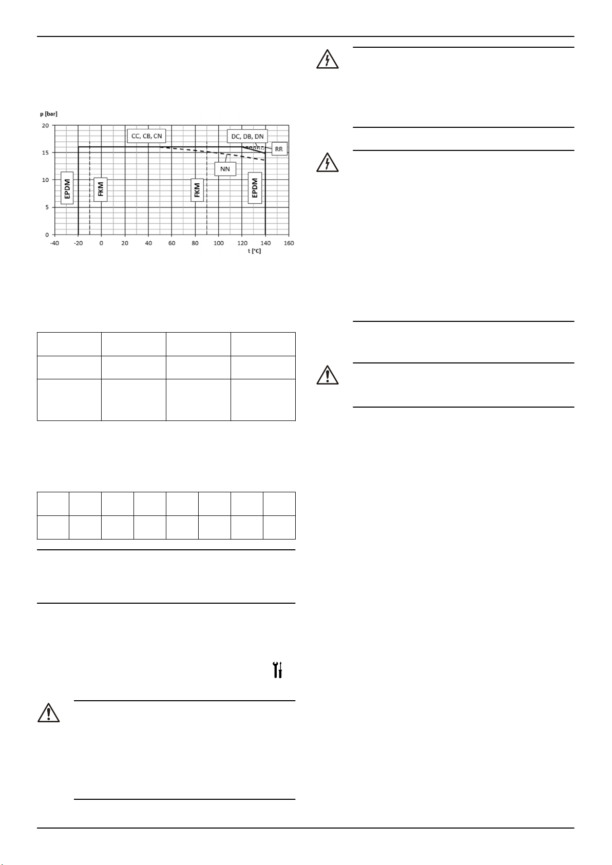
ru - Перевод с оригинала
3.7 Ограничения применения
Максимальное рабочее давление
В данной блок-схеме показано максимальное рабочее давление в
зависимости от модели насоса и температуры прокачиваемой
жидкости.
+ P
P
1max
P
1max
P
max
PN Максимальное рабочее давление
Диапазон температуры жидкости
Версия
Стандарт Этилен-пропи-
Опция FPM (FKM -
Относительно специальных требований обратитесь в отдел продаж и обслуживания.
Максимальное количество пусков в час
В данной таблице показано допустимое количество пусков в час
для двигателей, поставляемых компанией Lowara Lowara:
kW
Пусков
в час
ПРИМЕЧАНИЕ:
При использовании двигателя, который отличается от стандартного двигателя, входящего в комплект поставки электронасоса, обратитесь к соответствующим инструкциям, где приведено допустимое количество запусков в час.
Уровень шума
Уровни звукового давления на измерительной поверхности LpAприведены в Табл. 15
≤ PN
max
Максимальное входное давление
Максимальное давление, создаваемое насосом
Прокладка Минимальный Максималь-
лен (EPDM)
фторсодержащий эластомер)
0,25—
4,00—
3,00
7,50
60 40 25 16 8 4 3
-20°C (-4°F) 140°C (284°F)
-10°C (14°F) 90°C (194°F)
11—22 30—37 45—75 90—
ный
160
185—
355
4 Установка
Меры предосторожности
ПРЕДУПРЕЖДЕНИЕ:
• Соблюдайте действующие нормы по предотвращению несчастных случаев на производстве.
• Следует использовать подходящее оборудование и
защитные устройства.
• При выборе места установки, а также подключении
трубопроводов и электроэнергии следует руководствоваться действующими законодательными и нормативными актами национального и местного уровня.
Опасность поражения электрическим током:
• Все подключения должны выполняться квалифицированным монтажниками в соответствии с действующими нормами.
• Перед работой с блоком убедитесь в том, что блок и
панель управления обесточены и подача энергии
невозможна. Это также относится к цепи управления.
Заземление
Опасность поражения электрическим током:
• Прежде чем устанавливать электрические соединения, обязательно подключайте внешний защитный
проводник к зажиму заземления.
• Необходимо заземлить все электрооборудование.
Это требование относится к насосному оборудованию, приводам и аппаратуре контроля. Проверьте
правильность подключения провода заземления.
• Если кабель двигателя ошибочно выдернут, заземляющий провод должен отключаться от зажима в
последнюю очередь. Убедитесь в том, что длина заземляющего провода больше, чем длина фазных
проводов. Это относится к обоим концам кабеля
двигателя.
• Добавить дополнительную защиту от смертельного
поражения. Установить высокочувствительный дифференциальный выключатель (30 мА) [устройство
остаточного тока RCD].
4.1 Требования на объекте
4.1.1 Расположение насоса
ОПАСНОСТЬ:
Запрещено использовать насос в помещениях, где могут
содержаться огне- и взрывоопасные или агрессивные газо- или порошкообразные вещества.
Указания
Соблюдайте следующие указания относительно расположения изделия.
• Убедитесь в том, что никакие препятствия не мешают нормальному потоку охлаждающего воздуха, подаваемого вентилятором двигателя.
• Убедитесь, что площадь установки защищена от утечек жидкости или затопления.
• По возможности расположите насос немного выше уровня пола.
• Температура окружающей среды должна составлять от 0°C
(+32°F) до +40°C (+104°F).
• Относительная влажность окружающего воздуха должна быть
меньше 50% при +40°C (+104°F).
• Обращайтесь в отдел продаж и обслуживания в следующих
случаях.
• Относительная влажность воздуха не соответствует указаниям.
• Комнатная температура превышает +40°C (+104°F).
• Устройство расположено на высоте более 1000 м (3000
футов) над уровнем моря. Может понадобиться сокращение производительности двигателя или замена более
мощным двигателем.
Информацию о том, на сколько сокращать производительность
двигателя см. в Табл. 16 .
Положение насоса и свободные промежутки
Обеспечьте соответствующее освещение и свободные промежутки
вокруг насоса. Убедитесь в том, что существует простой доступ к
насосу для установки и техобслуживания.
Установка над поверхностью жидкости (высота всасывания)
Теоретическая максимальная высота любого насоса составляет
10,33 мм На практике, на мощность всасывания насоса влияет
следующее:
• Температура жидкости
• Подъем над уровнем моря (в открытой системе)
• Давление в системе (в закрытой системе)
• Сопротивление труб
• Собственное сопротивление насоса потоку
• Разница высот
e-NSC Installation, Operation, and Maintenance Manual 53
Page 54

ru - Перевод с оригинала
Следующая формула используется для расчета максимальной высоты над уровнем жидкости, на которой можно установить насос:
(pb*10,2 - Z) ≥ NPSH + Hf + Hv + 0,5
p
Барометрическое давление в барах, в закрытой системе
b
оно отображает давление системы
NPSH Значение собственного сопротивления насоса потоку в
метрах
H
Общие потери в метрах, вызванные проходом жидкости че-
f
рез всасывающую трубу насоса
H
Давление пара в метрах, соответствующее температуре
v
жидкости Т °C
0,5 Рекомендуемый предел безопасности (м)
Z Максимальная высота, на которой можно установить насос
(м)
Дополнительную информацию см. в разделе Рис. 17 .
(pb*10,2 - Z) должно быть всегда положительное число.
ПРИМЕЧАНИЕ:
Не допускайте превышения допустимой всасывающей способности насоса; это может привести к кавитации и повреждению насоса.
4.1.2 Требования к трубопроводу
Меры предосторожности
ПРЕДУПРЕЖДЕНИЕ:
• Следует использовать трубы, соответствующие максимальному рабочему давлению насоса. Невыполнение данных указаний может привести к разрушению системы, с риском получения травм.
• Все подключения должны выполняться квалифицированным монтажниками в соответствии с действующими нормами.
ПРИМЕЧАНИЕ:
При подключении насоса к централизованной системе водоснабжения необходимо следовать действующим законодательным нормам и правилам компаний, которые управляют водными ресурсами. При необходимости, установите со стороны всасывания подходящее устройство предотвращения обратного течения.
Контрольный список проверки трубопровода
Соблюдайте следующие правила:
• у всего трубопровода имеется независимая опора, трубопровод не создает нагрузку на насос;
• Гибкие трубы или соединения используются, чтобы избежать
передачи вибрации насоса трубам или наоборот.
• использовать широкие колена, избегать использования изгибов, создающих избыточное сопротивление потока;
• всасывающий трубопровод полностью герметичен и воздухонепроницаем;
• если насос используется в открытом контуре, убедитесь в
том, что диаметр всасывающей трубы соответствует условиям установки. Всасывающая труба не должна быть меньше, чем диаметр всасывающего отверстия.
• если всасывающий трубопровод должен быть больше, чем
всасывающая сторона насоса, устанавливается эксцентрическая переходная муфта трубы.
• Если насос располагается над уровнем жидкости, ножной
клапан устанавливается в конце всасывающей трубы.
• Ножной клапан полностью погружается в жидкость таким образом, чтобы воздух не мог попасть через всасывающую воронку, когда жидкость находится на минимальном уровне и
насос установлен над уровнем источника жидкости.
• Двухпозиционные клапаны соответствующего размера установлены на всасывающем трубопроводе и на подающем трубопроводе (ниже по потоку за обратным клапаном) для регулирования продуктивности насоса, для осмотра насоса и для
технического обслуживания.
• Двухпозиционный клапан соответствующего размера установлен на подающем трубопроводе (ниже по потоку за обратным клапаном) для регулирования продуктивности насоса,
для осмотра насоса и для технического обслуживания.
• Чтобы избежать обратного потока в насос, когда насос выключен, устанавливается обратный клапан на подающий трубопровод.
ПРЕДУПРЕЖДЕНИЕ:
Не использовать закрытый двухпозиционный клапан на
выпускной стороне, чтобы прерывать поток насоса более
чем на несколько секунд. Если насос должен работать с
закрытой выпускной стороной дольше нескольких секунд, необходимо установить обводный контур во избежание перегревания жидкости внутри насоса.
Иллюстрации, на которых приведены требования к трубопроводу,
см. на Рис. 18 и Рис. 19 .
4.2 Требования к электрооборудованию
• Действующие местные нормативы преобладают над данными
требованиями.
• Для систем пожаротушения (гидранты и/или спринклеры)
проверить действующие местные нормы.
Список проверок электрических соединений
Соблюдайте следующие правила:
• Электрические проводники должны быть защищены от высоких температур, вибрации и ударов.
• Линия питания должна быть оснащена:
• устройством защиты от короткого замыкания;
• Сетевым изолирующим выключателем с контактным зазором не менее 3 мм.
Контрольный список для проверки электрической панели
управления
ПРИМЕЧАНИЕ:
Панель управления должна соответствовать техническим характеристикам электрического насоса. (неправильные сочетания не гарантируют защиту двигателя);
Соблюдайте следующие правила:
• Панель управления должна защищать двигатель от перегрузки и коротких замыканий;
• установите правильную защиту от перегрузки (термическое
реле или предохранитель двигателя).
Тип насоса
Однофазный стандартный
электрический насос ≤ 1,5 кВт
Трехфазный электрический
насос и другие однофазные
12
насосы
• Панель управления должна быть оборудована системой защиты от работы всухую, к которой подключаются реле давления, плавающий переключатель, щупы или прочие подходящие устройства.
• Рекомендуется использовать следующие устройства на стороне всасывания насоса:
• При перекачивании жидкости из водяной системы используйте реле давления.
• При перекачивании жидкости из накопительного бака
или резервуара используйте поплавковый переключатель или датчики.
• при использовании термореле рекомендуется использовать
реле, чувствительные к пропаданию фазы.
Защита
• Встроенный автоматический сброс термо-амперометрического предохранителя (защита двигателя)
• Защита от короткого замыкания (обеспечивается монтажником)
• Термическая защита
(обеспечивается монтажником)
• Защита от короткого замыкания (обеспечивается монтажником)
11
11
плавкие предохранители aM (запуск двигателя), или магнето-термовыключатель с кривой C и Icn ≥ 4,5 кA или другими аналогичными устройствами.
12
Термическое реле перегрузки с классом работы 10А + плавкие предохранители аМ (запуск двигателя) или магнето-термический переключатель защиты
двигателя с классом работы 10А.
54 e-NSC Installation, Operation, and Maintenance Manual
Page 55

ru - Перевод с оригинала
Контрольный список для проверки двигателя
ПРЕДУПРЕЖДЕНИЕ:
• Прочитайте инструкцию по эксплуатации, чтобы
убедиться в наличии предохранительного устройства, если используется двигатель, отличный от
стандартного.
• Если двигатель оснащен автоматическими устройствами тепловой защиты, необходимо учитывать
риск непредвиденного запуска при перегрузке. Двигатели такого типа запрещено использовать в противопожарных и спринклерных системах.
ПРИМЕЧАНИЕ:
• Используйте только динамически сбалансированные двигатели со шпонкой половинной высоты (полушпонкой) на конце
вала (IEC 60034-14) и нормальным значением вибрации (N).
• Напряжение сети и частота должны соответствовать спецификациям, указанным на табличке технических данных.
• Допускается использование только одно- и трехфазных двигателей, которые соответствуют европейским стандартам с точки зрения размеров и мощности.
В общем, двигатель может работать со следующими допусками
напряжения в сети:
Частота, Гц Фаза ~ Un, В ± %
50 1 220 – 240 ± 6
3 230/400 ± 10
400/690 ± 10
60 1 220 – 230 ± 6
3 220/380 ± 5
380/660 ± 10
Использование кабеля в соответствии с правилами с 3 контактами
(2+заземление) для версий с одной фазой и с 4 контактами (3+ заземление) для трехфазной версии.
4.3 Установка насоса
4.3.1 Механическая установка
Перед установкой проверить следующее:
• Использовать бетон, который соответствует классу прочности
на сжатие C12/15 и требованиям классу воздействия XC1 по
EN 206-1.
• Установочная поверхность должна быть ровной и точно горизонтальной.
• Обратите внимание на вес.
Монтаж агрегата на фундамент
Информацию об основании насоса и анкерных отверстиях см. в
Рис. 20 .
Фундамент должен иметь размеры, указанные на контурном/
компоновочном чертеже.
1. Расположите насос на фундаменте и выровняйте с помощью
спиртового уровня, поместив его на вал и выходной патрубок.
Допускается отклонение не более 0,2 мм/м.
2. Снимите пробки с портов.
3. Выровняйте насос и фланцы трубопровода с обеих сторон
насоса. Проверьте выравнивание болтов.
4. Прикрепите трубопровод болтами к насосу. Не устанавливайте трубопровод с усилием.
5. Для компенсации по высоте используйте регулировочные
прокладки (2).
Регулирование прокладки применяйте одновременно к левым
и правым болтам (3) между опорной рамой и фундаментом.
Для регулировки расстояния между болтами (L) > 800 мм установите дополнительные регулировочные прокладки (2) посредине между отверстиями под болты.
6. Все регулировочные прокладки должны лежать ровно.
7. Вставьте болты крепления к фундаменту (3) в предусмотренные отверстия.
8. Для заделки болтов крепления к фундаменту (3) используйте
бетон.
9. После застывания бетона отрегулируйте опорную плиту.
10. Плотно и равномерно затяните болты крепления к фундаменту (3).
Примечание:
• Для опорной плиты рекомендуется (жидкий) цементный раствор.
• Чтобы погасить вибрацию, между насосом и фундаментом
используйте опоры, абсорбирующие вибрацию.
Крепление насоса на основании
Проверьте, чтобы:
• опорное основание не изгибалось и не вибрировало (в резонанс) во время работы;
• монтажные поверхности опоры насоса и двигателя к опорной
раме должны быть плоскими (рекомендуется машинная обработка);
• нужно гарантировать безопасное крепление насоса и двигателя;
• в зависимости от используемой муфты нужно обеспечить достаточное расстояние между насосом и двигателем;
• Между насосом и опорным основанием должны быть установлены соответствующие регулировочные прокладки, чтобы
иметь возможность регулировки по высоте (рекомендуется
запас регулировки 4-6 мм).
4.3.2 Контрольный список проверки трубопровода
Проверьте, чтобы:
• Трубопровод на всасывании должен быть установлен с постоянным подъемом, с кавитационным запасом с наклоном в
сторону насоса.
• Номинальный диаметр трубопровода должен соответствовать
номинальному диаметру штуцеров насоса.
• Трубопровод должен быть закреплен в непосредственной
близости от насоса и подсоединен к насосу без какого-либо
натяжения.
ОСТОРОЖНО:
Окалина, брызги металла и другие включения приведут к
повреждению насоса.
• В трубопроводе не должно быть посторонних материалов.
• При необходимости нужно установить фильтр.
• Соблюдайте "Допустимые усилия и моменты на фланцах",
см. Рис. 21
Данные усилий и моментов применимы только для статического
случая. Значения применимы, только если насос установлен на
опорную плиту и жестко прикреплен к ровному фундаменту.
4.3.3 Установка соосности муфты
После крепления к фундаменту и подключения трубопровода нужно снова выставить соосность муфты, даже если агрегат при поставке был установлен на единую раму.
Рис. 16: Установка соосности стандартной муфты
Рис. 17: Установка соосности распорной муфты
e-NSC Installation, Operation, and Maintenance Manual 55
Page 56

ru - Перевод с оригинала
1. Верхняя половина кожуха муфты
2. Нижняя половина кожуха муфты
3. Регулируемая деталь
Снимите защитный кожух муфты.
1. Ослабьте крепление опоры и затяните снова, не оставляя никаких остаточных напряжений.
2. Положите линейку (1) вдоль на обе полумуфты.
3. С линейкой (1) в этом положении поверните муфту от руки.
• Соосность муфты выставлена правильно, если расстояние a и b до валов одинаковое во всех точках по окружности.
• Радиальное и аксиальное отклонение между полумуфтами не должно превышать значений в таблице xyz в холодном состоянии, а также в условиях с рабочей температурой и под входным давлением.
4. Проверьте расстояние (размеры указаны на сборочном чертеже) между двумя полумуфтами по окружности с помощью щупа (4). Соосность муфты выставлена правильно, если расстояние между полумуфтами одинаковое во всех точках по
окружности.
• Радиальное и аксиальное отклонение между полумуфтами не должно превышать значений в таблице xyz в холодном состоянии, а также в условиях с рабочей температурой и под входным давлением.
ПРИМЕЧАНИЕ:
После установки соосности и перед запуском установите кожух.
Примечание: еще раз проверьте соосность муфты в рабочем прогретом состоянии и под давлением в системе (если имеется) и при
необходимости отрегулируйте повторно. Заблаговременно прочтите информацию в главе 6! Вал должен легко и плавно проворачиваться от руки.
ПРИМЕЧАНИЕ:
Неправильная установка соосности может привести к повреждению муфты и агрегата.
4.3.4 Установка защитного кожуха муфты
ОСТОРОЖНО:
Эксплуатация насоса без надлежащим образом установленного защитного кожуха муфты запрещена.
Рис. 18: Половины кожуха муфты
2. Соедините и закрепите силовые кабели в соответствии с
электрической схемой.
Электрические схемы см. в Рис. 24 . Схемы также доступны
сзади крышки клеммной коробки.
a) Подключите провод заземления.
Убедитесь в том, что длина заземляющего (корпусного)
провода больше, чем длина фазных проводов.
b) Присоедините провода фазы.
3. Установите на место крышку соединительной коробки.
ПРИМЕЧАНИЕ:
Аккуратно затяните сальники кабелей, чтобы гарантировать
защиту от проскальзывания кабеля и попадания влаги в соединительную коробку.
4. Если двигатель не оборудован автоматическим сбросом термозащиты, тогда отрегулируйте защиту от перегрузки в соответствии со списком ниже.
• Если двигатель используется с полной нагрузкой, установите значение на номинальное значение тока электрического двигателя (табличка технических данных)
• Если двигатель используется с частичной нагрузкой, установите значение на рабочий ток (например, измеряемое специальным пинцетом).
• Если у насоса пусковая система звезда-треугольник, отрегулируйте термореле на 58% номинального или рабочего тока (только для трехфазных двигателей).
5 Ввод в эксплуатацию, запуск, эксплуатация и останов
Меры предосторожности
ПРЕДУПРЕЖДЕНИЕ:
• Убедитесь в том, что сливаемая жидкость не может
вызвать повреждений и травм.
• Защитные устройства двигателя могут стать причиной непредвиденного запуска двигателя. Это может
привести к тяжелым травмам.
• Эксплуатация насоса без надлежащим образом установленного защитного кожуха муфты запрещена.
ОСТОРОЖНО:
• Внешние поверхности насоса и двигателя могут нагреваться выше 40ºC (104ºF) во время эксплуатации. Не прикасайтесь ни какими частями тела без
защитного снаряжения.
• Не помещайте рядом с насосом горючие материалы.
ПРИМЕЧАНИЕ:
• Эксплуатация насоса при недостижении минимального номинального расхода, на сухом ходу или без заливки строго запрещена.
• Никогда не эксплуатируйте насос с закрытым клапаном подачи дольше нескольких секунд.
• Эксплуатация насоса при перекрытом впускном клапане строго запрещена.
• Не подвергайте неработающий насос воздействию низких
температур. Сливайте всю жидкость, находящуюся в насосе.
В противном случае жидкость может замерзнуть и повредить
1. Нижняя половина кожуха муфты
2. Верхняя половина кожуха муфты
3. Регулировка половины
1. Привинтите нижнюю половину (1) винтами (S1) к нижней стороне кольца крышки подшипника (4).
2. Вставьте регулируемую деталь (3) прорезью вниз и подвиньте
аксиально внутрь двигателя.
3. Привинтите верхнюю половину (1) винтами (S2) к верхней
стороне кольца крышки подшипника (4).
4. Соедините части 1 и 2 вместе, зафиксировав регулируемую
деталь.
4.3.5 Электрооборудование
1. Снимите винты крышки клеммной коробки.
насос.
• Сумма давления на стороне всасывания (водопроводная магистраль, напорный резервуар) и максимальное давление,
обеспечиваемое насосом, не должны превышать максимальное допустимое для насоса рабочее давление (номинальное
давление PN).
• Прекратите эксплуатацию насоса в случае возникновения кавитации. Кавитация может привести к повреждению внутренних элементов.
Уровень шума
Значения уровней шума отдельно для насоса и насоса со стандартным двигателем приведены в таблице 10.
5.1 Заполнение насоса
Информация по дополнительным соединениям насоса приведена
на Рис. 25 .
56 e-NSC Installation, Operation, and Maintenance Manual
Page 57

ru - Перевод с оригинала
Установки с уровнем жидкости над насосом (напор)
Иллюстрации деталей насоса см. Рис. 26 .
1. Закройте двухпозиционный клапан после насоса.
2. Снимите пробку заливки (3) или контрольную пробку (1) и откройте двухпозиционный клапан выше по линии, пока вода не
начнет поступать из отверстия.
a) Закройте пробку заливки (3) или контрольную пробку (1).
Установка с уровнем жидкости ниже насоса (высота
всасывания)
Иллюстрации деталей насоса см. Рис. 27 .
1. Система трубопроводов не заполнена:
a) Откройте двухпозиционный клапан, расположенный пе-
ред насосом, и закройте
b) Снимите пробку заливки (3) и контрольную пробку (1), с
помощью лейки залейте через отверстие заливки (3),
чтобы вода начала поступать из отверстия.
c) Затяните пробку заливки (3) и контрольную пробку (1).
2. Заполненная система трубопроводов на нагнетании:
a) Откройте двухпозиционный клапан, расположенный пе-
ред насосом, и закройте двухпозиционный клапан после
насоса.
b) Снимите контрольную пробку (1), чтобы вода начала по-
ступать из отверстия.
c) Затяните контрольную пробку (1).
5.2 Проверить направление вращения
(трехфазный двигатель)
Следуйте данной процедуре перед запуском.
1. Найдите стрелки на адаптере или крышке вентилятора двигателя, чтобы определить правильное направление вращения.
2. Включите двигатель.
3. Быстро проверьте направление вращения через кожух муфты
или крышку вентилятора двигателя.
4. Отключите двигатель.
5. Если направление вращения неправильное, выполните следующие действия:
a) Обесточьте устройство.
b) В клеммной коробке двигателя или в электрической па-
нели управления поменяйте положение двух или трех
проводов силового кабеля.
Электрические схемы см. в Рис. 24 .
c) Снова проверьте направление вращения.
5.3 Пуск насоса
Монтажник или владелец ответственны за проверку правильности
расхода и температуры перекачиваемой жидкости.
Перед запуском насоса убедитесь в том, что:
• насос правильно подключен к электропитанию,
• насос правильно наполнен в соответствии с инструкциями в
разделе Заполнение насоса (глава 5).
• двухпозиционный клапан, расположенный после насоса, закрыт.
1. Включите двигатель.
2. Плавно откройте двухпозиционный клапан на стороне выпуска насоса.
При ожидаемых рабочих условиях насос должен работать
ровно и тихо. В противном случае см. Устранение.
6 Техническое обслуживание
Меры предосторожности
Опасность поражения электрическим током:
Перед установкой или техническим обслуживанием насоса следует отключить и заблокировать подачу электропитания.
ПРЕДУПРЕЖДЕНИЕ:
• К техническому обслуживанию и сервисному обслуживанию следует допускать только квалифицированный опытный персонал.
• Соблюдайте действующие нормы по предотвращению несчастных случаев на производстве.
• Следует использовать подходящее оборудование и
защитные устройства.
• Убедитесь в том, что сливаемая жидкость не может
вызвать повреждений и травм.
6.1 Техническое обслуживание
Если пользователь желает запланировать сроки регулярного техобслуживания, они зависят от типа нагнетаемой жидкости и от условий эксплуатации насоса.
Относительно информации о регулярном техобслуживании или
ремонте обращайтесь в отдел продаж и обслуживания.
Дополнительное техобслуживание может понадобиться для очистки проточной части и/или замены изношенных деталей.
Типы подшипников
• Смазочные вещества и замена смазки роликовых подшипников
• Подшипники с консистентной смазкой
• Подшипники с консистентной смазкой смазываются на
заводе. Размеры подшипников и тип смазочного материала указаны в таблице 6.
Насосы с однократно смазанными подшипниками
Насосы с однократно смазанными подшипниками не подлежат периодическому обслуживанию.
Насосы со смазываемыми подшипниками
• Повторное смазывание выполнять через 4000 часов работы,
но не реже, чем раз в год. Сначала очистите смазочные ниппели (SN).
• Используйте смазочный материал NLGI сорта 2 или аналогичный.
• Соответствующее количество смазочного вещества приведено в таблице 6.
6.2 Значения крутящего момента затяжки
Информация о значениях крутящих моментов и данные насоса
приведены в Рис. 28 , данные по опорной плите - в Табл. 29 .
6.3 Контрольный список проверки
Проверка муфты
Проверка механического уплотнения
Проверка уплотнений подшипника
Проверить эластичные элементы муфты. Заменить изношенные детали и проверить соосность муфты.
Проверить механическое уплотнение на утечку. Заменить механическое уплотнение в случае
утечки.
Проверить правильное расположение уплотнительных колец на
валу. Кромка уплотнения должна только касаться уплотнительной поверхности.
6.4 Разборка и замена частей насоса
Более подробная информация по запасным частям, разборке и
сборке насоса приведена на рис Рис. 1 , Рис. 2 , Рис. 3 или Рис. 4 .
На нашей странице в Интернете можно загрузить инструкцию по
ремонту и сборке.
7 Устранение
7.1 Поиск и устранение неисправностей для пользователей
Главный выключатель включен, но электрический насос не запускается.
e-NSC Installation, Operation, and Maintenance Manual 57
Page 58

ru - Перевод с оригинала
Причина Устранение
Сработала термозащита
встроенная в насос (если
есть).
Сработало предохранительное устройство от сухого хода.
Электрический насос запускается, но с различным интервалом после этого срабатывает термическая защита.
Причина Устранение
Присутствуют инородные тела
(твердые или волокнистые материалы) внутри насоса, которые засорили крыльчатку.
Насос перегружен, поскольку
он качает более плотную или
вязкую жидкость.
Насос работает, но подает слишком мало или вообще не жидкость.
Причина Устранение
Насос засорен. Обратитесь в отдел продаж и обслуживания.
Поиск и устранение неисправностей в таблицах ниже только для
монтажников.
Подождите, пока насос остынет.
Термозащита будет сброшена автоматически.
Проверить уровень воды в баке
или давление магистрали.
Обратитесь в отдел продаж и обслуживания.
Проверить фактические требования на основе характеристик качаемой насосом жидкости, а затем обратиться в отдел продаж и
обслуживания.
7.2 Главный переключатель включен, но электрический насос не запускается
Причина
Отсутствует подача питания. • Восстановите подачу питания.
Сработала термозащита
встроенная в насос (если
есть).
Сработало термореле или
предохранитель двигателя в
электрической панели управления.
Сработало предохранительное устройство от сухого хода.
Перегорели предохранители
или вспомогательные контуры насоса.
Устранение
• Убедитесь в том, что все электрические соединения к источнику питания исправны.
Подождите, пока насос остынет.
Термозащита будет сброшена автоматически.
Выполните сброс устройства тепловой защиты
Проверьте:
• уровень жидкости в баке, или
давление магистрали;
• предохранительные устройства и соединительные кабели.
Замените предохранители.
7.3 Электрический насос запускается, но сразу же срабатывает термопредохранитель или перегорают плавкие предохранители.
Причина
Поврежден силовой кабель
питания.
Термическая защита или
плавкие предохранители не
подходят для тока двигателя.
Короткое замыкание электродвигателя.
Перегрузка двигателя. Проверьте условия эксплуатации
Устранение
Проверьте кабель и замените при
необходимости.
Проверьте компоненты и замените
при необходимости.
Проверьте компоненты и замените
при необходимости.
насоса и выполните сброс защиты.
7.4 Электрический насос запускается, но вскорости после этого срабатывает термический предохранитель или перегорают плавкие предохранители.
Причина Устранение
Электрический пульт расположен в сильно нагреваемом
участке или на него попадают
прямые солнечные лучи.
Напряжение электропитания
выходит за рабочие пределы
двигателя.
Отсутствует фаза питания. Проверьте
Защитите электрический пульт от
источника нагревания и прямых
солнечных лучей.
Проверьте условия эксплуатации
двигателя.
• электропитание
• электрическое соединение
7.5 Электрический насос запускается, но срабатывает термический предохранитель через различное время после этого
Причина Устранение
Присутствуют инородные
тела (твердые или волокнистые материалы)
внутри насоса, которые
засорили крыльчатку.
Скорость подачи насоса
больше, чем пределы,
указанные на табличке
технических данных.
Насос перегружен, поскольку он качает более
плотную или вязкую жидкость.
Подшипники двигателя изношены.
Обратитесь к местному представителю компании по продажам и обслуживанию.
Частично закройте двухпозиционный
клапан ниже на линии, пока скорость
подачи не будет равна или меньше,
чем пределы, указанные на табличке
технических данных.
Проверьте фактические требования к
мощности на основании свойств нагнетаемой жидкости и замените насос
соответственно.
Обратитесь к местному представителю компании по продажам и обслуживанию.
7.6 Электрический насос запускается, но активирована общая защита системы.
Причина
Короткое замыкание электрической системы.
Устранение
Проверьте электрическую систему.
7.7 Электрический насос запускается, но активировано устройство остаточного тока системы (RCD).
Причина
По проводнику заземления
течет ток.
Устранение
Проверьте изоляцию компонентов
электрической системы.
7.8 Насос работает, но подает слишком мало или вообще не жидкость.
Причина
Присутствует воздух
внутри насоса или трубопровода.
Устранение
• Обезвоздушьте.
58 e-NSC Installation, Operation, and Maintenance Manual
Page 59

ru - Перевод с оригинала
Причина Устранение
Насос неправильно заполнен.
Повышенное дросселирование на стороне подачи.
Клапаны заблокированы
в закрытом или частично
закрытом положении.
Насос засорен. Обратитесь к местному представителю
Трубопровод засорен. Проверить и почистить трубы.
Неправильное направле-
ние вращения крыльчатки.
(трехфазная версия)
.
Высота всасывания слишком большая или слишком большое сопротивление потока во всасывающих трубах.
Остановите насос и повторите процедуру заполнения.
Если проблема не устранена:
• проверьте отсутствие течи механических уплотнений;
• проверьте герметичность всасывающей трубы.
• Замените клапаны с утечкой.
Откройте клапан.
Разобрать и почистить клапаны.
компании по продажам и обслуживанию.
Изменить положение двух фаз на панели выводов двигателя или в электрической панели управления.
Проверьте условия эксплуатации насоса. При необходимости выполнить следующее:
• сократить высоту всасывания;
• увеличить диаметр всасывающей
трубы.
Причина Устранение
Внутри насоса
находятся посторонние объекты.
В другом случае обратитесь в отдел продаж и обслуживания.
Обратитесь к местному представителю компании по продажам и обслуживанию.
7.9 Электрический насос останавливается, а затем вращается в неправильном направлении.
Причина
Присутствует утечка в одном или обоих
компонентах:
• всасывающая труба;
• ножной клапан или обратный клапан.
Присутствует воздух во всасывающей
трубе.
Устранение
Отремонтировать или
заменить неисправный
компонент.
Обезвоздушьте.
7.10 Насос запускается слишком часто
Причина
Присутствует утечка в одном или обоих компонентах:
• всасывающая труба;
• ножной клапан или обратный
клапан.
Разорвана мембрана или отсутствует
предварительный заряд воздуха в напорном баке.
Устранение
Отремонтировать или заменить неисправный компонент.
См. соответствующие инструкции в руководстве к
напорному баку.
7.11 Насос вибрирует и создает сильный шум
Причина
Кавитация насо-саСократите необходимую скорость потока, ча-
Подшипники двигателя изношены.
Устранение
стично закрыв двухпозиционный клапан после
насоса. Если проблема не устранена, проверьте условия эксплуатации насоса (например,
разность высот, сопротивление потока, температура жидкости и т. д.)
Обратитесь к местному представителю компании по продажам и обслуживанию.
e-NSC Installation, Operation, and Maintenance Manual 59
Page 60

100-160 125-200 150-200 200-250
100-200 125-250 150-250 200-315
100-250 125-315 150-315 250-315
it • en • fr • de • tr • ru
Appendice tecnica • Technical appendix • Technischer Anhang • Teknik ek • Техническое приложение
1.
60 e-NSC Installation, Operation, and Maintenance Manual
Page 61

100-315
100-400
125-400
150-400
it • en • fr • de • tr • ru
2.
e-NSC Installation, Operation, and Maintenance Manual 61
Page 62

200-400
250-400
300-350
300-400
it • en • fr • de • tr • ru
3.
62 e-NSC Installation, Operation, and Maintenance Manual
Page 63

150-500
200-500
250-500
300-450
it • en • fr • de • tr • ru
4.
102 Corpo a spirale • Volute casing • Spiralgehäuse • Kıvrım kutusu • Спиралевидный кожух
161 Copertura corpo pompa • Casing cover • Gehäusedeckel • Kutu kapağı • Крышка кожуха
183 Piede di supporto • Support foot • Stützfuß • Ayak desteği • Основание опоры
210 Albero • Shaft • Welle • Şaft • Вал
230 Girante • Impeller • Laufrad • Çark • Рабочее колесо
e-NSC Installation, Operation, and Maintenance Manual 63
Page 64

NSC F H 125-315 / 220 A / W 4 5V C C 4 xx
765a
5
1 2 3 4
13
121110
8 9
1310
it • en • fr • de • tr • ru
321 Cuscinetto a sfera radiale • Radial ball bearing • Radialkugellager • Radyal bilyalı rulman • Радиальный шарикоподшипник
330 Staffa del cuscinetto • Bearing bracket • Lagerträger • Rulman mesnedi • Кронштейн подшипника
360 Coperchio del cuscinetto • Bearing cover • Lagerdeckel • Rulman kapağı • Крышка подшипника
411 Guarnizione • Gasket • Flachdichtung • Conta • Прокладка
412 Guarnizione O-ring • O-ring • O-Ring • O-ring • Уплотнительное кольцо
433 Tenuta meccanica • Mechanical seal • Gleitringdichtung • Mekanik keçe • Механическое уплотнение
502 Anello usura • Wear ring • Spaltring • Aşınma halkası • Компенсационное кольцо
504 Anello distanziatore • Spacer ring • Abstandring • Ara halkası • Распорное кольцо
507 V-ring • V-ring • V-Ring • V-halka • Шевронная манжета
554 Rondella • Washer • Unterlegscheibe • Rondela • Шайба
681 Protezione di sicurezza • Safety guard • Schutzgitter • Güvenlik koruması • Защитное ограждение
901 Vite a testa esagonale • Hexagonal head screw • Sechskantschraube • Altıgen başlı vida • Винт с шестигранной головкой
902 Bullone perno • Stud bolt • Stiftschraube • Yuvarlak vida • Резьбовая шпилька
903 Tappo • Plug • Verschlussschraube • Tapa • Пробка
904 Vite di bloccaggio • Grub screw • Gewindestift • Ayar vidası • Винт с плоским концом и шлицем под отвертку
922 Dado della girante • Impeller nut • Laufradmutter • Çark somunu • Гайка крыльчатки
923 Dado del cuscinetto • Bearing nut • Lagermutter • Rulman somunu • Гайка подшипника
931 Piastra di bloccaggio • Lock plate • Sicherungsblech • Kilitleme plakası • Стопорная пластина
940 Chiave • Key • Passfeder • Anahtar • Шпонка
Appendice tecnica • Technical appendix • Technischer Anhang • Teknik ek • Техническое приложение
5. 6.
7. 8.
9.
64 e-NSC Installation, Operation, and Maintenance Manual
Page 65

it • en • fr • de • tr • ru
Italiano
1. NSC = Tipo pompa
2. Indicazione giunto; asse nudo, F = montato su telaio, C = telaio montato con
giunto distanziale, A = staffa cuscinetto
avanzata
3. Controller/altro tipo di trasmissione; motore elettrico standard, H = dotato di Hydrovar, X = altra opzione di trasmissione
4. 125–315 = Dimensione della pompa
5. 220 = Potenza nominale (kWx10)
a. I310 = Diametro girante, utilizzata
solo con pompa ad asse nudo
6. A = Informazioni assetto girante
7. Tipo di motore, P = Motore PLM, W =
Motore WEG, X = Motore di altra marca
8. Numero di poli; 2 = Motore a 2 poli, 4 =
Motore a 4 poli, 6 = Motore a 6 poli
9. Tensione e frequenza elettrica;
5H 1x220-240 V; 50 Hz
5R 3x220-240/380-415 V; 50 Hz
5V 3x380-415/660-690 V; 50 Hz
5P 3x200-208/346-360 V; 50 Hz
5S 3x255-265/440-460 V; 50 Hz
5T 3x290-300/500-525 V; 50 Hz
5W 3x440-460/-; 50 Hz
6F 1x220-230 V; 60 Hz
6E 1x200-210 V; 60 Hz
6P 3x2220-230/380-400
6R 3x255-277/440-480 V; 60 Hz
6V 3x440-480/-; 60 Hz
6U 3x380-400/660-690 V; 60 Hz
6N 3x200-208/346-360 V; 60 Hz
6T 3x330-346/575-600 V; 60 Hz
10. Materiale corpo pompa
11. Materiale della girante
12. Tenuta meccanica + configurazione materiale O-ring/vedere tabella 3
13. Cifre libere per le opzioni
English
1. NSC = Pump type
2. Coupling indication; bare shaft, F = frame- mounted, C = frame mounted with
spacer coupling, A = advanced bearing
bracket
3. Controller / other drive type; standard
electric motor, H = equipped with Hydrovar, X = other drive option
4. 125–315 = Pump size
5. 220 = Rated motor power (kWx10)
a. I310 = Impeller diameter, only used
with bare shaft pump
6. A = Impeller trim information
7. Motor type, P = PLM motor, W = WEG
motor, X = Other motor brand
8. Number of poles; 2 = 2–pole motor, 4 =
4–pole motor, 6 = 6–pole motor
9. Electrical voltage and frequency;
5H 1x220-240V; 50 Hz
5R 3x220-240/380-415V; 50 Hz
5V 3x380-415/660-690V; 50 Hz
5P 3x200-208/346-360V; 50 Hz
5S 3x255-265/440-460V; 50 Hz
5T 3x290-300/500-525V; 50 Hz
5W 3x440-460/-; 50 Hz
6F 1x220-230V; 60 Hz
6E 1x200-210V; 60 Hz
6P 3x2220-230/380-400
6R 3x255-277/440-480V; 60 Hz
6V 3x440-480/-; 60 Hz
6U 3x380-400/660-690V; 60 Hz
6N 3x200-208/346-360V; 60 Hz
6T 3x330-346/575-600V; 60 Hz
10. Casing material
11. Impeller material
12. Mechanical seal + O-ring material configuration / see table 3
13. Free digits for options
Deutsch
1. NSC = Pumpentyp
2. Kupplungsangabe; freiliegende Welle, F
= rahmenmontiert, C = rahmenmontiert
mit Abstandskupplung, A = besonderer
Lagerträger
3. Regler/anderer Antriebstyp; StandardElektromotor H = mit Hydrovar ausgestattet, X = andere Antriebsoption
4. 125–315 = Pumpengröße
5. 220 = Motornennleistung (kW x 10)
a. I310 = Laufraddurchmesser, nur
verwendet mit Pumpe mit freiliegender Welle
6. A = Informationen zum Einstellen des
Laufrads
7. Motortyp, P = PLM-Motor, W = WEGMotor, X = Andere Motorenmarke
8. Anzahl der Pole; 2 = 2–poliger Motor, 4
= 4–poliger Motor, 6 = 6–poliger Motor
9. Elektrische Spannung und Frequenz;
5H 1 x 220-240 V; 50 Hz
5R 3 x 220-240/380-415 V; 50 Hz
5V 3 x 380-415/660-690 V; 50 Hz
5P 3 x 200-208/346-360 V; 50 Hz
5S 3 x 255-265/440-460 V; 50 Hz
5T 3 x 290-300/500-525 V; 50 Hz
5W 3 x 440-460/-; 50 Hz
6F 1 x 220-230 V; 60 Hz
6E 1 x 200-210 V; 60 Hz
6P 3 x 2220-230/380-400
6R 3 x 255-277/440-480 V; 60 Hz
6V 3 x 440-480/-; 60 Hz
6U 3 x 380-400/660-690 V; 60 Hz
6N 3 x 200-208/346-360 V; 60 Hz
6T 3 x 330-346/575-600 V; 60 Hz
10. Gehäusewerkstoff
11. Laufradwerkstoff
12. Werkstoffkonfiguration für Gleitringdichtung + O-Ring/siehe Tabelle 3
13. Freie Ziffern für Optionen
Türkçe
1. NSC = Pompa tipi
2. Kaplin göstergesi, çıplak mil, F = takılı
iskelet, parça kaplinli takılan çerçeve, A
= gelişmiş rulman mesnedi
3. denetmen / diğer sürücü tipi; standart
elektrik motoru, H = Hydrovar donanımlı,
X = diğer sürücü seçeneği
4. 125–315 = Pompa boyutu
5. 220 = Anma motor gücü (kWx10)
a. I310 = Çark çapı, sadece çıplak mil
pompasıyla kullanılır
6. A = Çark trim bilgisi
7. Motor tipi, P = PLM motoru, W = WEG
motoru, X = Diğer motor markası
8. Kutup sayısı ; 2 = 2–kutup motoru, 4 =
4–kutup motoru, 6 = 6–kutup motoru
9. Elektrik voltajı ve frekansı
5H 1x220-240V; 50 Hz
5R 3x220-240/380-415V; 50 Hz
5V 3x380-415/660-690V; 50 Hz
5P 3x200-208/346-360V; 50 Hz
5S 3x255-265/440-460V; 50 Hz
5T 3x290-300/500-525V; 50 Hz
5W 3x440-460/-; 50 Hz
6F 1x220-230V; 60 Hz
Русский
1. NSC = тип насоса
2. Указание типа муфты; свободный
конец вала, F = монтируемый на
раме, C = монтируемый на раме, с
распорной муфтой, A = с
доработанным кронштейном
подшипника
3. Регулятор / другой тип привода;
стандартный электродвигатель, H =
оборудован системой Hydrovar, X =
другая опция привода
4. 125–315 = типоразмер насоса
5. 220 = номинальная мощность
двигателя (кВт x 10)
a. I310 = диаметр рабочего колеса,
используется только для насосов
со свободным концом вала
6. A = информация относительно
регулировки рабочего колеса
7. тип двигателя, P = двигатель PLM, W
= двигатель WEG, X = двигатель
другого бренда
8. Количество полюсов; 2 = 2–полярный
двигатель, 4 = 4–полярный двигатель,
6 = 6–полярный двигатель
9. Напряжение и частота электрического
тока
5H 1x220-240 В; 50 Гц
e-NSC Installation, Operation, and Maintenance Manual 65
Page 66

it • en • fr • de • tr • ru
6E 1x200-210V; 60 Hz
6P 3x2220-230/380-400
6R 3x255-277/440-480V; 60 Hz
6V 3x440-480/-; 60 Hz
6U 3x380-400/660-690V; 60 Hz
6N 3x200-208/346-360V; 60 Hz
6T 3x330-346/575-600V; 60 Hz
10. Gövde malzemesi
11. Çark malzemesi
12. Mekanik mühür + O-halkası malzeme
yapılandırması / bkz. tablo 3
13. Seçenekler için serbest rakamlar
Appendice tecnica • Technical appendix • Technischer Anhang • Teknik ek • Техническое приложение
10.
5R 3x220-240/380-415 В; 50 Гц
5V 3x380-415/660-690 В; 50 Гц
5P 3x200-208/346-360 В; 50 Гц
5S 3x255-265/440-460 В; 50 Гц
5T 3x290-300/500-525 В; 50 Гц
5W 3x440-460/-; 50 Гц
6F 1x220-230 В; 60 Гц
6E 1x200-210 В; 60 Гц
6P 3x2220-230/380-400
6R 3x255-277/440-480 В; 60 Гц
6V 3x440-480/-; 60 Гц
6U 3x380-400/660-690 В; 60 Гц
6N 3x200-208/346-360 В; 60 Гц
6T 3x330-346/575-600 В; 60 Гц
10. Материал кожуха
11. Материал рабочего колеса
12. Конфигурация материалов сборки
механическое уплотнение +
кольцевое уплотнение / см. таблицу 3
13. Свободные позиции для опций
11.
Italiano
1. Pompa/Tipo di elettropompa
2. Codice pompa/codice elettropompa
3. Campo della portata
4. Campo della prevalenza
5. Potenza pompa nominale o massima
6. Velocità di rotazione
7. Numero seriale o numero ordine
8. Numero posizione ordine
9. Inserire il diametro della girante (solo
per giranti tornite)
10. Diametro girante tornita (solo per giranti
tornite)
11. Prevalenza minima (IEC 60335-2-41)
12. Temperatura operativa liquido massima
13. Pressione massima d'esercizio
14. Efficienza idraulica nel punto di efficienza migliore
15. Indice di efficienza minimo (Normativa
commissione (UE) N. 547/2012)
16. Anno di produzione
English
1. Pump / electric pump unit type
2. Pump code / Electric pump unit code
3. Flow range
4. Head range
5. Nominal or maximum pump power
6. Speed
7. Serial number or order number
8. Order position number
9. Fill impeller diameter (only filled in for
trimmed impellers)
10. Trimmed impeller diameter (only filled in
for trimmed impellers)
11. Minimum head (IEC 60335-2-41)
12. Maximum operating liquid temperature
13. Maximum operating pressure
14. Hydraulic efficiency in best efficiency
point
15. Minimum efficiency index (Commission
Regulation (EU) No547/2012)
16. Year of production
Deutsch
1. Gerätetyp der Pumpe/elektrischen Pumpe
2. Pumpencode/Code der elektrischen
Pumpeneinheit
3. Durchflussbereich
4. Förderhöhenbereich
5. Nenn- oder maximale Pumpleistung
6. Drehzahl
7. Seriennummer oder Bestellnummer
8. Bestellpositionsnummer
9. Laufraddurchmesser eintragen (nur für
abgedrehte Laufräder auszufüllen)
10. Durchmesser des abgedrehten Laufrads
(nur für abgedrehte Laufräder auszufüllen)
11. Mindestförderhöhe (IEC 60335–2–41)
12. Maximale Medientemperatur für den Betrieb
13. Maximaler Betriebsdruck
14. Hydraulische Effizienz am Bestpunkt
15. Mindesteffizienzindex (Verordnung (EU)
Nr. 547/2012 der Kommission)
66 e-NSC Installation, Operation, and Maintenance Manual
Page 67

NSC F H 125-315 / 220 A / W 4 5V C C 4 xx
121110
1310
it • en • fr • de • tr • ru
17. Indicazione mono o trifase interfaccia
elettrica motore
18. Indicazione del tipo di motore
Türkçe
1. Pompa/elektrikli pompa ünitesi tipi
2. Pompa kodu / Elektrik pompa ünitesi kodu
3. Akış aralığı
4. Kafa aralığı
5. Nominal ve maksimum pompa gücü
6. Hız
7. Seri no. ve sipariş no.
8. Sipariş durum no.
9. Çark çapını doldurun (yalnızca kesilmiş
çarklar için doldurulur)
10. Kesilmiş çark çapı (yalnızca kesilmiş
çarklar için doldurulur)
11. Minimum kafa (IEC 60335-2-41)
12. Maksimum çalışma sıvı sıcaklığı
13. Maksimum çalışma basıncı
14. En etkili noktada Hidrolik verimlilik
15. Minimum verimlilik endeksi (Çalışma Yönetmeliği (EU) No547/2012)
16. Üretim Yılı
17. Motor elektrik arayüzü tek ya da üç aşamalı gösterge
18. Motor tipi göstergesi
17. Motor electrical interface mono or three
phase indication
18. Motor type indication
Русский
1. Тип насоса / электрической насосной
установки
2. Код насоса / электрической насосной
установки
3. Диапазон расхода
4. Диапазон напора
5. Номинальная или максимальная
мощность насоса
6. Частота вращения
7. Серийный номер или номер заказа
8. Номер позиции в заказе
9. Заполняемый диаметр рабочего
колеса (заполняется только для
регулируемых рабочих колес)
10. Диаметр регулируемого рабочего
колеса (заполняется только для
регулируемых рабочих колес)
11. Минимальный напор (IEC 60335-2-41)
12. Максимальная рабочая температура
жидкости
13. Максимальное рабочее давление
14. Гидравлический КПД в точке
оптимального КПД
15. Минимальный показатель
эффективности (норматив
Европейской Комиссии (ЕК)
№547/2012)
16. Год выпуска
17. Электрический интерфейс
электродвигателя - обозначение
двухфазного или трехфазного
электропитания
18. Указание типа двигателя
16. Herstellungsjahr
17. 1- oder 3-Phasen-Anzeige der elektrischen Schnittstelle des Motors
18. Angabe des Motortyps
12.
Numero
10 — Corpo pompa C Ghisa EN-GJL-250 / A48 Classe 35
11 — Girante C Ghisa EN-GJL-200 / A48 Classe 30
12 — Tenuta meccanica e configurazione materiale O-ring 2 Carbonio/carburo di silicio/FPM
Codice Materiali
D Ghisa sferoidale EN-GJS-400–15 / A395, Grado 60–40–15
N Acciaio inossidabile 1.4408 / 316ss — A744 CF8M
R Duplex 1.4517 / A351 CD4–Mcu
B Bronzo CC380K / B584 — C90700
S Acciaio inossidabile 1.4404 / 316L — A276
N Acciaio inossidabile 1.4408 / 316ss — A744 CF8M
R Duplex 1.4517 / A351 CD4–Mcu
4 Carbonio/carburo di silicio/EPDM
A Carbonio/Ceramica/FPM
B Carbonio/Ceramica/EPDM
N Carburo di silicone/Carburo di tungsteno/FPM
W Carburo di silicone/Carburo di silicone/FPM
Z Carburo di silicone/Carburo di silicone/EPDM
e-NSC Installation, Operation, and Maintenance Manual 67
Page 68

1 2 3 4 5
6 7 8 9 10
it • en • fr • de • tr • ru
13.
Italiano
1. Gap distanza
2. Ugello di aspirazione
3. Copertura corpo pompa
4. Albero
5. Staffa del cuscinetto
6. Ugello di aspirazione
7. Girante
8. Tenuta dell'albero
9. Cuscinetto volvente, estremità pompa
10. Cuscinetto volvente, estremità pompa
Türkçe
1. Temizlik boşluğu
2. Boşaltma nozülü
3. Kutu kapağı
4. Şaft
5. Rulman mesnedi
6. Emme nozülü
7. Çark
8. Mil keçesi
9. Makara eleman rulmanı, pompa ucu
10. Makara eleman rulmanı, pompa ucu
14.
Dimensioni
NSC80-400 42 48 6310C3 6310C3 X -- -- 154
NSC100-160 32 38 6308C3 6308C3 X -- -- 82
NSC100-200 32 38 6308C3 6308C3 X -- -- 90
NSC100-250 32 38 6308C3 6308C3 X -- -- 100
NSC100-315 32 38 6308C3 6308C3 X -- -- 116
NSC100-400 42 48 6310C3 6310C3 X -- -- 178
NSC125-200 32 38 6308C3 6308C3 X -- -- 112
NSC125-250 32 38 6308C3 6308C3 X -- -- 112
NSC125-315 42 48 6310C3 6310C3 X -- -- 152
NSC125-400 42 48 6310C3 6310C3 X -- -- 200
NSC125-500 60 75 6314C3 3314C3 -- X 30 / 50 366
Staffa del cu-
scinetto
Dimensioni
tenuta senza
bussola (mm)
English
1. Clearance gap
2. Discharge nozzle
3. Casing cover
4. Shaft
5. Bearing bracket
6. Suction nozzle
7. Impeller
8. Shaft seal
9. Rolling element bearing, pump end
10. Rolling element bearing, pump end
Русский
1. Зазор
2. Выпускная насадка
3. Крышка кожуха
4. Вал
5. Кронштейн подшипника
6. Всасывающая насадка
7. Рабочее колесо
8. Уплотнение вала
9. Узел с подшипником качения, на
стороне насоса
10. Узел с подшипником качения, на
стороне насоса
Dimensioni
cuscinetto
Lato pompa
Dimensioni
cuscinetto
Lato trasmis-
sione
Cuscinetto lubrificato a vita
Deutsch
1. Toleranzspalt
2. Auslassdüse
3. Gehäusedeckel
4. Welle
5. Lagerträger
6. Ansaugdüse
7. Laufrad
8. Wellendichtring
9. Wälzlager, pumpenseitig
10. Wälzlager, pumpenseitig
Cuscinetti ri-
lubrificabili
Volume gras-
so
Pompa/lato
trasmissione
(g)
Peso pompa
(kg)
68 e-NSC Installation, Operation, and Maintenance Manual
Page 69

it • en • fr • de • tr • ru
Dimensioni Staffa del cu-
scinetto
NSC150-200 32 38 6308C3 6308C3 X -- -- 166
NSC150-250 42 48 6310C3 6310C3 X -- -- 180
NSC150-315 42 48 6310C3 6310C3 X -- -- 186
NSC150-400 42 48 6310C3 6310C3 X -- -- 228
NSC150-500 60 75 6314C3 3314C3 -- X 30 / 50 408
NSC200-250 42 48 6310C3 6310C3 X -- -- 230
NSC200-315 42 48 6310C3 6310C3 X -- -- 234
NSC200-400 60 75 6314C3 3314C3 -- X 30 / 50 363
NSC200-500 60 75 6314C3 3314C3 -- X 30 / 50 400
NSC250-315 42 48 6310C3 6310C3 X -- -- 316
NSC250-400 60 75 6314C3 3314C3 -- X 30 / 50 400
NSC250-500 60 75 6314C3 3314C3 -- X 30 / 50 451
NSC300-350 60 75 6314C3 3314C3 -- X 30 / 50 544
NSC300-400 60 75 6314C3 3314C3 -- X 30 / 50 548
NSC300-450 60 75 6314C3 3314C3 -- X 30 / 50 578
15.
Dimensioni
tenuta senza
bussola (mm)
Dimensioni
cuscinetto
Lato pompa
Dimensioni
cuscinetto
Lato trasmis-
sione
Cuscinetto lubrificato a vita
Cuscinetti ri-
lubrificabili
Volume gras-
so
Pompa/lato
trasmissione
(g)
Peso pompa
(kg)
Potenza nominale
P
N
in kW 2950 1450 950 2950 1450 950
rpm rpm rpm rpm rpm rpm
0,55 51 50 -- 57,2 51 -0,75 52 51 -- 59,8 51,8 --
1,1 54 53 -- 60,2 54,5 -1,5 56 55 -- 63 56 -2,2 58 57 -- 63,5 58,5 --
3 60 59 -- 67,8 60 --
4 61 60 60 65,8 61,5 60,6
5,5 63 61 61 68,5 62,2 61,5
7,5 65 63 63 69,1 63,8 63,8
11 66 65 65 69,5 66,5 65,5
15 68 67 67 70,5 68 67,3
18,5 69 68 68 71,1 68,8 68,6
22 70 69 69 71,8 69,6 69,5
30 71 71 71 73,1 71,6 71,6
37 72 72 72 73,8 72,5 72,6
45 73 73 73 76,5 73,4 73,6
55 75 74 74 77,5 74,4 74,5
75 76 76 75 79,5 76,8 75,6
90 77 77 76 80 77,6 76,5
110 78 78 77 80,5 78,8 77,4
132 79 79 78 81,1 79,6 78,3
160 80 80 79 81,8 80,5 79,3
200 82 81 81 83,5 81,6 81,6
250 -- 82 -- -- 82,5 -315 -- 83 -- -- 83,5 -355 -- 84 -- -- 84,4 --
Pompa Pompa
Livello di pressione sonora LpA in dB(A)
e-NSC Installation, Operation, and Maintenance Manual 69
Page 70

T [°C] Hv [m]
20 0,2
30 0,4
40 0,7
50 1,2
60 2,0
70 3,1
80 4,8
90 7,1
100 10,3
110 14,6
120 20,2
H
V
p
b
+ °C
+Z
H
f
-Z
A
G
B
C
D
F
E
1
3
4
2
it • en • fr • de • tr • ru
16.
H (m) 0 °C 10 °C 20 °C 30 °C 40 °C 45 °C 50 °C 55 °C 60 °C
0 1,00 1,00 1,00 1,00 1,00 0,95 0,90 0,85 0,80
500 1,00 1,00 1,00 1,00 1,00 0,95 0,90 0,85 0,80
1000 1,00 1,00 1,00 1,00 1,00 0,95 0,90 0,85 0,80
1500 0,97 0,97 0,97 0,97 0,97 0,92 0,87 0,82 0,78
2000 0,95 0,95 0,95 0,95 0,95 0,90 0,85 0,80 0,76
17.
Appendice tecnica • Technical appendix • Technischer Anhang • Teknik ek • Техническое приложение
70 e-NSC Installation, Operation, and Maintenance Manual
18.
19.
A Riduzione eccentrica 1 Curva stretta; elevata resistenza di flusso
B Pendenza positiva 2 Immersion insufficiente; aspirazione aria
C Buona immersione 3 Pendenza positiva; sacche d'aria
Istallazione corretta Istallazione non corretta
Page 71

2 2 1 2
3
it • en • fr • de • tr • ru
Istallazione corretta Istallazione non corretta
D Curva larga 4 Diametro del tubo < diametro bocca della pompa; elevata resistenza di
E Diametro tubo d'aspirazione > diametro bocca della
pompa
F Morsetto tubo
G L'aspirazione soprabattente dipende dalla pompa e
dall'installazione. In condizioni normali il dislivello non
è superiore a 5-6 m.
20.
flusso
Italiano
1. Piastra di base con set pompa
2. Spessori
3. Bulloni della fondazione
Türkçe
1. pompa setiyle plaka tabanı
2. Şimler
3. Temel civatalar
21.
English
1. Baseplate with pump set
2. Shims
3. Foundation bolts
Русский
1. Опорная плита с насосным агрегатом
2. Регулировочные шайбы
3. Фундаментные болты
Deutsch
1. Grundplatte mit Pumpensatz
2. Ausgleichsscheiben
3. Fundamentschrauben
e-NSC Installation, Operation, and Maintenance Manual 71
Page 72

²
it • en • fr • de • tr • ru
Appendice tecnica • Technical appendix • Technischer Anhang • Teknik ek • Техническое приложение
22.
Dimen-
sioni
DN Fy
max
Fz
max
Fx
max
ƩF
max
ƩM
max
DN Fy
max
Fz
max
Fx
max
ƩF
max
ƩM
ø [kN] [kN] [kN] [kN] [kNm] ø [kN] [kN] [kN] [kN] [kNm]
100-160 125 1,1 1,4 1,2 2,2 1,1 100 0,9 1,2 1,1 1,8 0,9
100-200 125 1,1 1,4 1,2 2,2 1,1 100 0,9 1,2 1,1 1,8 0,9
100-250 125 1,1 1,4 1,2 2,2 1,1 100 0,9 1,2 1,1 1,8 0,9
100-315 125 1,1 1,4 1,2 2,2 1,1 100 0,9 1,2 1,1 1,8 0,9
100-400 125 1,1 1,4 1,2 2,2 1,1 100 0,9 1,2 1,1 1,8 0,9
125-200 150 1,4 1,8 1,6 2,7 1,3 125 1,1 1,4 1,2 2,2 1,1
125-250 150 1,4 1,8 1,6 2,7 1,3 125 1,1 1,4 1,2 2,2 1,1
125-315 150 1,4 1,8 1,6 2,7 1,3 125 1,1 1,4 1,2 2,2 1,1
125-400 150 1,4 1,8 1,6 2,7 1,3 125 1,1 1,4 1,2 2,2 1,1
150-200 200 1,9 2,3 2,1 3,7 1,7 150 1,4 1,8 1,6 2,7 1,3
150-250 200 1,9 2,3 2,1 3,7 1,7 150 1,4 1,8 1,6 2,7 1,3
150-315 200 1,9 2,3 2,1 3,7 1,7 150 1,4 1,8 1,6 2,7 1,3
150-400 200 1,9 2,3 2,1 3,7 1,7 150 1,4 1,8 1,6 2,7 1,3
150-500 200 3,8 4,7 4,2 7,3 3,4 150 2,8 3,5 3,2 5,5 2,6
200-250 250 6,8 8,4 7,5 13,1 6,6 200 3,8 4,7 4,2 7,3 3,4
200-315 250 6,8 8,4 7,5 13,1 6,6 200 3,8 4,7 4,2 7,3 3,4
200-400 250 6,8 8,4 7,5 13,1 6,6 200 3,8 4,7 4,2 7,3 3,4
200-500 250 6,8 8,4 7,5 13,1 6,6 200 3,8 4,7 4,2 7,3 3,4
250-315 300 8,1 10,0 9,0 15,7 8,9 250 6,8 8,4 7,5 13,1 6,6
250-400 300 8,1 10,0 9,0 15,7 8,9 250 6,8 8,4 7,5 13,1 6,6
250-500 300 8,1 10,0 9,0 15,7 8,9 250 6,8 8,4 7,5 13,1 6,6
300-350 350 9,4 11,7 10,5 18,3 11,4 300 8,1 10,0 9,0 15,7 8,9
300-400 350 9,4 11,7 10,5 18,3 11,4 300 8,1 10,0 9,0 15,7 8,9
300-450 350 9,4 11,7 10,5 18,3 11,4 300 8,1 10,0 9,0 15,7 8,9
Flangia di aspirazione Flangia di scarico
max
23.
Flangia di aspirazione Flangia di scarico
Dimen-
sioni
DN Fy
max
Fz
max
Fx
max
ƩF
max
ƩM
max
DN Fy
max
Fz
max
Fx
max
ƩF
max
ø [kN] [kN] [kN] [kN] [kNm] ø [kN] [kN] [kN] [kN] [kNm]
100-160 125 2,2 2,8 2,5 4,3 2,1 100 1,9 2,3 2,1 3,7 1,8
100-200 125 2,2 2,8 2,5 4,3 2,1 100 1,9 2,3 2,1 3,7 1,8
100-250 125 2,2 2,8 2,5 4,3 2,1 100 1,9 2,3 2,1 3,7 1,8
100-315 125 2,2 2,8 2,5 4,3 2,1 100 1,9 2,3 2,1 3,7 1,8
100-400 125 2,2 2,8 2,5 4,3 2,1 100 1,9 2,3 2,1 3,7 1,8
125-200 150 2,8 3,5 3,2 5,5 2,6 125 2,2 2,8 2,5 4,3 2,1
125-250 150 2,8 3,5 3,2 5,5 2,6 125 2,2 2,8 2,5 4,3 2,1
125-315 150 2,8 3,5 3,2 5,5 2,6 125 2,2 2,8 2,5 4,3 2,1
125-400 150 2,8 3,5 3,2 5,5 2,6 125 2,2 2,8 2,5 4,3 2,1
150-200 200 3,8 4,7 4,2 7,3 3,4 150 2,8 3,5 3,2 5,5 2,6
150-250 200 3,8 4,7 4,2 7,3 3,4 150 2,8 3,5 3,2 5,5 2,6
150-315 200 3,8 4,7 4,2 7,3 3,4 150 2,8 3,5 3,2 5,5 2,6
150-400 200 3,8 4,7 4,2 7,3 3,4 150 2,8 3,5 3,2 5,5 2,6
150-500 200 3,8 4,7 4,2 7,3 3,4 150 2,8 3,5 3,2 5,5 2,6
200-250 250 6,8 8,4 7,5 13,1 6,6 200 3,8 4,7 4,2 7,3 3,4
200-315 250 6,8 8,4 7,5 13,1 6,6 200 3,8 4,7 4,2 7,3 3,4
ƩM
max
72 e-NSC Installation, Operation, and Maintenance Manual
Page 73
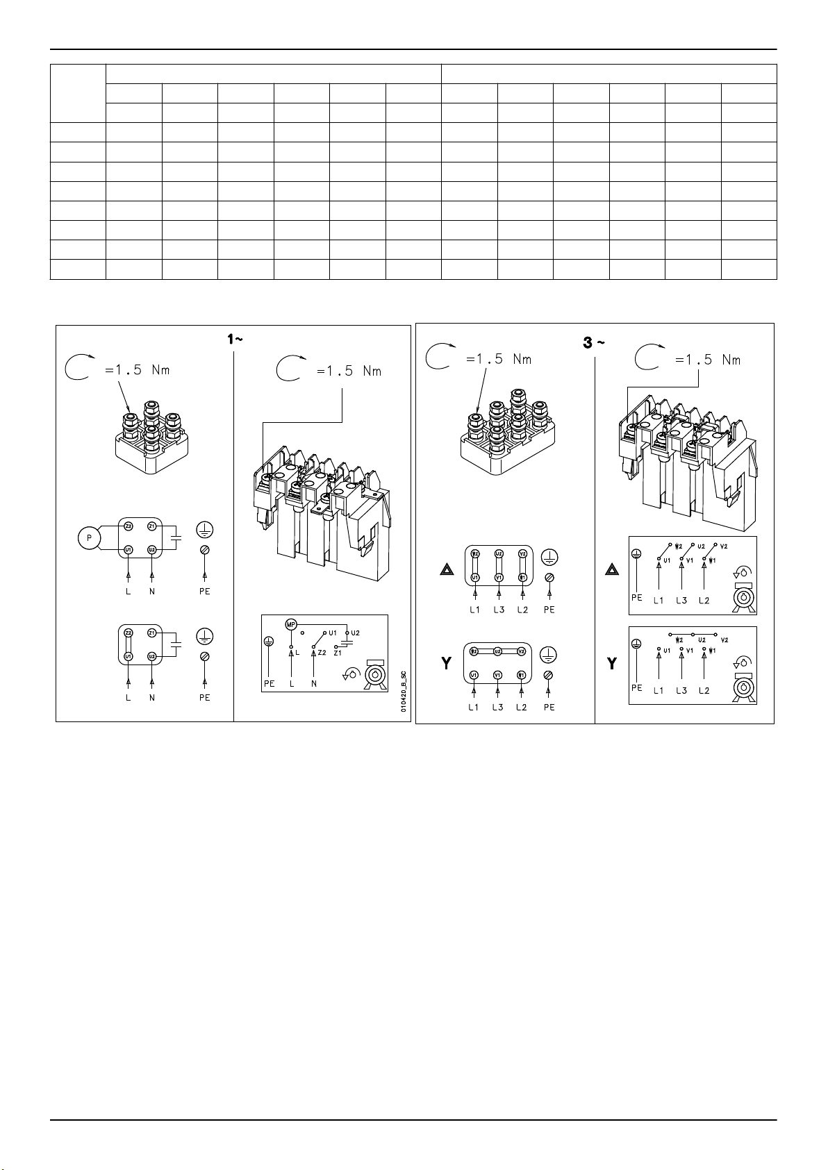
01042E_B_SC
it • en • fr • de • tr • ru
Dimen-
sioni
DN Fy
max
Fz
max
Fx
max
ƩF
max
ƩM
max
DN Fy
max
Fz
max
Fx
max
ƩF
max
ø [kN] [kN] [kN] [kN] [kNm] ø [kN] [kN] [kN] [kN] [kNm]
200-400 250 6,8 8,4 7,5 13,1 6,6 200 3,8 4,7 4,2 7,3 3,4
200-500 250 6,8 8,4 7,5 13,1 6,6 200 3,8 4,7 4,2 7,3 3,4
250-315 300 8,1 10,0 9,0 15,7 8,9 250 6,8 8,4 7,5 13,1 6,6
250-400 300 8,1 10,0 9,0 15,7 8,9 250 6,8 8,4 7,5 13,1 6,6
250-500 300 8,1 10,0 9,0 15,7 8,9 250 6,8 8,4 7,5 13,1 6,6
300-350 350 9,4 11,7 10,5 18,3 11,4 300 8,1 10,0 9,0 15,7 8,9
300-400 350 9,4 11,7 10,5 18,3 11,4 300 8,1 10,0 9,0 15,7 8,9
300-450 350 9,4 11,7 10,5 18,3 11,4 300 8,1 10,0 9,0 15,7 8,9
24.
Flangia di aspirazione Flangia di scarico
ƩM
max
e-NSC Installation, Operation, and Maintenance Manual 73
Page 74

it • en • fr • de • tr • ru
25.
100-160 - 150-400 150-500 - 300-450 100-160 - 150-400 150-500 - 300-450
Materiale corpo pompa C, D Materiale corpo pompa N, R
E Drenaggio G 3/8" G 1/2" G 3/8" G 1/2"
PM1 Scarico punto di presa
di pressione
CO1 Uscita circolazione G 1/4" *) G 1/2" *) G 1/4" *) G 1/2" *)
PM2 Aspirazione punto di
presa di pressione
F Punto di riempimento G 3/8" -- G 3/8" -T Sensore di temperatu-
ra
*) Opzionale su richiesta
G 1/4" G 1/2" G 1/4" G 1/2"
G 1/4" *) G 1/2" *) G 1/4" *) G 1/2" *)
-- G 1/2" *) -- G 1/2" *)
74 e-NSC Installation, Operation, and Maintenance Manual
Page 75

26.
1
2
3
1
3
2
it • en • fr • de • tr • ru
Italiano
1. Indicatore PM1
2. Tappo di scarico E
3. Tappo di riempimento F
Türkçe
1. Ölçek kapağı PM1
2. Boşaltma kapağı E
3. Doldurma kapağı F
27.
English
1. Gauge plug PM1
2. Drain plug E
3. Fill plug F
Русский
1. Контрольная заглушка PM1
2. Дренажная заглушка E
3. Заливная пробка F
Deutsch
1. Manometeranschlussstopfen PM1
2. Ablassschraube E
3. Füllstopfen F
Italiano
1. Indicatore PM1
2. Tappo di scarico E
3. Tappo di riempimento F
Türkçe
1. Ölçek kapağı PM1
2. Boşaltma kapağı E
3. Doldurma kapağı F
English
1. Gauge plug PM1
2. Drain plug E
3. Fill plug F
Русский
1. Контрольная заглушка PM1
2. Дренажная заглушка E
3. Заливная пробка F
Deutsch
1. Manometeranschlussstopfen PM1
2. Ablassschraube E
3. Füllstopfen F
e-NSC Installation, Operation, and Maintenance Manual 75
Page 76

it • en • fr • de • tr • ru
28.
Di-
men-
sioni
NSC1
00-160
NSC1
00-200
NSC1
00-250
NSC1
00-315
NSC1
00-400
NSC1
25-200
NSC1
25-250
NSC1
25-315
NSC1
25-400
NSC1
25-500
NSC1
50-200
NSC1
50-250
NSC1
50-315
NSC1
50-400
NSC1
50-500
NSC2
00-250
A / 922 B / 901.01
Staffa
del
cusci-
netto
ø [Nm] ø [Nm] ø [Nm] ø [Nm] ø [Nm] ø [Nm] ø [Nm] ø [Nm]
32 M24 x
1,5
32 M24 x
1,5
32 M24 x
1,5
32 M24 x
1,5
42 M30 x2180 M16 110 M12 60 M8 15 M12 60 M8 15 G 3/8" 35 G 1/4" 15
32 M24 x
1,5
32 M24 x
1,5
42 M30 x2180 M12 60 -- -- M8 15 M12 60 M8 15 G 3/8" 35 G 1/4" 15
42 M30 x2180 M16 110 M12 60 M8 15 M12 60 M8 15 G 3/8" 35 G 1/4" 15
60 M42 x3250 M20 200 M16 110 M10 25 M16 110 M8 15 G 1/2" 60 G 1/2" 60
32 M24 x
1,5
42 M30 x2180 M12 60 -- -- M8 15 M12 60 M8 15 G 3/8" 35 G 1/4" 15
42 M30 x2180 M12 60 -- -- M8 15 M12 60 M8 15 G 3/8" 35 G 1/4" 15
42 M30 x2180 M16 110 M12 60 M8 15 M12 60 M8 15 G 3/8" 35 G 1/4" 15
60 M42 x3250 M20 200 M16 110 M10 25 M16 110 M8 15 G 1/2" 60 G 1/2" 60
42 M30 x2180 M12 60 -- -- M8 15 M12 60 M8 15 G 1/2" 60 G 1/2" 60
920.01
130 M12 60 M12 60 M8 15 M12 60 M8 15 G 3/8" 35 G 1/4" 15
130 M12 60 -- -- M8 15 M12 60 M8 15 G 3/8" 35 G 1/4" 15
130 M12 60 -- -- M8 15 M12 60 M8 15 G 3/8" 35 G 1/4" 15
130 M12 60 M12 60 M8 15 M12 60 M8 15 G 3/8" 35 G 1/4" 15
130 M12 60 -- -- M8 15 M12 60 M8 15 G 3/8" 35 G 1/4" 15
130 M12 60 -- -- M8 15 M12 60 M8 15 G 3/8" 35 G 1/4" 15
130 M12 60 -- -- M8 15 M12 60 M8 15 G 3/8" 35 G 1/4" 15
C / 901.02
920.02
D / 901.03
901.06
G / 901.04 H / 901.05 E, F, T /
903.01, 903.04
CO1, PM1,
PM2 903.02, .
03, .05
76 e-NSC Installation, Operation, and Maintenance Manual
Page 77

it • en • fr • de • tr • ru
Di-
men-
sioni
NSC2
00-315
NSC2
00-400
NSC2
00-500
NSC2
50-315
NSC2
50-400
NSC2
50-500
NSC3
00-350
NSC3
00-400
NSC3
00-450
A / 920.1 Dado della girante • Impeller nut • Laufradmutter • Çark Somunu • Гайка крыльчатки
B / 901.01
920.01
C / 901.02
920.02
D / 901.03 Bullonatura copertura cuscinetto • Bearing cover bolting • Lagerdeckelverschraubung • Rulman kapak civatası • Болтовое
G / 901.04 Bullonatura piedi di supporto • Support foot bolting • Stützfußverschraubung • Destek ayağı civatası • Болтовое соединение
H / 901.05 Bullonatura protezione albero • Shaft guard bolting • Verschraubung der Wellenabdeckung • Mil koruma civatası • Болтовое
E, F, T / 903.01,
903.04
PM1, PM2, CO1
903.03, .02, .05
29.
del
cusci-
netto
ø [Nm] ø [Nm] ø [Nm] ø [Nm] ø [Nm] ø [Nm] ø [Nm] ø [Nm]
42 M30 x2180 M12 60 -- -- M8 15 M12 60 M8 15 G 1/2" 60 G 1/2" 60
60 M42 x3250 M16 110 -- -- M10 25 M16 110 M8 15 G 1/2" 60 G 1/2" 60
60 M42 x3250 M20 200 M16 110 M10 25 M16 110 M8 15 G 1/2" 60 G 1/2" 60
42 M30 x2180 M12 60 -- -- M8 15 M12 60 M8 15 G 1/2" 60 G 1/2" 60
60 M42 x3250 M16 110 -- -- M10 25 M16 110 M8 15 G 1/2" 60 G 1/2" 60
60 M42 x3250 M20 200 M16 110 M10 25 M16 110 M8 15 G 1/2" 60 G 1/2" 60
60 M42 x3250 M16 110 -- -- M10 25 M16 110 M8 15 G 1/2" 60 G 1/2" 60
60 M42 x3250 M16 110 -- -- M10 25 M16 110 M8 15 G 1/2" 60 G 1/2" 60
60 M42 x3250 M20 200 M16 110 M10 25 M16 110 M8 15 G 1/2" 60 G 1/2" 60
Bullonatura corpo pompa • Casing bolting • Gehäuse • Gövde civatalama • Болтовое соединение кожуха
Staffa cuscinetto - Bullonatura copertura corpo pompa • Bearing bracket - Casing cover bolting • Lagerträger - Gehäusedeckelverschraubung • Rulman mesnedi - Kutu kapak civatası • Кронштейн подшипника - болтовое соединение крышки кожуха
соединение крышки подшипника
основания опоры
соединение защиты вала
Tempo sensore temperatura, riempimento e scarico • Drain, filling and temperature sensor plug • Ablass-, Füll- und Temperatur-
sensorschraube • Boşaltma, doldurma ve sıcaklık sensör tapası • Заглушки отверстий дренажного, заливного и
температурного датчиков
Uscita circolazione e presa di pressione • Pressure tapping and circulation outlet • Druckentnahme- und Zirkulationsausgang •
Basınç itme ve devir çıkışı • Выходные патрубки отбора давления и линии циркуляции
920.01
A / 922 B / 901.01
Staffa
C / 901.02
920.02
D / 901.03
901.06
G / 901.04 H / 901.05 E, F, T /
903.01, 903.04
CO1, PM1,
PM2 903.02, .
03, .05
Dimensioni filetto [mm]
M12 60
M16 110
M20 200
M24 350
M27 530
Coppia di serraggio [Nm]
e-NSC Installation, Operation, and Maintenance Manual 77
Page 78

Page 79

Page 80

Xylem Service Italia S.r.l.
Via Vittorio Lombardi 14
Montecchio Maggiore VI 36075
Italy
Tel: (+39) 0444-707111
Fax: (+39) 0444-492166
©
2014 Xylem Inc
 Loading...