

ML507 QuickStart
May 2008

Overview
• Setup
• Boot with ACE-loader ACE File
• Observe LCD and Terminal messages
• Load new Configuration
• Re-load ACE-loader
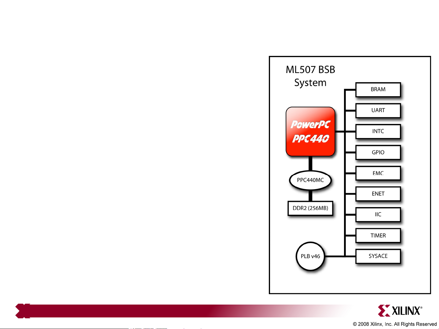
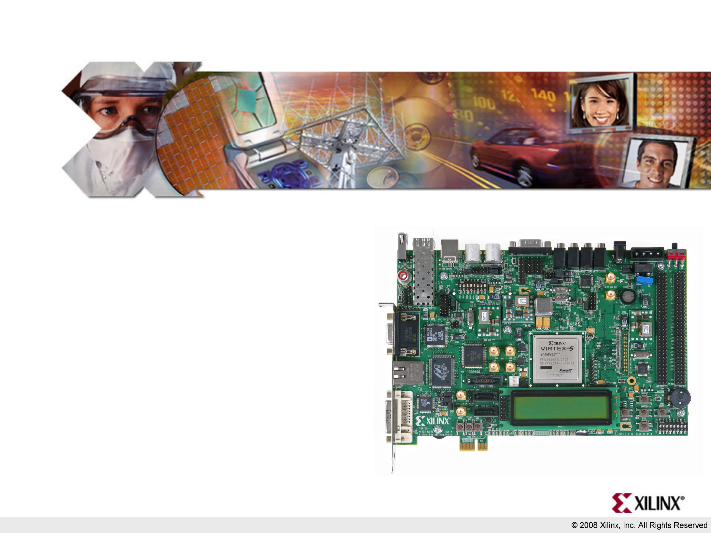
ML507 BSB Hardware
• The ML507 PPC440 design
hardware includes:
– PPC440MC DDR2 Interface
– External Memory Controller (EMC)
• ZBT SRAM
– BRAM
– Networking
– UART
– Interrupt Controller
– System ACE CF Interface
– GPIO (IIC, LEDs and LCD)
– PLB Arbiter
Note: Presentation applies to the ML507
Additional Setup Details
• Refer to ml505_overview_setup document for details on:
– Software Requirements
– ML507 Board Setup
• Equipment and Cables
• Software
• Network
– Terminal Programs
• This presentation requires the
9600-8-N-1 Baud terminal setup
Note: Presentation applies to the ML507
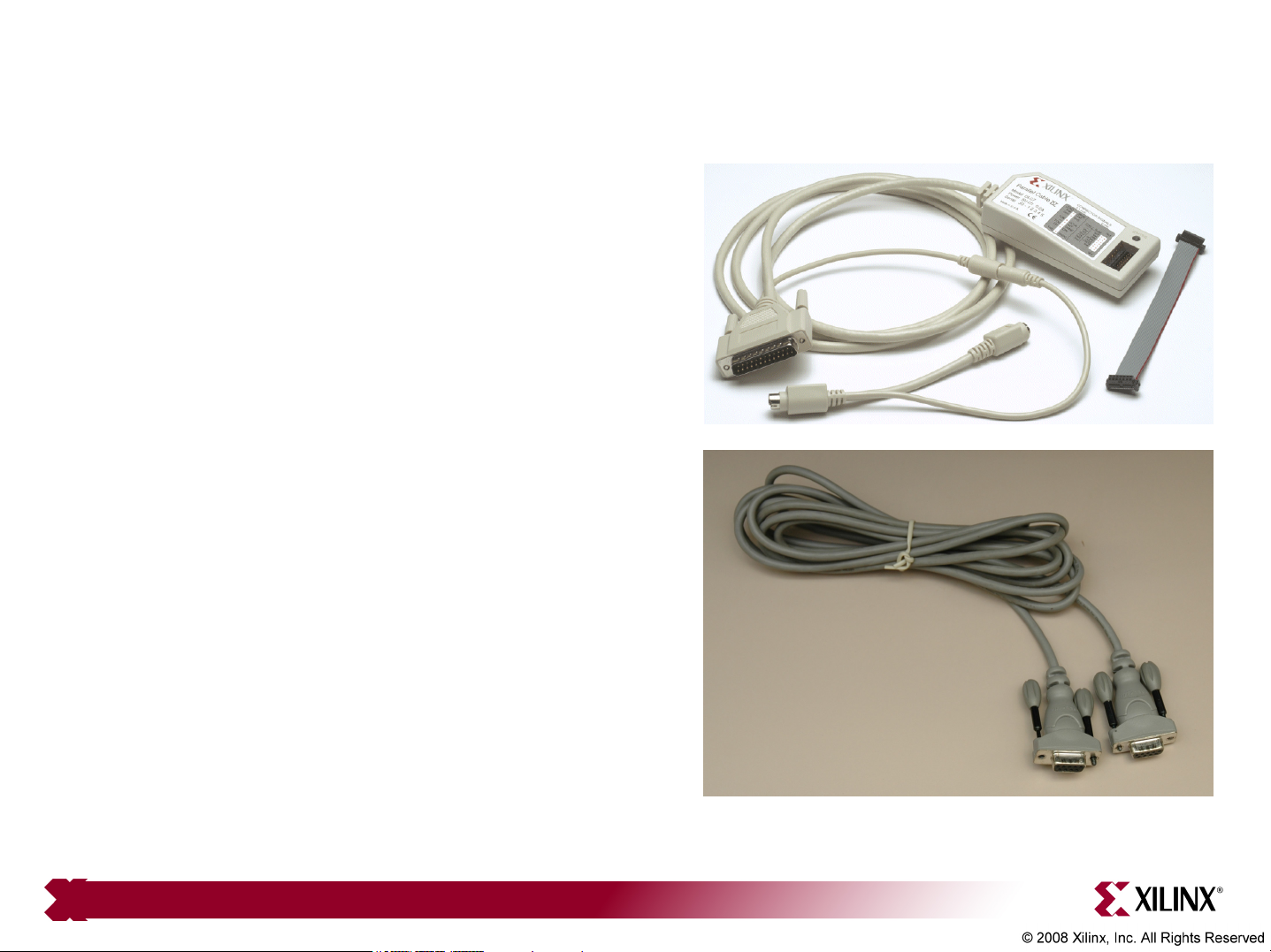
Hardware Setup
• Connect the Xilinx Parallel
Cable IV (PC4) to the
ML507 board
• Connect the RS232 null
modem cable to the
ML507 board
Note: Presentation applies to the ML507
Hardware Setup
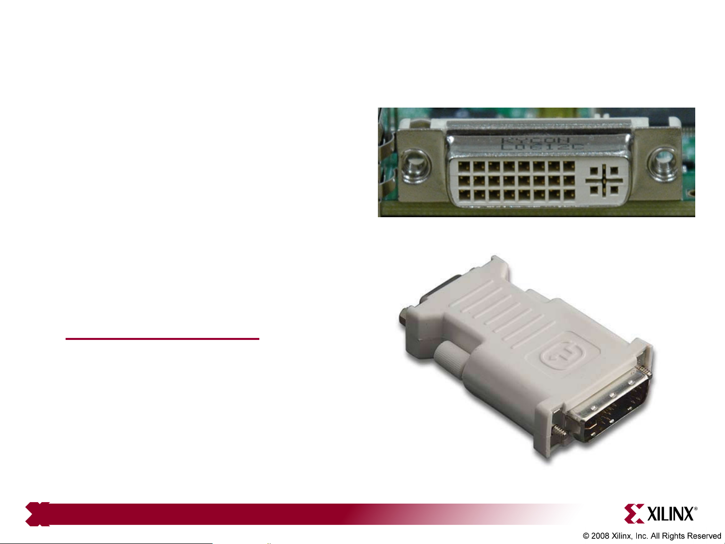
• The ML507 uses a DVI video
interface
• Connect a DVI monitor
or
• Use a DVI/VGA adapter
to connect a VGA monitor
– http://www.belkin.com
Note: Presentation applies to the ML507
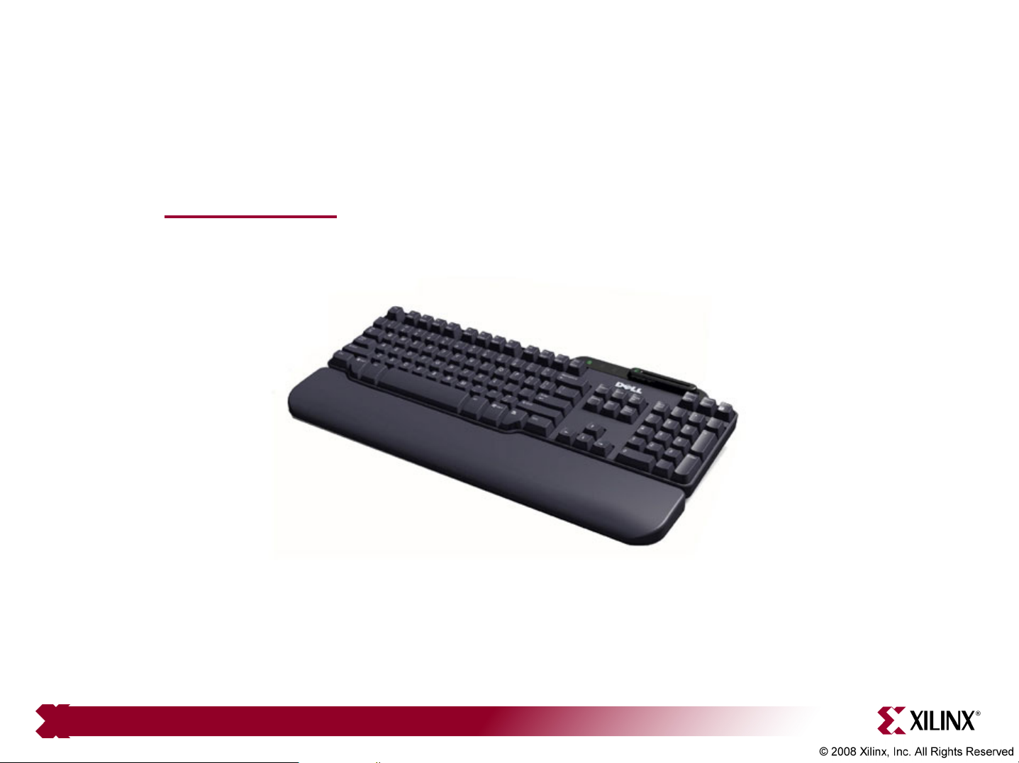
Hardware Setup
• USB Keyboard
– www.dell.com
Note: Presentation applies to the ML507

Factory CompactFlash
• The CompactFlash shipped with the ML507 board has the
following ace files preloaded:
Note: Presentation applies to the ML507
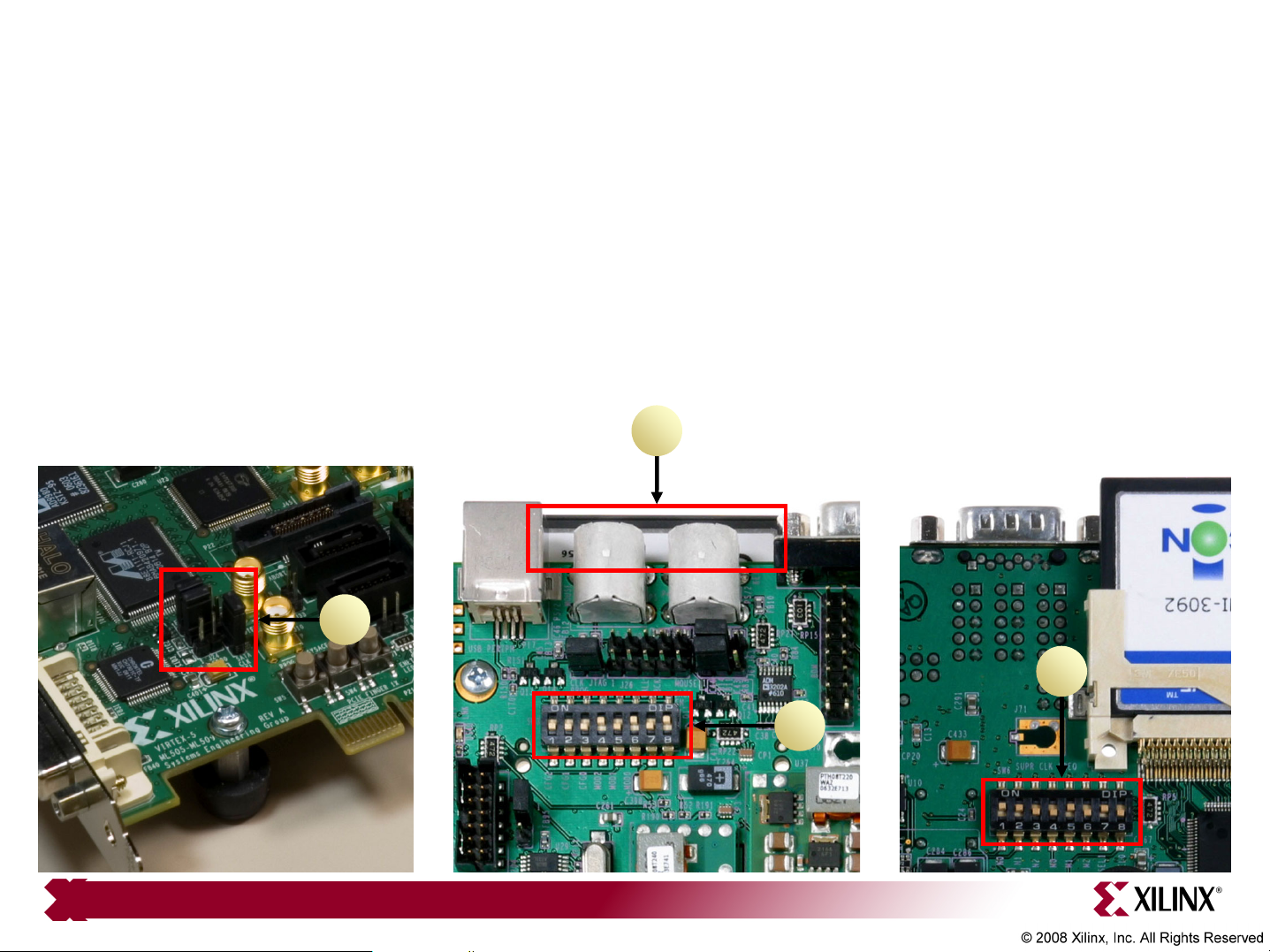
Verify Factory Default Settings
• Set the Ethernet PHY jumpers, J22, J23 to positions 1-2 (1)
• Insert the Factory CompactFlash into the ML507 board (2)
• Set the Front DIP switches (SW3) to 00010101 (1 = ON) (3)
• Set the Rear DIP switches (SW6) to 11001010 (4)
• Power-up the ML507 board
2
1
Note: Presentation applies to the ML507
4
3
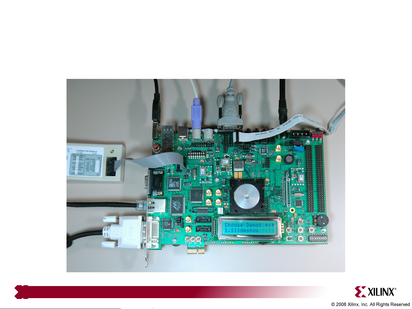
Bootload
• The bootload_video.ace loads:
Note: Presentation applies to the ML507
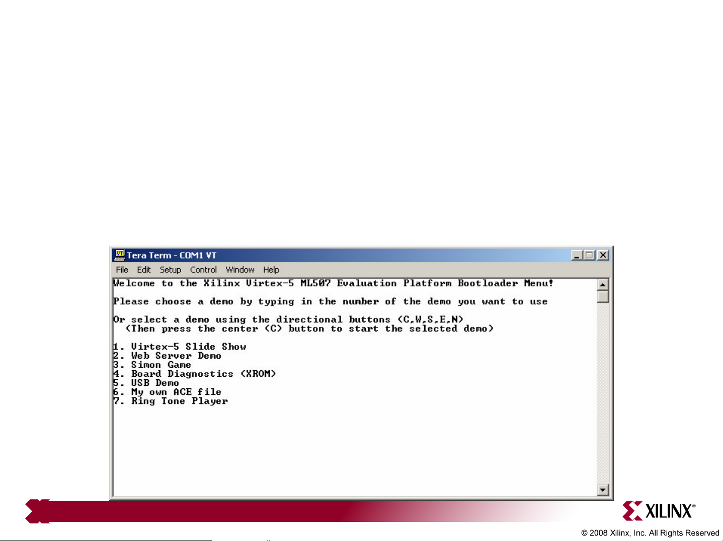
Bootload
• The terminal window also reflects the bootload application
• Use the left/center/right buttons to choose an application or type a
number in the terminal window
• After each demo, push the SysACE reset to return to bootload
Note: Presentation applies to the ML507

Slideshow
• Type 1, to launch the slideshow application in Configuration 1
• The slideshow loads the presentation into memory then presents it
Note: Presentation applies to the ML507

Slideshow
• The slideshow app will present a series of slides on the Monitor:
Note: Presentation applies to the ML507

Web Server
• Type 2, to launch the web server application in Configuration 2
– Note: You may need to turn off your browser's proxy and specify a direct
connection to the Internet in your browser options
Note: Host IP is 192.168.1.1, subnet mask is 255.255.255.0

Running the LWIP Demo
• Open a web browser to address 192.168.1.10
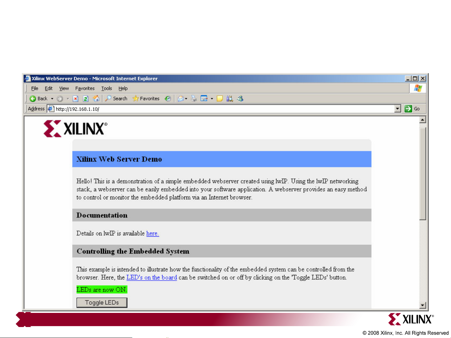
Running the LWIP Demo
• Click the Toggle LEDs button; view change on ML507
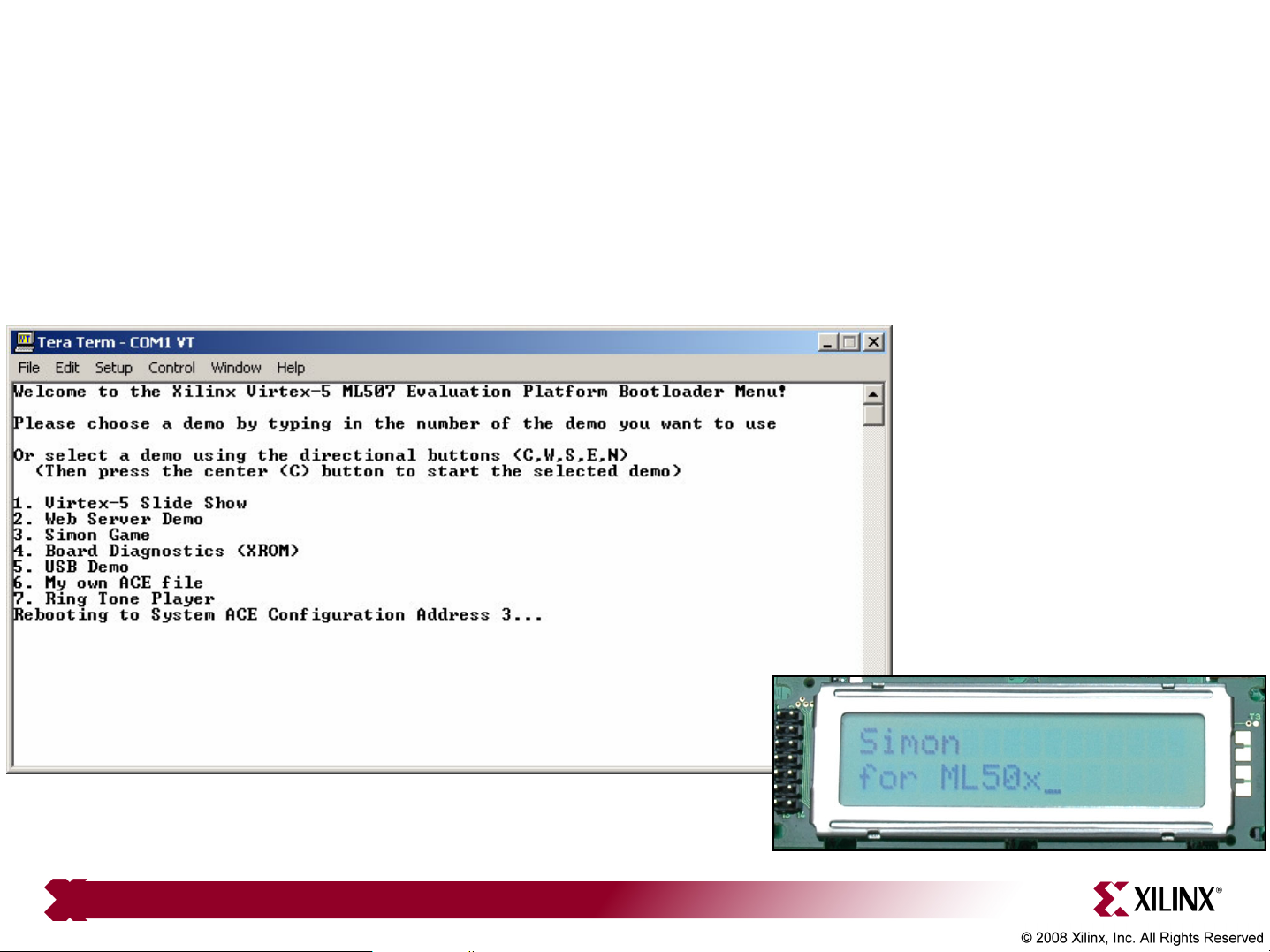
Simon
• Type 3, to launch the Simon application in Configuration 3
Note: Presentation applies to the ML507
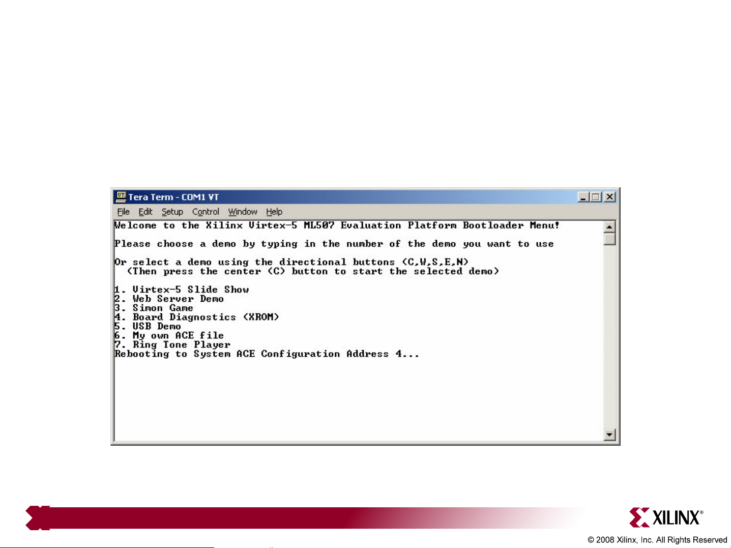
Board Diagnostics
• Type 4, to launch the XROM application in Configuration 4
Note: Presentation applies to the ML507
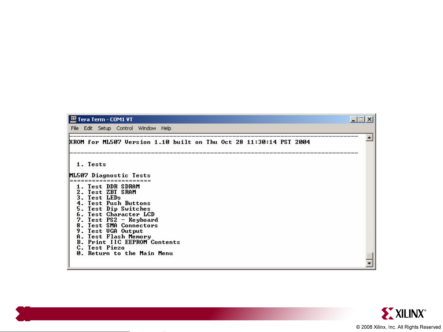
Board Diagnostics
• XROM includes a series of board test routines
Note: Presentation applies to the ML507
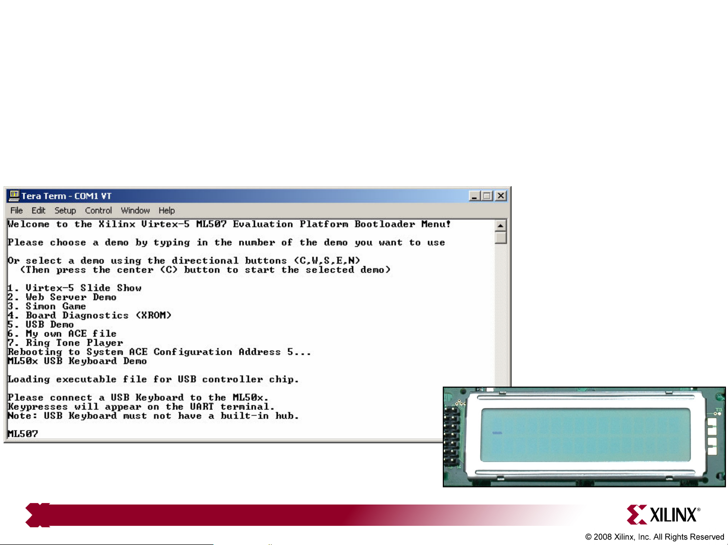
USB Keyboard
• Type 5, to launch the USB Keyboard application in Configuration 5
• Type ML507 and view results:
Note: Attach keyboard after demo loads

My ACE
• Type 6, to launch the My ACE application in Configuration 6
Note: Presentation applies to the ML507
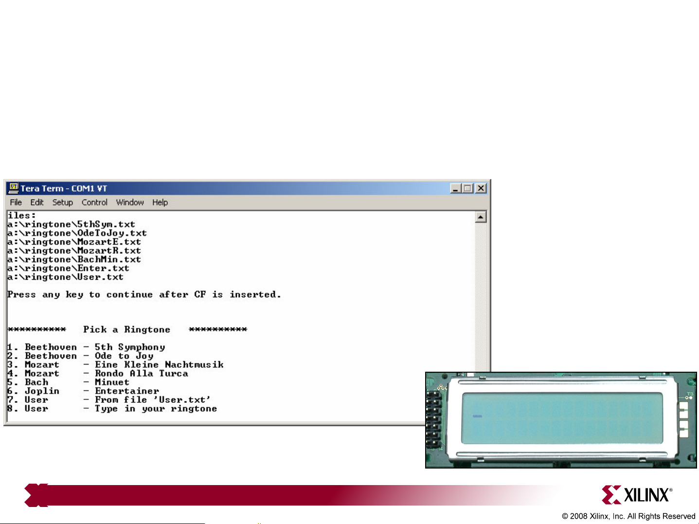
Ringtone
• Type 7, to launch the Ringtone application in Configuration 7
• Press any key then press 1-7 to play a simple melody
Note: Presentation applies to the ML507

• Virtex-5
– Silicon Devices
http://www.xilinx.com/products/silicon_solutions
– Virtex-5 Multi-Platform FPGA
http://www.xilinx.com/products/silicon_solutions/fpgas/virtex/virtex5
– Virtex-5 Family Overview: LX, LXT, SXT, and FXT Platforms
http://www.xilinx.com/support/documentation/data_sheets/ds100.pdf
– Virtex-5 FPGA DC and Switching Characteristics Data Sheet
http://www.xilinx.com/support/documentation/data_sheets/ds202.pdf
Documentation

• Virtex-5
– Virtex-5 FPGA User Guide
http://www.xilinx.com/support/documentation/user_guides/ug190.pdf
– Virtex-5 FPGA Configuration User Guide
http://www.xilinx.com/support/documentation/user_guides/ug191.pdf
– Virtex-5 System Monitor User Guide
http://www.xilinx.com/support/documentation/user_guides/ug192.pdf
– Virtex-5 Packaging and Pinout Specification
http://www.xilinx.com/support/documentation/user_guides/ug195.pdf
Documentation

Documentation
• Virtex-5 RocketIO
– RocketIO GTP Transceivers
http://www.xilinx.com/products/silicon_solutions/fpgas/virtex/virtex5/
capabilities/RocketIO_GTP.htm
– RocketIO GTX Transceivers
http://www.xilinx.com/products/silicon_solutions/fpgas/virtex/virtex5/
capabilities/RocketIO_GTX.htm
– RocketIO GTP Transceiver User Guide – UG196
http://www.xilinx.com/support/documentation/user_guides/ug196.pdf
– RocketIO GTX Transceiver User Guide – UG198
http://www.xilinx.com/support/documentation/user_guides/ug198.pdf

Documentation
• Design Resources
– ISE Development Tools and IP
http://www.xilinx.com/ise
– Integrated Software Environment (ISE) Foundation Resources
http://www.xilinx.com/ise/logic_design_prod/foundation.htm
– ISE Manuals
http://www.xilinx.com/support/software_manuals.htm
– ISE Development System Reference Guide
http://toolbox.xilinx.com/docsan/xilinx10/books/docs/dev/dev.pdf
– ISE Development System Libraries Guide
http://toolbox.xilinx.com/docsan/xilinx10/books/docs/virtex5_hdl/virtex5_hdl.pdf

Documentation
• Additional Design Resources
– Customer Support
http://www.xilinx.com/support
– Xilinx Design Services:
http://www.xilinx.com/xds
– Titanium Dedicated Engineering:
http://www.xilinx.com/titanium
– Education Services:
http://www.xilinx.com/education
– Xilinx On Board (Board and kit locator):
http://www.xilinx.com/xob

• Platform Studio
– Embedded Development Kit (EDK) Resources
http://www.xilinx.com/edk
– Embedded System Tools Reference Manual
http://www.xilinx.com/support/documentation/sw_manuals/edk10_est_rm.pdf
– EDK Concepts, Tools, and Techniques
http://www.xilinx.com/ise/embedded/edk92i_docs/edk_ctt.pdf
Documentation

• MicroBlaze
– MicroBlaze Processor
http://www.xilinx.com/microblaze
– MicroBlaze Processor Reference Guide – UG081
http://www.xilinx.com/support/documentation/sw_manuals/mb_ref_guide.pdf
Documentation

Documentation
• Memory Solutions
– Demos on Demand – Memory Interface Solutions with Xilinx FPGAs
http://www.demosondemand.com/clients/xilinx/001/page_new2/index.asp#35
– Xilinx Memory Corner
http://www.xilinx.com/products/design_resources/mem_corner
– Additional Memory Resources
http://www.xilinx.com/support/software/memory/protected/index.htm
– Xilinx Memory Interface Generator (MIG) 2.1 User Guide
http://www.xilinx.com/support/software/memory/protected/ug086.pdf
– Memory Interfaces Made Easy with Xilinx FPGAs and the
Memory Interface Generator
http://www.xilinx.com/support/documentation/white_papers/wp260.pdf

• Ethernet
– Virtex-5 Embedded Tri-Mode Ethernet MAC Wrapper Data Sheet
http://www.xilinx.com/support/documentation/ip_documentation/
v5_emac_ds550.pdf
– Virtex-5 Embedded Tri-Mode Ethernet MAC Wrapper Getting Started Guide
http://www.xilinx.com/support/documentation/ip_documentation/
v5_emac_gsg340.pdf
– Virtex-5 Tri-Mode Ethernet Media Access Controller User Guide
http://www.xilinx.com/support/documentation/user_guides/ug194.pdf
Documentation
– LightWeight IP (lwIP) Application Examples – XAPP1026
http://www.xilinx.com/support/documentation/application_notes/xapp1026.pdf

Documentation
• ML505/506/507
– ML505 Overview
http://www.xilinx.com/ml505
– ML506 Overview
http://www.xilinx.com/ml506
– ML507 Overview
http://www.xilinx.com/ml507
– ML505/506/507 Evaluation Platform User Guide – UG347
http://www.xilinx.com/support/documentation/boards_and_kits/ug347.pdf
– ML505/506/507 Getting Started Tutorial – UG348
http://www.xilinx.com/support/documentation/boards_and_kits/ug348.pdf
– ML505/506/507 Reference Design User Guide – UG349
http://www.xilinx.com/support/documentation/boards_and_kits/ug349.pdf

Documentation
• ML505/506/507
– ML505/506/507 Schematics
http://www.xilinx.com/support/documentation/boards_and_kits/
ml50x_schematics.pdf
– ML505/506/507 Bill of Material
http://www.xilinx.com/support/documentation/boards_and_kits/
ml505_501_bom.xls
 Loading...