


by 


Xantrex PRO Inverter
XM 1000 and XM 1800
t1-800-670-0707 (toll-free in North America) 1-360-925-5097 (direct)
f 1-360-925-5143 (direct)
e CustomerService@xantrex.com www.xantrex.com
975-0263-01-01 REV. C |
Printed in China |
Owner's Guide

Xantrex PRO Inverter
Owner’s Guide

About Xantrex
Xantrex Technology Inc. is a world-leading supplier of advanced power electronics and controls with products from 50 watt mobile units to 1 MW utility-scale systems for wind, solar, batteries, fuel cells, microturbines, and backup power applications in both grid-connected and stand-alone systems. Xantrex products include inverters, battery chargers, programmable power supplies, and variable speed drives that convert, supply, control, clean, and distribute electrical power.
Trademarks
Xantrex PRO Inverter is a trademark of Xantrex International. Xantrex is a registered trademark of Xantrex International.
Other trademarks, registered trademarks, and product names are the property of their respective owners and are used herein for identification purposes only.
Notice of Copyright
Xantrex PRO Inverter Owner’s Guide © February 2007 Xantrex International. All rights reserved.
Disclaimer
UNLESS SPECIFICALLY AGREED TO IN WRITING, XANTREX TECHNOLOGY INC. (“XANTREX”)
(a)MAKES NO WARRANTY AS TO THE ACCURACY, SUFFICIENCY OR SUITABILITY OF ANY TECHNICAL OR OTHER INFORMATION PROVIDED IN ITS MANUALS OR OTHER DOCUMENTATION.
(b)ASSUMES NO RESPONSIBILITY OR LIABILITY FOR LOSS OR DAMAGE, WHETHER DIRECT, INDIRECT, CONSEQUENTIAL OR INCIDENTAL, WHICH MIGHT ARISE OUT OF THE USE OF SUCH INFORMATION. THE USE OF ANY SUCH INFORMATION WILL BE ENTIRELY AT THE USER’S RISK.
Date and Revision
February 2007 Revision C
Manual Part Number
975-0263-01-01
Product Part Numbers
806-1010 (XM 1000)
806-1810 (XM 1800)
Contact Information
Telephone: 1 800 670 0707 (toll-free in North America) 1 360 925 5097 (direct)
Fax: |
1 360 925 5143 (direct) |
Email: |
customerservice@xantrex.com |
Web: |
www.xantrex.com |

About This Guide
Purpose
The purpose of this Owner’s Guide is to provide explanations and procedures for installing, operating, and maintaining the Xantrex PRO Inverter (XM 1800 and XM 1000).
Scope
The Guide provides safety guidelines, detailed planning and setup information, procedures for installing the inverter, as well as information about operating and troubleshooting the installation. It does not provide details about particular brands of batteries. You need to consult individual battery manufacturers for this information.
Audience
The Guide is intended for anyone who needs to install and operate the Xantrex PRO Inverter. Because installation requires compliance with applicable electrical codes, installers should be certified technicians or electricians.
iii
About This Guide
Conventions Used
The following conventions are used in this guide.
WARNING
Warnings identify conditions that could result in personal injury or loss of life
CAUTION
Cautions identify conditions or practices that could result in damage to the unit or other equipment.
Important: These notes describe things which are important for you to know, but not as serious as a caution or warning.
Related Information
You can find more information about Xantrex Technology Inc. and its products and services at www.xantrex.com.
iv |
975-0263-01-01 |
Important Safety Instructions
WARNING
This chapter contains important safety and operating instructions. Read and keep this Owner’s Guide for future reference.
1.Before installing and using the Xantrex PRO Inverter (XM 1800 or XM 1000), read all instructions and cautionary markings on the inverter, the batteries, and all appropriate sections of this guide.
2.Do not expose the Xantrex PRO Inverter to rain, snow, or spray. To reduce risk of fire hazard, do not cover or obstruct the ventilation openings. Do not install the inverter in a zero-clearance compartment. Overheating may result.
3.Use only attachments recommended or sold by the manufacturer. Doing otherwise may result in a risk of fire, electric shock, or injury to persons.
4.To avoid a risk of fire and electric shock, make sure that existing wiring is in good condition and that wire is not undersized. Do not operate the inverter with damaged or substandard wiring.
5.Do not operate the inverter if it has received a sharp blow, been dropped, or otherwise damaged in any way. If the inverter is damaged, see the Warranty section.
6.Do not disassemble the inverter. It contains no user-serviceable parts. See Warranty for instructions on obtaining service. Attempting to service the inverter yourself may result in a risk of electrical shock or fire. Internal capacitors remain charged after all power is disconnected.
7.To reduce the risk of electrical shock, disconnect both AC and DC power from the inverter before attempting any maintenance or cleaning or working on any circuits connected to the inverter. Turning off controls will not reduce this risk.
8.The inverter must be provided with an equipment-grounding conductor connected to the AC input ground.
v
Safety
WARNING: Risk of injury or loss of life
Do not use Xantrex PRO Inverter in connection with life support systems or other medical equipment or devices.
Explosive Gas Precautions
 WARNING: Explosion hazard
1.Working in the vicinity of lead-acid batteries is dangerous. Batteries generate explosive gases during normal operation. Therefore, you must read this guide and follow the instructions exactly before installing or using your Xantrex PRO Inverter.
2.This equipment contains components that tend to produce arcs or sparks. To prevent fire or explosion, do not install the inverter in compartments containing batteries or flammable materials, or in locations that require ignition-protected equipment. This includes any space containing gasoline-powered machinery, fuel tanks, as well as joints, fittings, or other connections between components of the fuel system.
3.To reduce the risk of battery explosion, follow these instructions and those published by the battery manufacturer and the manufacturer of the equipment in which the battery is installed.
vi |
975-0263-01-01 |

Safety
Precautions When Working With Batteries
 WARNING: Explosion or fire hazard
1.Follow all instructions published by the battery manufacturer and the manufacturer of the equipment in which the battery is installed.
2.Make sure the area around the battery is well ventilated.
3.Never smoke or allow a spark or flame near the engine or batteries.
4.Use caution to reduce the risk of dropping a metal tool on the battery. It could spark or short circuit the battery or other electrical parts and could cause an explosion.
5.Remove all metal items, like rings, bracelets, and watches when working with lead-acid batteries. Lead-acid batteries produce a short circuit current high enough to weld metal to skin, causing a severe burn.
6.Have someone within range of your voice or close enough to come to your aid when you work near a lead-acid battery.
7.Have plenty of fresh water and soap nearby in case battery acid contacts skin, clothing, or eyes.
8.Wear complete eye protection and clothing protection. Avoid touching your eyes while working near batteries.
9.If battery acid contacts skin or clothing, wash immediately with soap and water. If acid enters your eye, immediately flood it with running cold water for at least twenty minutes and get medical attention immediately.
10.If you need to remove a battery, always remove the ground terminal from the battery first. Make sure all accessories are off so you don’t cause a spark.
975-0263-01-01 |
vii |

Safety
Precautions for Using Rechargeable Appliances
CAUTION: Equipment damage
The output of the inverter is non-sinusoidal.
Most rechargeable battery-operated equipment uses a separate charger or transformer that is plugged into an AC receptacle and produces a low voltage charging output.
Some chargers for small rechargeable batteries can be damaged if connected to the Xantrex PRO Inverter. Do not use the following with the inverter:
•Small battery-operated appliances like flashlights, razors, and night lights that can be plugged directly into an AC receptacle to recharge.
•Some chargers for battery packs used in power hand tools. These affected chargers display a warning label stating that dangerous voltages are present at the battery terminals.
If you are unsure about using your rechargeable appliance with the inverter, contact the equipment manufacturer to determine the rechargeable appliance’s compatibility with the modified sinewave (nonsinusoidal) AC waveform.
viii |
975-0263-01-01 |

Contents
Important Safety Instructions - - - - - - - - - - - - - - - - - - - - - - - - - - - - - - - - - - -v
1 Introduction
Quality Power - - - - - - - - - - - - - - - - - - - - - - - - - - - - - - - - - - - - - - - - - - - - - - - - 1–1
Comprehensive Protection - - - - - - - - - - - - - - - - - - - - - - - - - - - - - - - - - - - - - - - - 1–2
2 Features
Materials List- - - - - - - - - - - - - - - - - - - - - - - - - - - - - - - - - - - - - - - - - - - - - - - - - 2–1
Front Panel - - - - - - - - - - - - - - - - - - - - - - - - - - - - - - - - - - - - - - - - - - - - - - - - - - 2–2
Side View - - - - - - - - - - - - - - - - - - - - - - - - - - - - - - - - - - - - - - - - - - - - - - - - - - - 2–2
Rear Panel - - - - - - - - - - - - - - - - - - - - - - - - - - - - - - - - - - - - - - - - - - - - - - - - - - - 2–3
3 Installation
Designing Your Installation - - - - - - - - - - - - - - - - - - - - - - - - - - - - - - - - - - - - - - - 3–1 Installation Codes - - - - - - - - - - - - - - - - - - - - - - - - - - - - - - - - - - - - - - - - - - - 3–4 Calculating Battery Requirements - - - - - - - - - - - - - - - - - - - - - - - - - - - - - - - - 3–4 Choosing an Effective Charging System - - - - - - - - - - - - - - - - - - - - - - - - - - - 3–4 Choosing an Appropriate Location - - - - - - - - - - - - - - - - - - - - - - - - - - - - - - - 3–5 Calculating Cable Sizes - - - - - - - - - - - - - - - - - - - - - - - - - - - - - - - - - - - - - - - 3–6
Calculating Size of DC Input Cables - - - - - - - - - - - - - - - - - - - - - - - - - - - 3–6 Sizing the Chassis Ground Cable - - - - - - - - - - - - - - - - - - - - - - - - - - - - - - 3–7 Calculating Fuse/Circuit Breaker Size - - - - - - - - - - - - - - - - - - - - - - - - - - - - - 3–8 Installing the XM 1800 - - - - - - - - - - - - - - - - - - - - - - - - - - - - - - - - - - - - - - - - - - 3–9 Safety Instructions - - - - - - - - - - - - - - - - - - - - - - - - - - - - - - - - - - - - - - - - - - 3–9 Installation Tools and Materials - - - - - - - - - - - - - - - - - - - - - - - - - - - - - - - - - 3–9 Overview of Installation Steps - - - - - - - - - - - - - - - - - - - - - - - - - - - - - - - - - 3–11 Mounting the Inverter - - - - - - - - - - - - - - - - - - - - - - - - - - - - - - - - - - - - - - - 3–11 Connecting the Chassis Ground - - - - - - - - - - - - - - - - - - - - - - - - - - - - - - - - 3–12 Grounding Locations - - - - - - - - - - - - - - - - - - - - - - - - - - - - - - - - - - - - - 3–12 Chassis Ground Stud - - - - - - - - - - - - - - - - - - - - - - - - - - - - - - - - - - - - - 3–13 AC Wiring- - - - - - - - - - - - - - - - - - - - - - - - - - - - - - - - - - - - - - - - - - - - - - - - - - 3–14 Connecting AC Input - - - - - - - - - - - - - - - - - - - - - - - - - - - - - - - - - - - - - - - 3–15 Connecting AC Output to an Existing AC Circuit - - - - - - - - - - - - - - - - - - - - 3–17
975-0263-01-01 |
ix |
Contents
Connecting the DC Cables - - - - - - - - - - - - - - - - - - - - - - - - - - - - - - - - - - - - - - - 3–22
Testing Your Installation - - - - - - - - - - - - - - - - - - - - - - - - - - - - - - - - - - - - - - - - 3–24
Testing in Invert Mode - - - - - - - - - - - - - - - - - - - - - - - - - - - - - - - - - - - - - - 3–24
Testing in Shore Power Mode - - - - - - - - - - - - - - - - - - - - - - - - - - - - - - - - - 3–25
Installing the Remote Panel - - - - - - - - - - - - - - - - - - - - - - - - - - - - - - - - - - - - - - 3–26
4 Operation
Front Panel Operation - - - - - - - - - - - - - - - - - - - - - - - - - - - - - - - - - - - - - - - - - - - 4–2
Operating in Shore Power Mode - - - - - - - - - - - - - - - - - - - - - - - - - - - - - - - - - - - - 4–3
Operating in Inverter Mode - - - - - - - - - - - - - - - - - - - - - - - - - - - - - - - - - - - - - - - 4–3
Turning the Inverter On and Off - - - - - - - - - - - - - - - - - - - - - - - - - - - - - - - - - 4–3
Checking Battery Status - - - - - - - - - - - - - - - - - - - - - - - - - - - - - - - - - - - - - - 4–4
Checking Output Power - - - - - - - - - - - - - - - - - - - - - - - - - - - - - - - - - - - - - - 4–4
Operating Several Loads at Once - - - - - - - - - - - - - - - - - - - - - - - - - - - - - - - - 4–4
Turning the Inverter Off When Not Used - - - - - - - - - - - - - - - - - - - - - - - - - - - 4–4
Operating Limits - - - - - - - - - - - - - - - - - - - - - - - - - - - - - - - - - - - - - - - - - - - - - - 4–5
Power Output - - - - - - - - - - - - - - - - - - - - - - - - - - - - - - - - - - - - - - - - - - - - - 4–5
Input Voltage - - - - - - - - - - - - - - - - - - - - - - - - - - - - - - - - - - - - - - - - - - - - - 4–5
Inverter Loads - - - - - - - - - - - - - - - - - - - - - - - - - - - - - - - - - - - - - - - - - - - - - - - - 4–6
Overload Conditions - - - - - - - - - - - - - - - - - - - - - - - - - - - - - - - - - - - - - - - - 4–6
High Surge Loads - - - - - - - - - - - - - - - - - - - - - - - - - - - - - - - - - - - - - - - - - - 4–6
Trouble Loads - - - - - - - - - - - - - - - - - - - - - - - - - - - - - - - - - - - - - - - - - - - - - 4–6
Over-temperature Conditions - - - - - - - - - - - - - - - - - - - - - - - - - - - - - - - - - - - - - - 4–7
Routine Maintenance - - - - - - - - - - - - - - - - - - - - - - - - - - - - - - - - - - - - - - - - - - - 4–7
XM 1800 Unit - - - - - - - - - - - - - - - - - - - - - - - - - - - - - - - - - - - - - - - - - - - - - 4–7
Batteries - - - - - - - - - - - - - - - - - - - - - - - - - - - - - - - - - - - - - - - - - - - - - - - - - 4–7
5 Troubleshooting
Common Problems - - - - - - - - - - - - - - - - - - - - - - - - - - - - - - - - - - - - - - - - - - - - - 5–2
Buzz in Audio Equipment - - - - - - - - - - - - - - - - - - - - - - - - - - - - - - - - - - - - - 5–2
Television Reception - - - - - - - - - - - - - - - - - - - - - - - - - - - - - - - - - - - - - - - - 5–2
Understanding Fault Codes - - - - - - - - - - - - - - - - - - - - - - - - - - - - - - - - - - - - - - - 5–2
Troubleshooting Reference - - - - - - - - - - - - - - - - - - - - - - - - - - - - - - - - - - - - - - - 5–4
x |
975-0263-01-01 |

Contents
A Specifications
Electrical Performance - - - - - - - - - - - - - - - - - - - - - - - - - - - - - - - - - - - - - - - - - A–1
Physical Specifications - - - - - - - - - - - - - - - - - - - - - - - - - - - - - - - - - - - - - - - - - A–2
Mounting Dimensions - - - - - - - - - - - - - - - - - - - - - - - - - - - - - - - - - - - - - - - - - - A–3
B Battery Types
Battery Types- - - - - - - - - - - - - - - - - - - - - - - - - - - - - - - - - - - - - - - - - - - - - - - - -B–1
Automotive Starting Batteries - - - - - - - - - - - - - - - - - - - - - - - - - - - - - - - - - -B–1
Deep-Cycle Batteries - - - - - - - - - - - - - - - - - - - - - - - - - - - - - - - - - - - - - - - -B–2
Battery Size - - - - - - - - - - - - - - - - - - - - - - - - - - - - - - - - - - - - - - - - - - - - - - - - - -B–2
Estimating Battery Requirements - - - - - - - - - - - - - - - - - - - - - - - - - - - - - - - - - - -B–4
Battery Sizing Example - - - - - - - - - - - - - - - - - - - - - - - - - - - - - - - - - - - - - - -B–4
Battery Sizing Worksheet - - - - - - - - - - - - - - - - - - - - - - - - - - - - - - - - - - - - -B–5
Using Multiple Batteries - - - - - - - - - - - - - - - - - - - - - - - - - - - - - - - - - - - - - - - - -B–6
Two Batteries Connected In Parallel - - - - - - - - - - - - - - - - - - - - - - - - - - - - - -B–6
Two Separate Battery Banks - - - - - - - - - - - - - - - - - - - - - - - - - - - - - - - - - - -B–6
Battery Tips - - - - - - - - - - - - - - - - - - - - - - - - - - - - - - - - - - - - - - - - - - - - - - - - - -B–7
C Alternators and Charging Systems
Charging System Requirements - - - - - - - - - - - - - - - - - - - - - - - - - - - - - - - - - - - -C–1
Charging With an Engine Alternator - - - - - - - - - - - - - - - - - - - - - - - - - - - - - - - - -C–2
Using a Standard Vehicle Alternator - - - - - - - - - - - - - - - - - - - - - - - - - - - - - -C–2
Using a Multi-stage Alternator Regulator - - - - - - - - - - - - - - - - - - - - - - - - - - -C–2
Using a High-Output Alternator - - - - - - - - - - - - - - - - - - - - - - - - - - - - - - - - -C–2
Charging From AC Power - - - - - - - - - - - - - - - - - - - - - - - - - - - - - - - - - - - - - - - -C–3
Charging From Alternative Energy Sources - - - - - - - - - - - - - - - - - - - - - - - - - - - -C–3
Warranty and Return Information - - - - - - - - - - - - - - - - - - - - - - - - - - - WA–1
975-0263-01-01 |
xi |

xii

1 Introduction
Congratulations on your purchase of the Xantrex PRO Inverter (XM 1800 or XM 1000). The XM 1800 has been designed to give you quality power, ease of use, and reliability.
Please take a few moments to read this chapter to familiarize yourself with the main performance features and protection features of the XM 1800.
Quality Power
The XM 1800 is a quality inverter designed for recreational vehicle (RV) electrical systems that have a battery charger or generator already installed.
•The XM 1800 provides up to 1800 watts (XM 1800) or up to 1000 watts (XM 1000) of continuous modified sine wave power from a battery bank. It is designed to handle loads such as 1000 watt (XM 1800) or 600 watt (XM 1000) microwaves, TVs, VCRs, and midsized power tools.
•The XM 1800’s high surge capability lets you handle many hard-to- start loads, including large TVs and small refrigerators.
•The built-in transfer switch automatically transfers between inverter power and incoming AC power (shore power) to ensure power is always available.
•A built-in 15 A supplementary circuit breaker protects the XM 1800 from overload conditions to the GFCI receptacles.
•The XM 1800’s low standby battery demand means you don’t have to worry about excessive drain on your battery if you leave the inverter on for a few days. When the XM 1800 is on but no power is being supplied to a load, the inverter draws, on average, less than 0.5 A (XM 1000) or less than 0.7 A (XM 1800) from the battery.
•The cooling fan in the XM 1800 is both load activated and thermally activated. The fan turns off automatically after the inverter has cooled or the load has decreased.
1–1

Introduction
Comprehensive Protection
The XM 1800 is equipped with numerous protection features to guarantee safe and trouble-free operation:
Low battery alarm Alerts you if the battery has become discharged to 11.0 V or lower.
Low battery voltage shutdown Shuts the XM 1800 down automatically if the battery voltage drops below 10.5 V. This feature protects the battery from being completely discharged.
High battery voltage shutdown Shuts the XM 1800 down automatically if the input voltage rises to 15.5 V or more.
Overload alarm Alerts you if the loads connected to the XM 1800 are close to the inverter’s operating limits.
Overload shutdown Shuts the XM 1800 down automatically if the loads connected to the inverter exceed the inverter’s operating limits or if a short circuit is detected in the circuitry connected to the inverter’s output.
Over-temperature alarm Alerts you if the XM 1800 is running hot and is approaching the over-temperature shutdown level.
Over temperature shutdown Shuts the XM 1800 down automatically if its internal temperature rises above an acceptable level.
These values and thresholds are set at the factory and cannot be adjusted.
1–2 |
975-0263-01-01 |

2 Features
Chapter 2 describes the main features of the XM 1800.
Xantrex recommends that you familiarize yourself with these features before installing and operating the inverter.
Materials List
Your XM 1800 package includes:
•One XM 1800 inverter
•Two M8 lock washers (on the DC input cable terminals)
•Two M8 nuts (on the DC input cable terminals)
•Two strain reliefs for AC input and output wiring
•Two rubberized input terminal covers
•Owner’s Guide.
If any of these materials are missing or are unsatisfactory in any way, please contact Customer Service. Contact information is available on page WA–1.
As soon as you unpack your inverter, be sure to record the product information using the form on page WA–4.
2–1
Features
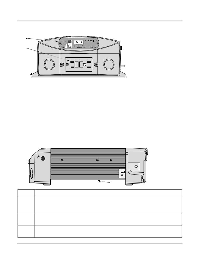
Front Panel
1
2
3
TEST
4
TEST
RESET
 RESET
RESET
XM 1000 shown
Feature |
Description |
|
|
1 |
Detachable remote panel to display inverter status and battery status information. For |
|
more information about the remote panel, see “Front Panel Operation” on page 4–2. |
|
|
2 |
GFCI receptacles provide 1000 W (XM 1000) or 1800 W (XM 1800) of power to operate |
|
AC devices. The GFCI receptacles can be removed to access the AC wiring compartment |
|
for hardwiring the inverter to an existing AC power system. |
|
|
3 |
Knockouts for routing AC input and output wiring in hardwired installations. |
|
|
4 |
Mounting flange allows you to mount the inverter permanently. |
|
|
Side View
1 
 2
2
|
3 |
Feature |
Description |
1 |
15 A supplementary circuit breaker provides overload protection for the GFCI |
|
receptacles. In a hardwired installation, the supplementary circuit breaker does not protect |
|
output wiring. |
2 |
Grounding stud connects to vehicle chassis, DC grounding bus or to engine’s negative |
|
bus. |
3 |
Cooling fans (XM 1800 only) turn on when powering loads above 500 W, or when the |
|
internal temperature rises above 113 °F (45 °C). |
2–2 |
975-0263-01-01 |
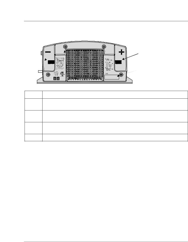
Rear Panel
Rear Panel
2 |
|
1 |
3 |
|
4 |
|
XM 1000 shown |
Feature |
Description |
1 |
Negative DC cabling terminal connects to the cable connected to the negative terminal of |
|
the battery. |
2 |
Ventilation opening must not be obstructed for the proper operation of the cooling fan and |
|
inverter. When the inverter is mounted, the ventilation opening must not point up or down. |
3 |
Positive DC cabling terminal connects to the cable connected to the positive terminal of |
|
the battery. |
4 |
Serial number of your unit. |
975-0263-01-01 |
2–3 |

2–4

3 Installation
Chapter 3 provides information on cables and fuses to help you plan for your installation, and provides procedures for installing the XM 1800.
Xantrex strongly recommends that you read the entire chapter before starting to install the XM 1800, so that you can plan an installation that is suited to your power needs.
Designing Your Installation
Before doing anything else, you need to determine how you are going to use your XM 1800, and then design a power system that will give you maximum performance. The more thorough your planning, the better your power needs will be met. In particular, you will need to:
•Be aware of installation codes
•Calculate your battery requirements
•Choose an effective charging system
•Choose an appropriate location
•Calculate the DC and AC cable sizes
•Select the correct fuses or circuit breakers.
Study Figure 3-1, “DC Input Configuration for Normal Loads” on page 3–2 and Figure 3-2, “DC Input Configuration for Heavy Loads” on page 3–3 for an examples of a setup for normal or heavy loads in a vehicle.
When you have decided upon your configuration, then you can calculate battery requirements.
3–1
Installation
|
DISCONNECT |
|
|
|
|
SWITCH |
|
|
|
GROUND TO VEHICLE CHASSIS |
ON |
|
|
|
|
|
|
||
|
|
OFF |
|
|
|
|
FUSE OR |
|
TO VEHICLE |
|
|
CIRCUIT |
|
|
|
|
BREAKER |
|
|
|
|
DEEP-CYCLE |
|
VEHICLE |
|
|
|
STARTING |
|
|
|
AUXILIARY |
|
BATTERY |
|
|
BATTERY |
|
|
|
|
|
GROUND TO |
GROUND TO |
|
|
|
VEHICLE |
|
|
|
|
VEHICLE |
|
|
|
|
CHASSIS |
|
|
FUSE OR |
|
CHASSIS |
|
|
|
|
||
TO DC LOADS |
|
|
|
|
CIRCUIT |
|
|
|
|
|
BREAKER |
DEEP-CYCLE |
|
|
|
|
AUXILIARY |
|
|
|
|
BATTERY |
|
|
|
|
|
ISOLATOR |
|
|
|
|
|
FROM ALTERNATOR |
|
|
|
|
CHARGER |
Figure 3-1 DC Input Configuration for Normal Loads
3–2 |
975-0263-01-01 |

Designing Your Installation
TO VEHICLE
FROM ALTERNATOR
CHARGER
GROUND TO
VEHICLE VEHICLE CHASSIS
STARTING
BATTERY
BATTERY ISOLATOR
|
|
FUSE OR |
|
FUSE OR |
|
|
|
|
CIRCUIT |
|
CIRCUIT |
|
|
ALL |
1 |
BREAKER |
DEEP-CYCLE |
BREAKER |
DEEP-CYCLE |
|
|
|
|
BATTERY |
|
|
BATTERY |
OFF |
2 |
|
|
|
|
|
|
|
|
|
|
|
|
|
|
BATTERY SELECTOR |
|
|
|
GROUND TO |
|
|
SWITCH |
|
|
|
VEHICLE CHASSIS |
TO DC LOADS |
|
|
|
|
|
|
|
|
|
DEEP-CYCLE |
|
|
DEEP-CYCLE |
|
|
|
BATTERY |
|
|
BATTERY |
|
|
|
FUSE OR |
|
|
FUSE OR |
|
|
|
CIRCUIT |
|
|
CIRCUIT |
|
|
|
BREAKER |
|
|
BREAKER |
|
|
|
|
ALL |
1 |
DISCONNECT/ |
|
|
|
|
|
|
|
|
|
|
|
|
|
BATTERY SELECTOR |
|
|
|
|
OFF |
2 |
SWITCH |
GROUND TO VEHICLE CHASSIS
Figure 3-2 DC Input Configuration for Heavy Loads
975-0263-01-01 |
3–3 |
Installation
Installation Codes
Governing installation codes vary depending on the location and type of installation. Electrical installations must meet local and national wiring codes and should be performed by a qualified electrician.
In residential applications, electrical codes do not allow permanent connection of AC distribution wiring to the inverter’s AC output receptacles. The receptacles are intended for temporary (as-needed) connection of cord connected loads only.
Calculating Battery Requirements
Battery type and battery size strongly affect the performance of the XM 1800. Therefore, you need to identify the type of loads your inverter will be powering, and how much you will be using them between charges.
Once you know how much power you will be using, you can determine how much battery capacity you need. Xantrex recommends that you purchase as much battery capacity as possible.
Consult Appendix B, “Battery Types” for a detailed explanation of how to determine the appropriate number and size of batteries for your needs.
CAUTION
The XM 1800 must only be connected to a 12 volt battery system. It will not operate if connected to a 6 volt battery, and will be damaged if connected to a battery of 16 volts or more.
Choosing an Effective Charging System
The charging system must be appropriate for your particular installation. A well-designed charging system will ensure that power is available when you need it and that your batteries remain in top condition. Inadequate charging will degrade system performance, and the wrong type of charger will reduce battery life.
Consult Appendix C, “Alternators and Charging Systems” for information about choosing an effective charging system.
3–4 |
975-0263-01-01 |
Designing Your Installation
Choosing an Appropriate Location
WARNING: Explosion or fire hazard
The XM 1800 contains components that may produce arcs or sparks. To prevent fire or explosion, do not install the inverter in compartments containing batteries or flammable materials, or in locations that require Ignition-Protected equipment such as areas containing gasoline engines, tanks, or fuel-line fittings.
WARNING: Fire hazard
To reduce the risk of fire, do not cover or obstruct the ventilation openings. Do not install the XM 1800 in a zero-clearance compartment. Overheating may result.
The XM 1800 must only be installed in a location that is:
:
Dry |
Do not allow water or other liquids to drip or splash on it. |
Cool |
Ambient air temperature should be between 32 ºF and |
|
105 ºF (0 ºC and 40 ºC)—the cooler the better within this |
|
range. |
Ventilated |
Allow at least 3 inches (7.5 cm) of clearance around the |
|
inverter for air flow. Ensure that the ventilation openings on |
|
the DC end of the unit are not obstructed. |
Safe |
Do not install the inverter in the same compartment as |
|
batteries or in any compartment capable of storing |
|
flammable liquids like gasoline. |
Close to |
Do not use excessive DC cable lengths. DC cable wire |
battery |
resistance and the resulting voltage drop reduces input |
|
power. Voltage drop in AC wires is of less critical |
|
importance because resistance in wire carrying AC current |
|
is less. AC wires are also less expensive. In general, longer |
|
AC wires are preferable to longer DC cables. |
Protected from |
Do not mount the inverter where it will be exposed to gases |
battery gases |
produced by batteries. Battery gases are corrosive, and |
|
prolonged exposure to battery gases will damage the |
|
inverter. |
975-0263-01-01 |
3–5 |
Installation
Calculating Cable Sizes
To operate safely and effectively, the XM 1800 needs proper cables and fuses. Because the XM 1800 has low-voltage and high-current input, it is essential that you use low-resistance wiring between the battery and the inverter to deliver the maximum amount of usable energy to your load.
For safe and efficient operation, you will need to calculate cable sizes for your:
•DC input cables from the battery to inverter (one way)
•Chassis ground cable from the grounding point to the chassis ground screw on the inverter’s DC panel.
See Figure 3-3 on page 3–12.
WARNING: Fire hazard
Never use a DC cable longer than 5 feet (1.5 meters). A cable longer than 5 feet (1.5 meters) can potentially generate enough heat to start a fire or result in poor inverter performance.
Calculating Size of DC Input Cables
Refer to Table 3-1 to plan the DC input cabling for your application:
•Use only cable rated for 90 °C
•Oil-resistant cable is recommended
•Keep all cables as short as possible, and ensure that each cable between the inverter and the battery is no longer than 5 feet (1.5 m)
•Do not use aluminum cable. It has about 1/3 more resistance than copper cable of the same size, and it is difficult to make good, lowresistance connections to aluminum wire.
3–6 |
975-0263-01-01 |
 Loading...