


TM
TM
Owner’s Guide
System Control
Panel

 TM
TM
TM
System Control Panel
Owner’s Guide
About Xantrex
Xantrex Technology Inc. (www.xantrex.com), a subsidiary of Schneider Electric, is a world leader in the development, manufacturing and marketing of advanced power electronic products and systems for the renewable and mobile power markets. The company's products convert and control raw electrical power from any central, distributed, renewable, or backup power source into high-quality power required by electronic equipment and the electricity grid. Xantrex is headquartered in Vancouver, Canada, with facilities in the United States, Germany, Spain, India, and a joint venture in China.
Trademarks
Xantrex, Smart choice for power, and Xanbus are trademarks of Schneider Electric International Services sprl, registered in the U.S. and other countries. Other trademarks, registered trademarks, and product names are the property of their respective owners and are used herein for identification purposes only.
Notice of Copyright
System Control Panel Owner’s Guide © February 2010 Xantrex Technology Inc. All rights reserved. No part of this document may be reproduced in any form or disclosed to third parties without the express written consent of: Xantrex Technology Inc., 161-G South Vasco Road, Livermore, California, USA 94551. Xantrex Technology Inc. reserves the right to revise this document and to periodically make changes to the content hereof without obligation or organization of such revisions or changes unless required to do so by prior arrangement.
Exclusion for Documentation
UNLESS SPECIFICALLY AGREED TO IN WRITING, XANTREX TECHNOLOGY INC. (“XANTREX”)
(A) MAKES NO WARRANTY AS TO THE ACCURACY, SUFFICIENCY OR SUITABILITY OF ANY TECHNICAL OR OTHER INFORMATION PROVIDED IN ITS MANUALS OR OTHER DOCUMENTATION;
(B) ASSUMES NO RESPONSIBILITY OR LIABILITY FOR LOSSES, DAMAGES, COSTS OR EXPENSES, WHETHER SPECIAL, DIRECT, INDIRECT, CONSEQUENTIAL OR INCIDENTAL, WHICH MIGHT ARISE OUT OF THE USE OF SUCH INFORMATION. THE USE OF ANY SUCH INFORMATION WILL BE ENTIRELY AT THE USER’S RISK; AND
(C) REMINDS YOU THAT IF THIS GUIDE IS IN ANY LANGUAGE OTHER THAN ENGLISH, ALTHOUGH STEPS HAVE BEEN TAKEN TO MAINTAIN THE ACCURACY OF THE TRANSLATION, THE ACCURACY CANNOT BE GUARANTEED. APPROVED XANTREX CONTENT IS CONTAINED WITH THE ENGLISH LANGUAGE VERSION WHICH IS POSTED AT WWW.XANTREX.COM.
Date and Revision |
Part Number |
February 2010 Revision D |
975-0083-01-01 |
Product Number |
|
809-0910 |
|
Contact Information
Telephone: 1 800 670 0707 (toll free North America) 1 408 987 6030 (direct)
Fax: |
1 800 994 7828 (toll free North America) |
Email: |
customerservice@xantrex.com |
Web: |
www.xantrex.com |

About This Guide
Purpose
The purpose of this Owner’s Guide is to provide explanations and procedures for installing, operating, maintaining, and troubleshooting the System Control Panel.
Scope
The Guide provides safety guidelines, setup information, and procedures for installing and configuring the System Control Panel. This Guide also includes information about operating and troubleshooting the unit. This Guide does not contain guidelines for configuring every Xanbus-enabled device that the System Control Panel monitors and controls. See the owner’s guide or operation guide for each Xanbus-enabled device for detailed configuration information.
Firmware Revision
The information in this manual applies to firmware revision 2.01.00. Some System Control Panel features and functions described in this manual may be incompatible with earlier firmware revisions. To view the firmware revision number of your product, see “Viewing device information” on page 4–11.
Audience
The Guide is intended for anyone who needs to install and/or operate the System Control Panel. Installers should be certified technicians or electricians.
Organization
This Guide is organized into six chapters and one appendix.
Chapter 1, “Introduction”, introduces and describes features of the Xantrex System Control Panel.
iii

About This Guide
Chapter 2, “Installation”, contains information and procedures for installing the System Control Panel.
Chapter 3, “System Configuration”, contains general information for using the System Control Panel to configure another device on the Xanbus system.
Chapter 4, “Configuration”, contains information and procedures for configuring the System Control Panel.
Chapter 5, “Operation”, contains information and procedures for operating the System Control Panel.
Chapter 6, “Troubleshooting”, contains reference tables of warning and fault messages.
Appendix A, “Specifications”, contains the electrical, mechanical, and environmental specifications for the System Control Panel.
Conventions Used
The following conventions are used in this guide.
WARNING
Warnings identify conditions or practices that could result in personal injury or loss of life
CAUTION
Cautions identify conditions or practices that could result in damage to the unit or other equipment.
Important: These notes contain information that is important for you to know, but is not as critical as a caution or warning.
Related Information
For more information about related products, refer to:
Xanbus System Installation Guide (975-0136-01-01) Automatic Generator Start Owner’s Guide (975-0082-01-01)
You can find more information about Xantrex Technology Inc. as well as its products and services at www.xantrex.com.
iv |
975-0083-01-01 |
Important Safety Instructions
WARNING: Save these instructions
This Owner’s Guide contains important safety and operating instructions. Before using your System Control Panel, be sure to read, understand, and save these safety instructions.
WARNING: Restrictions on use
The System Control Panel shall not be used in connection with life support systems or other medical equipment or devices.
General Precautions
1.Before installing and using this device, read all appropriate sections of this guide and any cautionary markings on the System Control Panel and the devices to which it connects.
2.If the System Control Panel has been damaged, see “Warranty and Return Information” on page WA–1.
3.Do not dismantle the System Control Panel; it contains no user serviceable parts. See “Information About Your System” on page WA–4 for instructions on obtaining service.
4.Protect the System Control Panel from rain, snow, spray, and water.
Explosive Gas Precautions
WARNING: Explosion hazard
This equipment is not ignition protected. To prevent fire or explosion, do not install the System Control Panel in compartments containing flammable materials or in locations that require ignition-protected equipment. This includes any space containing gasoline-powered machinery, fuel tanks, as well as joints, fittings, or other connections between components of the fuel system.
v

Safety
FCC Information to the User
This equipment has been tested and found to comply with the limits for a Class B digital device, pursuant to part 15 of the FCC Rules. These limits are designed to provide reasonable protection against harmful interference when the equipment is operated in a residential environment. This equipment generates, uses and can radiate radio frequency energy and, if not installed and used in accordance with the instruction guide, may cause harmful interference to radio communications. However, there is no guarantee that interference will not occur in a particular installation. If this equipment does cause harmful interference to radio or television reception, which can be determined by turning the equipment off and on, the user is encouraged to try to correct the interference by one or more of the following measures:
•Reorient or relocate the receiving antenna.
•Increase the separation between the equipment and the receiver.
•Connect the equipment into an outlet on a circuit different from that to which the receiver is connected.
•Consult the dealer or an experienced radio/TV technician for help.
vi |
975-0083-01-01 |

Contents
Important Safety Instructions - - - - - - - - - - - - - - - - - - - - - - - - - - - - - - - - - - -v
1 Introduction
About the System Control Panel - - - - - - - - - - - - - - - - - - - - - - - - - - - - - - - - - - - - 1–2 Operational Features - - - - - - - - - - - - - - - - - - - - - - - - - - - - - - - - - - - - - - - - - - - - 1–3 Physical Features - - - - - - - - - - - - - - - - - - - - - - - - - - - - - - - - - - - - - - - - - - - - - - 1–3 Front panel features - - - - - - - - - - - - - - - - - - - - - - - - - - - - - - - - - - - - - - - - - 1–3 Back panel features - - - - - - - - - - - - - - - - - - - - - - - - - - - - - - - - - - - - - - - - - 1–5 System components - - - - - - - - - - - - - - - - - - - - - - - - - - - - - - - - - - - - - - - - - - - - 1–6
2 Installation
Installing the System Control Panel - - - - - - - - - - - - - - - - - - - - - - - - - - - - - - - - - - 2–2
3 System Configuration
Configuring the System - - - - - - - - - - - - - - - - - - - - - - - - - - - - - - - - - - - - - - - - - - 3–2 Using System Control Panel buttons - - - - - - - - - - - - - - - - - - - - - - - - - - - - - - 3–2 Menu map - - - - - - - - - - - - - - - - - - - - - - - - - - - - - - - - - - - - - - - - - - - - - - - - 3–3 Changing settings for a device - - - - - - - - - - - - - - - - - - - - - - - - - - - - - - - - - - 3–4 Viewing the Select Device menu - - - - - - - - - - - - - - - - - - - - - - - - - - - - - - 3–4 Selecting the device from the Select Device menu - - - - - - - - - - - - - - - - - - 3–5 Selecting and adjusting the changeable setting - - - - - - - - - - - - - - - - - - - - - 3–5
4 Configuration
Configuring the System Control Panel - - - - - - - - - - - - - - - - - - - - - - - - - - - - - - - - 4–2
The System Panel Menu - - - - - - - - - - - - - - - - - - - - - - - - - - - - - - - - - - - - - - - - - 4–2
Basic Menu Configuration Items - - - - - - - - - - - - - - - - - - - - - - - - - - - - - - - - - - - - 4–4
Advanced Menu Configuration Items- - - - - - - - - - - - - - - - - - - - - - - - - - - - - - - - - 4–5
Using the Clock Menu- - - - - - - - - - - - - - - - - - - - - - - - - - - - - - - - - - - - - - - - - - - 4–6
Clock Menu Configuration Items - - - - - - - - - - - - - - - - - - - - - - - - - - - - - - - - - - - 4–7
Setting the time - - - - - - - - - - - - - - - - - - - - - - - - - - - - - - - - - - - - - - - - - - - - 4–7
Setting the date - - - - - - - - - - - - - - - - - - - - - - - - - - - - - - - - - - - - - - - - - - - - 4–8
975-0083-01-01 |
vii |

Contents
Using the System Settings Menu- - - - - - - - - - - - - - - - - - - - - - - - - - - - - - - - - - - |
- 4–9 |
System Settings Menu Configuration Items - - - - - - - - - - - - - - - - - - - - - - - - - - - |
4–10 |
Changing the system mode - - - - - - - - - - - - - - - - - - - - - - - - - - - - - - - - - - - |
4–10 |
Viewing device information - - - - - - - - - - - - - - - - - - - - - - - - - - - - - - - - - - |
4–11 |
5 Operation
Reading Screens and Menus- - - - - - - - - - - - - - - - - - - - - - - - - - - - - - - - - - - - - - |
- 5–2 |
System screen - - - - - - - - - - - - - - - - - - - - - - - - - - - - - - - - - - - - - - - - - - - - |
- 5–2 |
Select Device menu - - - - - - - - - - - - - - - - - - - - - - - - - - - - - - - - - - - - - - - - - |
5–3 |
Device menu - - - - - - - - - - - - - - - - - - - - - - - - - - - - - - - - - - - - - - - - - - - - - - |
5–4 |
Viewing Advanced Menus- - - - - - - - - - - - - - - - - - - - - - - - - - - - - - - - - - - - - - - - |
5–5 |
Displaying advanced menus for all devices - - - - - - - - - - - - - - - - - - - - - - - - - |
5–5 |
Combining basic and advanced menus - - - - - - - - - - - - - - - - - - - - - - - - - - - - |
5–6 |
Startup Behavior - - - - - - - - - - - - - - - - - - - - - - - - - - - - - - - - - - - - - - - - - - - - - - |
5–7 |
System Modes - - - - - - - - - - - - - - - - - - - - - - - - - - - - - - - - - - - - - - - - - - - - - - - - |
5–7 |
Changing system modes - - - - - - - - - - - - - - - - - - - - - - - - - - - - - - - - - - - - - - |
5–7 |
Operating mode - - - - - - - - - - - - - - - - - - - - - - - - - - - - - - - - - - - - - - - - - - - - |
5–7 |
Safe mode - - - - - - - - - - - - - - - - - - - - - - - - - - - - - - - - - - - - - - - - - - - - - - - - |
5–7 |
Warnings and Faults - - - - - - - - - - - - - - - - - - - - - - - - - - - - - - - - - - - - - - - - - - - - |
5–8 |
Warning messages - - - - - - - - - - - - - - - - - - - - - - - - - - - - - - - - - - - - - - - - - - |
5–8 |
Acknowledging warning messages - - - - - - - - - - - - - - - - - - - - - - - - - - - - |
5–9 |
Clearing warning messages - - - - - - - - - - - - - - - - - - - - - - - - - - - - - - - - - |
5–9 |
Viewing multiple warning messages - - - - - - - - - - - - - - - - - - - - - - - - - - - |
5–9 |
Viewing the System Control Panel warning log - - - - - - - - - - - - - - - - - - - |
5–10 |
Viewing individual warning messages from the warning log - - - - - - - - - - |
5–11 |
Fault messages - - - - - - - - - - - - - - - - - - - - - - - - - - - - - - - - - - - - - - - - - - - |
5–11 |
Viewing the System Control Panel fault log - - - - - - - - - - - - - - - - - - - - - |
5–12 |
Viewing individual fault messages from the fault log - - - - - - - - - - - - - - - |
5–13 |
Viewing multiple fault messages - - - - - - - - - - - - - - - - - - - - - - - - - - - - |
5–13 |
6 Troubleshooting
Troubleshooting Reference - - - - - - - - - - - - - - - - - - - - - - - - - - - - - - - - - - - - - - - 6–2
Types of Faults and Warnings - - - - - - - - - - - - - - - - - - - - - - - - - - - - - - - - - - 6–2
Warning Reference Table - - - - - - - - - - - - - - - - - - - - - - - - - - - - - - - - - - - - - 6–2
Fault Reference Table - - - - - - - - - - - - - - - - - - - - - - - - - - - - - - - - - - - - - - - - 6–4
viii |
975-0083-01-01 |
Contents
A Specifications
Electrical Specifications- - - - - - - - - - - - - - - - - - - - - - - - - - - - - - - - - - - - - - - - - A–2
Mechanical Specifications - - - - - - - - - - - - - - - - - - - - - - - - - - - - - - - - - - - - - - - A–2
Environmental Specifications - - - - - - - - - - - - - - - - - - - - - - - - - - - - - - - - - - - - - A–2
Warranty and Return Information - - - - - - - - - - - - - - - - - - - - - - - - - - - WA–1
Index - - - - - - - - - - - - - - - - - - - - - - - - - - - - - - - - - - - - - - - - - - - - - - - - - - - - - - - IX–1
975-0083-01-01 |
ix |
x
1 Introduction
Chapter 1 introduces and describes features of the
Xantrex System Control Panel, including the:
•Display screen
•Indicator lights
•Push Buttons
•Connector jacks
•Time-keeping, warning, and power-saving features

Introduction
About the System Control Panel
Complete |
The Xantrex System Control Panel provides configuration and |
system control |
monitoring capability for a Xanbus system. The System Control Panel: |
|
• Monitors activity throughout your power system. |
|
• Displays the settings and status of each Xanbus-enabled device. |
|
• Enables you to adjust settings for each Xanbus-enabled device. |
System |
The System Control Panel uses Xanbus™, a network communications |
component |
protocol developed by Xantrex, to communicate its settings and activity |
|
to other Xanbus-enabled devices. |
|
Xanbus-enabled products are: |
|
• Easy to use. The Xanbus network simplifies operation and automates |
|
routine tasks. |
|
• Reliable. Software control eliminates errors due to analog signaling. |
|
• Accurate. Digital information is less susceptible to interference and |
|
line loss. |
|
• Upgradable. Software upgrades mean your purchase will remain up to |
|
date. |
|
|
|
Important: The System Control Panel is compatible with Xanbus-enabled |
|
devices including RS, MS, TS and IS Series, and Freedom SW 3000 inverter/ |
|
chargers as well as the Xantrex Automatic Generator Start. The System Control |
|
Panel is not compatible with Prosine, Freedom SW 2000, Freedom HW, and |
|
Freedom HF, RV, or SW Series inverter/chargers from Xantrex. |
System |
The System Control Panel requires a Xanbus power supply to operate. |
requirements |
Network power is carried by the network cables, and can be supplied by a |
|
Xanbus-enabled product (such as an inverter/charger) or an external |
|
Xanbus power supply. |
|
As a device that draws network power, the System Control Panel |
|
consumes a maximum of 3 watts. |
|
For detailed instructions and a complete list of Xanbus-enabled devices, |
|
visit the website at www.xantrex.com. |
1–2 |
975-0083-01-01 |
Operational Features
Operational Features
Other features of the System Control Panel include:
•Time and date—has an internal clock that keeps time for the entire system.
•Audible alarm—if enabled, alerts you to a low battery condition in the system and notifies you when a fault condition arises.
•Low power consumption—automatically turns off the backlight and displays a screensaver after a period of inactivity to minimize battery drain.
•Non-volatile memory—preserves all its settings if network power is interrupted or network communication is disrupted.
Physical Features
The System Control Panel has important features on the front and back of the unit. Features on the front of the System Control Panel are the display, indicator lights, and buttons for selecting device menus and changing settings (see Figure 1-1). The back of the unit features the inputs where the System Control Panel connects to the Xanbus system (see Figure 1-2).
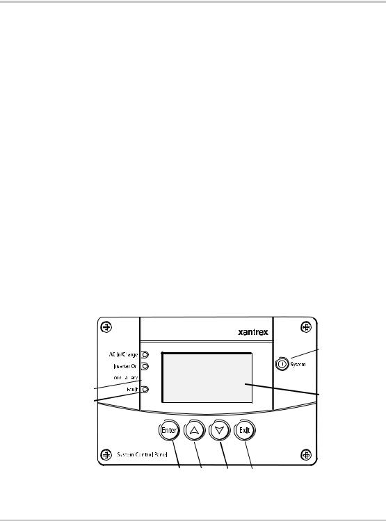
Front panel features
 9
9
1

2


3 |
10 |
|
4 |
||
|
5 6 7 8
Figure 1-1 System Control Panel front panel
975-0083-01-01 |
1–3 |

Introduction
Feature Description
1AC In/Charge light (green) indicates qualified AC is present at the input of an inverter/ charger or charger.
2Inverter On light (green) indicates an inverter is using energy from batteries to provide AC to your appliances.
3Low Battery light (yellow) indicates that a low battery voltage condition exists in the system.
4Fault light (red) indicates a device on the network is experiencing a fault and requires user attention and intervention.
5Enter button
1.Confirms selection of a menu item
2.Displays the next screen
6Up arrow button
1.Scrolls up one line of text
2.Increases a selected value
7Down arrow button
1.Scrolls down one line of text
2.Decreases a selected value
8Exit button
1.Cancels selection of a menu item
2.Displays the previous screen
9System button puts all devices in the system into Safe mode (see page 5–7).
• Hold for five seconds to activate Safe mode.
• Press momentarily to clear active faults.
10 Screen shows menus, settings, and system information.
1–4 |
975-0083-01-01 |
Physical Features
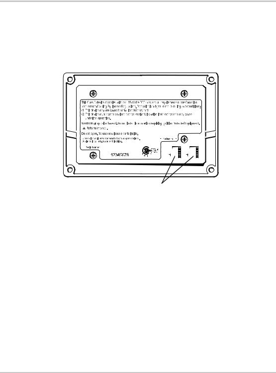
Back panel features
Connectors |
Two network connector inputs on the back panel let you connect the |
|||||||||||||||||||||||||||||||||||||||||||||||||||||||||||||||||
|
System Control Panel to other Xanbus-enabled devices. See Figure 1-2. |
|||||||||||||||||||||||||||||||||||||||||||||||||||||||||||||||||
|
|
|
|
|
|
|
|
|
|
|
|
|
|
|
|
|
|
|
|
|
|
|
|
|
|
|
|
|
|
|
|
|
|
|
|
|
|
|
|
|
|
|
|
|
|
|
|
|
|
|
|
|
|
|
|
|
|
|
|
|
|
|
|
|
|
|
|
|
|
|
|
|
|
|
|
|
|
|
|
|
|
|
|
|
|
|
|
|
|
|
|
|
|
|
|
|
|
|
|
|
|
|
|
|
|
|
|
|
|
|
|
|
|
|
|
|
|
|
|
|
|
|
|
|
|
|
|
|
|
|
|
|
|
|
|
|
|
|
|
|
|
|
|
|
|
|
|
|
|
|
|
|
|
|
|
|
|
|
|
|
|
|
|
|
|
|
|
|
|
|
|
|
|
|
|
|
|
|
|
|
|
|
|
|
|
|
|
|
|
|
|
|
|
|
|
|
|
|
|
|
|
|
|
|
|
|
|
|
|
|
|
|
|
|
|
|
|
|
|
|
|
|
|
|
|
|
|
|
|
|
|
|
|
|
|
|
|
|
|
|
|
|
|
|
|
|
|
|
|
|
|
|
|
|
|
|
|
|
|
|
|
|
|
|
|
|
|
|
|
|
|
|
|
|
|
|
|
|
|
|
|
|
|
|
|
|
|
|
|
|
|
|
|
|
|
|
|
|
|
|
|
|
|
|
|
|
|
|
|
|
|
|
|
|
|
|
|
|
|
|
|
|
|
|
|
|
|
|
|
|
|
|
|
|
|
|
|
|
|
|
|
|
|
|
|
|
|
|
|
|
|
|
|
|
|
|
|
|
|
|
|
|
|
|
|
|
|
|
|
|
|
|
|
|
|
|
|
|
|
|
|
|
|
|
|
|
|
|
|
|
|
|
|
|
|
|
|
|
|
|
|
|
|
|
|
|
|
|
|
|
|
|
|
|
|
|
|
|
|
|
|
|
|
|
|
|
|
|
|
|
|
|
|
|
|
|
|
|
|
|
|
|
|
|
|
|
|
|
|
|
|
|
|
|
|
|
|
|
|
|
|
|
|
|
|
|
|
|
|
|
|
|
|
|
|
|
|
|
|
|
|
|
|
|
|
|
|
|
|
|
|
|
|
|
|
|
|
|
|
|
|
|
|
|
|
|
|
|
|
|
|
|
|
|
|
|
|
|
|
|
|
|
|
|
|
|
|
|
|
|
|
|
|
|
|
|
|
|
|
|
|
|
|
|
|
|
|
|
|
|
|
|
|
|
|
|
|
|
|
|
|
|
|
|
|
|
|
|
|
|
|
|
|
|
|
|
|
|
|
|
|
|
|
|
|
|
|
|
|
|
|
|
|
|
|
|
|
|
|
|
|
|
|
|
|
|
|
|
|
|
|
|
|
|
|
|
|
|
|
|
|
|
|
|
|
|
|
|
|
|
|
|
|
|
|
|
|
|
|
|
|
|
|
|
|
|
|
|
|
|
|
|
|
|
|
|
|
|
|
|
|
|
|
|
|
|
|
|
|
|
|
|
|
|
|
|
|
|
|
|
|
|
|
|
|
|
|
|
|
|
|
|
|
|
|
|
|
|
|
|
|
|
|
|
|
|
|
|
|
|
|
|
|
|
|
|
|
|
|
|
|
|
|
|
|
|
|
|
|
|
|
|
|
|
|
|
|
|
|
|
|
|
|
|
|
|
|
|
|
|
|
|
|
|
|
|
|
|
|
|
|
|
|
|
|
|
|
|
|
|
|
|
|
|
|
|
|
|
|
|
|
|
|
|
|
|
|
|
|
|
|
|
|
|
|
|
|
|
|
|
|
|
|
|
|
|
|
|
|
|
|
|
|
|
|
|
|
|
|
|
|
|
|
|
|
|
|
|
|
|
|
|
|
|
|
|
|
|
|
|
|
|
|
|
|
|
|
|
|
|
|
|
|
|
|
|
|
|
|
|
|
|
|
|
|
|
|
|
|
|
|
|
|
|
|
|
|
|
|
|
|
|
|
|
|
|
|
|
|
|
|
|
|
|
|
|
|
|
|
|
|
|
|
|
|
|
|
|
|
|
|
|
|
|
|
|
|
|
|
|
|
|
|
|
|
|
|
|
|
|
|
|
|
|
|
|
|
|
|
|
|
|
|
|
|
|
|
|
|
|
|
|
|
|
|
|
|
|
|
|
|
|
|
|
|
|
|
|
|
|
|
|
|
|
|
|
|
|
|
|
|
|
|
|
|
|
|
|
|
|
|
|
|
|
|
|
|
|
|
|
|
|
|
|
|
|
|
|
|
|
|
|
|
|
|
|
|
|
|
|
|
|
|
|
|
|
|
|
|
|
|
|
|
|
|
|
|
|
|
|
|
|
|
|
|
|
|
|
|
|
|
|
|
|
|
|
|
|
|
|
|
|
|
|
|
|
|
|
|
|
|
|
|
|
|
|
|
|
|
|
|
|
|
|
|
|
|
|
|
|
|
|
|
|
|
|
|
|
|
|
|
|
|
|
|
|
|
|
|
|
|
|
|
|
|
|
|
|
|
|
|
|
|
|
|
|
|
|
|
|
|
|
|
|
|
|
|
|
|
|
|
|
|
|
|
|
|
|
|
|
|
|
|
|
|
|
|
|
|
|
|
|
|
|
|
|
|
|
|
|
|
|
|
|
|
|
|
|
|
|
|
|
|
|
|
|
|
|
|
|
|
|
|
|
|
|
|
|
|
|
|
|
|
|
|
|
|
|
|
|
|
|
|
|
|
|
|
|
|
|
|
|
|
|
|
|
|
|
|
|
|
|
|
|
|
|
|
|
|
|
|
|
|
|
|
|
|
|
|
|
|
|
|
|
|
|
|
|
|
|
|
|
|
|
|
|
|
|
|
|
|
|
Network connectors (8-pin RJ45)
Figure 1-2 System Control Panel rear panel
975-0083-01-01 |
1–5 |
Introduction
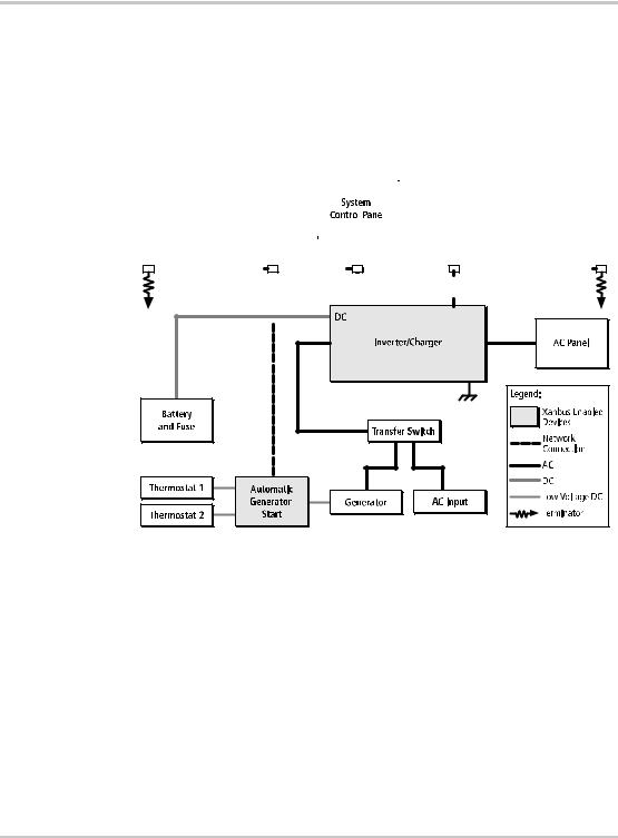
System components
System |
The Xanbus system includes the System Control Panel and other Xanbus- |
|||||||||||||||||||||||||||||||||||||||||||||||||||||||||||||||||||||||||||||||||||||||
description |
enabled devices. Each device interacts and communicates with the other |
|||||||||||||||||||||||||||||||||||||||||||||||||||||||||||||||||||||||||||||||||||||||
|
devices. |
|||||||||||||||||||||||||||||||||||||||||||||||||||||||||||||||||||||||||||||||||||||||
Network |
In Figure 1-3, network connections are represented by dotted lines and |
|||||||||||||||||||||||||||||||||||||||||||||||||||||||||||||||||||||||||||||||||||||||
diagram |
conventional electrical connections are represented by solid lines. |
|||||||||||||||||||||||||||||||||||||||||||||||||||||||||||||||||||||||||||||||||||||||
|
|
|
|
|
|
|
|
|
|
|
|
|
|
|
|
|
|
|
|
|
|
|
|
|
|
|
|
|
|
|
|
|
|
|
|
|
|
|
|
|
|
|
|
|
|
|
|
|
|
|
|
|
|
|
|
|
|
|
|
|
|
|
|
|
|
|
|
|
|
|
|
|
|
|
|
|
|
|
|
|
|
|
|
|
|
|
|
|
|
|
|
|
|
|
|
|
|
|
|
|
|
|
|
|
|
|
|
|
|
|
|
|
|
|
|
|
|
|
|
|
|
|
|
|
|
|
|
|
|
|
|
|
|
|
|
|
|
|
|
|
|
|
|
|
|
|
|
|
|
|
|
|
|
|
|
|
|
|
|
|
|
|
|
|
|
|
|
|
|
|
|
|
|
|
|
|
|
|
|
|
|
|
|
|
|
|
|
|
|
|
|
|
|
|
|
|
|
|
|
|
|
|
|
|
|
|
|
|
|
|
|
|
|
|
|
|
|
|
|
|
|
|
|
|
|
|
|
|
|
|
|
|
|
|
|
|
|
|
|
|
|
|
|
|
|
|
|
|
|
|
|
|
|
|
|
|
|
|
|
|
|
|
|
|
|
|
|
|
|
|
|
|
|
|
|
|
|
|
|
|
|
|
|
|
|
|
|
|
|
|
|
|
|
|
|
|
|
|
|
|
|
|
|
|
|
|
|
|
|
|
|
|
|
|
|
|
|
|
|
|
|
|
|
|
|
|
|
|
|
|
|
|
|
|
|
|
|
|
|
|
|
|
|
|
|
|
|
|
|
|
|
|
|
|
|
|
|
|
|
|
|
|
|
|
|
|
|
|
|
|
|
|
|
|
|
|
|
|
|
|
|
|
|
|
|
|
|
|
|
|
|
|
|
|
|
|
|
|
|
|
|
|
|
|
|
|
|
|
|
|
|
|
|
|
|
|
|
|
|
|
|
|
|
|
|
|
|
|
|
|
|
|
|
|
|
|
|
|
|
|
|
|
|
|
|
|
|
|
|
|
|
|
|
|
|
|
|
|
|
|
|
|
|
|
|
|
|
|
|
|
|
|
|
|
|
|
|
|
|
|
|
|
|
|
|
|
|
|
|
|
|
|
|
|
|
|
|
|
|
|
|
|
|
|
|
|
|
|
|
|
|
|
|
|
|
|
|
|
|
|
|
|
|
|
|
|
|
|
|
|
|
|
|
|
|
|
|
|
|
|
|
|
|
|
|
|
|
|
|
|
|
|
|
|
|
|
|
|
|
|
|
|
|
|
|
|
|
|
|
|
|
|
|
|
|
|
|
|
|
|
|
|
|
|
|
|
|
|
|
|
|
|
|
|
|
|
|
|
|
|
|
|
|
|
|
|
|
|
|
|
|
|
|
|
|
|
|
|
|
|
|
|
|
|
|
|
|
|
|
|
|
|
|
|
|
|
|
|
|
|
|
|
|
|
|
|
|
|
|
|
|
|
|
|
|
|
|
|
|
|
|
|
|
|
|
|
|
|
|
|
|
|
|
|
|
|
|
|
|
|
|
|
|
|
|
|
|
|
|
|
|
|
|
|
|
|
|
|
|
|
|
|
|
|
|
|
|
|
|
|
|
|
|
|
|
|
|
|
|
|
|
|
|
|
|
|
|
|
|
|
|
|
|
|
|
|
|
|
|
|
|
|
|
|
|
|
|
|
|
|
|
|
|
|
|
|
|
|
|
|
|
|
|
|
|
|
|
|
|
|
|
|
|
|
|
|
|
|
|
|
|
|
|
|
|
|
|
|
|
|
|
|
|
|
|
|
|
|
|
|
|
|
|
|
|
|
|
|
|
|
|
|
|
|
|
|
|
|
|
|
|
|
|
|
|
|
|
|
|
|
|
|
|
|
|
|
|
|
|
|
|
|
|
|
|
|
|
|
|
|
|
|
|
|
|
|
|
|
|
|
|
|
|
|
|
|
|
|
|
|
|
|
|
|
|
|
|
|
|
|
|
|
|
|
|
|
|
|
|
|
|
|
|
|
|
|
|
|
|
|
|
|
|
|
|
|
|
|
|
|
|
|
|
|
|
|
|
|
|
|
|
|
|
|
|
|
|
|
|
|
|
|
|
|
|
|
|
|
|
|
|
|
|
|
|
|
|
|
|
|
|
|
|
|
|
|
|
|
|
|
|
|
|
|
|
|
|
|
|
|
|
|
|
|
|
|
|
|
|
|
|
|
|
|
|
|
|
|
|
|
|
|
|
|
|
|
|
|
|
|
|
|
|
|
|
|
|
|
|
|
|
|
|
|
|
|
|
|
|
|
|
|
|
|
|
|
|
|
|
|
|
|
|
|
|
|
|
|
|
|
|
|
|
|
|
|
|
|
|
|
|
|
|
|
|
|
|
|
|
|
|
|
|
|
|
|
|
|
|
|
|
|
|
|
|
|
|
|
|
|
|
|
|
|
|
|
|
|
|
|
|
|
|
|
|
|
|
|
|
|
|
|
|
|
|
|
|
|
|
|
|
|
|
|
|
|
|
|
|
|
|
|
|
|
|
|
|
|
|
|
|
|
|
|
|
|
|
|
|
|
|
|
|
|
|
|
|
|
|
|
|
|
|
|
|
|
|
|
|
|
|
|
|
|
|
|
|
|
|
|
|
|
|
|
|
|
|
|
|
|
|
|
|
|
|
|
|
|
|
|
|
|
|
|
|
|
|
|
|
|
|
|
|
|
|
|
|
|
|
|
|
|
|
|
|
|
|
|
|
|
|
|
|
|
|
|
|
|
|
|
|
|
|
|
|
|
|
|
|
|
|
|
|
|
|
|
|
|
|
|
|
|
|
|
|
|
|
|
|
|
|
|
|
|
|
|
|
|
|
|
|
|
|
|
|
|
|
|
|
|
|
|
|
|
|
|
|
|
|
|
|
|
|
|
|
|
|
|
|
|
|
|
|
|
|
|
|
|
|
|
|
|
|
|
|
|
|
|
|
|
|
|
|
|
|
|
|
|
|
|
|
|
|
|
|
|
|
|
|
|
|
|
|
|
|
|
|
|
|
|
|
|
|
|
|
|
|
|
|
|
|
|
|
|
|
|
|
|
|
|
|
|
|
|
|
|
|
|
|
|
|
|
|
|
|
|
|
|
|
|
|
|
|
|
|
|
|
|
|
|
|
|
|
|
|
|
|
|
|
|
|
|
|
|
|
|
|
|
|
|
|
|
|
|
|
|
|
|
|
|
|
|
|
|
|
|
|
|
|
|
|
|
|
|
|
|
|
|
|
|
|
|
|
|
|
|
|
|
|
|
|
|
|
|
|
|
|
|
|
|
|
|
|
|
|
|
|
|
|
|
|
|
|
|
|
|
|
|
|
|
|
|
|
|
|
|
|
|
|
|
|
|
|
|
|
|
|
|
|
|
|
|
|
|
|
|
|
|
|
|
|
|
|
|
|
|
|
|
|
|
|
|
|
|
|
|
|
|
|
|
|
|
|
|
|
|
|
|
|
|
|
|
|
|
|
|
|
|
|
|
|
|
|
|
|
|
|
|
|
|
|
|
|
|
|
|
|
|
|
|
|
|
|
|
|
|
|
|
|
|
|
|
|
|
|
|
|
|
|
|
|
AC In
AC Out
Figure 1-3 Network diagram
1–6 |
975-0083-01-01 |
2 Installation
Chapter 2 contains information and procedures for planning and performing a System Control Panel installation, including:
•Materials and tools required
•Choosing a location
•Mounting the unit
•Connecting the System Control Panel to other devices
Installation
Installing the System Control Panel
|
The System Control Panel is designed to be flush mounted through an |
|
opening in a wall and secured with four #6 screws. Use the supplied |
|
mounting template to precisely mark the opening and screw hole |
|
locations. |
Planning an |
The System Control Panel requires no connections other than the network |
installation |
cables that plug into the back of the unit. Because you cannot access the |
|
network inputs once the unit is mounted, the network cables need to be |
|
routed through the wall before securing the System Control Panel. |
Materials and tools required
Choosing a location
CAUTION
Allow at least 2 ¼ inches (57 mm) of space behind the wall to accommodate the depth of the unit and allow room for the network cables to bend.
Refer to the Xanbus System Installation Guide for more information about planning and installing a network that includes the System Control Panel.
You will need these materials and tools to complete the installation:
mounting template sticker (supplied)
four #6 screws (supplied)
Phillips head screwdriver
jigsaw or small keyhole saw
power drill with 1/8" bit (optional)
Xantrex network cables or equivalent
Choose a location that is easily accessible. The System Control Panel should be mounted where it is easily visible, with unobstructed access to the screen and push buttons.
The location should be indoors, dry, and free from corrosive or explosive fumes.
2–2 |
975-0083-01-01 |
Installing the System Control Panel
WARNING: Fire hazard
The System Control Panel is not ignition protected. Do not install in areas requiring ignition-protected equipment.
WARNING: Shock hazard
Before making an opening in a wall, bulkhead, or panel, ensure there is no wiring or other obstruction within the wall.
To mount the System Control Panel:
1.Peel the backing from the supplied mounting template sticker and place it in your chosen installation location. Use the template to mark locations for the mounting holes and the area to be cut out.
2.Pilot-drill the mounting holes (if necessary, depending on your mounting surface) and, using a jigsaw, cut out the hole in which the System Control Panel will be inserted.
3.Route the network cable(s) from other Xanbus-enabled devices inside the wall and through the opening.
CAUTION: Equipment damage
Connect the System Control Panel only to other Xanbus compatible devices.
:
Although the cabling and connectors used in this network system are the same as Ethernet connectors, this network is not an Ethernet system. Equipment damage may result from attempting to connect these two different systems.
4.Connect the network cable(s) (and terminator if necessary) to either input on the back of the System Control Panel. See Figure 2-1.
Connect one network cable and a network terminator to the System Control Panel if it is the last device at the end of a daisy chain-type network layout. Refer to the Xanbus System Installation Guide for more information.
5.Place the unit in the opening and secure it with four #6 screws.
6.Peel off the protective plastic coating covering the screen and indicator lights.
975-0083-01-01 |
2–3 |
 Loading...