

Xantrex
Sun Tie XR
STXR1500
STXR2500
Installation and Operation Guide

Sun Tie XR
Installation and Operation Guide

About Xantrex
Xantrex Technology Inc. is a world-leading supplier of advanced power electronics and controls with products from
50 watt mobile units to one MW utility-scale systems for wind, solar, batteries, fuel cells, microturbines, and backup
power applications in both grid-connected and stand-alone systems. Xantrex products include inverters, battery
chargers, programmable power supplies, and variable speed drives that convert, supply, control, clean, and distribute
electrical power.
Trademarks
Xantrex is a registered trademark of Xantrex International.
Other trademarks, registered trademarks, and product names are the property of their respective owners and are used
herein for identification purposes only.
Notice of Copyright
Sun Tie XR Installation and Operation Guide © February 2003 Xantrex International. All rights reserved.
Disclaimer
UNLESS SPECIFICALLY AGREED TO IN WRITING, XANTREX TECHNOLOGY INC. (“XANTREX”)
(a) MAKES NO WARRANTY AS TO THE ACCURACY, SUFFICIENCY OR SUITABILITY OF ANY
TECHNICAL OR OTHER INFORMATION PROVIDED IN ITS MANUALS OR OTHER DOCUMENTATION.
(b) ASSUMES NO RESPONSIBILITY OR LIABILITY FOR LOSS OR DAMAGE, WHETHER DIRECT,
INDIRECT, CONSEQUENTIAL OR INCIDENTAL, WHICH MIGHT ARISE OUT OF THE USE OF SUCH
INFORMATION. THE USE OF ANY SUCH INFORMATION WILL BE ENTIRELY AT THE USER’S RISK.
Date and Revision
February 2003, Revision 1
Part Number
975-0053-01-01
Contact Information
Telephone: 360.435.8826
Fax: 360.925.5143
Email: CustomerService@xantrex.com
Web: www.xantrex.com

About This Guide
Purpose
The Sun Tie XR Installation and Operation Guide contains information for a qualified
installer and authorized service person to install, operate and troubleshoot the Xantrex
Sun Tie XR.
Scope
The guide provides safety guidelines, installation, operation, troubleshooting, and
warranty information for the Sun Tie XR.
The guide does not provide detailed information about solar (photovoltaic or “PV”)
arrays or requirements for connecting to the utility power grid. You will need to
consult the PV array manufacturer’s guide and your local electrical utility for this
information.
About This Guide
Organization
This guide is organized into four chapters and two appendixes:
Chapter 1, “Introduction”, outlines the main performance and safety
features of the Sun Tie XR. Reading this chapter will give you a clear
understanding of the inverter’s capabilities.
Chapter 2, “Installation”, provides information about planning for and
performing a Sun Tie XR installation.
Chapter 3, “Operation”, provides procedures for starting up the inverter
and operating the unit. It explains how to read the front panel display to
monitor the Sun Tie XR’s operation.
Chapter 4, “Troubleshooting”, for authorized service personnel only,
explains how to identify and solve problems that can occur with the
Sun Tie XR.
Appendix A, “Specifications”, provides the electrical, mechanical and
physical specifications of the Sun Tie XR.
Appendix B, “Warranty and Product Information”, contains the product’s
warranty. The appendix also explains how to return a product for service,
and to prepare for a call to Xantrex Customer Service.
Conventions Used
To reduce the risk of electrical shock and to ensure the safe installation
and operation of this product, the following safety symbols have been
placed throughout this manual to indicate dangerous conditions and
important safety instructions.
WARNING
Warnings identify conditions that could result in personal
injury or loss of life.
CAUTION
Cautions identify conditions or practices that could result in
damage to the Sun Tie XR or to other equipment.
ii 975-0053-01-01

Note: Notes describe additional information which may add to your
understanding of how to install or use the Sun Tie XR.
Related Information
You can find more information about Xantrex Technology Inc. and its
products and services at www.xantrex.com
About This Guide
975-0053-01-01 iii
iv 975-0053-01-01


Contents
1
Introduction
About the Sun Tie XR- - - - - - - - - - - - - - - - - - - - - - - - - - - - - - - - - - - - - - - - - - - - - - 1–2
Standard Features - - - - - - - - - - - - - - - - - - - - - - - - - - - - - - - - - - - - - - - - - - - - - -1–3
Accessories - - - - - - - - - - - - - - - - - - - - - - - - - - - - - - - - - - - - - - - - - - - - - - - - - - -1–3
2
Installation
Installation Planning - - - - - - - - - - - - - - - - - - - - - - - - - - - - - - - - - - - - - - - - - - - - - - - 2–2
Overview - - - - - - - - - - - - - - - - - - - - - - - - - - - - - - - - - - - - - - - - - - - - - - - - - - - -2–2
Tools required - - - - - - - - - - - - - - - - - - - - - - - - - - - - - - - - - - - - - - - - - - - - - -2–2
Hardware and materials required - - - - - - - - - - - - - - - - - - - - - - - - - - - - - - - - -2–2
Locating the Sun Tie XR - - - - - - - - - - - - - - - - - - - - - - - - - - - - - - - - - - - - - - -2–3
Routing the wires - - - - - - - - - - - - - - - - - - - - - - - - - - - - - - - - - - - - - - - - - - - -2–3
Planning AC Connections - - - - - - - - - - - - - - - - - - - - - - - - - - - - - - - - - - - - - - - - -2–4
Recommended wire sizes - - - - - - - - - - - - - - - - - - - - - - - - - - - - - - - - - - - - - -2–4
AC circuit breaker requirements - - - - - - - - - - - - - - - - - - - - - - - - - - - - - - - - - -2–5
Planning DC Connections - - - - - - - - - - - - - - - - - - - - - - - - - - - - - - - - - - - - - - - - -2–5
Grounding Requirements - - - - - - - - - - - - - - - - - - - - - - - - - - - - - - - - - - - - - - - - -2–6
PV Array Requirements - - - - - - - - - - - - - - - - - - - - - - - - - - - - - - - - - - - - - - - - - -2–7
Installation - - - - - - - - - - - - - - - - - - - - - - - - - - - - - - - - - - - - - - - - - - - - - - - - - - - - - 2–9
Overview - - - - - - - - - - - - - - - - - - - - - - - - - - - - - - - - - - - - - - - - - - - - - - - - - - - -2–9
Mounting - - - - - - - - - - - - - - - - - - - - - - - - - - - - - - - - - - - - - - - - - - - - - - - - - - - -2–9
Connecting DC Wiring - - - - - - - - - - - - - - - - - - - - - - - - - - - - - - - - - - - - - - - - - - 2–15
Connecting AC Wiring - - - - - - - - - - - - - - - - - - - - - - - - - - - - - - - - - - - - - - - - - - 2–16
Grounding the System - - - - - - - - - - - - - - - - - - - - - - - - - - - - - - - - - - - - - - - - - -2–18
Connecting Inverters in Parallel - - - - - - - - - - - - - - - - - - - - - - - - - - - - - - - - - - - - 2–21
Installing the Optional Remote Monitor - - - - - - - - - - - - - - - - - - - - - - - - - - - - - - 2–22
3
Operation
Startup Procedure- - - - - - - - - - - - - - - - - - - - - - - - - - - - - - - - - - - - - - - - - - - - - - - - - 3–2
Required Equipment - - - - - - - - - - - - - - - - - - - - - - - - - - - - - - - - - - - - - - - - - - - -3–2
Checking the PV Array DC Voltage - - - - - - - - - - - - - - - - - - - - - - - - - - - - - - - - - -3–2
Checking the AC Utility Voltage - - - - - - - - - - - - - - - - - - - - - - - - - - - - - - - - - - - -3–3
Starting up the Sun Tie XR - - - - - - - - - - - - - - - - - - - - - - - - - - - - - - - - - - - - - - - -3–4
Monitoring the Front Panel Display - - - - - - - - - - - - - - - - - - - - - - - - - - - - - - - - - -3–5
Reading the Front Panel Display - - - - - - - - - - - - - - - - - - - - - - - - - - - - - - - - - - - -3–6
Status Indicator Lights - - - - - - - - - - - - - - - - - - - - - - - - - - - - - - - - - - - - - - - - - - -3–7
Reassembling the Sun Tie XR - - - - - - - - - - - - - - - - - - - - - - - - - - - - - - - - - - - - - -3–8

Contents
Factors Affecting Sun Tie XR Performance- - - - - - - - - - - - - - - - - - - - - - - - - - - - - - - 3–10
PV Array Factors - - - - - - - - - - - - - - - - - - - - - - - - - - - - - - - - - - - - - - - - - - - - - 3–10
Other Factors - - - - - - - - - - - - - - - - - - - - - - - - - - - - - - - - - - - - - - - - - - - - - - - - 3–11
4
Troubleshooting
Troubleshooting the Sun Tie XR - - - - - - - - - - - - - - - - - - - - - - - - - - - - - - - - - - - - - - - 4–2
Viewing the Status LEDs - - - - - - - - - - - - - - - - - - - - - - - - - - - - - - - - - - - - - - - - - 4–2
Troubleshooting Reference Table - - - - - - - - - - - - - - - - - - - - - - - - - - - - - - - - - - - - - - 4–5
A
Specifications
Electrical Specifications - - - - - - - - - - - - - - - - - - - - - - - - - - - - - - - - - - - - - - - - - - - - A–2
Mechanical Specifications - - - - - - - - - - - - - - - - - - - - - - - - - - - - - - - - - - - - - - - - - - A–3
Standard Features and Options - - - - - - - - - - - - - - - - - - - - - - - - - - - - - - - - - - - - - - - A–4
Efficiency Curve - - - - - - - - - - - - - - - - - - - - - - - - - - - - - - - - - - - - - - - - - - - - - - - - - A–5
Temperature Derating Curve- - - - - - - - - - - - - - - - - - - - - - - - - - - - - - - - - - - - - - - - - A–6
B
Warranty and Product Information
Limited Warranty - - - - - - - - - - - - - - - - - - - - - - - - - - - - - - - - - - - - - - - - - - - - - - - - B–2
Return Material Authorization Policy - - - - - - - - - - - - - - - - - - - - - - - - - - - - - - - - - - - B–5
Return Procedure - - - - - - - - - - - - - - - - - - - - - - - - - - - - - - - - - - - - - - - - - - - - - - - - B–5
Information About Your System - - - - - - - - - - - - - - - - - - - - - - - - - - - - - - - - - - - - - - B–6
vi 975-0053-01-01
Important Safety Instructions
WARNING: SAVE THESE INSTRUCTIONS
This manual contains important safety instructions that should
be followed during the installation and maintenance of this
product. Specific safety instructions for installation, operation,
and troubleshooting are in their respective sections. Read and
keep this manual for future reference.
DANGER: SHOCK HAZARD
Do not remove the upper cover. Removing the upper cover should
be performed only by authorized service personnel. If you suspect
your unit is not functioning correctly, call Xantrex.
For safe installation and operation:
• All electrical work must be done in accordance with local and national electrical
codes.
• Before installing or using this device, read all instructions and cautionary markings
located in the manual, on the Sun Tie XR and on the PV array.

Important Safety Instructions
• Do not expose this unit to rain, snow or liquids of any type without
• To reduce the chance of short circuits when installing or working with
• Remove all jewelry such as rings, bracelets, wristwatches and
• The Sun Tie XR contains more than one live circuit (the PV array and
• This product contains no user-serviceable parts. Return the unit to
• Wiring to the utility should only be done after receiving prior
• Completely cover the surface of all PV arrays with an opaque (dark)
the Rain Shield installed. The Rain Shield does not, however, make
the Sun Tie XR waterproof.
the inverter or the PV array, use insulated tools.
necklaces prior to installing this system. This will greatly reduce the
chance of accidental exposure to live circuits.
the AC line). Power may be present at more than one source even
when the circuit breakers are off.
Xantrex for maintenance.
approval from the utility company and performed only by a qualified
electrician.
material before wiring them. PV arrays produce electrical energy
when exposed to light and could create a hazardous condition.
viii 975-0053-01-01

Introduction
Chapter 1, “Introduction”, describes the standard features and
accessories for the Sun Tie XR.
Introduction
About the Sun Tie XR
The Xantrex Sun Tie XR grid-connect solar inverter is designed to
convert a home or business into a “green” power generating station. The
Sun Tie XR converts solar electric (photovoltaic, or PV) power into
utility-grade electricity that can be used by the home or sold to the power
company. Installing the Sun Tie XR consists of mounting it to the wall
and connecting a DC source (a PV array) and the AC output to the utility.
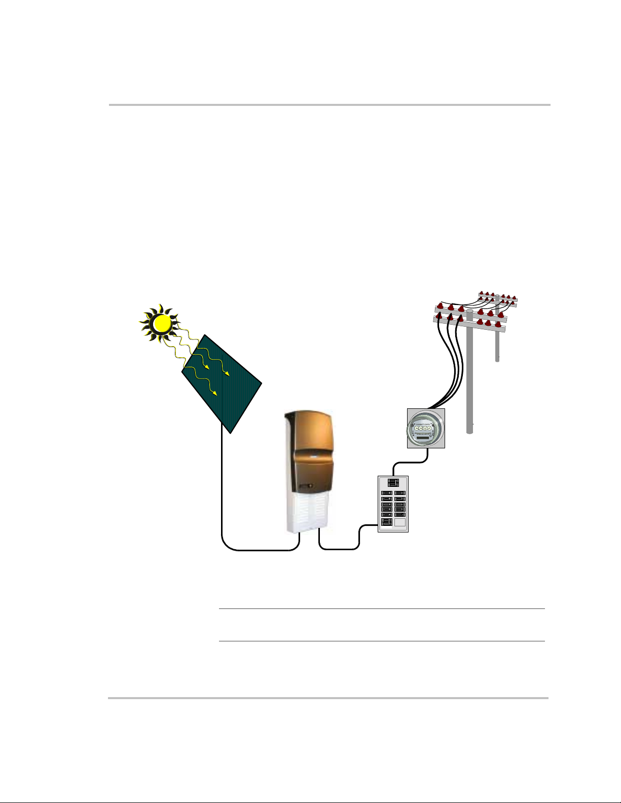
See Figure 1-1 for a simple diagram of a typical installation. In order to
operate, the Sun Tie XR must have grid power available and connected. It
will not provide backup power.
Solar-harvested
AC power to grid
PV array
Figure 1-1
DC input voltage
Basic System Overview
Note:
Figure 1-1 is a one-line drawing intended as a system overview
only. System grounding and other electrical details are not included.
Sun Tie XR
AC output
voltage
OFF
OFF
OFF
OFF
OFF
OFF
OFF
Sun Tie
OFF
ON
OFF
ON
ON
ON
OFF
OFF
ON
ON
OFF
ON
ON
OFF
ON
ON
ON
ON
OFF
ON
ON
AC utility meter
Main utility
electrical panel
1–2 975-0053-01-01

About the Sun Tie XR
Standard Features
All-in-one design All necessary DC input and AC output connections, disconnects and
circuit breakers are housed within the Sun Tie XR’s easily installed,
compact enclosure. A built-in LCD display panel provides easy-to-read
system status and daily cumulative energy production information. Two
status LEDs inside the unit also provide operating and troubleshooting
information.
Uses most types of
PV technology
The Sun Tie XR is designed to take advantage of most types of solar
electric technologies. The inverter allows up to 120 VDC open circuit PV
modules to be used, so it will work with both crystalline and thin film PV
modules.
Sun Sweep™
Maximum Power
Point Tracking
(MPPT)
Sun Sweep
technology that allows the Sun Tie XR to harvest the maximum amount
of energy from your solar array. No matter what PV system you choose—
single crystalline, polycrystalline or thin film—SunSweep
TM
is Xantrex’s proprietary Maximum Power Point Tracking
TM
learns your
array’s specific characteristics, maximizing its output all day, all season,
year after year.
High efficiency The high-frequency, solid-state design of the Sun Tie XR inverter is
extremely efficient. Above 500 watts, the inversion process is 90%
efficient (or greater) with a peak efficiency of 91%.
Expandable Sun Tie XR inverters may be connected in a parallel configuration for
increasing net metering capacity. The modular expandability of the
Sun Tie XR Series allows for system growth.
Meets standards and
requirements
The Sun Tie XR has complete on-board islanding protection and meets
U.S. and Canadian safety operating standards and code requirements.
Accessories
• STRM–Sun Tie XR Remote Monitor, for remote display of system
status, energy production, troubleshooting log, and resetting Wh.
• STRS–Sun Tie XR Rain Shield, required for outdoor installation.
975-0053-01-01 1–3
1–4 975-0053-01-01


Installation
Chapter 2, “Installation” provides information about planning for
and installing the Sun Tie XR. It contains information to help you
plan wire routes, AC and DC connections, and find a suitable
location for installation. It also discusses requirements for
grounding the Sun Tie XR and your PV array.
This chapter then provides procedures to install the Sun Tie XR,
including mounting, making DC and AC connections, and
grounding the inverter and the PV array.

Installation
Installation Planning
Overview
Before you begin to install the Sun Tie XR you need to consider the
following:
• tools required
• hardware and materials required
• mounting location
• routes for AC and DC wiring
• AC and DC connection wire size requirements
• grounding requirements
• PV array requirements
Tools required
❐ Phillips screwdrivers ❐ level
❐ slot-head screwdrivers ❐ wire strippers
❐ open-end wrenches ❐ torque wrench
❐ socket wrench and fittings ❐ electrical tape
❐ 3/32" hex bit
❐ multimeter ❐ utility knife
❐ frequency counter (optional)
❐ pencil
Hardware and materials required
❐ wood screws and washers (supplied)
❐ metal conduit and appropriate fittings
❐ anchors for screws (material dependent)
2–2 975-0053-01-01
Locating the Sun Tie XR
The Sun Tie XR should be installed in locations that meet the following
requirements:
Installation Planning
Vertical The UL listing for the Sun Tie XR requires it
to be mounted vertically.
Dry When the Sun Tie is mounted outdoors, attach
the optional Rain Shield (STRS) to prevent
water entering the unit.
Temperature The unit meets specifications from 32 to
113 °F (0 to 45 °C) but will operate within the
temperature extremes of most climates—from
-38 to 113 °F (-39 to 45 °C). At extreme cold
temperatures the LCD display may not
function normally and it is recommended that
an indoor-mounted Remote Monitor be used.
At temperatures above 45 °C, the unit begins
derating power. See “Temperature Derating
Curve” on page A–6.
Ground clearance The Sun Tie requires at least 36 inches (100
cm) of clearance between the bottom of the
unit and the ground.
Dust free Dust can be drawn inside and accumulate
within the unit, interfering with wiring
connections and ventilation.
WARNING: SHOCK HAZARD
Do not install the Sun Tie XR unit outdoors without the Rain
Shield. Water entering the unit could cause a dangerous
condition and cause the unit to fail. Failure due to improper
installation will void the warranty.
Routing the wires
Typical
configurations
975-0053-01-01 2–3
Determine all wire routes to and from the Sun Tie XR. Typical routing
configurations include:
• AC wiring from the Sun Tie XR to the main service panel
• DC input wiring from the PV array to the Sun Tie XR
• DC ground from the PV array to an external ground rod
Installation
All wiring and installation methods should conform to applicable
electrical and building codes.
Conduit holes Pre-plan the wire and conduit runs. Knockouts for conduit holes are
located on the bottom of the unit. See Figure 2-9.
Acceptable wire
sizes
The DC terminal blocks in the Sun Tie XR accept up to a #6 AWG wire.
The AC circuit disconnects accept cable sizes up to #6 AWG.
For maximum safety, run AC and DC wires/cables in separate conduits.
WARNING: SHOCK HAZARD
Check for existing electrical or plumbing prior to drilling holes
in the walls.
Planning AC Connections
AC connections include all the wires and connectors between the
Sun Tie XR AC output breakers and the main utility electrical panel.
Figure 2-14 and Figure 2-15 show simplified diagrams of the entire
installation.
Recommended wire sizes
The AC output breakers accept wire sizes from #6–14 AWG. Refer to
Table 2-1 for minimum recommended wire size. The values in Table 2-1
are the minimum recommended wire sizes in conduit. Installing a large
number of wires in conduit or enclosed locations may require larger wire
sizes. Consult your local/national electrical code for more information.
Table 2-1 Recommended minimum AC wire sizes
Minimum wire size for specified distance
AC amps
Inverter model
STXR1500 6.3 7.9 14 AWG 10 AWG 8 AWG
STXR2500 10.4 13.0 12 AWG 8 AWG 6 AWG
output per leg
Note:
NEC amps per leg
(amps x 125%)
The six-circuit combiner board is rated for 100 amps (Imp) of
0–50 ft
one way
maximum real current. Although the 20 amp fuses will theoretically
allow 120 amps to be applied, always design for a maximum of 100
amps maximum current. With appropriate fuse deratings, per NEC code,
the maximum allowed current is 16 amps for any of the six circuits.
50–100 ft
one way
100–200 ft
one way
2–4 975-0053-01-01
Installation Planning
AC circuit breaker requirements
The main service panel must dedicate a 15 amp minimum, double pole
breaker (120/240 volts AC) to operate the Sun Tie XR.
Planning DC Connections
DC connections include all the wires and connectors between your PV
array and the Sun Tie XR’s combiner board. Figure 2-1 and Figure 2-2
show the combiner board and connection points. Figure 2-14 and Figure
2-15 show simplified diagrams of the entire installation.
Wire Sizes The DC connections are made on the combiner board inside the
Sun Tie XR. The combiner board accepts wire sizes from #6–14 AWG.
Refer to Table 2-2 for minimum recommended wire sizes.
Exceptions The values in Table 2-2 are the minimum recommended wire sizes.
Installing a large number of wires in conduit or enclosed locations may
require larger wire sizes. Consult your local or national electrical code for
more information.
NEC Restrictions The National Electrical Code (NEC) places restrictions on minimum DC
wire bending radius. A #6 AWG wire is the largest that may be used on
the Sun Tie XR when connecting to the individual fused circuits of the
combiner board.
Table 2-2 Recommended minimum DC wire sizes
Minimum wire size for specified distance
DC amps (Imp)
(from PV array)
1.0 1.6 14 AWG 14 AWG 14 AWG
3.0 4.7 14 AWG 12 AWG 10 AWG
5.0 7.8 12 AWG 10 AW G 6 AWG
7.0 10.9 12 AWG 8 AWG 6 AWG
9.0 14.0 10 AWG 8 AWG Not Recommended
11.0 17.2 10 AWG 6 AWG Not Recommended
NEC amps
(amps x 156%)
Note:
For an installation requiring a two-wire run (positive and
0–25 ft
one way
25–50 ft
one way
50–100 ft
one way
negative), the PV array wires can bypass the individual fused combiner
board terminals and connect directly to the input terminals (through an
externally mounted DC fused combiner box) by using the positive and
negative bypass terminals on the combiner board. Refer to Figure 2-2
and Table 2-2 for connection and wire sizes.
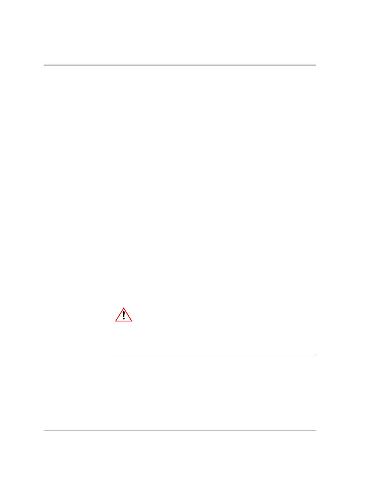
975-0053-01-01 2–5
Installation
PV Array Fuses
(F1 to F6)
Positive PV Array Fused
Terminal Connections
(1 to 6)
Negative PV Array Fused
Terminal Connections
DC conduit wiring
(from PV arrays)
Figure 2-1 Combiner board with PV array wiring to individual terminal
connections
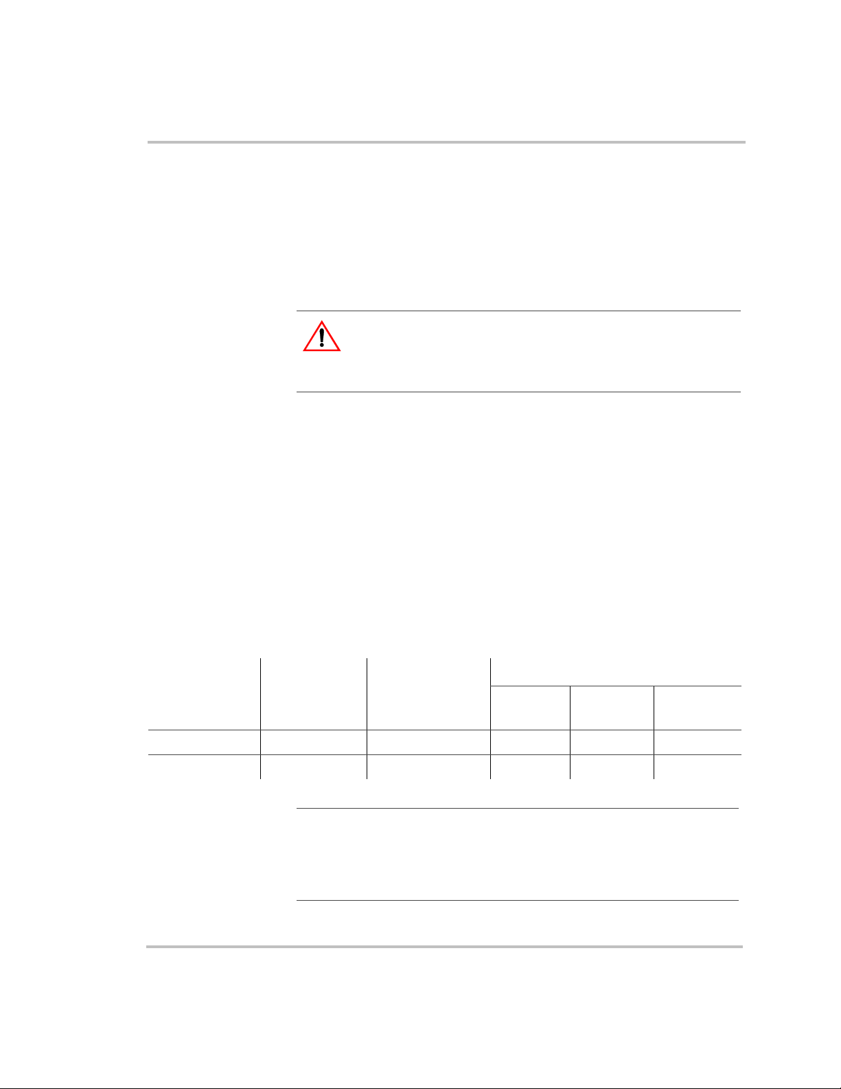
PV array wiring (two-line
run to bypass terminals—
note polarity)
pos (+)
neg (–)
Figure 2-2 Combiner board with PV array wiring to bypass terminals
Grounding Requirements
AC grounding The Sun Tie XR must be connected to a grounded, permanent wiring
system.
2–6 975-0053-01-01
Installation Planning
DC grounding The negative PV conductor must be bonded to the grounding system at
only one point in the system. See Figure 2-3 for the location of the Sun
Tie XR ground bar. The size for the conductor is usually based on the size
of the largest conductor in the DC system. Negative/ground bonding is
accomplished by factory-wired PVGFP breakers.
Figure 2-3 Ground bar location
PV Array Requirements
MPPT operational
window
Vo l t a g e
requirements
The Sun Tie XR is optimized to work with 4-each, 12 volt nominal
crystalline PV modules in series (48 VDC nominal), or various
combinations of amorphous, thin film PV modules. Ensure the PV array
used in the system operates within the maximum peak power tracking
(MPPT) operational window.
The solar array connected to the Sun Tie XR should have a minimum of
50 volts DC open-circuit in full sunlight conditions. Crystalline solar
arrays configured for 48 volts DC nominal will have an open-circuit
voltage of around 84 volts DC in full sunlight. The MPPT software
controls the output of the solar modules, under loaded conditions, in the
42–85 volts DC range (full inverter output power occurs between 52–85
VDC for the STXR1500 and between 52–75 VDC for the STXR2500).
Other array voltages will either not operate the inverter, may cause
damage, or will not allow maximum harvest of the sun’s energy.
Ground bar
(connect to solid earth ground)
975-0053-01-01 2–7

Installation
Note:
batteries.
The MPPT algorithm does not work with wind power or
CAUTION
Although the nominal voltage range suggests that you can use
strings of five modules in series, this is not safe for the unit, as
the PV array may exceed the inverter’s maximum input
(120 VDC).
WARNING: SHOCK HAZARD
Whenever a PV array is exposed to sunlight, a shock hazard
exists at the output cables or exposed terminals. To reduce the
risk of shock during installation, cover the array with an opaque
(dark) material before making any connections.
2–8 975-0053-01-01

Installation
Overview
Installation steps There are four main steps in the installation of the Sun Tie XR:
1. Mounting the unit
2. Making the DC connections from the PV array to the Sun Tie XR
3. Making the AC connections from the service utility panel to the
Sun Tie XR
4. Grounding the PV array
This section also discusses two installation options: connecting inverters
in parallel and connecting the Remote Monitor.
WARNING: FIRE, SHOCK and ENERGY HAZARDS
Before installing the Sun Tie XR, read all instructions and
cautionary markings located in this manual, on the PV array,
and on the main service panel.
Installation
Mounting
Surfaces for
mounting
The Sun Tie XR must be mounted to a flat, vertical surface such as
wallboard or wood siding. Installation onto wallboard or concrete
requires the use of anchors to properly hold the screws.
WARNING: SHOCK HAZARD
Before drilling holes to mount the Sun Tie XR, ensure there are
no electrical wires or plumbing in this area. Since this unit is
installed close to the utility entrance or meter, there may be a
high concentration of electrical wire in the area.
CAUTION
The Sun Tie XR weighs approximately 35 pounds. Always use
proper lifting techniques during installation to prevent personal
injury.
975-0053-01-01 2–9

Installation
To mount the Sun Tie XR:
1. Locate the area where the Sun Tie XR is to be installed. Installing it
as close to the utility service panel as possible is recommended. The
bottom of the unit must be at least 36 inches from the floor or ground
when mounted.
2. Using a level, place the mounting bracket up to the wall (in a
horizontal position) and mark the area for the three screws, as shown
in Figure 2-4. To achieve the 36-inch height from the bottom of the
Sun Tie XR to the ground, mount the bracket 70 inches from the
ground.
3. If required, remove the bracket and drill the holes using a #10 (0.193
diameter) drill bit. Drill appropriately sized holes for anchors when
installing on non-wood surfaces.
4. Mount the bracket to the wall using the screws and washers provided.
If mounting to a surface other than wood, use the appropriate screws
and anchors.
5. Place the Sun Tie XR’s rear lip, located on the back top of the
enclosure, over the bracket and ensure it is seated properly, as shown
in Figure 2-5.
6. Remove the lower external cover to access the internal circuit breaker
panel by removing the screw on each side of the cover with a 3/32
hex bit, as shown in Figure 2-6.
7. Remove the internal breaker panel by removing the screws in the
breakers and the breaker cover grounding screw. Lift the panel until
the lower locking tabs are free, then gently pull the inner cover
outward, as shown in Figure 2-7. Save the screws for reinstallation.
8. After the unit is correctly seated on the upper bracket, locate the two
screw holes in the bottom (back) area of the enclosure and mark these
locations on the wall, as shown in Figure 2-5 and Figure 2-8. Remove
the Sun Tie XR (if required).
9. Drill two pilot holes (as above, if required).
10. Reinstall the Sun Tie XR to the bracket and secure the bottom of the
unit with the wood screws and washers provided (or appropriate
screws and anchors for non-wood surfaces) and tighten.
"
"
Note:
supplied.
2–10 975-0053-01-01
Mounting hardware for surfaces other than wood is not

Installation
Wall bracket, screws,
and washers (supplied)
Figure 2-4 Bracket mounting
9 41/64"
4 13/16"
Enclosure
mounted on
wall bracket
19/64"
26 21/32"
Mount 70 inches (minimum) from ground
Sun Tie XR enclosure lip
onto bracket
8 55/64"
Screw
holes
3.20"
Figure 2-5 Enclosure mounting
975-0053-01-01 2–11

Installation
Upper cover
Remove screws
(one on each side)
External breaker cover
(remove during
installation)
Figure 2-6 External cover components
2–12 975-0053-01-01

Remove breaker
screws
Lift up and pull
forward to remove
Locking tabs
remove breaker cover
grounding screw
Figure 2-7 Inner breaker cover
Installation
PV combiner board
Internal mounting
holes
Figure 2-8 Mounting holes
975-0053-01-01 2–13

Installation
10
3
3
8
3
2
(2X)
1
(2X)
8
3
8
3
4
1
3
8
3
4
8
1
5
2
5
7
8
7
8
8
3
8
4
3
1
8
7
8
1
2
3
10
8
front of inverter
all dimensions are in inches
1
3
4
5
1
8
5
2
8
Figure 2-9 Bottom hole conduit locations (bottom view)
2–14 975-0053-01-01

Installation
Connecting DC Wiring
Fuse requirements The combiner board in the Sun Tie XR accepts up to six individual PV
array circuits (positive and negative wires). Each circuit on the combiner
board contains a fuse to protect against over-current. Always replace this
fuse with one of the same type and rating (GBB, 20 amp maximum,
ceramic type, 0.25" x 1.25"). The combiner board is rated for 100 amps
maximum input.
Combiner board
location
Wiring procedure Before connecting DC wiring, refer to Figure 2-10.
PV array wiring to
terminal block
(note polarity)
+
–
The combiner board PV array input connection block is located in the
lower left-hand section of the Sun Tie XR unit.
PVGFP (ganged)
100 amp DC breaker
PVGFP (ganged)
1 amp DC breaker
PV array
100 amp DC breaker
L1 15 amp AC breaker
(ganged)
L2 15 amp AC breaker
(ganged)
L2 breaker AC
connection
L1 breaker AC
connection
Ground bar
Figure 2-10 Electrical component location and PV array DC connection points
To wire the PV array to Sun Tie XR:
1. Install the DC conduit from the PV arrays to the bottom of the
Sun Tie XR, through one of the knockout holes, as shown in Figure 2-
9. Metal conduit is highly recommended.
2. Route the wires from the PV array(s) through the conduit and into the
lower section of the Sun Tie XR enclosure, as shown in Figure 2-8.
Note:
If you are using more than one PV sub-array, label the positive
and negative wire pairs appropriately (such as PV 1, PV 2, and so on).
3. Connect the positive (+) wire from the #1 array to the PV PLUS 1
terminal on the combiner board. Check that the wire is in the proper
location and tighten the screw.
975-0053-01-01 2–15

Installation
4. Connect the negative (–) wire from the PV array to the PV MINUS 1
(leftmost) terminal. Check that the wire is in the proper location and
tighten the screw.
5. Repeat this procedure for each PV array circuit, connecting the #2 PV
positive wire to the terminal labeled PV PLUS 2, and so on.
The PV arrays do not have to connect in the order marked on the
board (this is just for reference). All PV array positives on the
combiner board are joined together AFTER the fuse.
6. Repeat this procedure for each PV array circuit, connecting the #2 PV
negative wire to the PV MINUS 2 terminal, and so on.
The PV arrays do not have to connect in the order marked on the
board (this is just for reference). All PV array negatives on the
combiner board are electrically tied together.
7. Torque wires according to the following values.
Wire Size (AWG) Torque (in-lb)
14–10 AWG 35
8 AWG 40
Connecting AC Wiring
AC HOT wiring is connected to the Sun Tie XR’s L1 and L2 breakers,
and the ground wire connects to the ground bar. All AC wiring is located
in the lower section of the Sun Tie XR.
Note:
meter, or to dual meters, where one meter indicates power used and the
second meter indicates power sold (power supplied back to the utility).
The installer and utility must determine the proper components to
install.
4–6 AWG 45
2–1/0 AWG 50
WARNING: SHOCK HAZARD
AC utility wiring to the Sun Tie XR unit is performed directly
at the main breaker panel. This should be done only by a
qualified utility installer or electrician with prior utility
company approval.
The Sun Tie XR can be connected to a single bidirectional
2–16 975-0053-01-01

Installation
WARNING: SHOCK HAZARD
Before wiring the Sun Tie XR, ensure the main 120/240 volt
breaker in the main utility breaker box is switched off. Switch
this breaker on only after all wiring is completed as instructed
in the procedures.
To wire the main utility panel to the Sun Tie XR:
1. Run conduit from the main utility breaker panel to the lower section
of the Sun Tie XR. Run the two HOT wires (L1 and L2) and ground
through the conduit and into the Sun Tie XR’s lower section. Metal
conduit is highly recommended.
2. Install or use existing double-pole 15-amp circuit breaker (or two
single-pole 15-amp breakers, ganged) in the main utility breaker
panel.
3. Connect the L1 HOT wire (black) from the 15-amp, double-pole
breaker installed in the main breaker panel, to the breaker labeled L1
in the Sun Tie XR. Refer to Figure 2-11.
4. Connect the L2 HOT wire (red) from the remaining 15-amp, doublepole breaker installed in the main breaker panel, to the breaker
labeled L2 in the Sun Tie XR.
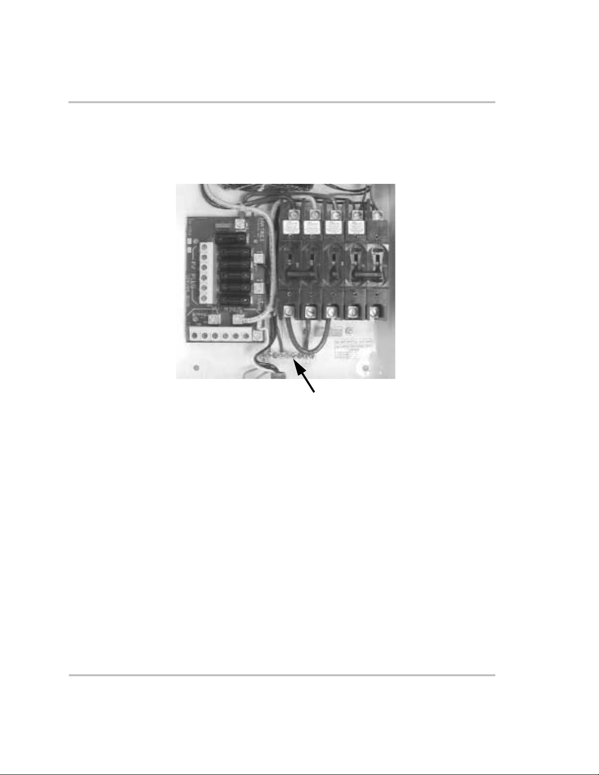
5. Connect the ground wire (green or bare copper) from the ground bar
in the main breaker panel, to the ground bar in the lower section of the
Sun Tie XR.
6. Ensure all connections are correctly wired and properly torqued.
7. Torque wires according to the following values.
Wire Size Torque (in-lb)
14–10 AWG 35
8 AWG 40
6 AWG 45
975-0053-01-01 2–17

Installation
L1
240 VAC
L2
Ground bar
Figure 2-11 240 VAC connection points
Grounding the System
PV grounding The Sun Tie XR is designed to have all PV positive, negative and ground
conductors connected inside its access area. The PV equipment ground
should be connected to the Sun Tie XR ground bar. This ground bar must
also be connected to the main utility breaker panel’s ground bar and to the
house grounding rod according to the NEC requirements. Verify that there
is an AC ground/neutral bond in the main utility breaker panel and that no
other ground/neutral bonds exist in the system.
Lightning
protection
Recommended
additional
grounding
To protect the equipment from lightning damage, use a single-point
grounding system. In this system, all ground lines terminate at the same
point. This point normally is the main utility ground installed by the
utility company to provide a ground for the house wiring. This ground
usually consists of a copper rod driven 6 to 8 feet into the earth, as shown
in Figure 2-12.
Xantrex recommends that if the inverter is more than 8 feet from the
utility ground rod, a second ground rod should be added (Reference NEC
250.56) and bonded to the same point (Reference NEC 250.58) to
minimize the impedance to ground and maximize system protection.
2–18 975-0053-01-01

Solar
Array
Connect all
array frames
together and
ground
DC Wiring
(and ground)
Sun Tie Unit
Ground
Bar
AC Wiring
Main Utility
Breaker Panel
Ground
Bar
AC
Wiring
Utility
Meter
AC
Wiring to
Utility
Installation
Array
Ground
Wire
*Optional Array Ground Wire
*
NOTE
: An optional array ground wire
may be required in many states as an
additional permanent ground p ath in
the event the inverter is removed for
service. Check your local codes for
grounding requirements.
Sun Tie
Ground
Rod
Utility
Ground
Wire
Figure 2-12 Typical roof mount installation grounding
Required additional
grounding
If the PV array is located a considerable distance (over 100 feet) from the
Sun Tie XR, then an additional ground rod must be installed close to the
PV array for the most reliable lightning protection, as shown in Figure 2-
13. The grounded frame of the PV array provides a direct route to
dissipate lightning strikes through the closest ground rod. Please
reference NEC 2002 250.53 – “Grounding Electrode System
Installations” and NEC 2002 250.70 – “Methods of Grounding and
Bonding Conductor Connections to Electrodes” for specific grounding
requirements.
Note:
Always refer to your local codes for wiring and grounding
requirements, which may differ from the information given in this
manual.
Bonded Neutral Wire
Utility
Ground
Rod
975-0053-01-01 2–19

Installation
> 100 feet (30 m)
Solar
Array
Ground
Frame to
Pole
Array Ground
Wire
DC Wiring
(and ground)
Ground
Bar
Buried Copper Wire Buried Copper Wire
Array Ground Rod Utility Gr ound Rod
Sun Tie Ground Rod
Figure 2-13 Long distance grounding
SOV
LIGHTNING
A
15 A
L1
15 A
L2
GROUND
BAR
NOTES:
INSTALLER CONNECTIONS REQUIRED
(A)
AT POINTS
INVERTER ENCLOSURE.
THE UTILITY METER MAY BE A
BI-DIRECTIONAL METER OR DUAL
METERS .
OBTAIN UTILITY COMPANY APPROVAL
BEFORE INSTALLING.
AND
ARRESTOR
(OPTION)
L1
L2
INVERTER
G
G
Main
Breakers
G
L2
L1
Sun-Tie
Breakers
MAIN SERVICE PANEL
(B)
TO THE
ST Unit
Sun Tie Ground Wire
+
–
NEUTRAL
GROUND
Main Utility
Breaker Panel
Ground
AC Wiring
Bar
STXR UNIT
PV GROUND FAULT
BREAKERS (OPTION)
100 A
100 A
+
–
1 A
L2
L1
UTILITY METER
N
Buried copper wi re if second ground rod is used
Utility
Meter
AC
Wiring
Bonded Neut ral Wire
Utility Gr ound Wire
PV COMBINER BO ARD
– +
20 A
–
20 A
–
20 A
–
20 A
–
20 A
–
20 A
–
L1
L2
N
+
+
–
+
+
–
+
+
–
+
+
–
+
+
–
+
+
B
UTILITY
GRID
AC
Wiring to
Utility
PV
ARRAYS
Extra Ground Rod
Only Required on
Long Runs > 1 00
feet (30 m).
Figure 2-14 Simplified electrical wiring diagram
2–20 975-0053-01-01

SOV
LIGHTNING
A
L1
L2
NOTES:
INSTALLER CON NECTIONS REQUIRED AT P OINTS
THE INVERTER ENCL OSURE.
THE UTILITY METER MAY BE A BI-DIRECTIO NAL METER OR DUAL
METERS MA Y BE USED.
OBTAIN UTILITY COMPAN Y APPROVAL BEFORE INSTALLING.
ARRESTOR
(OPTION)
15 A
15 A
L1
L2
G
G
Breakers
G
L2
L1
MAIN SERVICE PANEL
(A)
AND
(B)
Main
Sun-Tie
Breakers
INVERTER
TO
GROUND
NEUTRAL
STXR UNIT
+
–
BYPASS TERMINALS
PV GROUND FAULT
BREAKERS (OPTION)
100 A
+
–
1 A
L1
UTILITY METER
Installation
PV ARRAY
EXTERNAL
COMBINER BOARD
–
+
PV COMBINER BOARD
+
–
20 A
+
–
20 A
100 A
L2
N
+
–
20 A
+
–
20 A
+
–
20 A
+
–
20 A
+
–
Extra Ground Rod
B
Only Required on
Long Runs > 100
feet (30 m).
L1
UTILITY
L2
GRID
N
975-S00-003A
Figure 2-15 Simplified electrical wiring diagram (using PV bypass terminals)
Connecting Inverters in Parallel
Reasons and
requirements
Connecting AC and
DC wiring
975-0053-01-01 2–21
Sun Tie XR inverters may be connected in a parallel configuration to
harvest additional energy from the sun. In this configuration, a separate
solar array is required for each Sun Tie XR unit. The output of each Sun
Tie XR feeds a dual-pole 15-amp circuit breaker (L1 and L2) in the main
utility breaker panel.
The procedure for wiring the additional Sun Tie XR is exactly the same as
previously described for the AC and DC wiring. Additional Sun Tie XR
inverters can be added in the future as required.
An example of a parallel configuration is shown in Figure 2-16.
Note:
If you are combining two Sun Tie XR inverters into a single
dual-pole breaker (30 amp, for example), you will need to size the AC
wires and conduit to the larger breaker. If this breaker trips, it will also
shut down both inverters. For these reasons, we do not recommend
using a single dual-pole breaker.

Installation
PV ARRAY
SOV
LIGHTNING
ARRESTOR
(OPTION)
15 A
L1
15 A
L2
G
MAIN UTILITY PANEL
Main
Breakers
L2
15 A
15 A
L1
L2
15 A
15 A
L1
NEUTRAL
GROUND
15 A
L1
15 A
L2
G
House Ground
(Ground Rod)
L1
L2
N
UTILITY
GRID
L2
UTILITY METER
N
L2
L1
L1
Sun-Tie XR
Breakers
(Dual-Pole)
Sun-Tie XR
Breakers
(Dual-Pole)
Neutral/Ground
Bond
Figure 2-16 Parallel Sun Tie XR configuration
L1
L2
SOV
INVERTER
LIGHTNING
ARRESTOR
(OPTION)
L1
L2
INVERTER
SUN TIE XR #1
PV GROUND FAULT
BREAKERS (OPTION)
+
–
SUN TIE XR #2
+
–
100 A
+
–
1 A
PV GROUND FAULT
BREAKERS (OPTION)
100 A
PV COMBINER BOARD
+
–
20 A
+
–
20 A
100 A
+
–
20 A
+
–
20 A
+
–
20 A
+
–
20 A
+
–
PV ARRAY
PV COMBINER BOARD
– +
20 A
+
–
20 A
100 A
+
–
1 A
+
–
20 A
+
–
20 A
+
–
20 A
+
–
20 A
+
–
Installing the Optional Remote Monitor
Remote Monitor
function
2–22 975-0053-01-01
The optional Remote Monitor provides additional functions which are not
directly available on the front panel LCD display. It can be mounted in a
more accessible location such as the garage, kitchen, living room, and so
on. Refer to the “Sun Tie XR Series Remote Monitor Installation and
Operator’s Guide” (part number 975-0032-01-02) for installation details.

Installation
To wire the Remote Monitor to the Sun Tie XR:
1. Route the Remote Monitor’s six-conductor cable separate from the
other wiring to prevent noise and interference from being introduced
into the data cable. Refer to Figure 2-17 and Figure 2-18. The
connector is located in the upper right-hand section of the wiring
compartment.
CAUTION
When routing the Remote Monitor cable, do not use a metal
conduit. Metal conduit may induce noise in the remote cable
and cause scrambled data to appear on the display.
2. Run the cable through one of the lower knockouts (with a strain relief
installed) and plug it into the Remote Monitor port.
3. Recheck all wiring and reinstall the panels and the Rain Shield (if
used).
CAUTION
The P.C. com. port next to the Remote Monitor port is not
enabled. Connecting a computer to this port may result in
damage to the inverter or the computer.
Remote Monitor port (located
on top of wiring access
compartment)
Figure 2-17 Location of optional Remote Monitor port
975-0053-01-01 2–23

Installation
Route Remote Monitor
cable away from AC
and DC wires
Remote Monitor
connection
CPU board (cover
removed for clarity)
Figure 2-18 Remote Monitor connection and cable
2–24 975-0053-01-01

Operation
Chapter 3, “Operation” provides procedures for starting up and
operating the Sun Tie XR. It also explains the messages that appear
on the front panel display. The chapter ends with information about
factors that affect how much power the Sun Tie XR can gather from
the PV array and deliver to the utility grid.

Operation
Startup Procedure
Starting up the Sun Tie XR requires several steps. You will need to:
1. Check the PV array DC voltage.
2. Check the AC utility voltage.
3. Start up the Sun Tie by switching on the DC and AC circuit breakers
inside the unit.
4. Reassemble the Sun Tie XR and replace the external covers.
Required Equipment
You will need the following equipment to help you start up the
Sun Tie XR:
❐ AC voltmeter (or multimeter)
❐ DC voltmeter (or multimeter)
❐ Frequency counter (optional)
WARNING: SHOCK HAZARD
Hazardous voltages present from two sources. Use extreme
caution during startup procedure. Before applying power to the
Sun Tie XR, ensure all AC and DC wiring is correct.
Checking the PV Array DC Voltage
To check the PV array DC voltage:
1. Uncover the PV arrays and expose them to full sunlight. The sunlight
must be intense enough to produce the required output voltage.
2. Measure the PV array open circuit DC voltage across the DC positive
(+) and negative (–) terminals as shown in Figure 3-1. This voltage
must be greater than 50 volts DC for 5 minutes minimum to start the
inverter.
Note:
voltages from 100–120 volts. Crystalline solar modules will produce
open circuit voltages at 75–85 volts (four modules wired in series). An
open circuit voltage of 50 volts or more is required for 5 minutes to start
the inverter. The 5-minute time delay is required by safety standards.
3. Switch on the PVGFP and DC breakers.
Some thin film modules (amorphous) may produce open circuit
3–2 975-0053-01-01

> 50 VDC
Startup Procedure
AC
VOLTS
DC
VOLTS
+
Figure 3-1 PV array DC voltage test
Checking the AC Utility Voltage
Note:
applications. For commercial applications where only 208 VAC is
available, the Sun Tie XR may be installed with the appropriate use of a
buck-boost transformer.
To check the AC utility voltage:
1. Switch on the main 240 V breakers in the building’s electrical service
The Sun Tie XR is designed primarily for residential
panel.
–
2. Ensure all circuit breakers located in the Sun Tie XR unit are in the
off (down) position.
3. Using an AC voltmeter, measure the AC open circuit utility voltage
between L1 and L2, as shown in Figure 3-2. Ensure this voltage is
approximately 240 volts AC. The inverter operates with a line-to-line
voltage (L1 to L2) ranging from 211–264 volts AC.
4. Switch on the ganged 15 amp Sun Tie XR circuit breakers located in
the main electrical service panel. This applies the utility-supplied
240 volts AC to the Sun Tie XR unit.
975-0053-01-01 3–3

Operation
240 VAC
Figure 3-2 AC voltage test
Starting up the Sun Tie XR
To start up the inverter:
1. Switch on the 100-amp DC circuit breaker located in the Sun Tie XR
unit. This breaker supplies the DC power from the PV array to the
Sun Tie unit. Refer to Figure 3-3, item 1.
2. Switch on the 1 and 100 amp (ganged) PVGFP breakers. These
breakers open when 1 amp or greater is detected in the DC negativeto-ground line; indicating a ground fault condition. Refer to Figure 3-
3, item 2.
AC
VOLTS
Connect to
L2 terminal
Connect to
L1 terminal
DC
VOLTS
3. Switch on the double-pole 15 amp AC circuit breakers located in the
Sun Tie XR unit. These breakers provide the Sun Tie XR-produced
power to the utility and provide the necessary utility voltage and
frequency to the inverter. This means the inverter will not produce an
AC output if utility voltage is not present on its output. Refer to
Figure 3-3, item 3.
3–4 975-0053-01-01

Startup Procedure
2
1
3
Figure 3-3 Startup sequence
Monitoring the Front Panel Display
During startup During startup, the inverter’s front panel LCD display shows the first four
messages described in “Reading the Front Panel Display”.
During waiting
period
During operation When the five-minute wait protection timer stops, the Sun Tie XR begins
When the five-minute timer begins, the inverter displays the countdown
timer status meter.
selling power, indicated by the power output reading in the display. The
array “Wh” values will increase slowly, depending on the array size and
sunlight intensity.
Note:
The values in the front panel LCD display are calibrated at the
factory. The calibration is not user-adjustable.
975-0053-01-01 3–5

Operation
Front panel
LCD display
Figure 3-4 Front panel display location
Reading the Front Panel Display
During startup During startup, the Sun Tie XR will display several messages on its front
panel LCD display. These messages appear in the following order.
Message Display Duration
XANTREX TECH INC.
STXR2500
(or “STXR1500”)
Enhanced with
Sun Sweep
CPU Rev = x.x
LCD Rev = x.x
244 vac 74 vdc
Start in 300 sec
3–6 975-0053-01-01
8 seconds
Cycles with the Lifetime Energy and Time Online
messages for five minutes. See “After startup”.

Startup Procedure
After startup After the 300-second countdown timer and during normal operation, the
Sun Tie will display four messages that repeat every minute.
Display
Message (with
sample data)
duration
(seconds) Description
54 mppt 74 vdc
2500 W 12123 Wh*
244 vac 74 vdc
2500 W 12123 Wh*
Lifetime Energy
10.000kWh
Time Online
Today 00:00:00
0 – 8 Message 1 shows the inverter’s
DC regulation voltage for
maximum power production,
DC input voltage, power output,
and energy harvested today.
8 – 16 Message 2 shows AC input
voltage, DC input voltage, the
power output and energy
harvested today.
16 – 24 Repeats message 1.
24 – 28 Repeats message 2.
28 – 32 Message 3 shows the amount of
energy produced since
installation and startup.
32 – 40 Repeats message 1.
40 – 48 Repeats message 2.
48 – 56 Repeats message 1.
56 – 60 Message 4 shows how long the
Sun Tie has been online since it
last started.
*If the inverter is disconnected due to a line condition, this display will
show one of the following messages:
• AC NOT PRESENT
•AC MAINS LOW
• AC MAINS HIGH
• FREQUENCY FAULT
Status Indicator Lights
The Sun Tie XR is equipped with two status indicator lights (LEDs)
above the circuit breakers inside the wiring compartment. These light
during operation to indicate the inverter’s current status. For information
about reading these lights, see Chapter 4, “Troubleshooting”.
975-0053-01-01 3–7

Operation
Reassembling the Sun Tie XR
Once the Sun Tie XR is operating normally and producing power, you
need to replace the panels and covers that were removed during
installation and startup.
WARNING: SHOCK HAZARD
Before reattaching covers, remove AC power at the utility
panel and cover the PV arrays.
To reassemble the Sun Tie XR:
1. Replace the circuit breaker panel, as shown in Figure 3-5.
a) Install the circuit breaker (inner) panel by sliding it into place
under the top cover and fitting its two locking tabs into the slots
on the bottom of the Sun Tie XR.
b) Secure the front panel to the circuit breaker with the four screws.
c) Replace the breaker cover grounding screw.
2. Replace the external cover by positioning the external cover in place
as shown in Figure 3-6 and installing a screw in each side.
Note:
a lock through the hole at the bottom front of the external cover and the
main chassis.
3. Install the Rain Shield if the Sun Tie XR is located outdoors, as
To prevent tampering or unauthorized access to the unit, install
shown in Figure 3-7.
• Place the Rain Shield onto the Sun Tie XR enclosure.
• Secure it with the four screws provided (two each side).
3–8 975-0053-01-01

Figure 3-5 Circuit breaker cover and screws
Startup Procedure
Replace screws in
the circuit breakers
replace breaker cover
grounding screw
Replace screws
(one on each side)
Lock hole
Figure 3-6 Outer cover and screws
975-0053-01-01 3–9

Operation
Replace screws
(two on each side)
Rain Shield
Figure 3-7 Rain Shield and screws
Factors Affecting Sun Tie XR Performance
This section describes several factors that will affect the amount of power
that a properly installed and operating Sun Tie XR can produce.
PV Array Factors
PV array ratings PV arrays are rated at ideal factory conditions, such as specified
illumination (1000 W/m
temperature (25 °C/77 °F), which seldom reflect real-world installations.
This is called the STC (Standard Test Condition) rating and is the figure
that appears on the PV module nameplate label.
Expected
performance
3–10 975-0053-01-01
Because of several unavoidable environmental factors, you can expect
your PV array to produce around 60% to 70% of its peak STC-rated
output for a properly designed and installed PV system.
2
), spectrum of the light and specified

Temperature and
reduced output
Factors Affecting Sun Tie XR Performance
PV array temperature affects the output of the entire system. As the
temperature on the array surface heats up, its energy output goes down.
Roof-mounted arrays also collect the heat generated by the roof surface
(or trapped under the array) and will produce less output than polemounted arrays, which allow greater air circulation behind the panels.
Note:
electronic circuits from overheating and possible damage in high heat
conditions. For maximum output in hot climates, mount the Sun Tie XR
in a shaded location with good air flow.
Angle of the sun The angle of the sun in relation to the PV array surface—the array
orientation—can dramatically affect the PV array output. The array
energy output will vary depending on the time of day and time of year as
the sun’s angle in relation to the array changes. Sunlight output decreases
as the sun approaches the horizons (such as in winter in North America)
due to the greater atmospheric air mass it must penetrate, reducing both
the light intensity that strikes the array’s surface and spectrum of the light.
In general, you can expect only four to six hours of direct sunlight per
day.
Partial shade Shading of only a single module of the array will reduce the output of the
entire system. Such shading can be caused by something as simple as the
shadow of a utility wire or tree branch on part of the array’s surface. This
condition, in effect, acts like a weak battery in a flashlight, reducing the
total output, even though the other batteries are good. However, the
output loss is not proportionate to shading.
The Sun Tie XR is designed to maximize its energy production in all of
the above situations using its MPPT algorithm.
The Sun Tie XR will reduce its energy output to protect its
Other Factors
Other factors that contribute to system losses are:
• Dust or dirt on the array
• Fog or smog
• Mismatched PV array modules, with slight inconsistencies in
performance from one module to another.
• Inverter efficiency
• Wire losses
• Utility grid voltage
For additional information and technical notes concerning PV array
performance, please visit our Web site at www.xantrex.com.
975-0053-01-01 3–11
3–12 975-0053-01-01


Troubleshooting
Chapter 4, “Troubleshooting” describes how to view the status
indicator lights (LEDs) inside the Sun Tie XR and use them to
troubleshoot the unit. It also provides troubleshooting information
with suggestions for solving the problems that the lights may
indicate.

Troubleshooting
Troubleshooting the Sun Tie XR
Viewing the Status LEDs
Inverter status
LEDs
To aid in troubleshooting the Sun Tie XR, there are two red and green
lights (LEDs) inside the unit. The LEDs light to indicate the inverter’s
status according to the troubleshooting reference table on page 4–5.
Viewing the status LEDs inside the unit should only be performed by an
authorized service person. If you suspect your unit is not functioning
correctly, call Xantrex.
WARNING: SHOCK HAZARD
Do not remove the upper cover. Dangerous voltages exist in the
upper cover area.
To view the status LEDs:
1. Remove the Rain Shield (if installed) by removing the four screws
(two from each side) securing it to the housing as shown in Figure 4-
1. Set the screws aside in a safe place.
2. Remove the lower external panel by removing the two screws on
either side of the panel as shown in Figure 4-1. Set the screws aside in
a safe place.
3. Locate the red and green LEDs. They should be visible through the
upper edge of the circuit breaker cover (see Figure 4-2).
4. Refer to the troubleshooting reference table on page 4–5 for the LED
status indications.
Note:
that duplicates the function of the status LEDs inside the unit. For
troubleshooting the Sun Tie XR, we recommend using the Remote
Monitor.
4–2 975-0053-01-01
The optional Remote Monitor (STRM) has a two-color LED

Remove screws
(two on each side)
Remove screws
(one on each side)
Figure 4-1 Rain Shield and lower panel removal
Troubleshooting the Sun Tie XR
975-0053-01-01 4–3

Troubleshooting
Red LED
Green LED
Mode connection
(factory set—
do not adjust)
Test adjustment
(factory set—
do not adjust)
LEDs are located
above the circuit
breakers
Figure 4-2 Status LEDs location (with circuit breaker cover removed)
CAUTION
The P.C. com. port next to the status LEDs is not enabled.
Connecting a computer to this port may result in damage to the
inverter or the computer.
4–4 975-0053-01-01

Troubleshooting Reference Table
Problem Cause Remedy
Troubleshooting Reference Table
Inverter CPU does not
illuminate the red or
green LEDs and does
not operate in sufficient
sunlight,
or the display reads “AC
Mains Not Present” or
the VDC reading is 0.
The inverter CPU only
illuminates the red LED.
The green LED never
illuminates in a flashing
or solid mode,
or the display reads “AC
Mains Not Present” or
the VDC reading is 0.
The inverter illuminates
the red LED upon
startup and goes into a
flashing green mode.
The flashing green LED
continues for over 5
minutes and never
illuminates solid.
PVGFP, AC or DC breakers
are switched off.
No AC grid or DC array
voltage is present.
20 amp fuses on combiner
board are missing or open.
The inverter does not
recognize any AC input
signal.
Inverter does not recognize
the appropriate DC signal.
The inverter recognizes the
AC grid is present, but grid
voltage or frequency are not
within the appropriate
tolerances.
Turn on breakers in the sequence described in the
operation section.
Check AC connections and ensure 240 VAC is
present at the inverter’s AC disconnect. Check
DC connections and ensure 50–125 VDC is
present on the inverter’s disconnect.
Install combiner board fuses. Check PV array for
short circuits or improper sizing for the 20 amp
fuse.
Ensure the inverter AC disconnect is switched
on. Check the AC voltage at the inverter and
ensure AC voltage is present. Check source of
the AC voltage.
Check the DC voltage on the positive and
negative input terminals. The DC voltage must
be 50 volts or greater open circuit to initiate
inverter operation. Check for incorrectly wired
PV arrays or try again on a day with brighter
sunlight intensity.
Check the AC voltage and frequency with a
multimeter/frequency meter. Wait for grid power
to return to acceptable voltage and/or frequency.
Notify the utility company that the voltage or
frequency is outside of the appropriate
boundaries.
The inverter CPU
illuminates a solid green
LED momentarily, then
flashes a red LED.
975-0053-01-01 4–5
The inverter recognizes the
AC grid and DC array
voltages and attempts to
start selling power. The PV
panels are not producing
sufficient power for the
inverter to operate at a
stable DC voltage.
Check the DC input voltage at the inverter’s
positive and negative input terminals. The PV
array is not producing enough power. Wait for
sunlight intensity to increase and ensure the
panels produce sufficient voltage for inverter
initialization.

Troubleshooting
Problem Cause Remedy
100 amp DC breaker
trips.
Current from the array
exceeds the DC input
breaker rating.
A lightning strike hit near
the PV array.
Open 20 amp combiner
board fuse(s).
A short to ground exists in
the DC array wiring.
Array is producing current
in excess of the fuse rating.
PVGFP breaker trips. A ground fault exists in the
DC array wiring.
Check array size and ensure the DC input does
not exceed the breaker rating.
Check lightning arrestor, breakers, panels,
diodes, DC wire insulation and other components
for damage. Replace any damaged components
and reset the breaker.
Check all DC array wiring for improper wiring
or exposed wires.
Check array size and ensure the DC input current
does not exceed the fuse rating.
Check all PV array wiring for improper wiring,
exposed wires, or short circuits.
4–6 975-0053-01-01

Specifications
Appendix A contains the electrical and mechanical specifications
for the Sun Tie XR. These include the AC output ranges and
characteristics, operating temperature ranges, dimensions, and
weight. Appendix A also lists standard features, options, and
regulatory information for the Sun Tie XR.

Specifications
Electrical Specifications
AC output voltage 240 VAC
AC output voltage range 211–264 VAC
Continuous AC output at
32–113 °F (0–45 °C)
Efficiency (peak) 91%
AC output characteristics Current source
Frequency 60 Hz (+0.5 Hz, -0.7 Hz)
Wakeup DC voltage 50 VDC
Input voltage (nominal) 48 VDC (4 nominal 12 VDC PV modules in series)
Absolute maximum PV
open circuit voltage
(Voc)
Sunsweep
voltage range
DC voltage range for
full-rated VA
AC output waveform Sine wave, high frequency PWM controlled
Total harmonic distortion
(current)
Nighttime tare loss 5 W
Minimum array size
(STC rating)
TM
MPPT
1500 VA (STXR1500), 2500 VA (STXR2500)
120 VDC
42–85 VDC
52–85 VDC (STXR1500), 52–75 VDC (STXR2500)
less than 5% at rated power
480 W
A–2 975-0053-01-01

Mechanical Specifications
Mechanical Specifications
Specified temperature
range
Enclosure type Outdoor, rainproof (with Rain Shield), powder-coated aluminum
Inverter dimensions
(H × W × D)
Shipping dimensions
(H × W × D)
Weight (inverter only) 35 lb (15.9 kg)
Weight (shipping) 40 lb (18 kg)
Mounting Vertical wall mount only
Operating: -38 to 113 °F (-39 to 45 °C)
Listed to: 32 to 113 °F (0 to 45 °C)
enclosure, fully screened
33.25
" × 13.25" × 5.3" (83.1 cm × 33.8 cm × 13.25 cm )
37.75
" × 15.75" × 9.5" (94.4 cm × 39.4 cm × 23.8 cm )
975-0053-01-01 A–3

Specifications
Standard Features and Options
Feature Description
PV ground fault
protection system
PV combiner board with
6 fused inputs, 20 amps
maximum per input
Lightning arrestorcombined AC/DC
protection
Rain Shield Optional STRS protective Rain Shield (required for outdoor installation),
STRM—remote meter Optional remote display with user-resettable Wh meter, tech menu, and
Forced air cooling Standard forced-air AC brushless fan (eight-speed, thermally controlled)
Islanding protection Active islanding protection with over/under AC voltage and frequency
User display Dynamic backlit alphanumeric liquid crystal display with system AC/DC
AC disconnect Standard double-pole, 15 amp, 240 VAC branch-rated circuit breaker
DC disconnect Standard single-pole, 100 amp, DC-rated circuit breaker
Listings UL Listed to UL1741–1999 (first edition) and cUL Listed to CSA C22.2
Standard
Standard
Standard
which makes the Sun Tie XR a rainproof Type 3R enclosure.
dynamic user display. Includes 50 foot (15.2 m) cable.
detection
voltages, power, energy, and time online details
No. 107.1-95
NEC 690 building code requirements for PV may be met with the
standard ground fault protection (PVGFP) system.
A–4 975-0053-01-01

Efficiency Curve
100.00%
90.00%
80.00%
70.00%
60.00%
50.00%
Efficiency
40.00%
30.00%
20.00%
10.00%
0.00%
Efficiency Curve
0.00 500.00 1000.00 1500.00 2000.00 2500.00
AC Power Output
Figure A-1
Sun Tie XR efficiency curve
975-0053-01-01 A–5

Specifications
Temperature Derating Curve
3000
2500
2000
1500
Power Output (Watts)
1000
500
0
0 10203040506070
Temperature (C)
Figure A-2
Sun Tie XR2500 temperature derating curve*
*from our testing, these are the expected output characteristics to 60 °C
with Rain Shield installed. Thermal characteristics are enhanced if the
unit is installed indoors with no Rain Shield attached.
A–6 975-0053-01-01

Warranty and Product
Information
Appendix B contains warranty and return procedure information for
the Sun Tie XR.

Warranty and Product Information
Limited Warranty
What does this warranty cover? This Limited Warranty is provided
by Xantrex Technology, Inc. ("Xantrex") and covers defects in
workmanship and materials in your Xantrex Sun Tie XR. This warranty
lasts for a Warranty Period of two (2) years from the date of purchase at
point of sale to you, the original end user customer.
This Limited Warranty is transferable to subsequent owners but only for
the unexpired portion of the Warranty Period.
What will Xantrex do? Xantrex will, at its option, repair or replace
the defective product free of charge, provided that you notify Xantrex of
the product defect within the Warranty Period, and provided that Xantrex
through inspection establishes the existence of such a defect and that it is
covered by this Limited Warranty.
Xantrex will, at its option, use new and/or reconditioned parts in
performing warranty repair and building replacement products. Xantrex
reserves the right to use parts or products of original or improved design
in the repair or replacement. If Xantrex repairs or replaces a product, its
warranty continues for the remaining portion of the original Warranty
Period or 90 days from the date of the return shipment to the customer,
whichever is greater. All replaced products and all parts removed from
repaired products become the property of Xantrex.
Xantrex covers both parts and labor necessary to repair the product, and
return shipment to the customer via a Xantrex-selected non-expedited
surface freight within the contiguous United States and Canada. Alaska
and Hawaii are excluded. Contact Xantrex Customer Service for details
on freight policy for return shipments outside of the contiguous United
States and Canada.
How do you get service? If your product requires troubleshooting or
warranty service, contact your merchant. If you are unable to contact your
merchant, or the merchant is unable to provide service, contact Xantrex
directly at:
Phone:360.435.8826
Fax:360.925.5143
Email:customerservice@xantrex.com
B–2 975-0053-01-01

Limited Warranty
Direct returns may be performed according to the Xantrex Return
Material Authorization Policy described in your product manual. For
some products, Xantrex maintains a network of regional Authorized
Service Centers. Call Xantrex or check our website to see if your product
can be repaired at one of these facilities.
In any warranty claim, dated proof of purchase must accompany the
product and the product must not have been disassembled or modified
without prior written authorization by Xantrex.
Proof of purchase may be in any one of the following forms:
• The dated purchase receipt from the original purchase of the product
at point of sale to the end user, or
• The dated dealer invoice or purchase receipt showing original
equipment manufacturer (OEM) status, or
• The dated invoice or purchase receipt showing the product exchanged
under warranty
What does this warranty not cover? This Limited Warranty does not
cover normal wear and tear of the product or costs related to the removal,
installation, or troubleshooting of the customer's electrical systems. This
warranty does not apply to and Xantrex will not be responsible for any
defect in or damage to:
a) the product if it has been misused, neglected, improperly
installed, physically damaged or altered, either internally or
externally, or damaged from improper use or use in an unsuitable
environment;
b) the product if it has been subjected to fire, water, generalized cor-
rosion, biological infestations, or input voltage that creates operating conditions beyond the maximum or minimum limits listed
in the Xantrex product specifications including high input voltage
from generators and lightning strikes;
c) the product if repairs have been done to it other than by Xantrex
or its Authorized Service Centers (hereafter "ASCs");
d) the product if it is used as a component part of a product
expressly warranted by another manufacturer;
e) the product if its original identification (trade-mark, serial num-
ber) markings have been defaced, altered, or removed.
975-0053-01-01 B–3

Warranty and Product Information
Disclaimer
Product
THIS LIMITED WARRANTY IS THE SOLE AND EXCLUSIVE WARRANTY PROVIDED BY
XANTREX IN CONNECTION WITH YOUR XANTREX PRODUCT AND IS, WHERE
PERMITTED BY LAW, IN LIEU OF ALL OTHER WARRANTIES, CONDITIONS,
GUARANTEES, REPRESENTATIONS, OBLIGATIONS AND LIABILITIES, EXPRESS OR
IMPLIED, STATUTORY OR OTHERWISE IN CONNECTION WITH THE PRODUCT,
HOWEVER ARISING (WHETHER BY CONTRACT, TORT, NEGLIGENCE, PRINCIPLES OF
MANUFACTURER'S LIABILITY, OPERATION OF LAW, CONDUCT, STATEMENT OR
OTHERWISE), INCLUDING WITHOUT RESTRICTION ANY IMPLIED WARRANTY OR
CONDITION OF QUALITY, MERCHANTABILITY OR FITNESS FOR A PARTICULAR
PURPOSE. ANY IMPLIED WARRANTY OF MERCHANTABILITY OR FITNESS FOR A
PARTICULAR PURPOSE TO THE EXTENT REQUIRED UNDER APPLICABLE LAW TO
APPLY TO THE PRODUCT SHALL BE LIMITED IN DURATION TO THE PERIOD
STIPULATED UNDER THIS LIMITED WARRANTY.
IN NO EVENT WILL XANTREX BE LIABLE FOR ANY SPECIAL, DIRECT, INDIRECT,
INCIDENTAL OR CONSEQUENTIAL DAMAGES, LOSSES, COSTS OR EXPENSES
HOWEVER ARISING WHETHER IN CONTRACT OR TORT INCLUDING WITHOUT
RESTRICTION ANY ECONOMIC LOSSES OF ANY KIND, ANY LOSS OR DAMAGE TO
PROPERTY, ANY PERSONAL INJURY, ANY DAMAGE OR INJURY ARISING FROM OR AS
A RESULT OF MISUSE OR ABUSE, OR THE INCORRECT INSTALLATION, INTEGRATION
OR OPERATION OF THE PRODUCT.
Exclusions
If this product is a consumer product, federal law does not allow an
exclusion of implied warranties. To the extent you are entitled to implied
warranties under federal law, to the extent permitted by applicable law
they are limited to the duration of this Limited Warranty. Some states and
provinces do not allow limitations or exclusions on implied warranties or
on the duration of an implied warranty or on the limitation or exclusion of
incidental or consequential damages, so the above limitation(s) or
exclusion(s) may not apply to you. This Limited Warranty gives you
specific legal rights. You may have other rights which may vary from
state to state or province to province.
Warning: Limitations on use
Please refer to your product user manual for limitations on uses of the
product. Specifically, please note that the Xantrex Sun Tie XR inverter is
not intended for use in connection with life support systems and Xantrex
makes no warranty or representation in connection with any use of the
product for such purposes.
B–4 975-0053-01-01

Please note that the Xantrex Sun Tie XR inverter is not intended for use as
an uninterruptible power supply and Xantrex makes no warranty or
representation in connection with any use of the product for such
purposes.
Return Material Authorization Policy
Before returning a product directly to Xantrex you must obtain a Return
Material Authorization (RMA) number and the correct factory "Ship To"
address. Products must also be shipped prepaid. Product shipments will
be refused and returned at your expense if they are unauthorized, returned
without an RMA number clearly marked on the outside of the shipping
box, if they are shipped collect, or if they are shipped to the wrong
location.
When you contact Xantrex to obtain service, please have your instruction
manual ready for reference and be prepared to supply:
• The serial number of your product
• Information about the installation and use of the unit
• Information about the failure and/or reason for the return
• A copy of your dated proof of purchase
Return Material Authorization Policy
Return Procedure
1. Package the unit safely, preferably using the original box and packing
materials. Please ensure that your product is shipped fully insured in
the original packaging or equivalent. This warranty will not apply
where the product is damaged due to improper packaging.
2. Include the following:
• The RMA number supplied by Xantrex Technology, Inc. clearly
marked on the outside of the box.
• A return address where the unit can be shipped. Post office boxes
are not acceptable.
• A contact telephone number where you can be reached during
work hours.
• A brief description of the problem.
3. Ship the unit prepaid to the address provided by your Xantrex
customer service representative.
975-0053-01-01 B–5

Warranty and Product Information
If you are returning a product from outside of the USA or Canada
In addition to the above, you MUST include return freight funds and are
fully responsible for all documents, duties, tariffs, and deposits.
If you are returning a product to a Xantrex Authorized Service
Center (ASC) A Xantrex return material authorization (RMA) number
is not required. However, you must contact the ASC prior to returning the
product or presenting the unit to verify any return procedures that may
apply to that particular facility.
Information About Your System
As soon as you open your package, record the following information and
be sure to keep your proof of purchase.
❐ Serial Number ______________________________
❐ Purchased From ______________________________
❐ Purchase Date ______________________________
If you need to contact Customer Service, please record the following
details before calling. This information will help our representatives give
you better service.
❐ Type of installation ______________________________
❐ Length of time Sun Tie XR
has been installed
❐ Description of problem ______________________________
___________________________________________________________
______________________________
B–6 975-0053-01-01

Index
A
AC circuit breaker requirements 2–5
C
combiner board
connecting PV arrays
DC connection points
location
conduit hole locations
2–15
2–16
2–6
2–14
D
DC wiring
connecting
2–15
E
electrical specifications A–2
external cover
locking
removing
3–8
2–12
F
front panel display 1–3, 3–5, 3–6
G
ground clearance required for installation 2–3, 2–10
grounding
ground bar
lightning protection
long distance
PV array
requirements
roof mount installation
2–7, 2–16
2–18
2–20
2–18
2–6
2–19
I
Information About Your System, form B–6
inner breaker cover
removing
2–13
installation
connecting AC wiring
connecting DC wiring
grounding
grounding requirements
location
materials required
mounting
mounting diagrams
planning
PV array requirements
routing wires
tools required
introduction
inverter status LEDs
islanding protection
2–18
2–3
2–9
2–2
2–3
2–2
1–1
2–16
2–15
2–6
2–2
2–11
2–7
4–2
1–3
L
lightning protection 2–18
locking the external cover
lower panel
removing
4–3
3–8
M
mechanical specifications A–3
MPPT
description
operational window
1–3
2–7
O
operation
factors affecting performance
inverter startup
messages at startup
overview
reassembling the unit
startup procedure
3–4
3–6
3–1
3–8
3–2
3–10
975-0053-01-01 Index–1

P
parallel configuration 1–3, 2–21
peak efficiency of Sun Tie XR
PV arrays
angle of the sun
connecting to combiner board
effect of shade on performance
factory ratings
ground fault protection
grounding
requirements
temperature affecting performance
types of modules
voltage requirements
3–11
3–10
2–18
2–7
1–3, 2–7, 3–2
1–3
2–16
3–11
2–7, 3–4, A–4
2–7
R
Rain Shield 1–3, 2–3
installing
removing
remote monitor
installing
return material authorization policy
return procedure
roof mount installation
3–8
4–3
1–3
2–22
B–5
2–19
S
safety instructions vii
specifications
electrical
mechanical
overview
standard features and options
standard features
standard features and options
standard test condition
startup procedure
overview
status LEDs
Sun Sweep
system overview
A–2
A–3
A–1
A–4
1–3
A–4
3–10
3–2
1–3, 3–7, 4–2
1–3
1–2
3–11
B–3
troubleshooting
indicator lights
overview
reference table
4–2
4–1
4–5
V
voltmeter
measuring AC at startup
measuring DC at startup
3–3
3–2
W
warranty B–2
wiring
AC connections
conduits
connecting AC
DC connections
main utility panel to Sun Tie
remote monitor
routing wires
torquing
wire sizes
2–4
2–16, 2–17
2–4
2–16
2–5, 2–15
2–17
2–23
2–3
2–4, 2–5
X
Xantrex
return material authorization policy
B–3
T
temperature
affecting PV array performance
range for locating Sun Tie XR
Index–2 975-0053-01-01
3–11
2–3

Xantrex Technology Inc.
360 435 8826 Tel
360 925 5143 Fax
customerservice@xantrex.com
www.xantrex.com
975-0053-01-01
Printed in the USA
 Loading...