


Xantrex Technology 15A12V, 20A24V, 30A12V, 40A12V, 15A24V User Manual
...
TC1012 10A–12V
TC1512 15A–12V
TC2012 20A–12V
TC3012 30A–12V
TC4012 40A–12V
TC5012 50A–12V
TC6012 60A–12V
TC1524 15A–24V
TC2024 20A–24V
TC3024 30A–24V
TC5024 50A–24V
Owner’s Guide
Series Battery Charger

Truecharge™ 2
Series Battery
Chargers
Owner’s Guide
About Xantrex
Xantrex Technology Inc. is a world-leading supplier of advanced power electronics and controls with products ranging from small mobile units to utility-scale systems for wind, solar, batteries, fuel cells, microturbines, and backup power applications in both gridconnected and stand-alone systems. Xantrex products include inverters, battery chargers, programmable power supplies, and variable speed drives that convert, supply, control, clean, and distribute electrical power.
Trademarks
Xantrex™ Truecharge™ 2 Series Battery Charger is a trademark of Xantrex International. Xantrex is a registered trademark of Xantrex International.
Other trademarks, registered trademarks, and product names are the property of their respective owners and are used herein for identification purposes only.
Notice of Copyright
Truecharge™ 2 Series Battery Charger Owner’s Guide © September 2008 Xantrex International. No part of this document may be reproduced in any form or disclosed to third parties without the express written consent of:
Xantrex International
Suite #3, Stafford House, The Garrison, St. Michael, Barbados
Xantrex International reserves the right to revise this document and to periodically make changes to the content hereof without obligation or organization of such revisions or changes unless required to do so by prior arrangement.
Exclusion for Documentation
UNLESS SPECIFICALLY AGREED TO IN WRITING, XANTREX TECHNOLOGY INC. (“XANTREX™”)
(A) MAKES NO WARRANTY AS TO THE ACCURACY, SUFFICIENCY OR SUITABILITY OF ANY TECHNICAL OR OTHER INFORMATION PROVIDED IN ITS MANUALS OR OTHER DOCUMENTATION.
(B) ASSUMES NO RESPONSIBILITY OR LIABILITY FOR LOSSES, DAMAGES, COSTS OR EXPENSES, WHETHER SPECIAL, DIRECT, INDIRECT, CONSEQUENTIAL OR INCIDENTAL, WHICH MIGHT ARISE OUT OF THE USE OF SUCH INFORMATION. THE USE OF ANY SUCH INFORMATION WILL BE ENTIRELY AT THE USER’S RISK; AND
(C) REMINDS YOU THAT IF THIS MANUAL IS IN ANY LANGUAGE OTHER THAN ENGLISH, ALTHOUGH STEPS HAVE BEEN TAKEN TO MAINTAIN THE ACCURACY OF THE TRANSLATION, THE ACCURACY CANNOT BE GUARANTEED. APPROVED XANTREX CONTENT IS CONTAINED WITH THE ENGLISH LANGUAGE VERSION WHICH IS POSTED AT WWW.XANTREX.COM.
Date and Revision |
Document Part Number |
September 2008 Rev B |
975-0401-01-01 |
Product Numbers
804-1210, 804-1215, 804-1220, 804-1230, 804-1240, 804-1250, 804-1260, 804-2415, 804-2420, 804-2430, 804-2450
Contact Information
Telephone: |
1 800 670 0707 (toll free North America) |
|
1 408 987 6030 (direct) |
|
+34 93 470 5330 (Europe) |
Fax: |
1 800 994 7828 (toll free North America) |
|
+34 93 473 6093 (Europe) |
Email: |
customerservice@xantrex.com |
Web: |
www.xantrex.com |

About This Guide
Purpose
The purpose of this Owner’s Guide is to provide explanations and procedures for operating, maintaining, and troubleshooting the Xantrex™ Truecharge™ 2 Series Battery Charger.
Scope
The Guide provides safety and operating guidelines as well as information about troubleshooting the unit. It does not provide details about particular brands of batteries. Please consult individual battery manufacturers for this information.
Audience
The Guide is intended for users and operators of the Xantrex™ Truecharge™ 2 Series Battery Charger.
Organization
This Guide is organized into three chapters and one appendix.
Chapter 1 describes the standard features of a Truecharge™ 2 Battery Charger, as well as its protection features. It also provides information on the different parts of the Truecharge™ 2 Battery Charger including information on the optional remote panel.
Chapter 2 describes the operating states and provides procedures for charging a battery and performing an equalization.
Chapter 3 contains information and procedures for troubleshooting your Truecharge™ 2 Battery Charger.
Appendix A contains physical, electrical performance, and regulatory approval specifications for the Truecharge™ 2 Battery Charger.
iii

About This Guide
Conventions Used
The following conventions are used in this guide.
WARNING
Warnings identify conditions or practices that could result in personal injury or loss of life.
CAUTION
Cautions identify conditions or practices that could result in damage to the unit or other equipment.
Important: These notes describe things which are important for you to know, but not as serious as a caution or warning.
This Guide contains information for 11 product models of the Xantrex™ Truecharge™ 2 Series Battery Charger.
The 12V models are: TC1012, TC1512, TC2012, TC3012, TC4012, TC5012, and TC6012. When being referred to individually, the product will be referred to by its model name.
The 24V models are: TC1524, TC2024, TC3024, and TC5024. When being referred to individually, the product will be referred to by its model name.
When all models are being referred to, they will be referred to as Truecharge™ 2 Battery Chargers.
Related Information
You can find more information about Xantrex Technology Inc. as well as its products and services at www.xantrex.com
iv |
975-0401-01-01 |

Important Safety Instructions
READ AND SAVE THIS OWNER’S GUIDE FOR FUTURE
REFERENCE.
This chapter contains important safety and operating instructions for the Xantrex™ Truecharge™ 2 Series Battery Chargers.
1.Before using a Truecharge™ 2 Battery Charger, read all instructions and cautionary markings on the Truecharge™ 2 Battery Charger unit, the batteries, and all appropriate sections of this guide.
WARNING: Risk of injury
To reduce the risk of injury, charge only properly rated (such as 12 V and 24 V) lead-acid (GEL, AGM, Flooded, or leadcalcium) rechargeable batteries. Other battery types may burst, causing personal injury and damage.
2.Do not operate this product unless it has been installed by a qualified installer in accordance with the Truecharge™ 2 Battery Charger Installation Guide.
3.Do not expose the Truecharge™ 2 Battery Charger to rain, snow, spray, or bilge water. To reduce risk of fire hazard, do not cover or obstruct the air intake vent openings. Do not install the Truecharge™ 2 Battery Charger in a zero-clearance compartment. Overheating may result.
v

Safety
4.This appliance is not intended for use by persons (including children) with reduced physical, sensory, or mental capabilities or lack of experience and knowledge, unless they have been given supervision or instruction concerning use of the appliance by a person responsible for their safety. Children should be supervised to ensure that they do not play with the appliance.
5.To avoid a risk of fire and electric shock, make sure that all wiring is in good condition and is not undersized. Do not operate the Truecharge™ 2 Battery Charger with damaged or substandard wiring.
6.Do not operate the Truecharge™ 2 Battery Charger if it has received a sharp blow, been dropped, has cracks or openings in the enclosure including if the fuse cover has been lost, damaged, or will not close, or otherwise damaged in any other way. If the Truecharge™ 2 Battery Charger is damaged, see the Warranty section.
7.Do not disassemble the Truecharge™ 2 Battery Charger—there are hazardous voltages within. It contains no user-serviceable parts. See Warranty for instructions on obtaining service. Attempting to service the Truecharge™ 2 Battery Charger yourself may result in a risk of electrical shock or fire and will void your warranty. Internal capacitors remain charged after all power is disconnected.
8.To reduce the risk of electrical shock, disconnect both AC and DC power from the Truecharge™ 2 Battery Charger before attempting any maintenance or cleaning or working on any circuits connected to the Truecharge™ 2 Battery Charger. Turning off using the on/standby button on the remote panel will not reduce this risk.
vi |
975-0401-01-01 |

Safety
9.The Truecharge™ 2 Battery Charger must be provided with equipment-grounding conductors connected to the AC input ground and to the DC chassis ground.
 WARNING: Explosion hazard
10.Working in the vicinity of lead-acid batteries is dangerous. Batteries generate explosive gases during normal operation. Therefore, it is of utmost importance that you read this manual and follow the instructions exactly each time you use the charger.
11.To reduce the risk of battery explosion, follow these instructions and those published by the battery manufacturer and the manufacturer of any equipment you intend to use in the vicinity of the battery. Review cautionary markings on these products and on the engine.
Personal Precautions When Working With
Batteries
WARNING: BATTERIES PRESENT RISK OF
ELECTRICAL SHOCK, BURN FROM HIGH SHORT-
CIRCUIT CURRENT, FIRE OR EXPLOSION FROM
VENTED GASES. OBSERVE PROPER PRECAUTIONS.
1.Have someone within range of your voice or close enough to come to your aid when you work near a leadacid battery.
2.Have plenty of fresh water and soap nearby in case battery acid contacts skin, clothing, or eyes.
975-0401-01-01 |
vii |

Safety
3.Wear proper, non-absorbent gloves, complete eye protection, and clothing protection. Avoid touching your eyes and wiping your forehead while working near batteries.
4.If battery acid contacts skin or clothing, wash immediately with soap and water. If acid enters your eye, immediately flood it with running cold water for at least twenty minutes and get medical attention immediately.
5.Never smoke or allow a spark or flame near the engine or batteries.
6.Use extra caution to reduce the risk or dropping a metal tool on the battery. It could spark or short circuit the battery or other electrical parts and could cause an explosion.
7.Remove all personal metal items, like rings, bracelets, and watches when working with batteries. Batteries can produce a short circuit current high enough to weld a ring or metal bracelet or the like to the battery terminal, causing a severe burn.
8.If you need to remove a battery, always remove the negative terminal from the battery first for systems with grounded negative. If it is grounded positive, remove the positive terminal first. Make sure all loads connected to the battery accessories are off so you don’t cause an arc.
9.Never charge a frozen battery.
PREPARING TO CHARGE
10.Make sure the area around the battery is well ventilated.
11.Make sure the voltage of the batteries matches the output voltage of the battery charger.
12.Clean battery terminals. Be careful to keep corrosion from coming into contact with your eyes and skin.
viii |
975-0401-01-01 |
Safety
13.Study and follow all of the battery manufacturer's specific precautions, such as removing or not removing cell caps while charging, whether equalization is acceptable for your battery, and recommended rates of charge.
14.For flooded non-sealed batteries, add distilled water in each cell until battery acid reaches the level specified by the battery manufacturer. This helps to purge excessive gas from cells. Do not overfill. For a battery without removable cell caps, carefully follow manufacturer's instructions.
BATTERY CHARGER LOCATION
15.Locate the Truecharge™ 2 Battery Charger unit away from batteries in a well ventilated compartment.
16.Never place the Truecharge™ 2 Battery Charger unit directly above batteries; gases from a battery will corrode and damage the charger
17.Never allow battery acid to drip on the charger when reading gravity, or filling battery.
18.Do not operate the charger in a closed in area, or restrict the ventilation in any way.
19.Do not place a battery on top of the charger.
20.For North American marine installations, external connections to the charger shall comply with the United States Coast Guard Electrical Regulations (33CFR183, Sub Part I).
975-0401-01-01 |
ix |

Safety
FCC Information to the User
This equipment has been tested and found to comply with the limits for a Class B digital device, pursuant to part 15 of the FCC Rules. These limits are designed to provide reasonable protection against harmful interference in a residential installation. This equipment generates, uses, and can radiate radio frequency energy and, if not installed and used in accordance with the instructions, may cause harmful interference to radio communications.
However, there is no guarantee that interference will not occur in a particular installation. If this equipment does cause harmful interference to radio or television reception, which can be determined by turning the equipment off and on, the user is encouraged to try to correct the interference by one or more of the following measures:
•Reorient or relocate the receiving antenna.
•Increase the separation between the equipment and receiver.
•Connect the equipment into an outlet on a circuit different from that to which the receiver is connected.
Consult the dealer or an experienced radio/TV technician for help.
x |
975-0401-01-01 |

Contents
Important Safety Instructions- - - - - - - - - - - - - - - - - - - - v
1 Introduction
Truecharge™ 2 Battery Charger - - - - - - - - - - - - - - - - - - - - - 1–1
Standard and Protection Features - - - - - - - - - - - - - - - - - - - - 1–2
Truecharge™ 2 Battery Charger - - - - - - - - - - - - - - - - - - - - - 1–4
Rear Panel- - - - - - - - - - - - - - - - - - - - - - - - - - - - - - - - - - - - 1–6
Onboard Control and Status Display Panel - - - - - - - - - - - - - - 1–7
Input Voltage Operating and Derating - - - - - - - - - - - - - -1–13
Battery and Charger Temperature Thresholds - - - - - - - - -1–13
Remote Panel (Sold Separately) - - - - - - - - - - - - - - - - - - - - -1–14
Advantages of Current Limiting Feature: - - - - - - - - -1–17
2 Operation
About Truecharge™ 2 Battery Charger - - - - - - - - - - - - - - - - 2–2 Three-Stage Charging - - - - - - - - - - - - - - - - - - - - - - - - - 2–3 Two-Stage Charging - - - - - - - - - - - - - - - - - - - - - - - - - 2–4 Charging Voltage Setpoints - - - - - - - - - - - - - - - - - - - - - 2–5 Battery Qualification - - - - - - - - - - - - - - - - - - - - - - - - - 2–5 Temperature Considerations - - - - - - - - - - - - - - - - - - - - 2–6 Setting the Battery Temperature without a BTS - - - - - - - 2–6 Operating DC Loads - - - - - - - - - - - - - - - - - - - - - - - - - - 2–8
Charging Batteries - - - - - - - - - - - - - - - - - - - - - - - - - - - - - - 2–9 Equalizing Flooded Batteries - - - - - - - - - - - - - - - - - - - - - - -2–11 About Equalization - - - - - - - - - - - - - - - - - - - - - - - - - -2–11 Performing An Equalization - - - - - - - - - - - - - - - - - - - -2–12
Transitioning the Truecharge™ 2 Battery Charger to
ON, Standby, or Disabled - - - - - - - - - - - - - - - - - - - - - - - - -2–14 Accessing Charger Information - - - - - - - - - - - - - - - - - - - - -2–15 Reading Remote Panel and Onboard Display LEDs - - - - -2–15
xi

Contents
Reporting While Charging or Equalizing - - - - - - - - - - - - |
2–15 |
Reporting Without AC Power or While on Standby - - - - - |
2–16 |
Using A Generator As Source Power - - - - - - - - - - - - - - |
2–16 |
3 Troubleshooting
Care and Maintenance- - - - - - - - - - - - - - - - - - - - - - - - - - - - |
3–2 |
Indicator LEDs on the Onboard Display Panel and |
|
Optional Remote Panel - - - - - - - - - - - - - - - - - - - - - - - - - - - |
3–3 |
Replacing the DC Output Fuse - - - - - - - - - - - - - - - - - - - - - - |
3–11 |
Troubleshooting - - - - - - - - - - - - - - - - - - - - - - - - - - - - - - - - |
3–13 |
A Specifications
Physical Specifications - - - - - - - - - - - - - - - - - - - - - - - - - - - A–2
Electrical Specifications - - - - - - - - - - - - - - - - - - - - - - - - - - A–3
AC Input Specifications - - - - - - - - - - - - - - - - - - - - - - - A–3
DC Output Specifications - - - - - - - - - - - - - - - - - - - - - - A–4
Environmental Specifications - - - - - - - - - - - - - - - - - - - - - - - A–5
Protection Features - - - - - - - - - - - - - - - - - - - - - - - - - - - - - - A–6
Approvals - - - - - - - - - - - - - - - - - - - - - - - - - - - - - - - - - - - - A–7
Warranty and Return Information - - - - - - - - - - - - WA–1
xii |
975-0401-01-01 |

1Introduction
Chapter 1 describes the standard features of a Truecharge™ 2 Battery Charger, as well as its protection features. It also provides information on the different parts of the Truecharge™ 2 Battery Charger including information on the optional remote panel.
Truecharge™ 2 Battery Charger
The Truecharge™ 2 Battery Charger ships with the following items.
•one Truecharge™ 2 Battery Charger unit
•installation and operation guides
•rubber boots for DC terminals
•nuts and washers
•strain relief clamp for AC input cables
•three crimp connectors for AC wiring
Note: Keep the carton and packing material in case you need to return the Truecharge™ 2 Battery Charger for servicing.

Introduction
Standard and Protection Features
The Truecharge™ 2 Battery Charger provides the following standard features:
•three1 full current rated outputs
•battery monitoring functions while in float mode or rest mode
•correct charging voltage for batteries when connected to almost any single phase AC power outlet in the world
•low electromagnetic interference (EMI)
•automatic charge resumption, if required, after AC power interruption
•programmable custom charge settings2
•fully discharged battery charging3
The Truecharge™ 2 Battery Charger provides the following protection features:
•battery reverse polarity protection via a replaceable output fuse
•AC input out-of-range derating and shutdown
•ambient over temperature derating and shutdown
•battery over-charging protection
•electronic current limiting provides protection against short circuit conditions on the charger’s output
•ignition protected rating, enabling installation in engine spaces
•isolated design
1.Model TC1012 has one output and model TC1512 has two outputs. All other models have three outputs. Each output (for models with 2 or 3 outputs) can charge different batteries that either have the same chemistry or can tolerate the same charge sequence. 2.The charger can be programmed with custom charge setpoints using PC interface. This programming can only be done using a special configuration tool operated by Xantrex or a designated OEM.
3.The charger can initiate charging a non-damaged but zero voltage battery.
1–2 |
975-0401-01-01 |

Standard and Protection Features
•short circuit protection for the BTS and communication connector ports including protection from incorrectly inserting the remote panel communication cable plug into the BTS port and vice versa
•drip-proof rubber boots for DC terminals for added moisture protection
•IP-32 drip protection rating1
•locked fan2 protection
The Truecharge™ 2 Battery Charger provides the following optional features:
•an optional remote panel3 which can be mounted up to 15 m (50 ft) away for remote control and monitoring.
•an optional battery temperature sensor4 (BTS) provides battery temperature voltage compensation from 0 to 70 °C (-13 to 158 °F)
The optional Battery Temperature Sensor (BTS) provides these protection features:
•battery under temperature charging protection preventing battery charging at -25 °C or below
•battery over temperature charging protection preventing battery charging at 70 °C or higher
•charging voltage compensation based on the temperature of the battery the optional BTS is connected to
1.In two specific installation orientations–see Figure 2-2, “Truecharge™ 2 Battery Charger Mounting Orientations” on page 2–7 of the Installation Guide.
2.A locked fan occurs when the fan’s blades are hindered from turning by objects such as insects or accumulated debris that can obstruct the fan’s operation. The Truecharge™ 2 Battery Charger sounds an alarm if the fan suddenly stops turning. If the fan does not resume turning after a minute, the charger reports a fault and immediately stops charging. 3.Part number: 808-8040-00
4.Part number: 808-0232-01
975-0401-01-01 |
1–3 |
Introduction
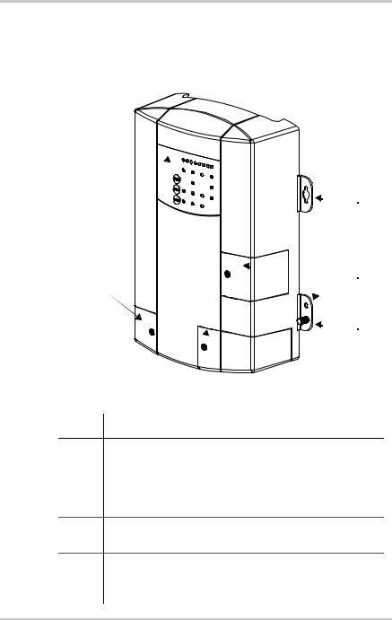
Truecharge™ 2 Battery Charger
This section describes the different parts of the Truecharge™ 2 Battery Charger.
1
2
3
4
5
6
Figure 1-1 Truecharge™ 2 Battery Charger
Item Description
1Onboard control and status display panel or simply onboard display (see “Rear Panel” on page 1–6 for more information) for controlling the Truecharge™ 2 Battery Charger settings and for monitoring charger status and charging current.
2Mounting flanges are used to permanently install the product.
3DC wiring compartment cover protects the DC terminals, as well as the communication and BTS ports. Remove and replace when installing cables.
1–4 |
975-0401-01-01 |

Truecharge™ 2 Battery Charger
Item Description
4Fuse access panel cover provides access to the DC fuse in the event of an accidental reverse battery polarity installation.
 WARNING: Shock hazard
Disconnect the batteries and AC power before opening the fuse access panel.
5AC wiring compartment cover provides the installer with easy access to the AC wiring compartment, to allow for a trouble free installation. Remove and replace when installing the product.
6DC ground stud for connecting the charger’s chassis to ground.
975-0401-01-01 |
1–5 |
Introduction
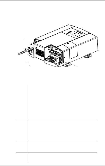
Rear Panel
This section describes the parts of the rear panel of the Truecharge™ 2 Battery Charger.
3
8 |
7 |
4 |
|
9
5


 2
2
6 |
1 |
|
40 A model (TC4012) shown. Other models may vary.
Figure 1-2 Truecharge™ 2 Battery Charger Rear Panel
Item |
Description |
|
|
1 |
BTS port- battery temperature sensor port |
|
|
2 |
Communication port - remote panel port |
|
|
3 |
Battery positive (+) for bank 3 (6 mm stud) |
|
|
4 |
Battery positive (+) for bank 2 (6 mm stud) |
|
|
5 |
Battery positive (+) for bank 1 (6 mm stud) |
6Battery negative (–), common for all three banks (6 mm stud)
(common for both banks in model TC1512) (model TC1012 has a single bank only–one positive terminal and one negative terminal)
7 |
Air intake vent - located inside is the fan assembly |
|
|
8 |
AC wiring compartment |
9AC pigtail wiring - line, neutral, and ground input wires
1–6 |
975-0401-01-01 |
Onboard Control and Status Display Panel
Onboard Control and Status Display Panel
This section describes the parts of the onboard control and status display panel of the Truecharge™ 2 Battery Charger.
Important: To prevent any unintentional changes in the setting, “press and hold” for three seconds any Select panel button to advance and pick the right setting.
To set and cancel an equalization program, “press and hold” for five seconds both the Charger Mode and Battery Temp. Select panel buttons.
1 |
|
3 |
|
4 |
2 |
5
6
Figure 1-3 Onboard Control and Status Display Panel
To reduce current draw from the connected battery when AC power is not present, the panel’s LED control and status lights are automatically turned off and the buttons are disabled.
However, to temporarily check the status of the connected battery when AC power is not present, press the Status button on the optional remote panel.
975-0401-01-01 |
1–7 |

Introduction
Item Description
1Charging Output (%) LEDs
•The LEDs illuminate like a bar graph displaying the present total output charge current as a percentage of the maximum rated charge current. For example, unit model TC4012 has a maximum rated charge current of 40 A so at 60% the charger’s current output is 24 A. The numbers below the LEDs represent the percentage values. See Figure 1-4 on page 1–10.
NOTE: When the maximum Charge Output current is limited via the optional Remote panel, the LEDs will still display the total charge output current as a percentage of the maximum rated charge current and NOT as a percentage of the limited charge current.
•One or two LEDs may flash intermittently in combination with a solid Fault LED (indicating a fault) or with a flashing Fault LED (indicating a warning). The icons above the LEDs represent the various types of fault and warning conditions. See Figure 1-4 on page 1–10.
2Fault LED
The LED may illuminate a solid light (indicating a fault) or flash intermittently (indicating a warning) in combination with flashing Charging Output (%) LEDs. See Table 1-1, “Fault and Warning Indicators” on page 1–11 for details.
3Charger Status LEDs
Displays the current status of the charger.
•Ready - a solid light indicates batteries are fully charged and the charger is not in float stage.
•Ready and Charging - solid lights indicate batteries are fully charged and the charger is in float stage.
•Charging - a solid light indicates charger is performing a normal charge cycle.
•Equalize - a solid light indicates that the charger is performing an
equalization cycle.
- a flashing light indicates that the equalization cycle will begin after the absorption stage is done.
1–8 |
975-0401-01-01 |

Onboard Control and Status Display Panel
Item Description
4Charger Mode Select button
•Press and hold the button for three seconds to select either of two settings. An indicator LED corresponds to each setting. Each setting optimizes the charging sequence differently in charging the batteries by stages.
•Three-stage - Bulk, Absorption, and Float; default setting
•Two-stage - Bulk and Absorption only
•When setting or cancelling an Equalization program: Press and hold for five seconds both the Charger Mode and Battery Temp. Select buttons.
5Battery Type Select button
Press and hold the button for three seconds to select either of five settings. An indicator LED corresponds to each setting. Each setting maximizes charger performance for its corresponding battery type.
•AGM - Absorbent Glass Mat lead-acid battery
•Flooded - Lead-acid battery; default setting
•GEL - Gel-type lead-acid battery
•Lead Calc. - Lead-calcium battery
•Custom - If a custom battery type has been programmed then all LEDs will illuminate
6Battery Temp. Select button
•Press and hold the button for three seconds to select one of three settings. An indicator LED corresponds to each setting.
When the optional BTS is not used, this selection changes the charger's output voltage settings to compensate for the battery temperature selected. The Cold setting raises the voltages, and the Hot setting lowers the voltages.
 WARNING: Risk of battery damage
Be sure the appropriate setting is selected before charging. For varying conditions, use the Warm setting.
975-0401-01-01 |
1–9 |
Introduction
Item |
Description |
||
|
|
|
|
6 |
• Cold - for battery temperature below 5 °C (41 °F); raises the |
||
continued |
|
charging voltage to compensate |
|
|
• Warm - for battery temperature between 5 and 30 °C |
||
|
|
(41 and 86 °F); default setting |
|
|
• Hot - for battery temperature above 30 °C (86 °F); lowers |
||
|
|
charging voltage to compensate |
|
|
• When setting or cancelling an Equalization program: Press and |
||
|
hold for five seconds both the Charger Mode and Battery Temp. |
||
|
Select buttons. |
||
|
|
The Fault LED works in conjunction with the Charging |
|
|
|
||
|
|
Current (%) LEDs. The icons at the top row above the |
|
|
|
Charging Current (%) LEDs represent the various types of |
|
|
|
fault and warning conditions. For example, a temperature |
|
|
|
warning is represented by a thermometer icon. |
|
|
|
The Charging Current (%) LEDs will normally illuminate as |
|
|
|
a solid progress bar when they are indicating the amount of |
|
|
|
output charging current. If any of the LEDs start to flash |
|
|
|
intermittently at the same time that the Fault LED is either |
|
|
|
solid or flashing, a fault or warning condition is indicated. |
|
|
|
|
|
|
|
Important: A warning condition notifies the user of an |
|
|
|
impending problem and will not stop the charger from |
|
|
|
charging, while a fault condition will stop the charger from |
|
|
|
charging the battery. |
|
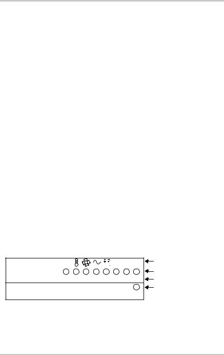
F |
C |
R |
Type of fault and warning |
u |
h |
e |
|
s |
g |
m |
|
e |
r |
Charging Output (%) LEDs |
|
Charging Output (%) |
|
|
|
<5 5 10 20 40 60 |
80 100 |
Charging Output (%) values |
|
|
|
|
Fault LED |
Fault
Figure 1-4 Charging Output (%) and Fault LEDs
1–10 |
975-0401-01-01 |
 Loading...