

XDL Series Digital
Programmable
Single Output DC
Power Supply
XDL 35-5T
XDL 35-5TP
Operating Manual

About Xantrex
Xantrex Technology Inc. is a world-leading supplier of advanced power electronics and controls
with products from 50 watt mobile units to one MW utility-scale systems for wind, solar, batteries,
fuel cells, microturbines, and backup power applications in both grid-connected and stand-alone
systems. Xantrex products include inverters, battery chargers, programmable power supplies,
and variable speed drives that convert, supply, control, clean, and distribute electrical power.
Trademarks
XDL series is a trademark of Xantrex International. Xantrex is a registered trademark of Xantrex
International.
Other trademarks, registered trademarks, and product names are the property of their respective
owners and are used herein for identification purposes only.
Notice of Copyright
© Xantrex International. All rights reserved.
Disclaimer
UNLESS SPECIFICALLY AGREED TO IN WRITING, XANTREX TECHNOLOGY INC.
(“XANTREX”)
(a) MAKES NO WARRANTY AS TO THE ACCURACY, SUFFICIENCY OR SUITABILITY OF
ANY TECHNICAL OR OTHER INFORMATION PROVIDED IN ITS MANUALS OR OTHER
DOCUMENTATION.
(b) ASSUMES NO RESPONSIBILITY OR LIABILITY FOR LOSS OR DAMAGE, WHETHER
DIRECT, INDIRECT, CONSEQUENTIAL OR INCIDENTAL, WHICH MIGHT ARISE OUT
OF THE USE OF SUCH INFORMATION. THE USE OF ANY SUCH INFORMATION WILL
BE ENTIRELY AT THE USER’S RISK.
Date and Revision
May 2004 - Revision 2
Part Number
975-0108-01-02
Contact Information
Telephone: 1-800-670-0707 (toll free in North America)
1-360-925-5097 (direct)
Fax: 1-360-925-5143
Email: Customerservice@xantrex.com
Web: www.xantrex.com
1

Table of Contents
Introduction 4
Specification 6
EMC 9
Safety 10
Installation 11
Connections 12
Initial Operation 14
Manual Operation 17
Remote Operation (XDL 35-5TP only) 27
Remote Commands 36
Maintenance 40
Calibration 40
Instructions en Francais
Sécurité 41
Installation 42
Connexions 43
Utilisation initiale 45
Fonctionnement manuel 48
Fonctionnement à distance (XDL 35-5TP seulement) 59
Commandes à distance 69
Maintenance 73
Bedienungsanleitung auf Deutsch
Sicherheit 74
Vorbereitung des Geräts 75
Anschlüsse 76
Erstmalige Inbetriebnahme 78
Manueller Betrieb 81
Fernbedienung (nur XDL 35-5TP) 92
Fernbedienungsbefehle 102
Wartung 106
2

Istruzioni in Italiano
Sicurezza 107
Installazione 108
Collegamenti 110
Primo utilizzo 112
Funzionamento in manuale 115
Funzionamento remoto (solo per il XDL 35-5TP) 126
Comandi remoti 136
Manutenzione 141
Instrucciones en Español
Seguridad 142
Instalación 143
Conexiones 144
Funcionamiento inicial 146
Funcionamiento manual 149
Funcionamiento Remoto (sólo XDL 35-5TP) 160
Comandos Remotos 170
Mantenimiento 175
Warranty Information 176
3

Unmatched Precision, Unrivalled Performance
The XDL series represents the ‘next generation’ of laboratory power supplies offering an
unparalleled level of precision.
Voltage and current are controlled using 16 bit DACs enabling voltages to be set to 1mV
resolution even at full output. Indeed, the accuracy is sufficient for the PSU to be used as a
calibration source for some hand-held DMMs.
The XDL series uses pure linear technology and offers unrivalled performance in terms of
regulation, output noise and dynamics. Line and load regulation are close to the limit of
measurement. Output noise is less than 350µV rms in CV mode and down to 20µA rms in CI
mode. Recovery time from transient current pulses is better than 50µs.
The XDL series provides full remote sense capability via dedicated sense terminals. Remote
sense is essential to maintain precise regulation at the load (two 0·02Ω connection leads will drop
200mV at 5 Amps). When remote sense is not required, internal local sensing can be selected at
the touch of a button.
Multiple Ranges for Greater Flexibility
The XDL series provides multiple ranges for increased current capability at lower voltages. The
main range offers 0 to 35 volts at up to 3 Amps. The higher current range provides up to 5 Amps
for voltages up to 15V. A further low current range provides enhanced current setting and
measurement resolution of 0·1mA.
Introduction
The product of voltage and current can be displayed at any time by pressing the VxA button. The
power is displayed to a resolution of 0·01 Watts.
Fast, Simple and Safe to use
The user interface of the XDL series has been carefully designed to provide rapid control whilst
guarding against any possibility of error.
Voltage and current setting can be performed either by direct numeric entry or, for applications
where the voltage or current must be gradually changed, by using the quasi-analogue Jog
control.
To enable the current limit to be set before connecting the load, the limit setting is displayed when
the output is off. Pressing the View Limits key at any time provides a temporary display of the limit
values allowing precise adjustment to also be made with the output on.
Setting Memories for Added Convenience
The XDL series provides storage of up to 10 power supply sets-ups in non-volatile memory for
each main output, plus a further 10 set-ups for linked mode operation. Upon mains switch-off, the
set-up of the PSU is saved and is automatically restored at switch-on.
OVP and OCP Trips with 'Alarm' Output
The XDL series provides fully adjustable over-voltage and over-current trips which can be used
both as a fail-safe against accidental mis-setting and as a protection against inappropriate load
conditions. In addition to turning the output off, a trip condition switches the rear panel alarm
signal enabling other equipment to be controlled.
4
For complete protection of the power supply, the trip will also be operated by over-temperature or
excess voltage on the sense terminals.
Fully Programmable via GPIB, RS232 or USB
The XDL 35-5TP incorporates a full bus interface permitting remote control and readback via
either GPIB (IEEE-488), RS232 or USB.
The GPIB interface conforms fully with IEEE-488.2 and IEEE-488.1.
The serial interface can be used as a conventional RS232 interface or as part of a multi-
instrument addressable RS232 chain.
USB represents the future for medium speed PC connectivity. By adding USB hubs, multiple
devices can be connected. A Windows device driver is supplied which creates a virtual COM
port, enabling USB to be used with applications that do not directly support it.
XDL series supplies use simple and consistent command structures which make programming
particularly easy regardless of which interface is used.
A National Instruments LabWindows* device driver is available.
All power supply settings can be controlled via the bus. Voltage and current can be set to a
resolution of 1mV or 0·1mA. Actual voltage and current can be read back together with the power
supply status.
* LabWindows is a trademark of National Instruments Corp.
5

General specifications apply for the temperature range 5°C to 40°C. Accuracy specifications
apply for the temperature range 18°C to 28°C after 1 hour warm-up with no load and calibration at
23°C. Typical specifications are determined by design and are not guaranteed.
MAIN OUTPUTS
Specification
Voltage/Current
Ranges:
Voltage Setting: Resolution 1mV
Current Setting: Resolution 1mA; 0·1mA on 500mA range
Output Mode: Constant voltage or constant current with automatic cross-over.
Output Switch: Electronic, non isolating. Switch illuminated when Output on.
Output Terminals: 4mm terminals on 19mm (0·75”) spacing for Output; screwless terminals
Transient Response:
Voltage Programming
Speed:
The 3 operating ranges are: 0V to 35V/0·001A to 3A
0V to 35V/0·1mA to 500mA
0V to 15V/0·001A to 5A
Accuracy ± (0·03% + 5mV)
Accuracy ± (0·2% + 5mA); ± (0·2% + 0·5mA) on 500mA range.
CI indicator lit in constant current mode.
Preset voltage and current limit displayed when Output off.
for Sense. Duplicate rear panel Output and Sense screw terminals on
remote control model (XDL 35-5TP).
<50µs to within 15mV of set level for a change in load current from full
load to half load or vice versa.
Maximum time required for output to settle within 1% of its total
excursion (for resistive load). Excludes command processing time.
No Load
6ms
7ms
40ms
250ms
600ms
600ms
Up 15V 5A
Up 35V 3A
Up 35V 500mA
Down 15V 5A
Down 35V 3A
Down 35V 500mA
Full Load
6ms
20ms
200ms
6ms
25ms
120ms
6
Ripple and Noise
(20MHz bandwidth):
Load Regulation: For any load change, measured at the output terminals, using
Line Regulation: Voltage <0·01% + 2mV for 10% line change.
Temperature
Coefficient:
Output Protection: Output will withstand forward voltages of up to 20V above rated output
Over-voltage
Protection:
(OVP)
Normal mode voltage: <0·35mVrms and 2mVp-p
Normal mode current: <0·2mArms; <20µArms on 500mA range.
remote sense.
Voltage <0·01% + 2mV.
Current <0·01% + 250µA; <0.01% +50µA on 500mA range.
Add typically 2·5mV for a 0·5V drop in the positive output lead.
Specification applies for sense lead resistance <0·5Ω.
Current <0·01% + 250µA; <0.01%+ 50µA on 500mA range.
Voltage: typically <(50ppm + 0·5mV)/°C
Current: typically <(100ppm + 1mA)/°C;
(100ppm + 0·1mA)/°C on 500mA range.
voltage. Reverse protection by diode clamp for currents up to 3A.
Range 1V to 40V
Resolution 0·1V; accuracy ± (2% + 0·5V)
Response time typically 100µs

Over-current Protection:
(OCP)
Range 0·01A to 5·5A
Resolution 0·01A; accuracy ± (0·2% + 0·01A)
Response time typically 35ms
Protection Functions: Output trips off for OVP, OCP, over-temperature and Sense miswiring.
METER SPECIFICATIONS (Main Outputs)
Display Type: 5-digit (Volts), 4-digit (Amps), 14mm (0·56") LED.
Voltage (CI mode): Resolution 10mV
Accuracy ± (0·1% of reading + 10mV)
Current (CV mode): Resolution 0·001A; 0·1mA on 500mA range
Accuracy ± (0·2% + 0·005A); ± (0·2% + 0·5mA) on 500mA range
V x A: Resolution 0·01W; 0·001W on 500mA range
Accuracy ± (0·3% + 0·05W); ± (0·3% + 0·005W) on 500mA range
AUXILIARY OUTPUT
Voltage: 2·7V, 3·3V or 5V, selectable by front panel switch.
Voltage Accuracy: ± 5%
Current Limit: 1A minimum
Output Protection: Output will withstand up to 16V forward voltage. Diode clamp reverse
protection for currents up to 3A.
Output Terminals: 4mm terminals on 19mm (0·75") spacing. Duplicate screwless
terminals on rear panel.
Ripple & Noise:
Typically <1mV rms
(20MHz bandwidth)
Load & Line Regulation: <1·0% for a 90% load change; 0·1% for a 10% line change.
Status Indication: Current limit lamp.
ALARM OUTPUT
Isolated rear-panel open-collector output signal. User can select output to be activated for either
OVP, OCP, Overtemperature or Sense miswiring, or for any of those four faults.
KEYBOARD & ROTARY CONTROL
All functions, including the selection and set-up of the remote control interfaces, can be set from
the keyboard. The rotary jog control can be used to adjust output voltage and current settings in
a quasi-analogue mode.
INTERFACES (XDL 35-5TP only)
Full remote control facilities are available through the optional RS232, GPIB and USB interfaces.
Setting and readback resolutions are the same as for the Output and Meter specifications
respectively.
RS232: Variable Baud rate, 19200 Baud maximum. 9-pin D-connector.
Single instrument or addressable RS232 chain operation.
IEEE-488: Conforming with IEEE488.1 and IEEE488.2
USB: Standard USB hardware connection.
Remote Command
Processing Time:
Typically <80ms between receiving the command terminator for a step
voltage change at the instrument and the output voltage beginning to
change.
7

GENERAL
AC Input: 230V AC or 115V AC ± 10%, 50/60Hz
Power Consumption: 500VA max.
Operating Range: +5ºC to +40ºC, 20% to 80% RH
Installation Category II
Storage Range:
Environmental: Indoor use at altitudes up to 2000m, Pollution Degree 2.
Cooling: Intelligent variable-speed fan.
Store/Recall: Up to 10 set-ups can be saved and recalled via the keyboard or
Safety:
EMC: Complies with EN61326
Size: 280 x 160 x 290mm (WxHxD), excluding feet and terminals.
Weight: 10·5kg
−40ºC to + 70ºC
Over-temperature trip shuts down output if internal temperatures
exceed predetermined thresholds.
remote interfaces.
Complies with EN61010−1
8

This instrument has been designed to meet the requirements of the EMC Directive 89/336/EEC.
Compliance was demonstrated by meeting the test limits of the following standards:
Emissions
EN61326 (1998) EMC product standard for Electrical Equipment for Measurement, Control and
Laboratory Use. Test limits used were:
a) Radiated: Class B
b) Conducted: Class B
c) Harmonics: EN61000-3-2 (2000) Class A; the instrument is Class A by product category.
Immunity
EN61326 (1998) EMC product standard for Electrical Equipment for Measurement, Control and
Laboratory Use.
Test methods, limits and performance achieved were:
a) EN61000-4-2 (1995) Electrostatic Discharge : 4kV air, 4kV contact, Performance A.
b) EN61000-4-3 (1997) Electromagnetic Field, 3V/m, 80% AM at 1kHz, Performance B.
EMC
c) EN61000-4-11 (1994) Voltage Interrupt, 1 cycle, 100%, Performance B.
d) EN61000-4-4 (1995) Fast Transient, 1kV peak (AC line), 0·5kV peak (DC Outputs),
e) EN61000-4-5 (1995) Surge, 0·5kV (line to line), 1kV (line to ground), Performance B.
f) EN61000-4-6 (1996) Conducted RF, 3V, 80% AM at 1kHz (AC line only; DC Output
According to EN61326 the definitions of performance criteria are:
Performance criterion A: ‘During test normal performance within the specification limits.’
Performance criterion B: ‘During test, temporary degradation, or loss of function or
performance which is self-recovering’.
Performance criterion C: ‘During test, temporary degradation, or loss of function or
performance which requires operator intervention or system reset occurs.’
Where Performance B is stated it is because DC Output regulation may deviate beyond
Specification limits under the test conditions. However, the possible deviations are still small and
unlikely to be a problem in practice.
Note that if operation in a high RF field is unavoidable it is good practice to connect the PSU to
the target system using screened leads which have been passed (together) through an absorbing
ferrite sleeve fitted close to the PSU terminals.
Cautions
Performance B.
connections <3m not tested), Performance B.
To ensure continued compliance with the EMC directive observe the following precautions:
a) after opening the case for any reason ensure that all signal and ground connections are
remade correctly and that case screws are correctly refitted and tightened.
b) In the event of part replacement becoming necessary, only use components of an identical
type, see the Service Manual.
9

Safety
This power supply is a Safety Class I instrument according to IEC classification and has been
designed to meet the requirements of EN61010-1 (Safety Requirements for Electrical Equipment
for Measurement, Control and Laboratory Use). It is an Installation Category II instrument
intended for operation from a normal single phase supply.
This instrument has been tested in accordance with EN61010-1 and has been supplied in a safe
condition. This instruction manual contains some information and warnings which have to be
followed by the user to ensure safe operation and to retain the instrument in a safe condition.
This instrument has been designed for indoor use in a Pollution Degree 2 environment in the
temperature range 5°C to 40°C, 20% - 80% RH (non-condensing). It may occasionally be
subjected to temperatures between +5°C and –10°C without degradation of its safety. Do not
operate while condensation is present.
Use of this instrument in a manner not specified by these instructions may impair the safety
protection provided. Do not operate the instrument outside its rated supply voltages or
environmental range.
WARNING! THIS INSTRUMENT MUST BE EARTHED
Any interruption of the mains earth conductor inside or outside the instrument will make the
instrument dangerous. Intentional interruption is prohibited. The protective action must not be
negated by the use of an extension cord without a protective conductor.
When the instrument is connected to its supply, terminals may be live and opening the covers or
removal of parts (except those to which access can be gained by hand) is likely to expose live
parts. The apparatus shall be disconnected from all voltage sources before it is opened for any
adjustment, replacement, maintenance or repair.
Capacitors inside the power supply may still be charged even if the power supply has been
disconnected from all voltage sources but will be safely discharged about 10 minutes after
switching off power.
Any adjustment, maintenance and repair of the opened instrument under voltage shall be avoided
as far as possible and, if inevitable, shall be carried out only by a skilled person who is aware of
the hazard involved.
If the instrument is clearly defective, has been subject to mechanical damage, excessive moisture
or chemical corrosion the safety protection may be impaired and the apparatus should be
withdrawn from use and returned for checking and repair.
Make sure that only fuses with the required rated current and of the specified type are used for
replacement. The use of makeshift fuses and the short-circuiting of fuse holders is prohibited.
Do not wet the instrument when cleaning it.
The following symbols are used on the instrument and in this manual:-
Earth (ground) terminal.
mains supply OFF.
l
mains supply ON.
10
alternating current (ac)
direct current (dc)
Fuse
Installation
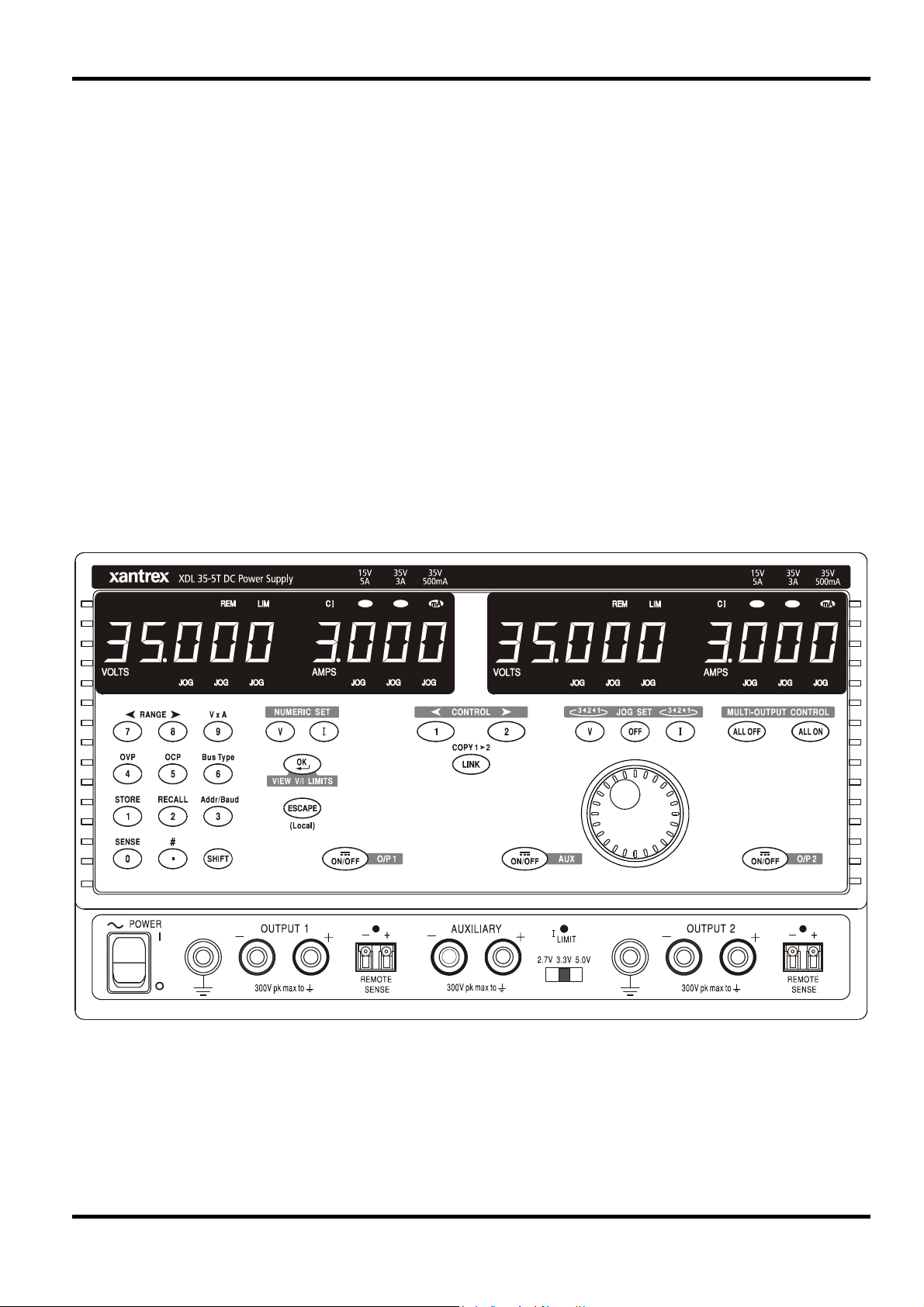
Check that the instrument operating voltage marked on the rear panel is suitable for the local
supply. Should it be necessary to change the operating voltage, proceed as follows:
1) Disconnect the instrument from all voltage sources.
2) Remove the screws which retain the top cover and lift off the cover.
3) Change the connections on both transformers following the appropriate diagram below:
BROW N BLUE BROWN BLUEBROW N
115V230V
4) Refit the cover and the secure with the same screws.
5) To comply with safety standard requirements the operating voltage marked on the rear panel
must be changed to clearly show the new voltage setting.
6) Change the fuse to one of the correct rating, see below.
The AC fuse is located in the fuse drawer in the lower part of the IEC inlet connector. To change
the fuse remove the line cord and open the fuse drawer with a suitable too.
The correct mains fuse type is 20 x 5mm 250V HBC time-lag with the following rating:
for 230V operation: 4A (T) 250V HBC
for 115V operation: 8A (T) 250V HBC
Make sure that only fuses with the required current rating and of the specified type are used for
replacement. The use of makeshift fuses and the short-circuiting of fuseholders are prohibited.
Mains Lead
When a three core mains lead with bare ends is provided it should be connected as follows:-
Any interruption of the mains earth conductor inside or outside the instrument will make the
instrument dangerous. Intentional interruption is prohibited. The protective action must not be
negated by the use of an extension cord without a protective conductor.
Mounting
This instrument is suitable both for bench use and rack mounting. It is delivered with feet for
bench mounting. The front feet include a tilt mechanism for optimal panel angle.
A rack kit for mounting XDL Series power supplies is available from the Manufacturers or their
overseas agents. The rack will accommodate 1, 2 or 3 single units or a triple and single unit; a
blanking piece is also available for unused positions in the rack.
Ventilation
The power supply is cooled by an intelligent multi-speed fan which vents at the rear. Take care
not to restrict the air inlets at the side panels or the exit at the rear. In rack-mounted situations
allow adequate space around the instrument and/or use a fan tray for forced cooling.
Brown - Mains Live
Blue - Mains Neutral
Green / Yellow - Mains Earth
WARNING! THIS INSTRUMENT MUST BE EARTHED
11

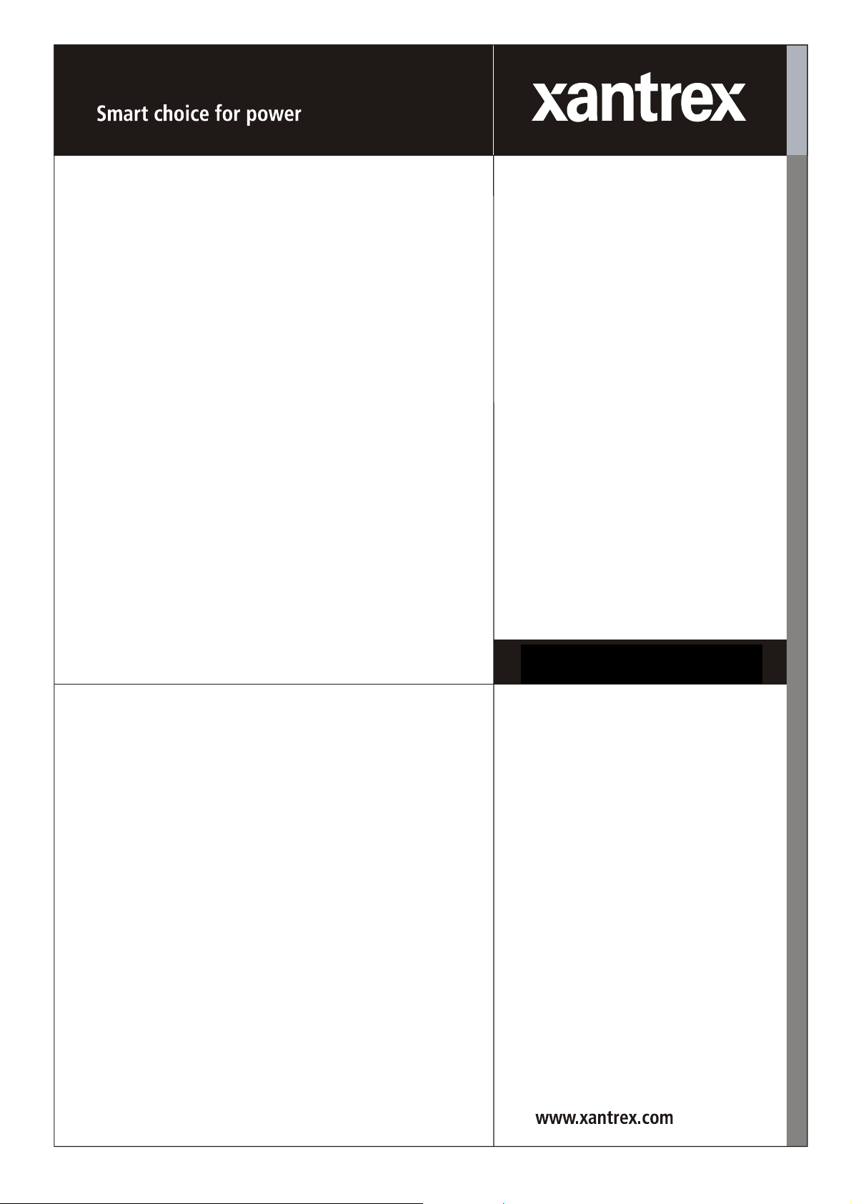
Front Panel Connections
The loads should be connected to the positive (red) and negative (black) terminals marked
OUTPUT 1, OUTPUT 2, or AUXILIARY.
Remote sense connections to the loads on Outputs 1 or 2, if required, are made from the
corresponding positive (+) and negative (−) REMOTE SENSE terminals. Remote sense
operation is selected from the keyboard or via a remote control interface (XDL 35-5TP only); the
REMOTE SENSE lamp is lit when remote sense is selected. Switching off remote sense returns
the instrument to local sensing at the output terminals.
Connections
The terminal marked
is connected to the chassis and safety earth ground.
Rear Panel Connections
Auxiliary Output Terminals
The front panel AUXILIARY OUTPUT terminals are duplicated on the rear panel with screwless
terminals marked AUXILIARY OUTPUT.
Main Output Terminals (XDL 35-5TP only)
The output and sense terminals are duplicated on the rear panel screw-terminal block marked
Output +, Output −, Sense + and Sense − ; these connections are paralleled with their front panel
equivalents.
Remote sense operation is selected from the keyboard or via a remote control interface. When
the rear panel terminals are used, remote sense should always be selected to ensure that output
regulation is maintained within specification.
RS232 (XDL 35-5TP only)
9−pin D−connector compatible with addressable RS232 use. The pin connections are shown
below:
Pin Name Description
1
2 TXD Transmitted data from instrument
3 RXD Received data to instrument
4
5 GND Signal ground
6
7 RXD2 Secondary received data
8 TXD2 Secondary transmitted data
9 GND Signal ground
−
−
−
No internal connection
No internal connection
No internal connection
12
Pin 2, 3 and 5 may be used as a conventional RS232 interface with XON/XOFF handshaking.
Pins 7, 8 and 9 are additionally used when the instrument is used in addressable RS232 mode.
Signal grounds are connected to instrument ground. The RS232 address is set from the
keyboard.

GPIB (XDL 35-5TP only)
The GPIB interface is not isolated; the GPIB signal grounds are connected to the instrument
ground.
The implemented subsets are:
The GPIB address is set from the keyboard.
USB (XDL 35-5TP only)
The USB port is connected to instrument ground. It accepts a standard USB cable. The
Windows plug-and-play functions should automatically recognise that the instrument has been
connected.
Alarm Outputs
Associated with each main output are recessed 2-pin connectors marked Alarm. These provide
access to an opto-isolated NPN switching transistor, the function of which can be set from the
keyboard, see the Alarms section of this manual.
The maximum operating voltage that can be applied across the terminals is 20VDC and the
maximum sink current for the switch 'closure' is 1mA.
Do not apply external voltages between the terminals exceeding 30VDC.
SH1 AH1 T6 TE0 L4 LE0 SR1 RL1 PP1 DC1 DT1 C0 E2
13

This section of the manual is a general introduction to the controls and operation of the
instrument and is intended to be read before using the power supply for the first time.
In this manual front panel keys, connections and display indicators are shown in capitals,
e.g. STORE, ESCAPE, OUTPUT, JOG. Messages shown on the 7-segment display are printed in
a different type-font, e.g.
characters as they are shown on the 7-segment display.
StorE, GPIb, triP in upper or lower case to represent the
Switching On, Output On/Off
The power switch is located at the bottom left of the front panel.
At power-up the default behaviour is for the instrument's settings to be restored to those
automatically saved when it was switched off, but with all Outputs always off. However, the user
can change the default setting such that selected Outputs are restored at power-up to their status
at power-down, see the Extra Functions section.
The DC outputs are switched electronically with their respective ON/OFF keys; the key
illuminates when the output is on. In addition, all outputs can be switched on and off together
using the ALL ON and ALL OFF keys.
Synchronous Output On/Off Switching
Pressing ALL OFF at any time will synchronously turn off any outputs that are on; under the same
load conditions outputs will typically turn off within 1ms of each other. With all outputs off the ALL
OFF key is illuminated green. Pressing the ALL ON key when all the outputs are off will turn all
the outputs on synchronously; outputs with identical settings and load conditions will typically turn
on within 1ms of each other. However, if one output is already on, pressing ALL ON will turn the
remaining outputs on but the turn-on delay between the outputs will be up to 80ms, even with the
same output setting and load conditions.
Initial Operation
Keypad
Only the principles of operation are outlined here; the setting of individual parameters is given in
detail in later sections.
The paramount consideration in designing the user interface has been to make changing settings
as 'safe' as possible (i.e. with minimal risk of accidentally applying excessive voltages to a target
system) whilst achieving ease of use. This has been achieved by requiring the user to confirm
(OK) new numeric settings, with the option to ESCAPE at any point or even to simply pause until
the operation times-out and the instrument returns to its orginal settings.
In addition a buzzer, illuminated keys, LED indicators and display messages prompt, guide or
warn the user such that entry or control errors are minimised. Where some of these features (e.g.
beeps or flashing indicators) are considered unnecessary by regular users, the option exists to
disable them, see the Extra Functions section.
The ability to change settings from the keypad or by using the Jog controls is assigned to
Output 1, Output 2 or both by using the 1, 2 or LINK CONTROL keys respectively. The key
(1 or 2) associated with the selected output illuminates to show which output is under control. In
LINK mode (both keys lit) both outputs are controlled at the same time, including some of the
shifted operations (RANGE, STORE, RECALL and V x A). The further descriptions that follow
apply to either or both main outputs as appropriate to the setting indicated by the illumination of
the CONTROL keys.
Under normal conditions the numeric keypad is disabled; pressing any key will cause the buzzer
to make a double beep, indicating an illegal operation. To set a voltage or current with the
keypad press the V or I NUMERIC SET key; the appropriate display shows 0·000V or 0·000A with
the digit to the left of the decimal point flashing. Digits are entered in response to the flashing
prompt, together with the decimal point at the appropriate time, and the entry is confirmed with
the OK key. If OK is not pressed within 10 seconds of the last numeric key the entry is cancelled
and the display returns to its original setting. If ESCAPE is pressed anywhere in the entry
procedure, entry is cancelled and the display returns to its original setting.
14

The OK key is used to confirm most keypad entries. At all other times it becomes the VIEW V/I
LIMITS key and pressing it will cause the display to show preset output voltage and current limit
for 3 seconds; during this period the LIM indicator in the display flashes.
Pressing SHIFT illuminates the key and gives the numeric keys the functions marked above them
(e.g. STORE, RECALL, etc.). When a function is selected by pressing one of these keys SHIFT
is cancelled (the SHIFT key is no longer lit). The further key presses required to complete the
selected function are described in detail in the sections that follow; if no key is pressed within 10
seconds to complete the function, the function with terminate as if ESCAPE has been pressed.
SHIFT is a toggle key; pressing SHIFT again when it has been selected will cancel SHIFT.
SHIFT is also cancelled by ESCAPE, or by pressing SET V or SET I. Note that in LINK mode
settings accessed by STORE and RECALL are specific to the LINK mode and are in addition to
settings accessible when STORE and RECALL are used on individually selected outputs.
Jog Control
The rotary 'jog' control permits the output voltage or current limit to be incremented or
decremented in steps with a resolution set by the JOG SET keys; the output immediately follows
the setting, i.e. no OK is required.
At power-up jog is always off. To jog the voltage or current setting press the V or I JOG SET key;
the key will illuminate and the JOG indicator under the digit that was last jogged will flash. Whilst
the V or I JOG SET key is lit, each further press of the V or I key moves the JOG indicator one
digit to the left; the selection 'wraps-round' such that when the largest value of jog increment has
been reached the next press returns it to the lowest. The default position at power-up is under
the LSD, i.e. the lowest jog increment is selected.
Turning the rotary jog control clockwise/anti-clockwise increments/decrements the selected digit;
digits to the left of the one being jogged are automatically incremented/decremented when the
decade overflow/underflow point is reached. Digits to the right of the one being jogged remain
unchanged unless the jog step overflows/underflows the range maximum/minimum in which case
they are set to zero. For example, 33·65V goes to 34·65V goes to 35·00V for the 35V range and
a 1V jog increment; 0·160A goes to 0·060A goes to 0·001A for a 0·1A jog decrement.
The jog steps that can be selected are 1mV, 10mV, 100mV and 1mA, 10mA, 100mA; if the
35V/500mA range has been selected the current increment steps are 0·1mA, 1mA, 10mA.
To disable the jog rotary control press the JOG SET OFF key; reselecting JOG SET V or I will
enable jog on the last used digit position. Jog is not cancelled by using numeric entry or any of
the SHIFT functions but it is disabled whilst that function is enabled.
When in constant voltage mode with the output on the right-hand display will show actual current
rather than current limit. If JOG SET I is selected the JOG indicator under the selected digit will
flash at half-speed ('lazy' flash). To observe the effect of jogging the current limit it will be
necessary to either turn the output off (so that the display permanently shows the current limit) or
to press VIEW V/I LIMITS which causes the current limit to be displayed until 3 seconds after
movement of the jog control ceases. The 'lazy' flash is also used when JOG SET V has been
selected and actual voltage is being shown because the supply has gone into current limit.
The factory default is to flash the JOG indicator under the selected digit for the whole time that
jog is selected so that the user is constantly reminded which parameter can be incremented/
decremented. Where this degree of reminding is considered inadequate the user can select,
using the Extra Functions capability, to flash the digit itself; conversely, where the flashing is
considered intrusive the user can select to not flash the JOG indicator (except when the 'lazy'
flash is shown).
15

Display
The displays shows the voltage on the left (5 digits) and the current on the right (4 digits) for both
the main outputs. These 7-segment displays are also used to show prompts during the some of
the function settings (e.g. memory store/recall or remote control address setting) using the limited
'character set' that can be achieved with a 7-segment display; these are necessarily a mixture of
upper and lower case letters.
Above and below the 7-segment display are several secret-until-lit annunciators. To the right,
above the current display, are the indicators which show the selected operating range:
35V/3A, 15V/5A or 35V/500mA; the indicators light beneath the range printed immediately above
them and, in the case of the 35V/500mA range, the indicator is marked mA to emphasise that the
current display is now showing mA. The other annunciators above the displays are:
CI, indicating that the instrument is in constant current mode; LIM, which flashes when the
VIEW V/I LIMITS key is pressed to show the set voltage/set current limit in the display; REM,
which lights when the instrument is under control from a remote interface (XDL 35-5TP only).
Below the three least significant digits of both the voltage and current displays are the JOG
indicators; the appropriate indicator flashes when the jog function is being used, see the Jog
Control section above.
16

Main Outputs
New users should first read the Initial Operation chapter which describes the operating principles
of the keypad and rotary jog control. The following paragraphs describe the independent
operation of either Main Output. To select which output is to be controlled by the keypad/Jog
controls it is first necessary to select that output by pressing the appropriate CONTROL key
(1 or 2); the key lights to show that it is the selected output.
The additional features available in LINK mode (both Main Outputs selected) are described in the
Main Outputs – Link Mode section later in this manual.
Set Voltage
The left-hand display shows the set voltage to a resolution of 1mV, except when the instrument is
in constant current (CI) mode. In CI mode the actual output voltage (which will be less than the
set voltage) is shown and the display resolution is 10mV; the least significant digit (1mV
resolution) is always displayed as a zero.
The voltage can be set directly from the numeric keypad: press the NUMERIC SET V key, enter
the new value using the numeric keys and confirm by pressing OK. The broad principles of
keypad entry are explained in the Initial Operation chapter, which should be read by new users.
Manual Operation
When SET V is pressed the display shows 0·000; a new voltage is then entered (e.g. 12·345V is
entered as 1, 2, ·, 3, 4, 5) and confirmed by OK. The position of the decimal point in the display is
fixed to reduce the risk of entering a wrong value. As a consequence, and to avoid the need to
enter leading zeroes (e.g. 2·345V is entered as 2, ·, 3, 4, 5, OK), numbers to the left of the
decimal point are shown slightly differently to the numbers to the right of the decimal point during
number entry; this is self-evident during number entry.
The minimum voltage setting is 0·000V; the maximum setting is 35·000V (15·000V on the 15V/5A
range).
Pressing OK at any point will set the voltage entered with any remaining digits set to zero,
e.g. 1, 2, ·, 3, OK will set 12·300V; 1, OK will set 1·000V; pressing OK immediately after SET V
(while the display shows 0·000V) will set 0·000V.
Pressing ESCAPE at any time during the sequence, or making no further key press within
10 seconds of the previous one will cause the display to return to its original reading before
SET V was pressed.
Entering a voltage outside the range maximum (including trying to enter 3 digits before the
decimal point) or trying to enter more than 5 digits will cause the buzzer to beep twice; the last
key entry will be ignored.
The voltage can also be set using the Jog control. Pressing JOG SET V will illuminate the V key
and the JOG indicator under the digit that was last jogged will flash. Whilst the V key is lit, each
further press will move the JOG indicator one digit to the left; the selection 'wraps round' such that
when the largest value of jog increment has been reached the next press returns it to the lowest.
The default position at power-up is under the LSD, i.e. the lowest jog increment is selected. The
jog steps that can be selected are 1mV, 10mV and 100mV.
With jog enabled the output voltage can be incremented or decremented with the rotary jog
control with a step resolution indicated by the position of the flashing JOG indicator. The output
immediately follows the setting, i.e. no OK is required. If the output goes into constant current
mode (indicated by the CI indicator flashing) the left-hand display shows actual voltage not set
voltage. If JOG SET V is selected the JOG indicator under the selected digit will flash at half
speed ('lazy' flash). To observe the effect of jogging the set voltage it will be necessary to either
turn the output off (so that the display permanently shows the set voltage) or to press
VIEW V/I LIMITS which causes the set voltage to be displayed until 3 seconds after movement of
the jog control ceases.
17

Note that in constant current mode the actual voltage is measured and displayed to only 10mV
resolution; the 1mV digit permanently displays zero.
Further details on the jog control can be found in the Initial Operation chapter.
Set Current Limit
With the output off, the right-hand display shows the current limit to a resolution of 1mA (0·1mA
on the 35V/500mA range).
The current limit can be set directly from the numeric keypad: press the NUMERIC SET I key,
enter the new value using the numeric keys and confirm by pressing OK. The broad principles of
keypad entry are explained in the Initial Operation chapter, which should be read by new users.
When SET I is pressed the display shows 0·000; a new current is then entered (e.g. 1·234A is
entered as 1, · , 2, 3, 4,) and confirmed by OK. The position of the decimal point in the display is
fixed to reduce the risk of entering a wrong value. As a consequence, and to avoid the need to
enter or display leading zeroes (e.g. 0·234A is entered as ·, 2, 3, 4, OK), numbers to the left of
the decimal point are shown slightly differently to the numbers to the right of the decimal point
during number entry; this is self-evident during number entry.
The minimum current setting is 0·001A (0·1mA on the 500mA range); the maximum setting is
3·000A, 5·000A or 500·0mA, according to range, i.e. there is no over-range capability.
Pressing OK at any point will set the current entered with any remaining digits set to zero,
e.g. 1, ·, 2, OK will set 1·200A; 1, OK will set 1·000A; pressing OK immediately after SET V (while
the display shows 0·000A) will set 0·00IA.
Pressing ESCAPE at any time during the sequence, or making no key press within 10 seconds of
the previous one will cause the display to return to its original reading before SET I was pressed.
Entering a value outside the range maximum (including trying to enter 2 digits before the decimal
point) or trying to enter more than 4 digits will cause the buzzer to beep twice; the last key entry
will be ignored.
The current limit can also be set using the rotary jog control. Pressing JOG SET I will illuminate
the key and the JOG indicator under the digit that was last jogged will flash. Whilst the I key is lit,
each further press will move the JOG indicator one digit to the left; the selection 'wraps round'
such that when the largest value of jog increment has been reached the next press returns it to
the lowest. The default position at power-up is under the LSD, i.e. the lowest jog increment is
selected. The jog steps that can be selected are 1mA, 10mA and 100mA (0·1mA, 1mA and 10mA
on the 35V/500mA range).
With jog enabled the current limit can be incremented or decremented with the rotary jog control
with a step resolution indicated by the position of the flashing JOG indicator. The output
immediately follows the setting, i.e. no OK is required. With the output on the right-hand display
shows actual current, not current limit (except in constant current mode). If JOG SET I is
selected the JOG indicator under the selected digit will flash at half speed ('lazy' flash). To
observe the effect of jogging the current limit it will be necessary to either turn the output off (so
that the display permanently shows the current limit) or to press VIEW V/I LIMITS which causes
the current limit to be displayed until 3 seconds after movement of the jog control ceases.
Instantaneous Current Output
18
The current limit control can be set to limit the continuous output current to levels down to 1mA
(0·1 mA on 500mA range). However, in common with all precision bench power supplies, a
capacitor is connected across the output to maintain stability and good transient response. This
capacitor charges to the output voltage and short-circuiting of the output will produce a current
pulse as the capacitor discharges which is independent of the current limit setting.

Range Selection
The instrument has three ranges: 35V/3A, 15V/5A and 35V/500mA. The selected range is shown
by an illuminated indicator below the appropriate legend at the top right-hand side of the
instrument; when the 35V/500mA range is selected the indicator legend is mA to emphasise that
the current meter now shows milliamps not amps.
To change range press SHIFT followed by RANGE or RANGE; each press of RANGE
selects the next range to the left; each press of RANGE selects the next range to the right;
there is no 'wrap-round'. When the range is changed the indicator that represents the new range
and the OK key both flash; pressing OK sets the new range. To exit without changing range
press ESCAPE. Pressing any other key whilst in range change mode causes the warning buzzer
to beep twice; no other action is taken. If OK is not pressed within 10 seconds of the last range
change key press the range selection remains unchanged.
The range can only be changed when the output is off. Pressing the RANGE or RANGE
keys with the output on will cause the output ON/OFF key (as well as the OK key) to flash. The
output may be turned off with the ON/OFF key and the range then changed by pressing OK, or
OK may be pressed directly in which case the output is automatically turned off and the range
then changed.
If a range change causes a voltage or current limit setting to exceed the corresponding maximum
of the new range the range change is accepted but the setting is made equal to the maximum of
the new range.
Note that the OVP setting is not changed when the range is changed (e.g. an OVP setting of 38V
remains valid on the 15V range); it is left to the user to independently change the OVP setting if
required.
Connection to the Load
The load should be connected to the positive (red) and negative(black) OUTPUT terminals. Both
are fully floating and either can be connected to ground.
Remote Sensing
The instrument has a very low output impedance, but this is inevitably increased by the
resistance of the connecting leads. At high currents this can result in significant differences
between the indicated source voltage and the actual load voltage (two 20mΩ connecting leads
will drop 0·2V at 5 Amps, for instance). This problem can be minimised by using short, thick,
connecting leads, but where necessary it can be completely overcome by using the remote sense
capability.
This requires the sense terminals to be connected to the output at the load instead of at the
source; insert wires into the spring-loaded REMOTE SENSE terminals and connect directly to the
load.
Select remote sense by pressing SHIFT, SENSE; the OK key flashes and the lamp above the
remote sense terminals lights to show that remote sense will be selected when OK is pressed.
Press OK to confirm; press ESCAPE to exit without changing state. Remote sense is turned off
by pressing SHIFT, SENSE again; the OK key flashes and the remote sense lamp goes off to
indicate that local sense will be restored when OK is pressed. Press OK to confirm; press
ESCAPE to exit without changing state.
To avoid instability and transient response problems, care must be taken to ensure good coupling
between each output and sense lead. This can be done either by twisting the leads together or by
using coaxially screened cable (sense through the inner). An electrolytic capacitor directly across
the load connection point may also be beneficial.
The voltage drop in each output lead must not exceed 0·5 Volts.
The XDL 35-5TP has rear panel output and sense terminals, appropriate for when the instrument
is used in a rack. The rear panel sense terminals should always be used with the rear panel
output connections.
19

Sense Miswiring Trip
The output will be tripped off if the voltage between an output terminal and its corresponding
sense terminal exceeds approximately 1V; this will happen if the sense wires are wired at the
load to the wrong output or if an attempt is made to draw power from the sense wires.
If the sense terminals are miswired in this way the display shows the message
and the output is turned off. Pressing ESCAPE at this point removes the message and the
display now shows the preset voltage and current limit. When the cause of the trip has been
corrected the output can be turned on again.
Series or Parallel Connection with Other Outputs
The outputs of the power supply are fully floating and may be used in series with other power
supply units to generate high DC voltages up to 300V DC.
The maximum permissible voltage between any terminal and earth ground (
WARNING! Such voltages are exceedingly hazardous and great care should be taken to shield
the output terminals for such use. On no account should the output terminals be touched when
the unit is switched on under such use. All connections to the terminals must be made with the
power switched off on all units.
It should be noted that the unit can only source current and cannot sink it, thus units cannot be
series connected in anti-phase.
The unit can be connected in parallel with others to produce higher currents. Where several units
are connected in parallel, the output voltage will be equal to that of the unit with the highest output
voltage setting until the current drawn exceeds its current limit setting, upon which the output will
fall to that of the next highest setting, and so on. In constant current mode, units can be
connected in parallel to provide a current equal to the sum of the current limit settings.
Note that the output terminals are rated at 15A maximum; if several outputs are operated in
parallel to source higher currents than this the junction should be made at a separate point, not
one of the terminals.
SENSE triP
) is 300VDC.
Over-Voltage Protection
Over-Voltage Protection (OVP) can be set from 1·0V to 40V. If the output voltage exceeds the set
OVP the output is immediately shut down (typically within 100µs), thus avoiding damage to the
circuit under test. The OVP circuit will protect against accidental excessive voltage settings from
the front panel or via the remote control interfaces, external voltages impressed across the output
terminals, or a failure in the control circuitry of the instrument itself.
To set OVP press SHIFT, OVP; the 100mV step JOG indicator will start flashing and the jog rotary
control can be used to increment/decrement the OVP setting in 100mV steps. Press OK to
confirm the new setting; to exit without entering a new value press ESCAPE. The factory default
setting is 40·0V.
If the OVP is tripped the display shows the message
Pressing ESCAPE at this point removes the message and the display now shows the preset
voltage and current limit. When the cause of the OVP has been removed (or the OVP limit
changed) the output can be turned on again.
Note that the OVP setting is not changed when the range is changed (e.g. an OVP setting of 38V
remains valid on the 15V range); it is left to the user to independently change the OVP setting if
required.
Note also that it is possible and valid to set OVP below the set voltage. If the supply is in
constant current mode the output voltage will be below the set voltage; OVP could be set such
that is was above the actual output voltage but below the set voltage. This could be used to trip
the output under a fault condition which caused the load impedance to increase and the actual
output voltage to therefore rise above the OVP point.
OUP triP and the output is turned off.
20

Over-Current Protection
Over-Current Protection (OCP) can be set from 0·01A to 5·5A. If the output current exceeds the
set OCP the output is shut down (typically within 35ms).
To set OCP press SHIFT, OCP; the 10mA step JOG indicator will start flashing and the jog rotary
control can be used to increment/decrement the OCP setting in 10mA steps. Press OK to confirm
the new setting; to exit without entering a new value press ESCAPE. The factory default setting
is 5·50A.
If the OCP is tripped the display shows the message
Pressing ESCAPE at this point removes the message and the display now shows the preset
voltage and current limit. When the cause of the OCP has been removed (or the OCP limit
changed) the output can be turned on again.
Note that as with OVP, the OCP setting is not changed when the range is changed.
Note also that is possible and valid to set OCP below the set current limit. For example, the
power supply may be used to repetitively test a unit under test (UUT) which normally takes a
peak current of, say, 2 Amps. However, a faulty UUT would take a current of more than 2 Amps
and would be damaged by being left in a 2 Amp current-limited state. In this case the current limit
could be set to 2·1A, say, and the OCP set to 2·0A to ensure that a faulty UUT will trip the supply
off.
Output Protection
In addition to OVP and OCP for forward over-voltage and over-current protection, the output is
protected from reverse voltages by a diode; the continuous reverse current must not exceed 3
Amps although transients can be much higher.
Output Power (V x A)
If SHIFT, V x A is pressed the voltage display shows the product of measured output voltage x
measured current and the current display shows
an instantaneous, not a continuous, reading of the output power; the reading is held whilst the
key is pressed. Pressing V x A cancels SHIFT. Jog is temporarily disabled (and the JOG
indicators are turned off) during the V x A display.
OCP triP and the output is turned off.
UA. V x A is a momentary function, i.e. it gives
Temperature Trip
If the safe internal temperature limit is exceeded because, for example, the fan vents have been
blocked, the output is turned off and the display will show
this point will do one of two things:
i. If the over-temperature condition has already cleared the message will be removed and the
display will show preset voltage and current limit. Assuming the cause of the over-temperature
has been rectified the output can be turned on again.
ii. If the instrument is still above the safe temperature limit the
slowly ('lazy' flash) until the instrument has cooled, at which point the display will show preset
voltage and current limit again. Assuming the cause of the over-temperature has been rectified
the output can be turned on again.
Alarm Output
The recessed 2-pin connector on the rear panel is directly connected to an opto-coupled NPN
switching transistor (pin 1 emitter, pin 2 collector) which is turned on (i.e. switch 'closure')
according to the conditions specified in the Extra Functions section, see later. The default
condition is switch closure for any trip condition (OVP, OCP, SENSE or OTP). The maximum
open-circuit voltage permitted across the switch is 30VDC and the nominal sink current for switch
closure is 1mA.
OtP triP. Pressing ESCAPE at
OtP triP message will flash
21

Store Settings
The instrument can store 10 set-ups for each output in non-volatile memory; the parameters
stored are range, voltage, current limit, OVP and OCP. The output state and remote sense
setting are not stored.
To store a set-up press SHIFT, STORE, store no., OK; the store no. is any key 0 to 9.
After key-presses SHIFT, STORE, the display shows
cancelled (the light goes off). At this point, pressing any number key will display that number in
place of the
e.g.
StorE 1.E, StorE 2.F . Any number of stores can be checked by pressing one
number after another (i.e. without having to press SHIFT, STORE each time) before the selection
is confirmed with the OK key. A full store can be overwritten with new settings. At any time
before the OK key is pressed the store function can be exited without saving a set-up by pressing
ESCAPE or by waiting 10 seconds from the last key entry.
– and show either E (store Empty) or F (store Full) beside it,
Deleting Stored Settings
Any store can be returned to 'empty' as follows: select the store by pressing SHIFT, STORE,
store no.; at that point press • . The display now shows
dELEt 2.F ; pressing OK deletes the content of the store.
Recall Settings
To recall a set-up press SHIFT, RECALL, store no., OK; the store no. is any key 0 to 9. After
key-presses SHIFT, RECALL, the display shows
(the light goes off). At this point, pressing any key 0 to 9 will preview the voltage and current
settings of that store number; the settings flash to indicate preview mode.
Any number of stores can be previewed by pressing one number after another (i.e. without having
to press SHIFT, RECALL each time) before the selection is confirmed with the OK key. Empty
stores are indicated by flashing
pressed the Recall function can be exited without recalling a set-up by pressing ESCAPE or by
waiting 10 seconds from the last key entry.
StorE - ; the SHIFT function is
dELEt in place of StorE , e.g.
rECAL – ; the SHIFT function is cancelled
– in every digit position. At any time before the OK key is
Settings may be recalled with the output on or off. However, if the recalled setting involves a
range change the output is turned off to avoid any 'glitches'. After pressing SHIFT, RECALL,
store no., the ON/OFF key will flash (as well as the OK key) if completing the recall involves a
range change. The output may be turned off with the ON/OFF key and the recall then completed
by pressing OK, or OK may be pressed directly in which case the output is automatically turned
off and the recall completed.
Extra Functions
Variations on some of the factory default functions can be set by the user by using the # extra
functions facility. Each function change, detailed in the list below is accessed by pressing SHIFT,
#, nn, when nn is the 2-digit number in the list below; the display changes to
SHIFT, # and the buzzer gives a confirmation beep when the 2-digit number entry is complete.
As indicated in the opening paragraph of this section, the # functions can be set independently
(i.e. differently) for each main output; note, however, that the #02, #03 and #21 functions which
apply to the Auxiliary Output can only be set when CONTROLis assigned to Output 1.
# Code Function
00 Main Output always off at power-up (factory default)
01 Main Output status at power-up the same as at last power-down
02 Aux Output always off at power up (factory default).
03 Aux Output status at power up the same as at last power down.
HASH No._ after
Set with control assigned to Output 1.
Set with control assigned to Output 1.
22

20 Alarm output 'open' for main Output off, 'closed' for main Output on
21 Alarm output 'closed' when Aux Output is in Current Limit.
Set with control assigned to Output 1; applies to Output 1 alarm only.
22 Alarm output 'closed' when over-temperature trip occurs
23 Alarm output 'closed' when sense trip occurs
24 Alarm output 'closed' when over-current trip occurs
25 Alarm output 'closed' when over-voltage trip occurs
26 Alarm output 'closed' when any trip occurs (factory default)
30 Buzzer off
31 Buzzer on (factory default). A single beep indicates confirmation, a double beep
indicates a wrong entry.
40 Jog digit flashes, JOG indicator only flashes when jog is 'hidden'
41 JOG indicator always flashes, except when 'hidden' (factory default)
42 JOG indicator doesn't flash, except when 'hidden' (lazy flash)
91 Loads default calibration parameters. Refer to Service Manual
92 Shows firmware version number in the display
93 Sets these # settings to their factory default
99 Enter calibration mode. Refer to Service Manual.
Factory Default Settings
The ex-factory default settings (which will apply at first power-up) are as follows:
Range: 35V/3A
Voltage: 1·000V
Current Limit: 1·000A
OVP: 40V
OCP: 5·5A
Output: Output off; local Sense
# Settings: 00 Main Output always off at power-up
02 Aux Output always off at power up (an Output 1 # function only).
26 Alarm output 'closed' when any trip condition occurs
31 Buzzer on
41 JOG indicator always flashes; 'lazy' flash when hidden
RS232: 9,600 Baud (XDL 35-5TP only)
Address: 11 (XDL 35-5TP only)
Error Messages
The following hardware errors are indicated by showing the appropriate error number in the display.
The OK key will flash and if pressed the error will be ignored and operation will continue as described.
Error No. Error Description Action on pressing OK
1 Calibration constants corrupted at power-up Loads default calibration parameters
2 # functions corrupted at power-up Loads default # settings
3 Power-down settings not correctly loaded at
power up
Switching the instrument off with the error message showing will leave all settings unchanged.
23
Loads factory default power-up
settings

Main Outputs – Link Mode
In Link mode, selected by pressing the LINK key, the key parameters of the two Main Outputs are
adjusted together; when Link mode has been selected both CONTROLkeys (1 and 2) are lit
to show that both outputs are selected.
The following paragraphs only describe the differences between independent and linked
operation; they should be read in conjunction with the corresponding paragraphs in the Main
Outputs section.
Linked Mode Operation − Overview
Control of the two main outputs can be "linked" so that changes are applied to both outputs
simultaneously. There can be several reasons for wanting to do this:
1. Series or Parallel Wiring
The user may wish to create an output with either twice the voltage or twice the current
capability, see the Series or Parallel Connection with Other Outputs section on page 20.
Linked mode provides a convenient means for controlling the two outputs when they are
series or parallel connected.
2. Tracking Voltages (or Currents)
When in linked mode, using Numeric Set will set equal voltages and/or currents on the two
outputs. Control of the outputs can also be linked with different voltages and/or currents set
on the outputs. Use of the Jog control will then make equal changes to the two outputs.
3. Simultaneous Recall of Stored Settings
Each output has its own set of 10 memories. However, when in linked mode, a further set of
10 memories is available which can store settings for both outputs. Voltages and currents
can be set individually for each output and the control put into linked mode before storing.
The stored settings can then be recalled to both outputs simultaneously.
Note:
The existing settings for Output 1 can be duplicated on Output 2 using the Copy function before
or after linking.
When in linked mode the control functions are limited to Set Range, Set Volts and Set Current
(Numeric Set and Jog set), plus Store and Recall. OVP, OCP and Sense cannot be changed
while in linked mode.
Control of On/Off for each output remains separate when in linked mode. To switch the outputs
On or Off together the Multi-Output Control buttons must be used which are independent of linked
mode.
Selecting Link Mode
The only constraint on selecting Link mode is that both Main Outputs must already be set to the
same Range; in particular, the outputs may be linked even if their output voltage and current limit
settings are different. Pressing LINK when different ranges are set will cause the buzzers to
sound twice and the Range indicator of the previously unselected output to flash for 2 seconds.
Selecting Link mode will cancel any Jog selection set on either Main Output.
Set Voltage and Set Current Limit
Setting the output voltage and current limit by numeric entry or Jog control is essentially the same
as for the outputs in independent mode. Using numeric entry the two outputs will be set to
exactly the same new voltage and current limit, irrespective of the settings at the time the outputs
were linked. Note that there can be a finite time difference between the changes on the two
outputs, even if they are changing from the same initial setting; typically this time difference
should be no more than 40ms (80ms max). However, if the settings were different at the time the
outputs were linked, changing the voltage or current limit using the Jog control will maintain the
difference between the two outputs by incrementing/decrementing each output by the same step,
24

i.e. the outputs will 'track' each other. Tracking will be maintained until one of the outputs reaches
the range limit, at which time each further Jog step will cause the buzzer to sound for that output
(but with the output remaining at the range limit) whilst the in-range output continues to change,
i.e. 'tracking' ceases and the outputs converge with each further step. If the increment/decrement
is reversed the new (smaller) difference between the outputs is maintained until one output
reaches the range limit in the other direction.
If Link mode is exited whilst Jog is selected, Jog continues to be active on the selected output.
Store and Recall
In Link mode a further 10 non-volatile memories are available which are quite separate from the
10 memories for each output in independent mode. The parameters stored are Range, Voltage,
Current Limit, OVP and OCP. Operation in Link mode is exactly as described in the Store, Recall
and Delete paragraphs of the Main Outputs section; the display messages described in these
sections appear in both displays when Link mode is selected.
OVP, OCP and Sense
OVP, OCP and Sense can only be set when either channel is independently selected. The
settings are maintained when Link mode is selected; OVP and OCP can be saved as part of a
Link mode set-up but the Sense setting cannot. If an attempt is made to change OVP, OCP or
Sense whilst in Link mode the display of Output 1 will flash SELCt 1or2 to remind the user
that these parameters must be set independently for each channel. Press ESCAPE to cancel the
flashing display, assign control to the appropriate channel using the CONTROL 1 or 2 keys
and set OVP, OCP, or Sense as described for the individual outputs.
Output Power
Pressing SHIFT, V x A causes the output power of both outputs to be displayed simultaneously in
their respective displays (V x A in the voltage display,
described for independent operation.
Extra Functions
The # functions described in the Extra Functions paragraph of the Main Outputs section can also
be set when the instrument is in Link mode; both displays will show
SHIFT, #. Any # function set in this way will of course be the same for both outputs. However,
the # functions can be different for each output if they are separately set whilst in independent
mode and the function selection will be maintained for each output even when the outputs are in
Link mode.
Bus Type and Address/Baud Rate
The Bus Type, Address and Baud Rate can only be selected when control is assigned to Output
2. The Output 2 display is used to show the parameters being set, exactly as described for
independent operation. If an attempt is made to set these parameters in Links mode, or with
Output 1 selected, the display of Output 1 flashes
Output 2. Press Escape to clear the display prompt (or wait for it to time out), then select
Output 2.
Main Outputs – Copy Function
UA in the current display) exactly as
HASH No._ after pressing
SELCt P.U._2 as a prompt to select
The principle settings of Output 1 can be copied to Output 2 using the Copy function, irrespective
of the CONTROL mode (1, 2 or LINK) currently selected. The parameters copied are Range,
Voltage, Current Limit, OVP and OCP; the status of Sense, ON/OFF, Jog and the Store contents
are not copied.
Pressing SHIFT, COPY 1>2 causes the Voltage, Current and Range settings of Output 1 to
appear on the displays of Output 2 in flashing mode; the OK key also flashes. Pressing OK
confirms and implements the Copy operation; pressing ESCAPE at that point abandons the
operation.
25

If the Copy operation will cause a range change to Output 2, and if Output 2 is ON, the Output 2
ON/OFF key also flashes and the output is turned OFF when OK is pressed; the output can also
be turned off directly with its ON/OFF key before OK is pressed.
Auxiliary Output
The AUXILIARY output can provide up to 1 Amp at 2.7V, 3.3V or 5.0V. The output voltage is set
by a front-panel slide-switch and the current limit is fixed at ≥1Amp. The output terminals are
duplicated on the rear panel (screwless terminals) for rack use; there is no remote sense
capability. The output is switched On and Off electronically by the front panel switch or via one of
the remote control interfaces; no other function can be remote controlled on this output. Current
Limit is indicated when the output voltage has dropped by ~100mV; at this point the output will
typically source 1.5A and will maintain this current as the load impedance is reduced to a shortcircuit. If a short-circuit is maintained the output will eventually enter thermal shutdown.
26

Remote Operation (XDL 35-5TP only)
The instrument can be remotely controlled via its RS232, USB or GPIB interfaces. When using
RS232 it can either be the only instrument connected to the controller or it can be part of an
addressable RS232 chain which permits up to 32 instruments to be addressed from one RS232
port.
The USB interface operates internally through the instrument's RS232 interface. USB remote
control consequently operates exactly as described for single-instrument RS232 use but via the
USB connector. The instrument operates at the maximum Baud rate (19200) in USB mode. The
virtual COM port on the controlling computer, which is set up using the driver software supplied,
must be set to the same Baud rate. Application software on the computer can then access the
instrument as if it is connected via the RS232 connector. The USB port cannot, however, be used
as part of an addressable RS232 chain.
Some of the following sections are general and apply to all modes (single instrument RS232,
USB, addressable RS232 chain and GPIB); others are clearly only relevant to a particular
interface or mode. It is only necessary to read the general sections plus those specific to the
intended remote control mode.
Remote command format and the remote commands themselves are detailed in the Remote
Commands chapter.
Control Bus, Instrument Address and Baud Rate Selection
For successful operation each instrument connected to a GPIB bus or addressable RS232 chain
must be assigned a unique address. For addressable RS232 all instruments in the chain must be
set to the same Baud rate.
To change the interface settings the CONTROL mode must first be set to 2 (i.e. Output 2 only
selected).
Press SHIFT, Bus Type to display the currently selected bus type. To change to another bus type
scroll through the available types using the rotary control until the required type is displayed.
Press OK to select the displayed type or ESCAPE to retain the previous selection.
Press SHIFT, Addr/Baud to display the currently selected instrument bus address. If the currently
selected bus type is RS232 then pressing Addr/Baud again displays the currently selected Baud
rate and repeated presses alternate between the two. To change the address scroll through the
available addresses using the rotary control when the address is displayed. The address can be
set between 1 and 31 inclusive and the same address is used for both GPIB and addressable
RS232; the address setting is ignored in USB mode. To change the Baud rate scroll through the
available rates using the rotary control when the Baud rate is displayed. Press OK to select the
last displayed address and Baud rate or ESCAPE to retain the previous selections. Note that
RS232 must be selected before the Baud rate can be selected; the Baud rate is fixed at
maximum (19200) for USB.
Remote/Local Operation
At power-on the instrument will be in the local state with the REM indicator off. In this state all
keyboard operations are possible. When the instrument is addressed to listen and a command is
received the remote state will be entered and REM will be turned on. In this state the keyboard is
locked out and remote commands only will be processed. The instrument may be returned to the
local state by pressing the LOCAL key; however, the effect of this action will only remain until the
instrument is addressed again or receives another character from the interface, when the remote
state will once again be entered.
27
RS232 Interface
RS232 Interface Connector
The 9-way D-type serial interface connector is located on the instrument rear panel. The pin
connections are as shown below:
Pin Name Description
1 - No internal connection
2 TXD Transmitted data from instrument
3 RXD Received data to instrument
4 - No internal connection
5 GND Signal ground
6 - No internal connection
7 RXD2 Secondary received data (addressable RS232 only)
8 TXD2 Secondary transmitted data (addressable RS232 only)
9 GND Signal ground (addressable RS232 only)
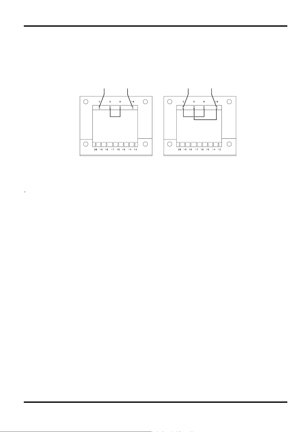
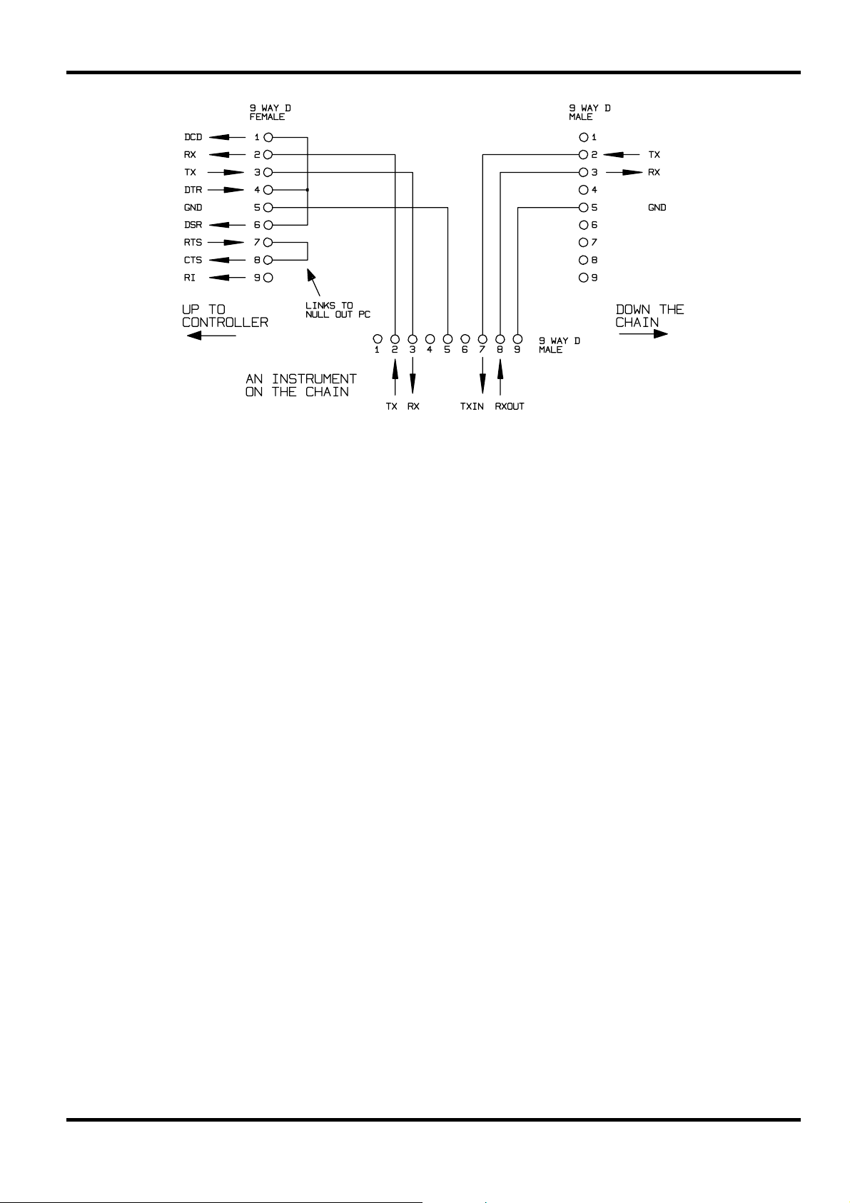
Single Instrument RS232 Connections
For single instrument remote control only pins 2, 3 and 5 are connected to the PC. However, for
correct operation links must be made in the connector at the PC end between pins 1, 4 and 6 and
between pins 7 and 8, see diagram. Pins 7 and 8 of the instrument must not be connected to the
PC, i.e. do not use a fully wired 9–way cable.
Baud Rate is set as described above in Address and Baud Rate Selection; the other parameters
are fixed as follows:
Start Bits: 1 Parity: None
Data Bits: 8 Stop Bits: 1
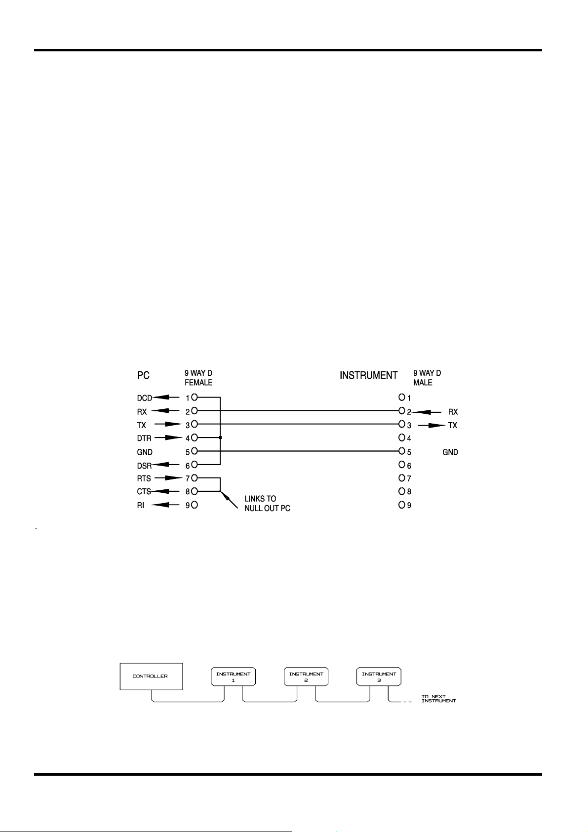
Addressable RS232 Connections
For addressable RS232 operation pins 7, 8 and 9 of the instrument connector are also used.
Using a simple cable assembly, a 'daisy chain' connection system between any number of
instruments, up to the maximum of 32 can be made, as shown below:
The daisy chain consists of the transmit data (TXD), receive date (RXD) and signal ground lines
only. There are no control/handshake lines. This makes XON/XOFF protocol essential and allows
the inter-connection between instruments to contain just 3 wires. The wiring of the adaptor cable
is shown below:
28
All instruments on the interface must be set to the same baud rate and all must be powered on,
otherwise instruments further down the daisy chain will not receive any data or commands.
The other parameters are fixed as follows:
Start Bits: 1 Parity: None
Data Bits: 8 Stop Bits: 1
RS232 Character Set
Because of the need for XON/XOFF handshake it is possible to send ASCII coded data only;
binary blocks are not allowed. Bit 7 of ASCII codes is ignored, i.e. assumed to be low. No
distinction is made between upper and lower case characters in command mnemonics and they
may be freely mixed. The ASCII codes below 20H (space) are reserved for addressable RS232
interface control. In this manual 20H, etc. means 20 in hexadecimal
Addressable RS232 Interface Control Codes
All instruments intended for use on the addressable RS232 bus use the following set of interface
control codes. Codes between 00H and 1FH which are not listed here as having a particular
meaning are reserved for future use and will be ignored. Mixing interface control codes inside
instrument commands is not allowed except as stated below for CR and LF codes and XON and
XOFF codes.
When an instrument is first powered on it will automatically enter the Non- Addressable mode. In
this mode the instrument is not addressable and will not respond to any address commands. This
allows the instrument to function as a normal RS232 controllable device. This mode may be
locked by sending the Lock Non-Addressable mode control code, 04H. The controller and
instrument can now freely use all 8 bit codes and binary blocks but all interface control codes are
ignored. To return to addressable mode the instrument must be powered off.
To enable addressable mode after an instrument has been powered on the Set Addressable
Mode control code, 02H, must be sent. This will then enable all instruments connected to the
addressable RS232 bus to respond to all interface control codes. To return to Non-Addressable
mode the Lock Non-Addressable mode control code must be sent which will disable addressable
mode until the instruments are powered off.
Before an instrument is sent a command it must be addressed to listen by sending the Listen
Address control code, 12H, followed by a single character which has the lower 5 bits
corresponding to the unique address of the required instrument, e.g. the codes A-Z or a-z give
the addresses 1-26 inclusive while @ is address 0 and so on. Once addressed to listen the
instrument will read and act upon any commands sent until the listen mode is cancelled.
29

Because of the asynchronous nature of the interface it is necessary for the controller to be
informed that an instrument has accepted the listen address sequence and is ready to receive
commands. The controller will therefore wait for Acknowledge code, 06H, before sending any
commands, The addressed instrument will provide this Acknowledge. The controller should timeout and try again if no Acknowledge is received within 5 seconds.
Listen mode will be cancelled by any of the following interface control codes being received:
12H Listen Address followed by an address not belonging to this instrument.
14H Talk Address for any instrument.
03H Universal Unaddress control code.
04H Lock Non-Addressable mode control code.
18H Universal Device Clear.
Before a response can be read from an instrument it must be addressed to talk by sending the
Talk Address control code, 14H, followed by a single character which has the lower 5 bits
corresponding to the unique address of the required instrument, as for the listen address control
code above. Once addressed to talk the instrument will send the response message it has
available, if any, and then exit the talk addressed state. Only one response message will be sent
each time the instrument is addressed to talk.
Talk mode will be cancelled by any of the following interface control codes being received:
12H Listen Address for any instrument.
14H Talk Address followed by an address not belonging to this instrument.
03H Universal Unaddress control code.
04H Lock Non-Addressable mode control code.
18H Universal Device Clear.
Talk mode will also be cancelled when the instrument has completed sending a response
message or has nothing to say.
The interface code 0AH (LF) is the universal command and response terminator; it must be the
last code sent in all commands and will be the last code sent in all responses.
The interface code 0DH (CR) may be used as required to aid the formatting of commands; it will
be ignored by all instruments. Most instruments will terminate responses with CR followed by LF.
The interface code 13H (XOFF) may be sent at any time by a listener (instrument or controller) to
suspend the output of a talker. The listener must send 11H (XON) before the talker will resume
sending. This is the only form of handshake control supported by addressable RS232 mode.
Full List of Addressable RS232 Interface Control Codes
02H Set Addressable Mode.
03H Universal Unaddress control code.
04H Lock Non-Addressable mode control code.
06H Acknowledge that listen address received.
30
0AH Line Feed (LF); used as the universal command and response terminator.
0DH Carriage Return (CR); formatting code, otherwise ignored.
11H Restart transmission (XON).
12H Listen Address - must be followed by an address belonging to the required instrument.
13H Stop transmission (XOFF).
14H Talk Address - must be followed by an address belonging to the required instrument.
18H Universal Device Clear.

USB Interface
The USB interface allows the instrument to be controlled using RS232 protocol via a computer’s
USB port. This is useful where the computer’s standard RS232 COM ports are fully utilised or
non-existent.
The instrument is supplied with a disk containing drivers for various versions of Windows,
including Win98 and 2000. The disk also contains a text file with information and details of the
software installation procedure.
Installation of the interface driver is achieved by connecting the instrument to a PC via a standard
USB cable. The Windows’ plug and play functions should automatically recognise the addition of
new hardware attached to the USB interface and if this is the first time the connection has been
made, prompt for the location of a suitable driver. Provided that the standard Windows prompts
are followed correctly Windows will install the appropriate driver and establish a virtual COM port
within the PC. The number of the new COM port will depend upon the number of co-existing
COM ports within the PC. The virtual COM port can be driven by Windows applications in exactly
the same way as a standard port.
Note that it is necessary to set the virtual COM port to the same Baud rate as the instrument
being controlled in exactly the same way as with a standard RS232 connection.
The driver will remain installed on the PC so that the establishment of a virtual COM port is done
automatically each time the instrument is connected to the PC via USB in the future.
Further virtual COM ports are created for each additional instrument connected to the PC via
USB. Each instrument is assigned a separate virtual COM port when it is first connected and the
same COM port will be assigned each time that instrument is subsequently connected; the PC
software makes use of the unique code embedded in each instrument to link it to the same virtual
COM port irrespective of which physical USB port it is connected to.
Use can also be made of the ADDRESS? command to easily identify which instrument is being
controlled by a particular COM port. Although the addressing capability is ignored in USB
operation the address can still be set and used as an identifier; set each USB-connected
instrument to a different address and send the ADDRESS? command from each virtual COM port
to confirm which instrument is connected to that port.
The supplied disk contains an uninstall program should this be required.
GPIB Interface
The GPIB interface 24-way connector is located on the instrument rear panel. The pin
connections are as specified in IEEE Std. 488.1-1987 and the instrument complies with IEEE Std.
488.1-1987 and IEEE Std. 488.2-1987.
GPIB Subsets
This instrument contains the following IEEE 488.1 subsets:
Source Handshake SH1
Acceptor Handshake AH1
Talker T6
Listener L4
Service Request SR1
Remote Local RL1
Parallel Poll PP1
Device Clear DC1
Device Trigger DT0
Controller C0
Electrical Interface E2
31

GPIB IEEE Std. 488.2 Error Handling – Query Error Register
The IEEE 488.2 UNTERMINATED error (addressed to talk with nothing to say) is handled as follows.
If the instrument is addressed to talk and the response formatter is inactive and the input queue is
empty then the
the Standard Event Status Register, a value of 3 to be placed in the Query Error Register and the
parser to be reset. See the Status Reporting section for further information.
UNTERMINATED error is generated. This will cause the Query Error bit to be set in
The IEEE 488.2
send a response message and a
or the input queue contains more than one END message then the instrument has been
INTERRUPTED and an error is generated. This will cause the Query Error bit to be set in the
Standard Event Status Register, a value of 1 to be placed in the Query Error Register and the
response formatter to be reset thus clearing the output queue. The parser will then start parsing
the next
<PROGRAM MESSAGE UNIT> from the input queue. See the Status Reporting section for
further information.
The IEEE 488.2
a response message and the input queue becomes full then the instrument enters the
state and an error is generated. This will cause the Query Error bit to be set in the Standard Event
Status Register, a value of 2 to be placed in the Query Error Register and the response formatter
to be reset thus clearing the output queue. The parser will then start parsing the next
MESSAGE UNIT>
GPIB Parallel Poll
Complete parallel poll capabilities are offered on this instrument. The Parallel Poll Enable
Register is set to specify which bits in the Status Byte Register are to be used to form the
message The Parallel Poll Enable Register is set by the *PRE <nrf> command and read by the
*PRE? command. The value in the Parallel Poll Enable Register is ANDed with the Status Byte
Register; if the result is zero then the value of
The instrument must also be configured so that the value of
during a parallel poll operation. The instrument is configured by the controller sending a Parallel
Poll Configure command (PPC) followed by a Parallel Poll Enable command (PPE). The bits in
the PPE command are shown below:
bit 7 = X don't care
bit 6 = 1
bit 5 = 1 Parallel poll enable
bit 4 = 0
bit 3 = Sense sense of the response bit; 0 = low, 1 = high
bit 2 = ?
bit 1 = ? bit position of the response
bit 0 = ?
INTERRUPTED error is handled as follows. If the response formatter is waiting to
<PROGRAM MESSAGE TERMINATOR> has been read by the parser
DEADLOCK error is handled as follows. If the response formatter is waiting to send
DEADLOCK
<PROGRAM
from the input queue. See the Status Reporting section for further information.
ist local
ist is 0 otherwise the value of ist is 1.
ist can be returned to the controller
Example. To return the RQS bit (bit 6 of the Status Byte Register) as a 1 when true and a 0 when
false in bit position 1 in response to a parallel poll operation send the following commands
*PRE 64
<pmt>, then PPC followed by 69H (PPE)
The parallel poll response from the instrument will then be 00H if RQS is 0 and 01H if RQS
is 1.
During parallel poll response the DIO interface lines are resistively terminated (passive
termination). This allows multiple devices to share the same response bit position in either wiredAND or wired-OR configuration, see IEEE 488.1 for more information.
32

Status Reporting
This section describes the complete status model of the instrument. Note that some registers are
specific to the GPIB section of the instrument and are of limited use in an RS232 environment.
Standard Event Status and Standard Event Status Enable Registers
These two registers are implemented as required by the IEEE Std. 488.2.
Any bits set in the Standard Event Status Register which correspond to bits set in the Standard
Event Status Enable Register will cause the ESB bit to be set in the Status Byte Register.
The Standard Event Status Register is read and cleared by the *ESR? command. The Standard
Event Status Enable register is set by the *ESE <nrf> command and read by the *ESE?
command.
Bit 7 - Power On. Set when power is first applied to the instrument.
Bit 6 - Not used.
Bit 5 - Command Error. Set when a syntax type error is detected in a command from the bus.
The parser is reset and parsing continues at the next byte in the input stream.
Bit 4 - Execution Error. Set when an error is encountered while attempting to execute a
completely parsed command. The appropriate error number will be reported in the
Execution Error Register.
1- 99 Indicates a hardware error has been encountered.
116 A recall of set up data has been requested but the store specified does not
contain any data.
117 A recall of set up data has been requested but the store specified contains
corrupted data. This indicates either a hardware fault or a temporary data
corruption which can be corrected by writing data to the store again.
120 The numerical value sent with the command was too big or too small. Includes
negative numbers where only positive numbers are accepted.
123 A recall/store of set up data has been requested from/to an illegal store number.
124 A range change has been requested but the current psu settings make it illegal –
see manual operation instructions for details.
Bit 3 - Verify Timeout Error. Set when a parameter is set with 'verify' specified and the value is
not reached within 5 secs, e.g. output voltage is slowed by a large capacitor on the
output.
Bit 2 - Query Error. Set when a query error occurs. The appropriate error number will be
reported in the Query Error Register as listed below.
1. Interrupted error
2. Deadlock error
3. Unterminated error
Bit 1 - Not used.
Bit 0 - Operation Complete. Set in response to the *OPC command.
Limit Event Status Registers and Limit Event Status Enable Registers
Two pairs of registers are implemented as an addition to the IEEE Std.488.2. Each pair consists of a
Limit Event Status Register and an accompanying Limit Status Event Enable Register. Limit Event
Status Register 1 (LSR1) and Limit Event Status Enable Register 1 (LSE1) apply to output 1. Limit Event
Status Register 2 (LSR2) and Limit Event Status Enable Register 2 (LSE2) apply to output 2 and the
Auxiliary output. Their purpose is to inform the controller of entry to and/or exit from current or voltage
limit conditions by storing a history of protection trip conditions since the last read.
Any bits set in a Limit Event Status Register which correspond to bits set in the accompanying
Limit Event Status Enable Register will cause the LIM1 or LIM2 bit to be set in the Status Byte
Register.
33

Limit Event Status Registers 1 and 2 are read and cleared by the LSR1? and LSR2? commands
respectively. Limit Event Status Enable Registers 1 and 2 are set by the LSE1<nrf> and
LSE2<nrf> commands and read by the LSE1? and LSE2? commands respectively.
Limit Event Status Register 1
Bit 7 - not used
Bit 6 - not used
Bit 5 - Set when an output 1 sense trip has occurred
Bit 4 - Set when an output 1 thermal trip has occurred
Bit 3 - Set when an output 1 over current trip has occurred
Bit 2 - Set when an output 1 over voltage trip has occurred
Bit 1 - Set when output 1 enters current limit (constant current mode)
Bit 0 - Set when output 1 enters voltage limit (constant voltage mode)
Limit Event Status Register 2
Bit 7 - not used
Bit 6 - Set when the Auxiliary output enters current limit
Bit 5 - Set when an output 2 sense trip has occurred
Bit 4 - Set when an output 2 thermal trip has occurred
Bit 3 - Set when an output 2 over current trip has occurred
Bit 2 - Set when an output 2 over voltage trip has occurred
Bit 1 - Set when output 2 enters current limit (constant current mode)
Bit 0 - Set when output 2 enters voltage limit (constant voltage mode)
Status Byte Register and Service Request Enable Register
These two registers are implemented as required by the IEEE Std. 488.2.
Any bits set in the Status Byte Register which correspond to bits set in the Service Request
Enable Register will cause the RQS/MSS bit to be set in the Status Byte Register, thus generating
a Service Request on the bus.
The Status Byte Register is read either by the *STB? command, which will return MSS in bit 6, or
by a Serial Poll which will return RQS in bit 6. The Service Request Enable register is set by the
*SRE <nrf> command and read by the *SRE? command.
Bit 7 - Not used.
Bit 6 - RQS/MSS. This bit, as defined by IEEE Std. 488.2, contains both the Requesting Service
message and the Master Status Summary message. RQS is returned in response to a
Serial Poll and MSS is returned in response to the *STB? command.
Bit 5 - ESB. The Event Status Bit. This bit is set if any bits set in the Standard Event Status
Register correspond to bits set in the Standard Event Status Enable Register.
Bit 4 - MAV. The Message Available Bit. This will be set when the instrument has a response
message formatted and ready to send to the controller. The bit will be cleared after the
Response Message Terminator has been sent.
Bit 3 - Not used.
Bit 2 - Not used.
Bit 1 - LIM2. This will be set if any bits in Limit Event Status Register 2 are set and corresponding
bits are set in Limit Event Status Enable Register 2.
Bit 0 - LIM1. This will be set if any bits in Limit Event Status Register 1 are set and corresponding
bits are set in Limit Event Status Enable Register 1.
34

Power on Settings
The following instrument status values are set at power on:
Status Byte Register = 0
Service Request Enable Register † = 0
Standard Event Status Register = 128 (pon bit set)
Standard Event Status Enable Register † = 0
Execution Error Register = 0
Query Error Register = 0
Parallel Poll Enable Register † = 0
† Registers marked thus are specific to the GPIB section of the instrument and are of limited use
in an RS232 environment.
The instrument will be in local state with the keyboard active.
The instrument parameters at power on are the same as at last switch off with the exception of
the output status. By default this is always off at power on but the user may change this to the
same at power on as at switch off.
Status Model
35

RS232 Remote Command Formats
Serial input to the instrument is buffered in a 256 byte input queue which is filled, under interrupt,
in a manner transparent to all other instrument operations. The instrument will send XOFF when
approximately 200 characters are in the queue. XON will be sent when approximately 100 free
spaces become available in the queue after XOFF was sent. This queue contains raw (unparsed) data which is taken, by the parser, as required. Commands (and queries) are executed in
order and the parser will not start a new command until any previous command or query is
complete. In non–addressable RS232 mode responses to commands or queries are sent
immediately; there is no output queue. In addressable mode the response formatter will wait
indefinitely if necessary, until the instrument is addressed to talk and the complete response
message has been sent, before the parser is allowed to start the next command in the input
queue.
Commands must be sent as specified in the commands list and must be terminated with the
command terminator code 0AH (Line Feed, LF). Commands may be sent in groups with
individual commands separated from each other by the code 3BH (;). The group must be
terminated with command terminator 0AH (Line Feed, LF).
Responses from the instrument to the controller are sent as specified in the commands list. Each
response is terminated by 0DH (Carriage Return, CR) followed by 0AH (Line Feed, LF).
Remote Commands
<WHITE SPACE> is defined as character codes 00H to 20H inclusive with the exception of those
which are specified as addressable RS232 control codes.
<WHITE SPACE> is ignored except in command identifiers. e.g. '*C LS' is not equivalent to '*CLS'.
The high bit of all characters is ignored.
The commands are case insensitive.
GPIB Remote Command Formats
GPIB input to the instrument is buffered in a 256 byte input queue which is filled, under interrupt,
in a manner transparent to all other instrument operations. The queue contains raw (un-parsed)
data which is taken, by the parser, as required. Commands (and queries) are executed in order
and the parser will not start a new command until any previous command or query is complete.
There is no output queue which means that the response formatter will wait, indefinitely if
necessary, until the instrument is addressed to talk and the complete response message has
been sent, before the parser is allowed to start the next command in the input queue.
Commands are sent as
or more
<PROGRAM MESSAGE UNIT> elements separated by <PROGRAM MESSAGE UNIT SEPARATOR>
elements.
<PROGRAM MESSAGE UNIT> is any of the commands in the remote commands list.
A
<PROGRAM MESSAGE UNIT SEPARATOR> is the semi-colon character ';' (3BH).
A
<PROGRAM MESSAGES> are separated by <PROGRAM MESSAGE TERMINATOR> elements which may
be any of the following:
NL The new line character (0AH)
NL^END The new line character with the END message
^END The END message with the last character of the message
Responses from the instrument to the controller are sent as
<RESPONSE MESSAGE> consists of one <RESPONSE MESSAGE UNIT> followed by a <RESPONSE
MESSAGE TERMINATOR>.
<RESPONSE MESSAGE TERMINATOR> is the new line character with the END message NL^END.
A
Each query produces a specific
the remote commands list.
<PROGRAM MESSAGES> by the controller, each message consisting of zero
<RESPONSE MESSAGE> which is listed along with the command in
<RESPONSE MESSAGES>. A
36

<WHITE SPACE> is ignored except in command identifiers. e.g. '*C LS' is not equivalent to '*CLS'.
<WHITE SPACE> is defined as character codes 00H to 20H inclusive with the exception of the NL
character (0AH).
The high bit of all characters is ignored.
The commands are case insensitive.
Command List
This section lists all commands and queries implemented in this instrument. The commands are
listed in alphabetical order within the function groups.
Note that there are no dependent parameters, coupled parameters, overlapping commands,
expression program data elements or compound command program headers; each command is
completely executed before the next command is started. All commands are sequential and the
operation complete message is generated immediately after execution in all cases.
The following nomenclature is used:
<rmt>
<RESPONSE MESSAGE TERMINATOR>
<nrf> A number in any format. e.g. 12, 12·00, 1·2 e1 and 120 e-1 are all accepted as the
number 12. Any number, when received, is converted to the required precision
consistent with the use then rounded up to obtain the value of the command.
<nr1> A number with no fractional part, i.e. an integer.
<nr2> A number in fixed point format e.g. 11·52, 0·78 etc.
<n> The number of the output or status register to which the command relates.
Note that <n>= 3 refers to the Auxiliary output.
The commands which begin with a
commands. All will function when used on the RS232 interface but some are of little use.
Instrument Specific Commands
For commands specified as 'WITH VERIFY' the Operation Complete message is generated when
the parameter being adjusted reaches the required value to within +/-5% or +/-10 counts,
whichever is the greater. If the value fails to settle to within these limits within 5 seconds then the
Verify Timeout bit (bit 3) is set in the Standard Event Status register and the Operation Complete
message will not be generated.
When the supply is operated in LINK mode, commands which set values and ranges are applied
to outputs 1 and 2 simultaneously, regardless of the whether <n> is set to 1 or 2. When the
command requests verification then verification will be sought from both outputs before the
command is completed. Additionally the SAV<n> and RCL<n> commands operate on non-volatile
memory reserved for linked mode set-ups and <n> may be set to 1 or 2 with the same effect.
Note however that <n> is part of the command header and must be included.
V<n> <nrf> set output <n> to <nrf> Volts
* are those specified by IEEE Std. 488.2 as Common
V<n>V <nrf> set output <n> to <nrf> Volts with verify
OVP<n> <nrf> set output <n> over voltage protection trip point to <nrf> Volts
I<n> <nrf> set output <n> current limit to <nrf> Amps
OCP<n> <nrf> set output <n> over current protection trip point to <nrf> Amps
V<n>? return the set voltage of output <n>
– response is V <n> <nr2><rmt> where <nr2> is in Volts
37

I<n>? return the set current limit of output <n>
– response is I <n> <nr2><rmt> where <nr2> is in Amps
OVP<n>? return the voltage trip setting for output <n>
– response is VP<n> <nr2><rmt> where <nr2> is in Volts
OCP<n>? return the current trip setting for output <n>
– response is IP<n> <nr2><rmt> where <nr2> is in Amps
V<n>O? return the output readback voltage for output <n>
– response is <nr2>V<rmt> where <nr2> is in Volts
I<n>O? return the output readback current for output <n>
– response is <nr2>A<rmt> where <nr2> is in Amps
RANGE<n> <nrf> set the voltage range of output <n> to <nrf> where <nrf> has the following
meaning:
0=15V(5A), 1=35V(3A), 2=35V(500mA)
RANGE<n>? return the set voltage range of output <n>
– response is R<n> <nr1><rmt> where <nr1> has the following meaning:
0=15V(5A), 1=35V(3A), 2=35V(500mA)
DELTAV<n> <nrf> set the output <n> voltage step size to <nrf> Volts
DELTAI<n> <nrf> set the output <n> current step size to <nrf> Amps
DELTAV<n>? return the output <n> voltage step size
– response is DELTAV<n> <nr2><rmt> where <nr2> is in Volts.
DELTAI<n>? return the output <n> current step size
– response is DELTAI<n> <nr2><rmt> where <nr2> is in Amps.
INCV<n> increment the output <n> voltage by the step size set for output <n>
INCV<n>V increment with verify the output <n> voltage by the step size set for output <n>
DECV<n> decrement the output <n> voltage by the step size set for output <n>
DECV<n>V decrement with verify the output <n> voltage by the step size set for output <n>
INCI<n> increment the output <n> current limit by the step size set for output <n>
DECI<n> decrement the output <n> current limit by the step size set for output <n>
OP<n> <nrf> set output <n> on/off where <nrf> has the following meaning: 0=OFF, 1=ON
set <n> to 3 to control the Auxiliary output
OPALL <nrf> Simultaneously sets all outputs on/off where <nrf> has the following meaning:
0=All OFF, 1=ALL ON.
If OPALL sets all outputs ON then any that were already on will remain ON
If OPALL sets all outputs OFF then any that were already off will remain OFF
SENSE<n> <nrf> set the output <n> sense mode where <nrf> has the following meaning:
0=local, 1=remote
38

MODE <nrf> set the instrument operating mode to LINK or assign control to output 1 or 2
<nrf> has the following meaning:
0 = linked, 1 = assign control to output 1, 2 = assign control to output 2.
Setting linked mode uniquely affects the way the instrument responds to some
remote commands. Assigning control to outputs 1 or 2 exits linked mode but has
no other affect until the instrument is returned to local operation.
Any operating mode set in remote operation will be retained when the
instrument is returned to local operation..
MODE? return the current operating mode
– response is LINKED or CTRL<n> (control assigned to output <n>)
TRIPRST attempt to clear all trip conditions from all outputs
LOCAL go to local
LSR<n>? query and clear LSR<n>, limit status register <n>
– response is <nr1><rmt>
LSE<n> <nrf> set the value of LSE<n>, limit status enable register <n>, to <nrf>
LSE<n>? return the value of LSE<n>, limit status enable register <n>
– response is <nr1><rmt>
SAV<n> <nrf> save the current set-up of PSU<n> to the set-up store specified by <nrf> where
<nrf> can be 0-9
If the instrument is operating in linked mode then the entire instrument set-up
will be stored in the linked mode set-up store specified by <nrf>. The <n>
specification is ignored. This has no affect on the individual PSU<n> set-up
stores available when not in linked mode
RCL<n> <nrf> recall a set up for PSU <n> from the set-up store specified by <nrf> where <nrf>
can be 0-9
If the instrument is operating in linked mode then the entire instrument set-up
will be recalled from the linked mode set-up store specified by <nrf>. The <n>
specification is ignored.
System and Status Commands
*RST
ER? Query and clear Execution Error Register. The response format is nr1<rmt>.
QER? Query and clear Query Error Register. The response format is nr1<rmt>
*CLS Clear Status. Clears the Standard Event Status Register, Query Error Register
*ESE <nrf> Set the Standard Event Status Enable Register to the value of <nrf>.
Resets the instrument to the factory default settings − (see Factory Defaults
section) with the exception of all remote interface settings.
and Execution Error Register. This indirectly clears the Status Byte Register.
*ESE? Returns the value in the Standard Event Status Enable Register in <nr1>
numeric format. The syntax of the response is <nr1><rmt>
*ESR? Returns the value in the Standard Event Status Register in <nr1> numeric
format. The register is then cleared. The syntax of the response is <nr1><rmt>
*IST?
39
Returns ist local message as defined by IEEE Std. 488.2. The syntax of the
response is 0<rmt>, if the local message is false, or 1<rmt>, if the local
message is true.

*OPC Sets the Operation Complete bit (bit 0) in the Standard Event Status Register.
This will happen immediately the command is executed because of the
sequential nature of all operations.
*OPC? Query Operation Complete status. The syntax of the response is 1<rmt>.
The response will be available immediately the command is executed because
of the sequential nature of all operations.
*PRE <nrf> Set the Parallel Poll Enable Register to the value <nrf>.
*PRE? Returns the value in the Parallel Poll Enable Register in <nr1> numeric format.
The syntax of the response is <nr1><rmt>
*SRE <nrf> Set the Service Request Enable Register to <nrf>.
*SRE? Returns the value of the Service Request Enable Register in <nr1> numeric
format. The syntax of the response is<nr1><rmt>
*STB? Returns the value of the Status Byte Register in <nr1> numeric format. The
syntax of the response is<nr1><rmt>
*WAI Wait for Operation Complete true. As all commands are completely executed
before the next is started this command takes no additional action.
Miscellaneous Commands
*IDN? Returns the instrument identification. The exact response is determined by the
instrument configuration and is of the form <NAME>,<model>, 0,
<version><rmt> where <NAME> is the manufacturer's name, <model> defines
the type of instrument and <version> is the revision level of the software
installed.
ADDRESS? Returns the bus address of the instrument. The syntax of the response is
<nr1><rmt>.
*TST? The PSU has no self test capability and the response is always 0 <rmt>
*TRG The PSU has no trigger capability.
Calibration Specific Commands
See Service Manual for details of calibration specific commands.
Error Messages
Each error message has a number; only this number is reported via the remote control interfaces.
Error message numbers are not displayed but are placed in the Execution Error Register where
they can be read via the remote interfaces, see Status Reporting section.
Maintenance
The Manufacturers or their agents overseas will provide a repair service for any unit developing a
fault. Where owners wish to undertake their own maintenance work, this should only be done by
skilled personnel in conjunction with the service manual which may be purchased directly from
the Manufacturers or their agents overseas.
Cleaning
If the instrument requires cleaning use a cloth that is only lightly dampened with water or a mild
detergent.
40
WARNING! TO AVOID ELECTRIC SHOCK, OR DAMAGE TO THE INSTRUMENT, NEVER
ALLOW WATER TO GET INSIDE THE CASE. TO AVOID DAMAGE TO THE CASE NEVER
CLEAN WITH SOLVENTS.

Routine calibration is carried out without opening the instrument.
Allow 10 minute warm-up before commencing calibration.
Equipment Required
A 5.5 digit multimeter with better than 0.02% accuracy on dc volts and better than 0.12%
accuracy on dc current (to 5A); alternatively use a precision shunt for current measurement.
Calibration
Assign CONTROL to Output 1. To enter calibration press SHIFT, #, 99. If the instrument is a long
way out of calibration, the default calibration values should be loaded first by pressing SHIFT, #,
91. Pressing ESCAPE at anytime will abort the calibration procedure and revert to the stored
calibration values.
Having entered calibration mode, follow the table below. To increment to the next step press OK.
The calibration must be done in sequence. At the end of calibration press OK to store the
calibration. The instrument automatically sets the range and settings at each step.
Use the spin-wheel to adjust calibration; holding down the JOG SET OFF key will give x100
increments to speed up calibration. Pressing SHIFT will show the calibration value.
Calibration
Repeat for Output 2.
Step/Range Settings Adjust for:- Load Detail
1, 35V 3A 0.01V 3A 10mV ± 0.5mV DVM o/p 0V
2, 35V 3A 0.01V 3A 0.010V on display DVM V readback zero
3, 35V 3A 35V 3A 35V ± 0.5mV DVM o/p V span
4, 35V 3A 35V 3A 35.000 on display DVM V readback span
5, 35V 3A 0.01V 3A 10mV ± 0.5mV DVM o/p 0V
6, 35V 3A 35V 3A 35V ± 0.5mV DVM o/p V span
7, 35V 3A 2V 0.001A 1mA ± 0.5mA milli-ammeter o/p A offset
8, 35V 3A 2V 0.001A 0.001 on display milli-ammeter A readback zero
9, 35V 500mA 2V 0.1mA 0.1mA ± 0.05mA milli-ammeter o/p mA offset
10, 35V 500mA 2V 0.1mA flashing 0.0/0.1 on display milli-ammeter mA readback zero
change load
11, 15V 5A 2V 4A 4A ± 0.5mA ammeter o/p A span
12, 15V 5A 2V 4A 4.000 on display ammeter A readback span
13, 15V 5A 2V 4.1A 4.100 on display ammeter A readback 13bit
14, 35V 500mA 2V 400mA 400mA ± 0.05mA ammeter o/p mA span
15, 35V 500mA 2V 400mA 400.0 on display ammeter mA readback span
16, 35V 500mA 2V 410mA 410.0 on display ammeter mA readback 13bit

Sécurité
Ce système alimentation est un instrument de classe de sécurité 1 conforme à la classification
IEC et il a été conçu pour satisfaire aux exigences de la norme EN61010-1 (Exigences de
sécurité pour les équipements électriques de mesure, de contrôle et d'utilisation en laboratoire). Il
s'agit d'un instrument de Catégorie II d'installation devant être exploité depuis une alimentation
monophasée standard.
Cet instrument a été testé conformément à la norme EN61010-1 et il a été fourni en tout état de
sécurité. Ce manuel d'instructions contient des informations et des avertissements qui doivent
être suivis par l'utilisateur afin d'assurer un fonctionnement et un état en toute sécurité.
Cet instrument a été conçu pour être utilisé en intérieur, en environnement de pollution de
deuxième degré (Pollution degree 2) à des plages de températures de 5°C à 40°C, et à des taux
d'humidité compris entre 20% et 80% (sans condensation). Il peut être soumis de temps à autre à
des températures comprises entre +5°C et –10°C sans dégradation de sa sécurité. Ne pas
l'utiliser en conditions de condensation.
Toute utilisation de cet instrument de manière non spécifiée par ces instructions risque d'affecter
sa protection de sécurité. Ne pas utiliser l'instrument hors des plages de tension d'alimentation
nominale recommandées ni hors de ses tolérances d'environnement.
AVERTISSEMENT ! CET INSTRUMENT DOIT ETRE RELIE A LA TERRE
Toute interruption du conducteur de la terre du secteur à l'intérieur ou à l'extérieur de l'instrument
rendra l'instrument dangereux. Il est absolument interdit de priver intentionnellement l'instrument
de son branchement à la terre. La sécurité de l'instrument ne doit pas être annulée par l'utilisation
de rallonge sans conducteur de protection.
Lorsque l'instrument est relié au secteur, il est possible que les bornes soient sous tension :
l'ouverture des couvercles ou la dépose de pièces (à l'exception des pièces accessibles
manuellement) risque de mettre à découvert des pièces sous tension. L'instrument doit être
débranché du secteur et de toute source d'alimentationavant tout réglage, remplacement, travaux
d'entretien ou de réparations.
Les condensateurs qui se trouvent dans le bloc d'alimentation risquent de rester chargés, même
si le bloc d'alimentation a été déconnecté de toutes les sources d'alimentation, mais ils se
déchargeront en toute sécurité environ 10 minutes après extinction de l'alimentation.
Eviter dans la mesure du possible d'effectuer des réglages, travaux de réparations ou d'entretien
lorsque l'instrument ouvert est branché au secteur. Si cela s'avère toutefois indispensable, seul
un technicien compétent connaissant les risques encourus doit effectuer ce genre de travaux.
S'il est évident que l'instrument est défectueux, qu'il a été soumis à des dégâts mécaniques, à
une humidité excessive ou à une corrosion chimique, la protection de sécurité est affaiblie :
l'instrument doit être retiré de l'exploitation et renvoyé vérifications et de réparations.
Ne remplacer les fusibles que par des fusibles d'intensité nominale requise et du type spécifié. Il
est interdit d'utiliser des fusibles "maison" et de court-circuiter des porte-fusibles.
Ne jamais humidifier l'instrument lors du nettoyage.
Les symboles suivants se trouvent sur l'instrument, ainsi que dans ce manuel.
Borne de terre (masse)
l
41
alimentation secteur ON (allumée)
alimentation secteur OFF (éteinte)
courant continu (c.c.)
courant alternatif (c.a.)

Installation
Vérifier que la tension de fonctionnement de l’instrument portée sur le panneau arrière convient à
l’alimentation locale. En cas de nécessité de changer de tension de fonctionnement, procéder
comme suit :
1) Déconnecter l’instrument de toutes les sources de tension.
2) Déposer les vis qui retiennent le couvercle supérieur et soulever ce dernier.
3) Modifier les connexions sur les deux transformateurs en suivant le schema approprié
ci-dessous :
4) Remonter le couvercle et le fixer à l’aide des mêmes vis.
5) Pour se conformer aux exigences des normes de sécurité, la tension de fonctionnement
portée sur le panneau arrière doit être modifiée pour indiquer clairement le réglage de
tension.
6) Remplacer le fusible par un fusible du bon calibre, voir ci-dessous.
Fusible
Le fusible CA se trouve dans le tiroir porte-fusible dans la partie inférieure du connecteur d’entrée
IEC. Pour changer de fusible, retirer le cordon et ouvrir le tiroir porte-fusible à l’aide d’un outil
adapté.
Le type correct de fusible secteur est 20 x 5mm 250V HBC à retardement, avec le calibre suivant:
Veiller à n’utiliser que des fusibles de l’ampérage requis et du type spécifié pour le
remplacement. L’utilisation de fusibles de fortune et la mise en court-circuit des portes-fusibles
sont interdits.
Cordon secteur
Lorsqu’un cordon secteur à trois fils à extrémités dénudées est fourni, il devra être connecté
comme suit :
Pour un fonctionnement à 230V : 2A (T) 250V HBC
Pour un fonctionnement à 115V :
Marron - Phase secteur
Bleu - Neutre secteur
Vert / jaune - Terre secteur
4A (T) 250V HBC
42
AVERTISSEMENT ! CET INSTRUMENT DOIT ETRE RELIE A LA TERRE
Toute interruption du conducteur de terre secteur à l’intérieur ou à l’extérieur de l’instrument
rendra l’instrument dangereux. L’interruption intentionnelle est interdite. L’action de protection ne
doit pas être anéantie par l’utilisation d’une rallonge sans conducteur de protection.

Montage
Cet instrument convient à la fois à l’utilisation sur établi et au montage en baie. Il est livré avec
des pieds pour le montage sur établi. Les pieds avant comprennent un mécanisme de
basculement pour obtenir l’angle optimal du panneau.
Un kit baie est disponible auprès des constructeurs ou de leurs agents à l’étranger pour le
montage des unités d’alimentation électrique série XDL. La baie acceptera 1, 2 ou 3 unités
simples ou une unité triple et une simple ; une pièce d’obturation est également disponible pour
les positions non-utilisées de la baie.
Ventilation
L’alimentation électrique est refroidie par un ventilateur intelligent à vitesses multiples qui ventile
à l’arrière. Prendre soin de ne pas limiter les arrivées d’air sur les panneaux latéraux ou la sortie
d’air à l’arrière. Dans les situations de montage en baie, laisser un espace adéquat autour de
l’instrument et/ou utiliser un bloc ventilateur pour un refroidissement forcé.
Connexions du panneau avant
Connexions
Les charges devront être connectées aux bornes positive (rouge) et négative (noire) repérées
OUTPUT 1, OUTPUT 2, ou AUXILIARY.
Les connexions de détection à distance aux charges sur les Sorties 1 ou 2, si nécessaire, se font
à partir des bornes de détection à distance REMOTE SENSE positive (+) et négative (−)
correspondantes. Le fonctionnement en détection à distance est sélectionné à partir du clavier ou
par l’intermédiaire d’une interface de télécommande (XDL 35-5TP seulement) ; le témoin
REMOTE SENSE est allumé lorsque la détection à distance est sélectionnée. Eteindre la
détection à distance renvoie l’instrument à la détection locale sur les bornes de sortie.
La borne marquée
est connectée au châssis et à la terre de sécurité.
Connexions du panneau arrière
Bornes de sorties auxiliaires
Les bornes AUXILIARY OUTPUT du panneau avant sont doublées sur le panneau arrière avec
des bornes sans vis portant les repères AUXILIARY OUTPUT.
Bornes de sorties principales (XDL 35-5TP seulement)
Les bornes de sortie et de détection sont doublées sur le bornier à vis du panneau arrière avec
les repères Output +, Output −, Sense + et Sense − ; ces connexions sont en parallèle avec leurs
équivalents du panneau avant.
Le fonctionnement en détection à distance est sélectionné à partir du clavier ou par
l’intermédiaire d’une interface de télécommande. Si l’on utilise les bornes du panneau arrière, la
détection à distance devra toujours être sélectionnée pour assurer que la régulation de sortie
sera maintenue dans les spécifications.
43

RS232 (XDL 35-5TP seulement)
Connecteur type D 9 broches compatible avec l’utilisation du RS232 adressable. La connexion
des broches est indiquée ci-dessous :
Broche Nom Description
1
2 TXD Données transmises par l’instrument
3 RXD Données reçues à l’instrument
4
5 GND Terre du signal
6
7 RXD2 Données secondaires reçues
8 TXD2 Données secondaires transmises
9 GND Terre du signal
Les broches 2, 3 et 5 peuvent être utilisées comme interface RS232 conventionnelle avec
établissement de liaison XON/XOFF. Les broches 7, 8 et 9 sont en outre utilisées lorsque
l’instrument est utilisé en mode RS232 adressable. Les terres de signaux sont connectées à la
masse de l’instrument. L’adresse RS232 est réglée à partir du clavier.
−
−
−
Pas de connexion interne
Pas de connexion interne
Pas de connexion interne
GPIB (XDL 35-5TP seulement)
L’interface GPIB n’est pas isolée ; les terres des signaux GPIB sont connectées à la masse de
l’instrument.
Les sous-ensembles mis en œuvre sont :
SH1 AH1 T6 TE0 L4 LE0 SR1 RL1 PP1 DC1 DT1 C0 E2
L’adresse GPIB est réglée à partir du clavier.
USB (XDL 35-5TP seulement)
Le port USB est connecté à la masse de l’instrument. Il accepte les câbles USB standard. Les
fonctions "plug-and-play" de Windows devraient automatiquement reconnaître le fait que
l’instrument a été connecté.
Sorties d’alarme
Associés à chaque sortie principale, il existe des connecteurs à 2 broches en retrait portant le
repère Alarme. Ils fournissent l'accès à un transistor de commutation NPN opto-isolé, dont la
fonction peut être réglée au clavier ; voir la section Alarmes de ce manuel.
La tension maximale de fonctionnement qui peut être appliquée entre les bornes est de 20V CC
et l’intensité maximale absorbée pour la 'fermeture' de l’interrupteur est de 1mA.
Ne pas appliquer entre les bornes de tensions externes dépassant 30V CC.
44

Cette section du manuel est une introduction générale aux commandes et au fonctionnement de
l’instrument et est censée être lue avant d’utiliser le générateur pour la première fois.
Dans ce manuel, les touches, connexions et indicateurs d’affichage du panneau avant sont
présentés en lettres capitales, par ex. STORE (enregistrer), ESCAPE (échap.), OUTPUT (sortie),
JOG (avance pas à pas). Les messages présentés sur l’afficheur à 7 segments sont imprimés
dans une police différente, par ex.
pour représenter les caractères tels qu’ils apparaissent sur l’afficheur à 7 segments.
StorE, GPIb, triP en majuscules ou minuscules
Mise en marche, Marche/Arrêt de sortie
L’interrupteur d’alimentation se trouve en bas à gauche du panneau avant.
A la mise sous tension, le comportement par défaut est la restauration des réglages de
l'instrument tels qu'ils ont été automatiquement sauvegardés lors de la mise hors tension de
l'appareil, amais avec toutes les Sorties toujours coupées. Cependant, l'utilisateur peut modifier
le paramètre par défaut de façon à ce que les Sorties sélectionnées soient restaurées à la mise
sous tension à leur statut à la mise hors tension, voir la section Fonctions Supplémentaires.
Les sorties CC sont commutée de façon électronique avec leurs touches ON/OFF (Marche/Arrêt)
respective ; la touche s'allume quand la sortie est active. De plus, toutes les sorties peuvent être
activées ou désactivées à l'aide des touches ALL ON (marche tout) et ALL OFF (arrêt tout).
Utilisation initiale
Commutation Marche/Arrêt synchronisée des sorties
Appuyer sur ALL OFF à tout moment va couper de façon synchronisée toutes les sorties actives;
dans les mêmes conditions de charge, les sorties se couperont en general en 1ms les unes des
autres. Une fois toutes les sorties coupées la touche ALL OFF s'allume en vert. Appuyer sur la
touche ALL ON lorsque toutes les sorties sont coupées va toutes les activer de façon
synchronisée ; les sorties dont les réglages et les conditions de charge sont identiques
s'allumeront en general en 1ms les unes des autres. Cependant, si une sorties est déjà active,
appuyer sur ALL ON activera le reste des sorties mais le délai d’allumage entre les sorties pourra
atteindre 80ms, même avec les mêmes réglages de sortie et les mêmes conditions de charge.
Clavier
Seuls les principes de fonctionnement sont définis ici, le réglage des paramètres individuels est
donné en détail dans les sections ultérieures.
La considération essentielle dans la conception de l’interface utilisateur a été de rendre les
changements de réglages aussi 'sûrs' que possible (c’est à dire avec un risque minime
d’appliquer accidentellement des tensions excessives à un système cible) tout en parvenant à la
facilité d’utilisation. Ceci a été réalisé en demandant à l’utilisateur de confirmer (OK) les
nouveaux réglages numériques, avec l’option ESCAPE pour s’échapper à tout moment ou même
simplement marquer une pause jusqu’à ce que l’opération arrive à échéance et que l’instrument
retourne à ses réglages d’origine.
De plus un bruiteur, des touches illuminées, des indicateurs à DEL et des messages à l’affichage
invitent, guident ou avertissent l’utilisateur de façon à minimiser les erreurs de saisie ou de
commande. Lorsque certaines de ces caractéristiques (par ex. bips ou indicateurs clignotants)
sont considérées inutiles par les utilisateurs réguliers, il existe l’option de les désactiver, voir la
section Fonctions supplémentaires.
La possibilité de changer les réglages au clavier ou en utilisant les commandes d'avance pas à
pas est assignée à la sortie 1, la sortie 2 ou les deux en utilisant les touches CONTROL 1, 2
ou LINK respectivement. La touche (1 ou 2) associée à la sortie sélectionnée s'allume pour
montrer quelle sortie est sous contrôle. En mode LINK, liaison, (les deux touches allumées) les
deux sorties sont contrôlées en même temps, y compris certaines des opérations accessibles
avec la touche Shift (RANGE, STORE, RECALL et V x A). Les plus amples descriptions qui
suivent s'appliquent à l'une ou l'autre des sorties principales ou aux deux le cas échéant pour le
réglage indiqué par l'éclairage des touches CONTROL.
45

Dans les conditions normales, le clavier numérique est désactivé ; le bruiteur émettra un double
bip si l’on appuie sur une touche, indiquant une opération illégale. Pour régler la tension ou
l’intensité avec le clavier, appuyer sur la touche NUMERIC SET V ou I (réglage numérique) ;
l’affichage approprié donne 0,000V ou 0,000A, le chiffre à gauche de la virgule décimale
clignotant. Les chiffres sont saisis en réponse à l’invite clignotante, ainsi que la virgule décimale
au moment approprié, et la saisie est confirmée avec la touche OK. Si l’on n’appuie pas sur la
touche OK dans les 10 secondes qui suivent l’utilisation de la dernière touche numérique, la
saisie est annulée et l’affichage revient à sa présentation d’origine. Si l’on appuie sur ESCAPE
n’importe où dans la procédure de saisie, la saisie est annulée et l’affichage revient à sa
présentation d’origine.
La touche OK est utilisée pour confirmer la plupart des entrées au clavier. Le reste du temps, elle
devient la touche VIEW V/I LIMITS (voir les limites V/I) et appuyer sur cette touche affichera la
limite de tension et d’intensité de sortie préréglées pendant 3 secondes ; durant cette période,
l’indicateur LIM clignote sur l’afficheur.
Appuyer sur SHIFT illumine la touche et donne accès aux fonctions marquées au-dessus des
touches numériques (par ex. STORE, RECALL (rappeler), etc.). Lorsque l’on sélectionne une
fonction en appuyant sur l’une de ces touches, SHIFT est annulé (la touche SHIFT n’est plus
allumée). Les actions sur les autres touches nécessaires pour mener à bien la fonction
sélectionnée sont décrites en détail dans les sections qui suivent ; si aucune touche n’est
actionnée dans les 10 secondes pour réaliser la fonction, celle-ci prend fin comme si l’on avait
appuyé sur ESCAPE. SHIFT est une touche à basculement : appuyer de nouveau sur SHIFT
quand elle a été sélectionnée annule son effet. SHIFT est également annulé par ESCAPE, ou en
appuyant sur SET V (régler V) ou SET I (régler I). Noter qu'en mode LINK les réglages
accessibles avec STORE et RECALL sont spécifiques au mode LINK et s'ajoutent à ceux
accessibles lorsque STORE et RECALL sont utilisées sur les sorties sélectionnées
individuellement.
Commande pas à pas
La commande rotative 'pas à pas' permet d’incrémenter ou de décrémenter la limite de tension ou
d’intensité de sortie par pas avec une résolution réglée par les touches JOG SET (régler pas à
pas) ; la sortie suit immédiatement le réglage, c’est à dire qu’il n’y a pas besoin de OK.
A la mise sous tension, la fonction pas à pas est toujours désactivée. Pour régler pas à pas la
tension ou l’intensité, appuyer sur la touche JOG SET V ou I ; la touche s’illumine et l’indicateur
JOG va clignoter sous le chiffre qui a été utilisé le dernier en pas à pas. Tant que la touche JOG
SET V ou I est allumée, chaque nouvel appui sur la touche V ou I déplace l’indicateur JOG d’un
chiffre sur la gauche ; la sélection 'tourne sur elle-même' de telle sorte que, quand la plus grande
valeur d’incrément pas à pas a été atteinte, l’appui suivant la renvoie à la plus basse. La position
par défaut à la mise sous tension est sous le chiffre le moins significatif, c’est à dire que le plus
faible incrément pas à pas est sélectionné.
Tourner la molette rotative dans le sens horaire ou antihoraire incrémente ou décrémente le
chiffre sélectionné ; les chiffres à gauche de celui qui est réglé pas à pas sont automatiquement
incrémentés ou décrementés lorsque le point de passage à la dizaine supérieure ou inférieure
est franchi. Les chiffres à droite de celui que l’on règle pas à pas restent inchangés jusqu’à ce
que le réglage pas à pas franchisse le maximum ou le minimum de la plage, auquel cas ils sont
réglés à zéro. Par exemple, 33,65V passe à 34,65V puis à 35,00V pour la plage 35V avec un
incrément pas à pas de 1V ; 0,160A passe à 0,060A puis à 0,001A pour un décrément pas à pas
de 0,1A.
Les pas de réglage que l’on peut sélectionner sont 1mV, 10mV, 100mV et 1mA, 10mA, 100mA; si
la plage 35V/500mA a été sélectionné, les pas d’incrémentation d’intensité seront 0,1mA, 1mA,
10mA.
Pour désactiver la molette rotative pas à pas, appuyer sur la touche JOG SET OFF (désactivation
du pas à pas) ; resélectionner JOG SET V ou I permettra de revenir en pas à pas sur la position
du dernier chiffre utilisé. Le pas à pas n’est pas annulé par l’utilisation de la saisie numérique ni
par une des fonctions SHIFT, mais il est désactivé tant que cette fonction est activée.
46

Lorsque l’instrument est en mode de tension constante avec la sortie sur la droite, l’affichage
montre l’intensité réelle plutôt que la limite d’intensité. Si on sélectionne JOG SET I, l’indicateur
JOG va clignoter à mi-vitesse sous le chiffre sélectionné (clignotement 'paresseux'). Pour
observer l’effet du réglage pas à pas de la limite d’intensité, il sera nécessaire soit de couper la
sortie (de façon à ce que l’affichage montre de façon permanente la limite de sortie), soit appuyer
sur VIEW V/I LIMITS, ce qui provoque l’affichage de la limite d’intensité encore 3 secondes après
que le mouvement de la molette pas à pas cesse. Le clignotement 'paresseux' est également
utilisé lorsque JOG SET V a été sélectionné et que la tension réelle est présentée parce que
l’alimentation a atteint la limite d’intensité.
Le réglage par défaut d’usine est le clignotement de l’indicateur JOG sous le chiffre sélectionné
tout le temps que le réglage pas à pas est sélectionné, de façon à rappeler constamment à
l’utilisateur le paramètre qui peut être incrémenté ou décrémenté. Lorsque ce degré de rappel est
considéré inadéquat, l’utilisateur pet sélectionner, à l’aide des Fonctions supplémentaires, de
faire clignoter le chiffre lui-même ; à l’opposé, lorsque le clignotement est considéré intrusif,
l’utilisateur peut choisir de ne pas faire clignoter l’indicateur JOG (excepté lorsque le clignotement
'paresseux' est utilisé).
Affichage
Les affichages montrent la tension sur la gauche (5 chiffres) et l'intensité sur la droite (4 chiffres)
pour les deux sorties principales. Ces affichages à 7 segments sont également utilisés pour
présenter des invites lors de certains réglages de fonctions (par ex. l’enregistrement ou le rappel
en mémoire ou le réglage d’adresses de télécommande) à l’aide du 'jeu de caractères' limité qui
peut être obtenu avec un affichage à 7 segments ; il s’agit nécessairement d’un mélange de
lettres majuscules et minuscules.
Au-dessus et au-dessous de l’affichage à 7 segments se trouvent plusieurs avertisseurs secrets
jusqu’à ce qu’ils s’allument. Sur la droite, au-dessus de l’affichage d’intensité, se trouvent des
indicateurs qui donnent la plage de fonctionnement sélectionnée : 35V/3A, 15V/5A ou
35V/500mA ; les indicateurs s’allument sous la plage inscrite immédiatement au-dessus d’eux et,
dans le cas de la plage 35V/500mA, l’indicateur est marqué mA pour mettre l’accent sur le fait
que l’affichage d’intensité est maintenant présenté en mA. Les autres avertisseurs au-dessus des
affichages sont : CI, indiquant que l’instrument est en mode d’intensité constante ; LIM, qui
clignote lorsque l’on actionne la touche VIEW V/I LIMITS pour voir la limite de tension/intensité
réglée à l’affichage ; REM, qui s’allume lorsque l’instrument est sous le contrôle d’une interface
distante (XDL 35-5TP seulement).
Au-dessous des trois chiffres les moins significatifs des affichages de tension et d’intensité, se
trouvent les indicateurs JOG ; l’indicateur approprié clignote lorsque la fonction de réglage pas à
pas est utilisée, voir la section Commande pas à pas ci-dessus.
47

Les nouveaux utilisateurs devront d’abord lire le chapitre Utilisation initiale qui décrit les principes
de fonctionnement du clavier et de la molette de commande pas à pas. Les paragraphes
suivants décrivent le fonctionnement indépendant de l'une ou l'autre sortie principale. Pour
sélectionner la sortie qui doit être contrôlée par le clavier ou les commandes pas à pas, il est
d'abord nécessaire de sélectionner cette sortie en appuyant sur la touche CONTROL
appropriée (1 ou 2) ; la touche s'allume pour montrer qu'il s'agit de la sortie sélectionnée.
Les fonctions supplémentaires disponibles en mode LINK (les deux sorties principales
sélectionnées) sont décrites dans la section Sorties principales – mode Link plus loin dans ce
manuel.
Réglage de la tension
L’affichage de gauche montre la tension réglée avec une résolution de 1mV, excepté quand
l’instrument est en mode d’intensité constante (CI). En mode CI, la tension de sortie réelle (qui
sera inférieure à la tension réglée) est indiquée, et la résolution d’affichage est de 10mV ; le
chiffre le moins significatif (résolution 1mV) est toujours affiché sous forme d’un zéro.
La tension peut être réglée directement à partir du clavier numérique : appuyer sur la touche
NUMERIC SET V (réglage numérique de tension), entrer la nouvelle valeur à l’aide des touches
numériques et confirmer en appuyant sur OK. Les grands principes de la saisie au clavier sont
expliqués au chapitre Utilisation initiale, qui devra être lu par les nouveaux utilisateurs.
Fonctionnement manuel
Lorsque l’on appuie sur SET V, l’affichage donne 0,000 ; une nouvelle tension est alors saisie
(par ex. 12,345V est saisi sous la forme 1, 2, ·, 3, 4, 5) et confirmé par OK. La position de la
virgule décimale à l’affichage est fixe pour réduire le risque de saisir une mauvaise valeur. En
conséquence, et pour éviter de devoir saisir les zéros non-significatifs (par ex. 2,345V est saisi
sous la forme 2, ·, 3, 4, 5, OK), les nombres à gauche de la virgule décimale sont présentés de
façon légèrement différente des nombres à droite de la virgule décimale lors de la saisie ; ceci est
évident lors de la saisie des nombres.
Le réglage minimum de tension est 0,000V ; le réglage maximum est 35,000V (15,000V sur la
plage 15V/5A).
Appuyer à n’importe quel moment sur OK programmera la tension saisie, tous les chiffres restant
étant réglés à zéro, par ex. 1, 2, ·, 3, OK programmera 12,300V ; 1, OK programmera 1,000V ;
appuyer sur OK immédiatement après SET V (tandis que l’affichage indique 0,000V)
programmera 0,000V.
Appuyer à n’importe quel moment sur ESCAPE au cours de la séquence, ou ne plus appuyer sur
aucune touche pendant les 10 secondes qui suivent l’action précédente renverront l’affichage à
sa lecture d’origine avant que la touche SET V ait été actionnée.
Saisir une tension hors du maximum de la plage (y compris essayer de saisir 3 chiffres avant la
virgule) ou essayer de saisir plus de 5 chiffres provoquera un double bip du bruiteur ; la dernière
touche actionnée sera ignorée.
La tension peut également être réglée à l’aide de la commande pas à pas. Appuyer sur JOG SET
V va illuminer la touche V et l’indicateur JOG va clignoter sous le chiffre qui a été réglé pas à pas
le dernier. Tant que la touche V est allumée, chaque appui suivant sur va déplacer l’indicateur
JOG d’un chiffre sur la gauche ; la sélection 'tourne sur elle-même' de telle sorte que, quand la
plus grande valeur d’incrément pas à pas a été atteinte, l’appui suivant la renvoie à la plus basse.
La position par défaut à la mise sous tension est sous le chiffre le moins significatif, c’est à dire
que le plus faible incrément pas à pas est sélectionné. Les pas qui peuvent être sélectionnés
sont 1mV, 10mV et 100mV.
48
La fonction pas à pas étant activée, la tension de sortie peut être incrémentée ou décrémentée
avec la molette de commande pas à pas, avec une résolution de pas indiquée par la position de
l’indicateur JOG clignotant. La sortie suit immédiatement le réglage, c’est à dire qu’il n’y pas
besoin de valider par OK. Si la sortie passe en mode d’intensité constante (indiquée par
l’indicateur CI clignotant) l’affichage de gauche montre la tension réelle et non la tension réglée.

Si JOG SET V est sélectionné, l’indicateur JOG sous le chiffre sélectionné va clignoter à mivitesse (clignotement 'paresseux'). Pour observer l’effet du réglage pas à pas de la tension
réglée, il sera nécessaire soit de couper la sortie (de façon à ce que l’affichage montre de façon
permanente la tension réglée), soit d’appuyer sur VIEW V/I LIMITS, ce qui provoque l’affichage
de la tension réglée encore 3 secondes après que le mouvement de la molette pas à pas cesse.
Noter qu’en mode d’intensité constante, la tension réelle est mesurée et affichée à une résolution
de seulement 10mV ; le chiffre 1mV affiche zéro de façon permanente.
Davantage de détails sur la commande pas à pas sont donnés dans le chapitre Utilisation initiale.
Réglage de la limite d’intensité
La sortie étant coupée, l’affichage de droite montre la limite d’intensité avec une résolution de
1mA (0,1mA sur la plage 35V/500mA).
La limite d’intensité peut être réglée directement à partir du clavier numérique : appuyer sur la
touche NUMERIC SET I (réglage numérique d’intensité), entrer la nouvelle valeur à l’aide des
touches numériques et confirmer en appuyant sur OK. Les grands principes de la saisie au
clavier sont expliqués au chapitre Utilisation initiale, qui devra être lu par les nouveaux
utilisateurs.
Lorsque l’on appuie sur SET I, l’affichage donne 0,000 ; une nouvelle intensité est alors saisie
(par ex. 1,234A est saisi sous la forme 1, ·, 2, 3, 4) et confirmé par OK. La position de la virgule
décimale à l’affichage est fixe pour réduire le risque de saisir une mauvaise valeur. En
conséquence, et pour éviter de devoir saisir les zéros non-significatifs (par ex. 0,234A est saisi
sous la forme , · , 2, 3, 4, OK), les nombres à gauche de la virgule décimale sont présentés de
façon légèrement différente des nombres à droite de la virgule décimale lors de la saisie ; ceci est
évident lors de la saisie des nombres.
Le réglage minimum de tension est 0,001A (0,1mA sur la plage 500mA) ; le réglage maximum est
3,000A, 5,000A ou 500,0mA, selon la plage, c’est à dire qu’il n’y pas de capacité de dépassement
de plage.
Appuyer à n’importe quel moment sur OK programmera l’intensité saisie, tous les chiffres restant
étant réglés à zéro, par ex. 1, ·, 2, OK programmera 1,230A ; 1, OK programmera 1,000A ;
appuyer sur OK immédiatement après SET I (tandis que l’affichage indique 0,000A) programmera
0,001A.
Appuyer à n’importe quel moment sur ESCAPE au cours de la séquence, ou ne plus appuyer sur
aucune touche pendant les 10 secondes qui suivent l’action précédente renverront l’affichage à
sa lecture d’origine avant que la touche SET I ait été actionnée.
Saisir une valeur hors du maximum de la plage (y compris essayer de saisir 2 chiffres avant la
virgule) ou essayer de saisir plus de 4 chiffres provoquera un double bip du bruiteur ; la dernière
touche actionnée sera ignorée.
La limite d’intensité peut également être réglée à l’aide de la commande pas à pas. Appuyer sur
JOG SET I va illuminer la touche I et l’indicateur JOG va clignoter sous le chiffre qui a été réglé
pas à pas le dernier. Tant que la touche I est allumée, chaque appui suivant sur va déplacer
l’indicateur JOG d’un chiffre sur la gauche ; la sélection 'tourne sur elle-même' de telle sorte que,
quand la plus grande valeur d’incrément pas à pas a été atteinte, l’appui suivant la renvoie à la
plus basse. La position par défaut à la mise sous tension est sous le chiffre le moins significatif,
c’est à dire que le plus faible incrément pas à pas est sélectionné. Les pas qui peuvent être
sélectionnés sont 1mA, 10mA et 100mA (0,1mA, 1mA et 10mA sur la plage 35V/500mA).
La fonction pas à pas étant activée, la limite d’intensité peut être incrémentée ou décrémentée
avec la molette de commande pas à pas, avec une résolution de pas indiquée par la position de
l’indicateur JOG clignotant. La sortie suit immédiatement le réglage, c’est à dire qu’il n’y pas
besoin de valider par OK. La sortie sur l’affichage de droite indiquant l’intensité réelle, et non la
limite d’intensité (excepté en mode d’intensité constante). Si JOG SET I est sélectionné,
l’indicateur JOG sous le chiffre sélectionné va clignoter à mi-vitesse (clignotement 'paresseux').
Pour observer l’effet du réglage pas à pas de la limite d’intensité, il sera nécessaire soit de
49

couper la sortie (de façon à ce que l’affichage montre de façon permanente la limite d’intensité),
soit d’appuyer sur VIEW V/I LIMITS, ce qui provoque l’affichage de la limite d’intensité encore 3
secondes après que le mouvement de la molette pas à pas cesse.
Sortie d’intensité instantanée
La commande de limite d’intensité peut être réglée pour limiter l’intensité de sortie continue à des
niveaux descendant jusqu’à 1mA (0·1 mA sur la plage 500mA). Cependant, communément à tous
les générateurs de précision d’établi, un condensateur est connecté sur la sortie pour conserver
la stabilité et une bonne réponse aux défauts transitoires. Ce condensateur se charge sur la
tension de sortie et une mise en court-circuit de la sortie produira une impulsion d’intensité à la
décharge du condensateur, ce qui ne dépend pas du réglage de limite d’intensité.
Sélection des plages
L’instrument possède trois plages : 35V/3A, 15V/5A et 35V/500mA. La plage sélectionnée est
signalée par un indicateur lumineux sous la légende appropriée en haut à droite de l’instrument;
quand on sélectionne la plage 35V/500mA, la légende de l’indicateur est mA pour mettre l’accent
sur le fait que l’ampèremètre indique maintenant des milliampères et non des Ampères.
Pour changer de plage, appuyer sur SHIFT suivi de RANGE ou RANGE(plage inférieure ou
supérieure) ; chaque appui surRANGE sélectionne la plage suivante sur la gauche ; chaque
appui sur RANGE sélectionne la plage suivante sur la droite ; il n’y a pas 'd’enroulement sur
elles-mêmes' de ces fonctions. Lorsque la plage change, l’indicateur qui représente la nouvelle
plage et la touche OK clignotent ; appuyer sur OK programme la nouvelle plage. Pour quitter
sans changer de plage, appuyer sur ESCAPE. Appuyer sur n’importe quelle autre clé tant que
l’instrument est en mode de changement de plage provoquera l’émission de deux bips par le
bruiteur ; aucune autre action n’est effectuée. Si l’on n’appuie pas sur OK dans les 10 secondes
qui suivent le dernier appui sur la touche de changement de plage, la sélection de plage reste
inchangée.
La plage ne peut être changée que quand la sortie est coupée. Appuyer sur les touches
RANGE ou RANGE avec la sortie active fera clignoter la touche ON/OFF (marche/arrêt) de la
sortie (ainsi que la touche OK). La sortie peut être coupée avec la touche ON/OFF et la plage
peut alors être changée en appuyant sur OK, ou bien on pourra appuyer directement sur OK,
auquel cas la sortie est automatiquement coupée, ce qui permet ensuite de changer de plage.
Si un changement de plage fait dépasser au réglage de tension ou de limite d’intensité le
maximum correspondant de la nouvelle plage, le changement de plage est accepté mais le
réglage est ramené à égalité avec le maximum de la nouvelle plage.
Noter que le réglage OVP (protection contre les surtensions) n’est pas modifié lorsque l’on
change de plage (par ex. un réglage OVP de 38V reste valide sur la plage 15V) ; il appartient à
l’utilisateur de modifier indépendamment le réglage OVP si nécessaire.
Connexion à la charge
La charge devra être connectée aux bornes OUTPUT (sortie) positive (rouge) et négative (noire).
Les deux sont entièrement flottantes et l’une ou l’autre peuvent être connectées à la masse.
Détection à distance
L’instrument possède une très faible impédance de sortie, mais celle-ci est inévitablement
augmentée par la résistance des fils de raccordement. A hautes intensités, ceci peut se traduire
par des différences significatives entre la tension source indiquée et la tension réelle de la charge
(deux fils de raccordement de 20mΩ chuteront de 0,2V à 5 A, par exemple). Ce problème peut
être minimisé en utilisant des fils de raccordement courts et épais, mais lorsque cela s’avère
nécessaire, on peut le surmonter complètement en utilisant la capacité de détection à distance.
50
Ceci nécessite de connecter les bornes de détection à la sortie sur la charge plutôt que sur la
source ; insérer les fils dans les bornes à ressort REMOTE SENSE (détection à distance) et les
connecter directement à la charge.

Sélectionner la détection à distance en appuyant sur SHIFT, SENSE ; la touche OK clignote et le
témoin au-dessus des bornes de détection à distance s’allume pour montrer que la détection à
distance sera sélectionnée si l’on appuie sur OK. Appuyer sur OK pour confirmer ; appuyer sur
ESCAPE pour quitter sans changer d’état. La détection à distance est désactivée en appuyant de
nouveau sur SHIFT, SENSE ; la touche OK clignote et le témoin au-dessus des bornes de
détection à distance s’éteint pour montrer que la détection locale sera restaurée si l’on appuie sur
OK. Appuyer sur OK pour confirmer ; appuyer sur ESCAPE pour quitter sans changer d’état.
Pour éviter les problèmes d’instabilité et de réponse aux défauts transitoires, il convient de
prendre soin de réaliser un bon couplage entre chaque fil de sortie et de détection. Cela peut se
faire en torsadant les fils l’un avec l’autre ou en utilisant un câble blindé coaxialement (détection
passant par le conducteur intérieur). Un condensateur électrolytique placé directement sur le
point de connexion de la charge peut également s’avérer avantageux.
La chute de tension dans chaque fil de sortie ne doit pas dépasser 0,5 Volts.
Le XDL 35-5TP dispose de bornes de sortie et de détection sur le panneau arrière, appropriées
lorsque l’instrument est utilisé en baie. Les bornes de détection du panneau arrière devront
toujours être utilisées avec les connexions de sortie du panneau arrière.
Déclenchement sur défaut de câblage de détection
La sortie sera désactivée si la tension entre une borne de sortie et sa borne de détection
correspondante dépasse environ 1V ; ceci se produira si les fils de détection sont câble à la
charge sur la mauvaise sortie ou si l’on tente de prendre une alimentation sur les fils de
détection.
Si les bornes de détection présentent des défauts de câblage de ce type, l’affichage envoie le
message
message et l’affichage montre ensuite la tension et la limite d’intensité préréglées. Une fois la
cause du déclenchement corrigée, la sortie peut être réactivée.
SENSE triP et la sortie est coupée. Appuyer sur ESCAPE à cet instant supprime le
Connexion en série ou en parallèle avec d’autres sorties
Les sorties du générateur sont entièrement flottantes et peuvent être utilisées en série avec
d’autres générateurs pour produire des tensions CC allant jusqu’à 300V CC.
La tension maximale admissible entre n’importe quelle borne et la terre (
AVERTISSEMENT ! De telles tensions sont excessivement dangereuses et un grand soin devra
être apporté à la protection des bornes pour une telle utilisation. En aucun cas on ne devra
toucher les bornes de sortie lorsque le générateur est allumé pour une telle utilisation. Tous les
branchements aux bornes doivent être établis avec tous les appareils hors tension.
Il convient de noter que le générateur ne peut que produire du courant et non en absorber, ainsi
les générateurs ne peuvent être connectés en série en anti-phase.
L’appareil peut être connecté en parallèle avec d’autres pour produire des courants plus forts.
Lorsque plusieurs appareils sont connectés en parallèle, la tension de sortie sera égale à celle du
générateur ayant le plus grand réglage de sortie, jusqu’à ce que le courant consommé dépasse
son réglage de limite d’intensité, moment auquel la sortie tombera au réglage le plus élevé
suivant, et ainsi de suite. En mode d’intensité constante, les appareils peuvent être connectés en
parallèle pour fournir une intensité égale à la somme des réglages de limite d’intensité.
) est de 300V CC.
Noter que les bornes de sortie sont calibrées à 15A maximum ; si plusieurs sorties sont
exploitées en parallèle pour fournir des intensités supérieures à cette dernière, la jonction devra
être effectuée en un point séparé, et non sur l’une des bornes.
Protection contre les surtensions
La protection contre les surtensions (OVP) peut être réglée de 1,0V à 40V. Si la tension de sortie
dépasse l’OVP réglée, la sortie est immédiatement coupée (en général dans les 100µs), évitant
ainsi l’endommagement du circuit testé. Le circuit OVP protègera contre les réglages de tension
excessive accidentels à partir du panneau avant ou par l’intermédiaire d’interfaces de
télécommande, de tensions externes imprimées sur les bornes de sortie ou d’une défaillance du
circuit de commande de l’instrument lui-même.
51

Pour régler OVP, appuyer sur SHIFT, OVP ; l’indicateur JOG à pas de 100mV va commencer à
clignoter et la molette rotative de réglage pas à pas peut être utilisée pour incrémenter ou
décrémenter le réglage OVP par pas de 100mV. Appuyer sur OK pour confirmer le nouveau
réglage ; pour quitter sans saisir une nouvelle valeur, appuyer sur ESCAPE. Le réglage par
défaut d’usine est de 40,0V.
Si l’OVP se déclenche, l’affichage présente le message
Appuyer sur ESCAPE à cet instant supprime le message et l’affichage montre ensuite la tension
et la limite d’intensité préréglées. Une fois la cause de l’OVP éliminée (ou la limite d’OVP
modifiée), la sortie peut être réactivée.
Noter que le réglage OVP ne change pas quand on change de plage (par ex. un réglage OVP de
38V reste valide sur la plage 15V) ; il appartient à l’utilisateur de modifier indépendamment le
réglage OVP si nécessaire.
Noter aussi qu’il est possible et valide de régler l’OVP sous la tension réglée. Si l’alimentation est
en mode d’intensité constante, la tension de sortie sera inférieure à la tension réglée ; l’OVP
pourra être réglée de façon à ce qu’elle soit supérieure à la tension de sortie réelle mais
inférieure à la tension réglée. Ceci pourra être utilisé pour déclencher la sortie en condition de
défaut ayant provoqué l’augmentation de l’impédance de la charge et par conséquent la montée
de la tension de sortie réelle au-dessus du point d’OVP.
Protection contre les surintensités
La protection contre les surintensités (OCP) peut être réglée de 0,01A à 5,5A. Si l’intensité de
sortie dépasse l’OCP réglée, la sortie est coupée (en général dans les 35ms).
Pour régler OCP, appuyer sur SHIFT, OCP ; l’indicateur JOG à pas de 10mA va commencer à
clignoter et la molette rotative de réglage pas à pas peut être utilisée pour incrémenter ou
décrémenter le réglage OCP par pas de 10mA. Appuyer sur OK pour confirmer le nouveau
réglage ; pour quitter sans saisir une nouvelle valeur, appuyer sur ESCAPE. Le réglage par
défaut d’usine est de 5,50A.
Si l’OCP se déclenche, l’affichage présente le message
Appuyer sur ESCAPE à cet instant supprime le message et l’affichage montre ensuite la tension
et la limite d’intensité préréglées. Une fois la cause de l’OCP éliminée (ou la limite d’OCP
modifiée), la sortie peut être réactivée.
Noter que comme pour l’OVP, le réglage OCP ne change pas quand on change de plage.
Noter aussi qu’il est possible et valide de régler l’OCP sous la limite d’intensité réglée. Par
exemple, le générateur peut être utilisé pour tester de façon répétitive un appareil à tester (AAT)
qui prend normalement une intensité de pointe, disons de 2 A. Par contre, une AAT défectueuse
consommerait une intensité de plus de 2 A et serait endommagée en étant laissée dans un état
d’intensité limitée à 2 A. Dans ce cas, la limite d’intensité pourrait être réglée à disons 2,1A, et
l’OCP réglée à 2,0A pour s’assurer que l’AAT défectueuse déclencherait la coupure de
l’alimentation.
Protection de sortie
OUP triP et la sortie est coupée.
OCP triP et la sortie est coupée.
En plus d’OVP et OCP pour la protection contre les surtensions et surintensités directes, la sortie
est protégée des tensions inverses par une diode ; le courant continu inverse ne doit pas
dépasser 3 A, bien que des défauts transitoires puissent être beaucoup plus élevés.
Puissance de sortie (V x A)
Si l’on appuie sur SHIFT, V x A, l’affichage de tension montre le produit de la tension de sortie
mesurée par l’intensité mesurée, et l’affichage d’intensité indique
momentanée, c’est à dire qu’elle donne une lecture instantanée, et non continue, de la puissance
de sortie ; la lecture est conservée tant que l’on appuie sur la touche. Appuyer sur V x A annule
SHIFT. La commande pas à pas est temporairement désactivée (et les indicateurs JOG sont
éteints) pendant l’affichage V x A.
52
UA. V x A est une fonction

Déclenchement de température
Si la température limite de sûreté interne est dépassée en raison, par exemple, de l’obstruction
des évents du ventilateur, la sortie est coupée et l’affichage indique
ESCAPE à cet instant réaliser l’une de ces deux choses :
i. Si la condition de surtempérature a déjà disparu, le message sera supprimé et l’affichage
indiquera ensuite la tension et la limite d’intensité préréglées. En supposant que la cause de la
surtempérature a été rectifiée, la sortie peut être réactivée.
OTP triP. Appuyer sur
ii. Si l’instrument est toujours au-dessus de la température limite de sûreté, le message
triP
clignotera lentement (clignotement 'paresseux') jusqu’à ce que l’instrument ait refroidi ;
à ce moment-là, l’affichage montrera de nouveau la tension et la limite d’intensité préréglées.
En supposant que la cause de la surtempérature a été rectifiée, la sortie peut être réactivée.
Sortie d’alarme
Le connecteur à 2 broches en retrait sur le panneau arrière est directement connecté à un
transistor de basculement NPN opto-isolé (broche 1 émettrice, broche 2 collectrice) qui est activé
(c’est à dire 'fermeture' de l’interrupteur) en fonction des conditions spécifiées dans la section
Fonctions supplémentaires, voir plus loin. La condition de défaut est la fermeture de l’interrupteur
pour toute condition de déclenchement (OVP, OCP, SENSE ou OTP). La tension maximale
permise en circuit ouvert sur l’interrupteur est de 30V CC et l’intensité nominale absorbée pour la
fermeture de l’interrupteur est de 1mA.
Enregistrer les réglages
L'instrument peut stocker 10 configurations pour chaque sortie dans une mémoire non-volatile ;
les paramètres enregistrés sont la plage, la tension, la limite d’intensité, OVP et OCP. L’état de la
sortie et le réglage de détection à distance ne sont pas enregistrés.
Pour enregistrer une configuration, appuyer sur SHIFT, STORE, n° d’enregistrement, OK ; le n°
d’enregstrement est une touche de 0 à 9.
Après avoir appuyé sur les touches SHIFT, STORE, l’affichage montre
SHIFT est annulée (le témoin s’éteint). A cet instant, appuyer sur n’importe quelle touche
numérique affichera ce numéro à la place de
(mémoire pleine) à côté, par ex.
mémoires peut être vérifiée en appuyant sur un numéro après l’autre (c’est à dire sans devoir
appuyer sur SHIFT, STORE à chaque fois) avant de confirmer la sélection avec la touche OK.
Une mémoire pleine peut être écrasée avec de nouveaux réglages. A tout moment avant
d’appuyer sur la touche OK, la fonction de mémoire peut être quittée sans sauvegarder de
configurations en appuyant sur ESCAPE ou en attendant 10 secondes après la dernière saisie
au clavier.
OTP
StorE - ; la fonction
– et indiquera soit E (mémoire vide) ou F
StorE 1.E, StorE 2.F . N’importe quelle quantité de
Effacer des réglages enregistrés
N’importe quelle mémoire peut être vidée de la manière suivante : sélectionner la mémoire en
appuyant sur SHIFT, STORE, n° d’enregistrement ; à ce moment, appuyer sur • . L’affichage
montre maintenant
supprime le contenu de la mémoire.
dELEt à la place de StorE , par ex. dELEt 2.F ; appuyer sur OK
Rappeler des réglages
Pour rappeler une configuration, appuyer sur SHIFT, RECALL (rappeler), n° d’enregistrement, OK
; le n° d’enregstrement est une touche de 0 à 9. Après avoir appuyé sur les touches SHIFT,
STORE, l’affichage montre
instant, appuyer sur n’importe quelle touche de 0 à 9 va pré-visualiser les réglages de tension et
d’intensité de ce numéro d’enregistrement ; les réglages clignotent pour indiquer le mode de prévisualisation.
N’importe quelle quantité de mémoires peut être vérifiée en appuyant sur un numéro après l’autre
(c’est à dire sans devoir appuyer sur SHIFT, RECALL à chaque fois) avant de confirmer la
53
rECAL – ; la fonction SHIFT est annulée (le témoin s’éteint). A cet

sélection avec la touche OK. Les mémoires vides sont indiquées par un – clignotant sur
chaque position de chiffre. A tout moment avant d’appuyer sur la touche OK, la fonction de rappel
peut être quittée sans rappeler une configuration en appuyant sur ESCAPE ou en attendant 10
secondes après la dernière saisie au clavier.
Les réglages peuvent être rappelés avec la sortie en marche ou arrêtée. Cependant, si le réglage
rappelé implique un changement de plage, la sortie est coupée pour éviter toute perturbation
transitoire. Après avoir appuyé sur SHIFT, RECALL, n° d’enregistrement, la touche ON/OFF va
clignoter (ainsi que la touche OK) si la réalisation du rappel implique un changement de plage. La
sortie peut être coupée avec la touche ON/OFF, le rappel peut ensuite être réalisé en appuyant
sur OK, ou bien on peut appuyer directement sur OK, auquel cas la sortie est automatiquement
coupée et le rappel réalisé.
Fonctions supplémentaires
Des variations de certaines fonctions par défaut d’usine peuvent être programmées par
l’utilisateur à l’aide de l’option de fonctions supplémentaires #. Chaque changement de fonction,
détaillé dans la liste ci-dessous, est accessible en appuyant sur SHIFT, #, nn, où nn est le
numéro à 2 chiffres de la liste ci-dessous ; l'affichage passe à
bruiteur donne un bip de confirmation lorsque la saisie du nombre à 2 chiffres est terminée.
Comme indiqué dans le paragraphe d'introduction de cette section, les fonctions # peuvent être
réglées indépendamment (c'est à dire différemment) pour chaque sortie principale ; noter,
cependant, que les fonctions #02, #03 et #21 qui s'appliquent à la sortie auxiliaire ne peuvent
être réglées que lorsque CONTROLest assigné à la Sortie 1.
HASH No._ après SHIFT, # et le
# Code Fonction
00
01
02 Sortie aux. toujours coupée à la mise sous tension (réglage par défaut d’usine)
03 Statut de la sortie aux. à la mise sous tension identique à la dernière mise hors
20 Sortie d’alarme 'ouverte' pour Sortie principale coupée, 'fermée' pour Sortie
21 Sortie d’alarme 'fermée' quand la Sortie aux. est en limite d'intensité.
22 Sortie d’alarme 'fermée' quand un déclenchement de surtempérature survient.
23 Sortie d’alarme 'fermée' quand un déclenchement de détection survient.
24 Sortie d’alarme 'fermée' quand un déclenchement de surintensité survient.
25 Sortie d’alarme 'fermée' quand un déclenchement de surtension survient.
Sortie principale toujours coupée à la mise sous tension (réglage par défaut d’usine).
Statut de la sortie principale à la mise sous tension identique à la dernière mise hors
tension.
Réglé avec le contrôle assigné à la Sortie 1.
tension. Réglé avec le contrôle assigné à la Sortie 1.
principale active.
Réglé avec le contrôle assigné à la Sortie 1 ; s'applique à l'alarme de Sortie 1
seulement.
54
26 Sortie d’alarme 'fermée' quand un déclenchement quelconque survient (réglage par
défaut d’usine).
30 Arrêt du bruiteur.
31 Bruiteur en marche (réglage par défaut d’usine). Un bip simple indique une
confirmation, un double bip indique une mauvaise saisie.

40 Le chiffre de réglage pas à pas clignote, l’indicateur JOG ne clignote que quand le
pas à pas est 'masqué'.
41 L’indicateur JOG clignote toujours, excepté quand il est 'masqué' (réglage par défaut
d’usine).
42 L’indicateur JOG ne clignote pas, excepté quand il est 'masqué' (clignotement
paresseux)
91 Charge les paramètres d'étalonnage par défaut. Se reporter au Manuel d'entretien.
92 Indique le numéro de version du microprogramme dans l'afficheur.
93 Règle ces paramètres # à leur réglage par défaut d’usine.
99 Entre en mode de calibrage. Se reporter au Manuel d’entretien.
Réglages par défaut d’usine
Les réglages par défaut de sortie d’usine (qui s’appliqueront à la première mise en marche) sont
les suivants :
Plage : 35V/3A
Tension : 1,000V
Limite d’intensité : 1,000A
OVP : 40V
OCP : 5,5A
Sortie : Sortie coupée ; détection locale
Réglages # : 00 Sortie principale toujours coupée à la mise sous tension.
02 Sortie aux. toujours coupée à la mise sous tension (fonction # de la
26 Sortie d’alarme 'fermée' quand un déclenchement quelconque
31 Bruiteur en marche.
41 L’indicateur JOG clignote toujours, clignotement ’paresseux’ quand il
RS232 : 9 600 Bauds (XDL 35-5TP seulement)
Adresse : 11 (XDL 35-5TP seulement)
Messages d'erreur
Les erreurs matérielles suivantes sont indiquées par l'apparition du numéro d'erreur approprié à
l'écran. La touche OK va clignoter. Si on appuie sur cette touche, l'erreur sera ignorée et
l'opération continuera de la manière décrite.
Sortie 1 # seulement).
survient
est masqué.
Erreur N°. Description de l'erreur Action à l'appui sur la touche OK
1 Constantes d'étalonnage corrompues à la
mise sous tension
2 Fonctions # corrompues à la mise sous
Charge les paramètres d'étalonnage
par défaut
Charge les réglages # par défaut
tension
3 Réglages de mise hors tension mal
chargés à la mise sous tension
Charge les réglages de mise sous
tension par défaut d'usine
Mettre l'instrument hors tension avec le message d'erreur affiché laissera tous les réglages
inchangés.
55

Sorties principales – Mode liaison (Link)
En mode Link, sélectionné en appuyant sur la touche LINK, les paramètres clés des deux Sorties
Principales sont ajustés ensemble ; une fois le mode Link sélectionné les deux touches
CONTROL(1 et 2) sont allumées pour montrer que les deux sorties sont sélectionnées.
Les paragraphes suivants décrivent seulement les différences entre le fonctionnement
indépendant et lié ; ils devront être lus conjointement aux paragraphes correspondants dans la
section Sorties principales.
Fonctionnement en mode lié − Vue d'ensemble
Le contrôle des deux sorties principales peut être "lié" de façon à ce que les changements
s’appliquent aux deux sorties simultanément. Il peut y avoir plusieurs raisons pour vouloir le faire:
1. Câblage en série ou parallèle
L’utilisateur peut souhaiter créer une sortie avec une capacité de soit deux fois la tension
soit deux fois l’intensité, voir la section Connexion en série ou en parallèle avec d’autres
sorties, page 51. Le mode lié fournit un moyen commode de contrôler deux sorties
lorsqu’elles sont connectées en série ou en parallèle.
2. Traçage des tensions (ou intensités)
En mode lié, utiliser le Réglage numérique fixera des tensions et/ou intensités égales aux
deux sorties. Le contrôle des sorties peut également être lié à des tensions et/ou des
intensités différentes réglées sur les sorties. L’utilisation de la commande pas à pas
apportera alors des changements égaux aux deux sorties.
3. Rappel simultané des réglages enregistrés
Chaque sortie a son propre jeu de 10 mémoires. Cependant, en mode lié, un autre jeu de 10
mémoires est disponible et peut enregistrer des réglages pour les deux sorties. Des
tensions et intensités peuvent être réglées individuellement pour chaque sortie et le conrôle
mis en mode lié avant enregistrement. Les réglages enregistrés peuvent alors être rappelés
sur les deux sorties simultanément.
Note :
Les réglages existant de la Sortie 1 peuvent être doublés sur la Sortie 2 à l’aide de la fonction
Copy avant ou après liaison.
En mode lié, les fonctions de contrôle sont limitées au Réglage de plage, Réglage de tension et
Réglage d’intensité (Réglage numérique et Réglage pas à pas), plus Enregistrer et Rappeler.
OVP, OCP et Détection ne peuvent être modifiées en mode lié.
Le contrôle Marche/Arrêt de chaque sortie reste séparé en mode lié. Pour allumer ou éteindre les
sorties en même temps, les boutons de commande multi-sorties, indépendants du mode lié,
doivent être utilisés.
Sélectionner le mode Link
La seule contrainte à la sélection du mode Link est que les deux Sorties principales doivent déjà
être réglées sur la même plage ; en particulier, les sorties peuvent être liées même si leurs
réglages de tension de sortie et de limite d'intensité sont différents. Appuyer sur LINK si des
plages différentes sont réglées fera sonner deux fois les bruiteurs et l'indicateur de plage de la
sortie précédemment non-sélectionnée clignotera pendant 2 secondes.
Sélectionner le mode Link annulera toute sélection de commande pas à pas réglée sur l'une ou
l'autre Sortie principale.
Régler la tension et régler la limite d’intensité
Régler la tension de sortie et la limite d'intensité par la saisie numérique ou par la commande pas
à pas est pour l'essentiel identique aux sorties en mode indépendant. Avec la saisie numérique
les deux sorties seront réglées exactement à la même nouvelle tension de sortie et à la même
limite d'intensité nouvelle, quels que soient les réglages au moment où les sorties ont été liées.
Noter qu'il peut exister une différence de temps finie entre les changements des deux sortes,
même si elles changent par rapport au même réglage initial ; en général cette différence de
temps ne devrait pas dépasser 40ms (80ms maxi). Cependant, si les réglages étaient différents
56

au moment où les sorties ont été liées, modifier la tension ou la limite d'intensité à l'aide de la
commande pas à pas maintiendra la différence entre les deux sorties en
incrémentant/décrementant chaque sortie du même pas, c'est à dire que les sorties se suivront
l'une l'autre. Ce suivi sera maintenu jusqu'à ce que l'une des sorties atteigne la limite de la plage,
auquel cas un pas supplémentaire de la commande pas à pas fera sonner le bruiteur pour cette
sortie (la sortie restant à la limite de la plage) tandis que la sortie dans la plage continue de
changer, c'est à dire que le suivi cesse et que les sorties convergent à chaque pas
supplémentaire. Si l'incrément/décrément est inversé, la nouvelle différence (plus petite) entre les
sorties est conservée jusqu'à ce que l'une des sortie atteigne la limite de plage dans l'autre
direction.
Si l'on quitte le mode Link tandis que la commande pas à pas est sélectionnée, cette dernière
continue d'être active sur la sortie sélectionnée.
Enregistrer et rappeler
En mode Link, 10 autres mémoires non-volatiles, assez distinctes des 10 mémoires de chaque
sortie en mode indépendant, sont disponibles. Les paramètres stockés sont Plage, Tension,
Limite d'intensité, OVP et OCP. Le fonctionnement en mode Link est exactement celui décrit dans
les paragraphes Enregistrer, Rappeler et Supprimer de la section Sorties principales ; les
messages d'affichage décrits dans ces sections apparaissent dans les deux affichages lorsque le
mode Link est sélectionné.
OVP, OCP et détection
OVP, OCP et détection ne peuvent être réglées que lorsque l'un ou l'autre canal est sélectionné
indépendamment. Les réglages sont maintenus lorsque le mode Link est sélectionné ; OVP et
OCP peuvent être sauvegardés dans le cadre d'une configuration en mode Link mais c'est
impossible pour la Détection. Si l'on tente de modifier OVP, OCP ou Détection en mode Link,
l'affichage de la Sortie 1 va clignoter avec
paramètres doivent être réglés indépendamment pour chaque canal. Appuyer sur ESCAPE pour
annuler l'affichage clignotant, assigner le contrôle au canal approprié à l'aide des touches
CONTROL 1 ou 2 et régler OVP, OCP, ou Détection comme décrit pour les sorties
individuelles.
Puissance de sortie
Appuyer sur SHIFT, V x A provoque l'affichage de la puissance de sortie des deux sorties
simultanément dans leurs affichages respectifs (V x A en affichage de tension,
d'intensité) exactement comme décrit pour le fonctionnement indépendant.
Fonctions supplémentaires
Les fonctions # décrites dans le paragraphe Fonctions supplémentaires de la section Sorties
principales peuvent également être réglées lorsque l'instrument est en mode Link ; les deux
affichages montreront
de cette manière sera bien sûr identique pour les deux sorties. Cependant, les fonctions #
peuvent être différentes pour chaque sortie si elles sont réglées séparément tandis que l'appareil
est en mode indépendant et la sélection des fonctions sera maintenue pour chaque sortie même
quand les sorties seront en mode Link.
SELCt 1or2 pour rappeler à l'utilisateur que ces
UA en affichage
HASH No._ après avoir appuyé sur SHIFT, #. Toute fonction # réglée
Type de bus et adresse/vitesse de transmission
Le type de bus, l'adresse et la vitesse de transmission ne peuvent être réglés que lorsque le
contrôle est assigné à la Sortie 2. L'affichage de la Sortie 2 est utilisé pour montrer les
paramètres réglés, exactement comme décrit pour le fonctionnement indépendant. Si l'on tente
de régler ces paramètres en mode Link, ou avec la Sortie 1 sélectionnée, l'affichage de la Sortie
1 clignote avec
pour effacer l’invite à l’écran (ou attendre qu’elle disparaisse), puis sélectionner la Sortie 2.
57
SELCt P.U._2 pour inviter à sélectionner la Sortie 2. Appuyer sur Escape

Sorties principale – Fonction copier
Les principaux réglages de la Sortie 1 peuvent être copiés sur la Sortie 2 en utilisant la fonction
Copier, quel que soit le mode CONTROL (1, 2 ou LINK) actuellement sélectionné. Les
paramètres copiés sont Plage, Tension, Limite d'intensité, OVP et OCP; le statut de Détection,
ON/OFF, la commande pas à pas et le contenu enregistré ne sont pas copiés.
Appuyer sur SHIFT, COPY 1>2 provoque l'apparition des réglages de Tension, Intensité et Plage
de la Sortie 1 sur les affichages de la Sortie 2 en mode clignotant ; la touche OK clignote aussi.
Appuyer sur OK confirme et met en œuvre l'opération de copie, appuyer sur ESCAPE à cet
instant abandonne l'opération.
Si l'opération de copie provoque un changement de plage sur la Sortie 2, et que celle-ci est
active, alors la touche ON/OFF Sortie 2 clignote aussi et la sortie est coupée lorsque l'on appuie
sur la touche OK ; la sortie peut également être coupée directement avec sa touche ON/OFF
avant d'appuyer sur OK.
Sortie auxiliaire
La sortie AUXILIARY peut fournir jusqu'à 1 A à 2,7V, 3,3V ou 5,0V. La tension de sortie est réglée
par un commutateur coulissant du panneau avant et la limite d'intensité est fixée à ≥1A. Les
bornes de la sortie sont doublées sur le panneau arrière (bornes sans vis) pour l'utilisation en
baie ; il n'y a pas de capacité de détection à distance. La sortie est activée et désactivée de façon
électronique par le commutateur du panneau avant ou par l'intermédiaire de l'une des interfaces
de commande à distance ; aucune autre fonction ne peut être télécommandée sur cette sortie. La
Limite d’intensité est indiquée lorsque la tension de sortie a chuté de ~100mV ; à ce moment, la
sortie émettra en général 1,5A et maintiendra cette intensité à mesure que l’impédance de
charge sera réduite à un court-circuit. Si un court-circuit est maintenu, la sortie entrera finalement
en coupure thermique.
58

Fonctionnement à distance (XDL 35-5TP seulement)
Il est possible de commander l'instrument à distance par le biais des interfaces RS232, USB ou
GPIB. Lors de l'utilisation de RS232, il peut s'agir du seul instrument relié au contrôleur ou il peut
faire partie d’une chaîne addressable RS232, qui permet d'adresser jusqu'à 32 instruments
depuis un seul port RS232.
L’interface USB fonctionne en interne à travers l’interface RS232 de l’instrument. La
télécommande USB fonctionne par conséquent exactement comme il est décrit pour l’utilisation
d’un simple instrument RS232 mais par l’intermédiaire du connecteur USB. L’instrument
fonctionne à la vitesse de transmissin maximale (19200) en mode USB. Le port COM virtuel
COM sur l'ordinateur de commande, configuré à l'aide du logiciel pilote fourni, doit être
programmé à la même vitesse de transmission. Le logiciel d’application installé sur l’ordinateur
peut alors accéder à l’instrument comme s’il était connecté via le connecteur RS232. Le port USB
ne peut pas, cependant, être utilisé dans le cadre d’une chaîne adressable RS232.
Certaines des sections qui suivent sont d'intérêt général et elles s'appliquent à tous les modes
(un seul instrument RS232, USB, chaîne addressable RS232 et GPIB); d'autres s'appliquent
spécifiquement à une interface ou à un mode spécifique. Il suffit de lire les sections générales
ainsi que les sections s'appliquant plus particulièrement au mode de télécommande prévu.
Le format de télécommande et la télécommande en question sont décrits en détail au chapitre
Commandes à distance.
Sélection de type de bus de commande, d'adresse et de vitesse de
transmission
Pour assurer un fonctionnement réussi, chaque instrument relié au bus GPIB ou à la chaîne
RS232 adressable doit recevoir une adresse unique. Dans le cas du RS232 adressable, tous les
instruments doivent être réglés à la même vitesse de transmission.
Pour changer les réglages d’interface, le mode CONTROL doit d’abord être réglé sur 2 (c’est
à dire la Sortie 2 seule sélectionnée).
Appuyer sur SHIFT, Bus Type pour afficher le type de bus actuellement sélectionné. Pour passer
à un autre type de bus, faire défiler les types disponibles en utilisant la molette rotative jusqu’à ce
que le type voulu s’affiche. Appuyer sur OK pour sélectionner le type affiché ou sur ESCAPE pour
conserver la sélection précédente.
Appuyer sur SHIFT, Addr/Baud pour afficher l’adresse bus actuellement sélectionnée de
l’instrument. Si le type de bus actuellement sélectionné est RS232, alors appuyer de nouveau sur
Addr/Baud affiche la vitesse de transmission actuellement sélectionnée et des appuis répétés
alternent entre les deux. Pour modifier l’adresse, faire défiler les adresses disponibles à l’aide de
la molette rotative lorsque l’adresse est affichée. L’adresse peut être réglée entre 1 et 31 inclus et
la même adresse est utilisée pour les protocoles GPIB et RS232 adressable ; le réglage
d’adresse est ignoré en mode USB. Pour changer de vitesse de transmission, faire défiler les
valeurs disponibles en utilisant la molette rotative lorsque la vitesse de transmission est affichée.
Appuyer sur OK pour sélectionner la dernière adresse et la dernière vitesse de transmission
affichées ou sur ESCAPE pour conserver les sélections précédentes. Noter que le type de bus
RS232 doit être sélectionné avant de pouvoir sélectionner la vitesse de transmission, cette
dernière est fixée à un maximum de 19200 pour USB.
Fonctionnement à distance/local
A l'allumage, l'instrument se trouve en état local et le témoin REM est éteint. Dans cet état, toutes
les opérations au clavier sont possibles. Lorsque l'instrument est en mode de réception et qu'une
commande est reçue, on passe à l'état à distance et le témoin REM s'allume. Dans cet état, le
clavier est verrouillé et seules les commandes à distance sont traitées. Il est possible de refaire
passer l'instrument à l'état local en appuyant sur la touche LOCAL ; toutefois, l'effet de cette
action subsistera uniquement jusqu'à ce que l'instrument soit ré-adressé ou qu'il reçoive un autre
caractère de l'interface ; à ce moment, il sera possible de repasser à nouveau à l'état de
fonctionnement à distance.
59

Interface RS232
Connecteur d'interface RS232
Le connecteur d'interface série type D 9 voies se trouve sur le panneau arrière de l'instrument.
Les connexions des broches sont indiquées ci-dessous:
Broche Nom Description
1 - Pas de connexion interne
2 TXD Données transmises de l'instrument
3 RXD Données reçues à l'instrument
4 – Pas de connexion interne
5 GND Terre signal
6 – Pas de connexion interne
7 RXD2 Données secondaires reçues (RS232 adressable uniquement)
8 TXD2 Données secondaires transmises (RS232 adressable uniquement)
9 GND Terre signal (RS232 adressable uniquement)
Connexions RS232 d'un seul instrument
Dans le cas de télécommande d'un seul instrument, seules les broches 2, 3 et 5 sont reliées au
PC. Toutefois, pour assurer un fonctionnement correct, il faut réaliser des liaisons dans le
connecteur à l'extrémité PC entre les broches 1, 4 et 6 et entre les broches 7 et 8, voir le
schéma. Il ne faut pas relier les broches 7 et 8 de l'instrument au PC, c'est-à-dire qu'il ne faut
pas utiliser de câble 9 voies entièrement câblé.
La vitesse de transmission est réglée de la manière décrite ci-dessus dans Sélection d'adresse et
de vitesse de transmission; les autres paramètres sont définis de la manière suivante :
Bits de début: 1 Parité: Aucune
Bits de données: 8 Bits d'arrêt: 1
Connexions RS232 adressables
Dans le cas de fonctionnement RS232 adressable, on utilise également les broches 7, 8 et 9 du
connecteur de l'instrument. L'utilisation d'un seul câble permet d'effectuer un système de
connexion en "guirlande" entre tout nombre d'instruments jusqu'à un maximum de 32, de la
manière illustrée ci-dessous :
60

La guirlande est constituée des lignes de données de transmission (TXD), données de réception
(RXD) et terre de signal uniquement. Il n'y a pas de lignes de commande/protocole
d'établissement de liaison. Ceci rend le protocole XON/XOFF essentiel et permet à
l'interconnexion entre les instruments de contenir uniquement 3 fils. Le câblage du câble de
l'adaptateur est indiqué ci-dessous:
Il faut régler tous les instruments de l'interface à la même vitesse de transmission et les allumer
tous, sinon, les instruments qui se trouvent en aval dans la guirlande ne recevront pas de
données ni de commandes.
Les autres paramètres sont réglés de la manière suivante:
Bits de début: 1 Parité: Aucune
Bits de données: 8 Bits d'arrêt: 1
Jeu de caractères RS232
En raison des besoins de protocole d'établissement de liaison XON/XOFF, il est possible de
transmettre uniquement des données codées ASCII; les blocs binaires ne sont pas admissibles. Il
n'est pas tenu compte du bit 7 des codes ASCII, c'est-à-dire qu'on suppose qu'il est à un bas
niveau. Aucune distinction n'est effectuée entre les caractères en majuscules et les caractères en
minuscules dans le mnémonique de commande et ils peuvent donc être mélangés librement. Les
codes ASCII inférieurs à 20H (espace) sont réservés pour la commande d'interface adressable
RS232. Dans ce manuel, par 20H, etc., on entend 20 en hexadécimal.
Codes de contrôle d'interface adressable RS232
Tous les instruments devant être utilisés sur le bus addressable utilisent le jeu suivant de codes
de contrôle d'interface. Les codes compris entre 00H et 1FH qui ne sont pas énumérés ici
comme ayant une signification spécifique sont réservés en vue d'utilisation ultérieure et ils seront
ignorés. Le mélange des codes de commande d'interface à l'intérieur des commandes de
l'instrument n'est pas admissible, sauf comme indiqué ci-dessous pour les codes CR (retour de
chariot) et LF (saut de ligne) et les codes XON et XOFF.
La première fois qu'on allume un instrument, il passe automatiquement en mode NonAddressable (non adressable). Dans ce mode, l'instrument n'est pas adressable et il ne répondra
pas à des commandes d'adresse. Ceci permet à un instrument de fonctionner en tant que
dispositif contrôlable RS232 normal. Il est possible de verrouiller ce mode en transmettant le
code de commande de mode Lock Non-Addressable (verrouillage non adressable), 04H. Le
contrôleur et l'instrument peuvent maintenant utiliser librement tous les codes à 8 bits et les blocs
binaires, mais tous les codes de contrôle d'interface sont ignorés. Pour repasser au mode
adressable, il faut éteindre l'instrument.
61

Pour activer le mode adressable après allumage d'un instrument au code de commande Set
Addressable Mode (réglage de mode adressable), il faut transmettre le code 02H. Il permettra à
tous les instruments reliés au bus de répondre à tous les codes de contrôle d'interface. Pour
retourner en mode Non-Addressable, il faut transmettre le code de contrôle de mode Lock NonAddressable, qui désactivera le mode adressable jusqu'à ce que les instruments soient éteints.
Avant de transmettre une commande à l'instrument, il doit être en mode de réception suite à la
transmission du code de contrôle Listen Address (adresse de réception), 12H, suivi d'un seul
caractère dont les 5 bits inférieurs correspondent à l'adresse unique de l'instrument requis, par
exemple les codes A-Z ou a-z donnent les adresses 1 à 26 incluses, alors que @ est l'adresse 0,
etc. Lorsque l'instrument est en mode réception, il lira toutes les commandes transmises et
interviendra en conséquence jusqu'à ce qu'on annule le mode de réception.
En raison de la nature asynchrone de l'interface, il faut que le contrôleur sache qu'un instrument
a accepté la séquence d'adresse de réception et qu'il est prêt à recevoir les commandes. Le
contrôleur attendra donc le code Acknowledge (aquittement), 06H, avant de transmettre des
commandes. L'instrument adressé fournira ce code Acknowledge. L'expiration du contrôleur doit
alors intervenir et il exécutera une nouvelle tentative si aucun Acknowledge n'est reçu dans les 5
secondes.
La prise en charge d'un des codes de contrôle d'interface suivants annulera le mode de réception :
12H Listen Address suivi d'une adresse n'appartenant pas à cet instrument.
14H Talk Address (adresse d'émission) pour tout instrument.
03H Code de contrôle Universal Unaddress (non adressage universel).
04H Code de contrôle de mode Lock Non-Addressable.
18H Universal Device Clear (initialisation dispositif universel).
Avant qu'une réponse puisse être lue sur un instrument, il doit être en mode d'émission suite à la
transmission du code de contrôle Talk Address,14H, suivi d'un seul caractère dont les 5 bits
inférieurs correspondent à l'adresse unique de l'instrument requis, comme pour le code de
contrôle d'adresse de réception ci-dessus. Lorsque l'instrument est en mode d'émission, il
transmettra le message de réponse disponible, s'il y a lieu, puis quittera le mode d'émission. Un
seul message de réponse sera transmis chaque fois que l'instrument est en mode d'émission.
La prise en charge d'un des codes de contrôle d'interface suivants entraînera l'annulation du
mode d'émission:
12H Listen Address pour tout instrument.
14H Talk Address suivi d'une adresse qui n'appartient pas à cet instrument.
03H Code de contrôle Universal Unaddress.
04H Code de contrôle de mode Lock Non-Addressable.
18H Universal Device Clear.
Il est également possible d'annuler le mode d'émission lorsque l'instrument a terminé de
transmettre un message de réponse ou qu'il n'a rien à dire.
Le code d'interface 0AH (LF) est la commande universelle et la terminaison de réponse ; il doit
être le dernier code transmis dans toutes les commandes et sera le dernier code transmis dans
toutes les réponses.
Il est possible d'utiliser le code d'interface 0DH (CR), le cas échéant, pour faciliter la mise en
forme des commandes; les instruments n'en tiendront pas compte. La plupart des instruments
termineront les réponses par CR suivi de LF.
Un récepteur (instrument ou contrôleur) peut, à tout moment, transmettre le code d'interface 13H
(XOFF) pour suspendre la sortie d'un émetteur. Le récepteur doit transmettre 11H (XON) avant
que l'émetteur recommence à transmettre. C'est la seule forme de contrôle d'établissement de
liaison supportée en mode RS232 addressable.
62

Liste complète des codes de contrôle d'interface adressable RS232
02H Réglage du mode adressable.
03H Code de contrôle Universal Unaddress.
04H Code de contrôle de mode Lock Non-Addressable.
06H Acknowledge de prise en charge d'adresse de réception.
0AH Line Feed (LF) (saut de ligne); utilisé en tant que commande universelle et
terminaison de réponse.
0DH Carriage Return (CR) (retour de chariot); code de mise en forme, sinon ignoré.
11H Redémarrage de transmission (XON).
12H Listen Address – doit être suivi d'une adresse qui appartient à l'instrument requis.
13H Arrêt de transmission (XOFF).
14H Talk Address - doit être suivi d'une adresse qui appartient à l'instrument requis.
18H Universal Device Clear.
Interface USB
L’interface USB permet de contrôler l’instrument en utilisant le protocole RS232 par
l’intermédiaire d’un port USB d’ordinateur. Ceci est utile quand les ports COM standard RS232 de
l’ordinateur sont entièrement utilisés ou n’existent pas.
L’instrument est livré avec une disquette contenant les diverses versions de Windows, y compris
Win98 et 2000. La disquette contient également un fichier texte avec des informations et détails
de la procédure d’installation du logiciel.
L’installation du pilote d’interface s’effectue en connectant l’instrument à un PC via un câble USB
standard. Les fonctions ’plug and play’ de Windows devraient automatiquement reconnaître
l’ajout d’un nouveau matériel sur l’interface USB et si c’est la première fois que la connexion est
établie, elles demanderont l’emplacement d’un pilote convenable. A condition que les invites
standard de Windows soient correctement suivies, Windows installera le pilote approprié et
établira un port COM virtuel dans le PC. Le numéro du nouveau port COM dépendra du nombre
de ports COM coexistant dans le PC. Le port COM virtuel peut être piloté par les applications
Windows exactement de la même manière qu’un port standard.
Noter qu’il est nécessaire de régler le port COM virtuel à la même vitesse de transmission que
l’instrument à contrôler, exactement de la même manière qu’avec une connexion RS232
standard.
Le pilote restera installé sur le PC de sorte que l’établissement d’un port COM virtuel sera
effectué automatiquement chaque fois que l’instrument sera à l’avenir connecté au PC via l’USB.
D'autres ports COM virtuels sont créés pour chaque instrument supplémentaire connecté au PC
via USB. Chaque instrument reçoit un port COM virtuel distinct lors de sa première connexion et
le même port COM lui sera attribué chaque fois que l'instrument sera connecté par la suite ; le
logiciel du PC utilise le code unique incorporé dans chaque instrument pour le relier au même
port COM virtuel, quell que soit le port USB physique auquel il est connecté.
Il peut également être fait usage de la commande ADDRESS? pour identifier facilement quel
instrument est contrôlé par un port COM. Bien que la capacité d'adressage soit ignorée en
fonctionnement USB, l'adresse peut toujours être fixée et utilisée comme identifiant ; programmer
chaque instrument connecté en USB à une adresse différente et envoyer la commande
ADDRESS? à partir de chaque port COM virtuel poru confirmer quel instrument est connecté à
ce port.
La disquette fournie contient un programme de désinstallation en cas de nécessité.
63

Interface GPIB
Lorsque l'interface GPIB est montée, le connecteur 24 voies GPIB se trouve sur le panneau
arrière de l'instrument. Les connexions des broches sont spécifiées à la norme IEEE 488.1-1987
et l'instrument doit être conforme aux normes IEEE 488.1-1987 et IEEE 488.2-1987.
Sous-ensembles GPIB
Cet instrument contient les sous-ensembles IEEE 488.1 suivants:
Source Handshake (établissement de liaison avec l'émission) SH1
Acceptor Handshake (acceptation de liaison) AH1
Talker (émetteur) T6
Listener (récepteur) L4
Service Request (demande de service) SR1
Remote Local (à distance local) RL1
Parallel Poll (scrutation parallèle) PP1
Device Clear (initialisation dispositif) DC1
Device Trigger (déclenchement dispositif) DT0
Controller (contrôleur) C0
Electrical Interface (interface électrique) E2
Traitement des erreurs GPIB norme IEEE 488.2 – registre d’erreurs d’interrogation
L'IEEE 488.2 UNTERMINATED error (erreur non terminée IEEE 488.2) (mode d'émission, mais rien
à émettre) est traitée de la manière suivante. Si l'instrument est en mode d'émission, que le
formateur de réponse est inactif et que la file d'attente d'entrée est vide,
généré. Ceci entraîne le positionnement du bit Query Error (erreur d'interrogation) dans le
Standard Event Status Register (registre d'état d'événement standard) et une valeur de 3 dans le
Query Error Register (registre d'erreurs d'interrogation) et la réinitialisation de l'analyseur
syntaxique. Se reporter à la section Rapport d'état pour plus d'informations.
L'IEEE 488.2
INTERRUPTED error (erreur interrompue IEEE 488.2) est traitée de la manière
suivante. Si le formateur de réponse attend de transmettre un message de réponse et qu'un
<PROGRAM MESSAGE TERMINATOR> (terminaison de message de programme) a été lu par
l'analyseur syntaxique ou que la file d'attente d'entrée contient plus d'un message END (fin), ceci
indique que l'instrument a été
INTERRUPTED (interrompu) qu'une erreur est générée. Ceci entraîne
le positionnement du bit Query Error dans le Standard Event Status Register et une valeur de 1
dans le Query Error Register et la réinitialisation du formateur de réponse, ce qui vide la file
d'attente de sortie. L'analyseur syntaxique commence alors à analyser le
UNIT>
(unité de message de programme) suivant de la file d'attente d'entrée. Se reporter à la
section Rapport d'état pour plus d'informations.
L'IEEE 488.2
DEADLOCK error (erreur de blocage fatal IEEE 488.2) est traitée de la manière
suivante. Si le formateur de réponse attend de transmettre un message de réponse et que la file
d'entrée devient pleine, l'instrument passe à l'état
DEADLOCK (blocage fatal) et une erreur est
générée. Ceci entraîne le positionnement du bit Query Error dans le Standard Event Status
Register et une valeur de 2 dans le Query Error Register et la réinitialisation du formateur de
réponse, ce qui vide la file d'attente de sortie. L'analyseur syntaxique commence alors à analyser
le
<PROGRAM MESSAGE UNIT> suivant de la file d'attente d'entrée. Se reporter à la section Rapport
d'état pour plus d'informations.
UNTERMINATED error est
<PROGRAM MESSAGE
Scrutation parallèle GPIB
Cet instrument fournit des capacités de scrutation parallèle complètes. Le Parallel Poll Enable
Register (registre d'activation de scrutation parallèle) est réglé pour spécifier les bits du Status
Byte Register (registre d'octets d'état) qui doivent être utilisés pour constituer le message local
Le Parallel Poll Enable Register est réglé par la commande *PRE <nrf> puis lu par la commande
*PRE?. La valeur du Parallel Poll Enable Register est liée en montage ET avec le Status Byte
Register; si le résultat est zéro, la valeur de
64
ist.
ist est 0, sinon la valeur de ist est 1.

Il faut également configurer l'instrument afin que la valeur de ist puisse retourner au contrôleur
lors d'une opération de scrutation parallèle. L'instrument est configuré par le contrôleur qui
transmet une commande Parallel Poll Configure (PPC) (configuration scrutation parallèle) suivie
d'une commande Parallel Poll Enable (PPE) (activation scrutation parallèle). Les bits de la
commande PPE sont indiqués ci-dessous:
bit 7 = X sans effet
bit 6 = 1
bit 5 = 1 activation scrutation parallèle
bit 4 = 0
bit 3 = Détection détection du bit de réponse; 0 = bas, 1 = haut
bit 2 = ?
bit 1 = ? position de bit de la réponse
bit 0 = ?
Exemple. Pour retourner le bit RQS (bit 6 du Status Byte Register) au niveau 1 à l'état vrai et au niveau
0 à l'état faux à la position de bit 1 en réponse à une scrutation parallèle, transmettre les
commandes suivantes :
*PRE 64
La réponse de scrutation parallèle de l’instrument sera alors 00H si RQS est 0 et 01H si RQS
est 1.
Pendant la réponse de scrutation parallèle, les lignes d'interface DIO sont terminées de manière
résistive (terminaison passive). Ceci permet à plusieurs dispositifs de partager la même position
de bit de réponse en configuration de câblage en ET ou OU, se reporter à IEEE 488.1 pour plus
d'informations.
<pmt>, puis PPC suivi de 69H (PPE)
Rapport d'état
Cette section décrit le modèle d'état complet de l'instrument. Noter que certains registres sont
spécifiques à la section GPIB de l'instrument et que leur utilisation est donc restreinte dans un
environnement RS232.
Standard Event Status & Standard Event Status Enable Registers (registres d'état
d'événement standard et d'activation d'état d'événement standard)
Ces deux registres sont mis en oeuvre comme exigé par la norme IEEE 488.2.
Tous les bits définis dans le Standard Event Status Register qui correspondent aux bits
positionnés dans le Standard Event Status Enable Register entraîneront le positionnement du bit
ESB dans le Status Byte Register.
Le Standard Event Status Register est lu, puis vidé par la commande *ESR?. Le Standard Event
Status Enable Register est réglé par la commande *ESE <nrf> et lu par la commande *ESE?.
Bit 7 -
Bit 6 -
Bit 5 - Erreur de commande. Réglé lorsqu'une erreur de type syntaxique est détectée dans une
Bit 4 -
1- 99 Indique qu’une erreur matérielle a été rencontrée.
116 Un rappel de données de configuration a été demandé mais la mémoire spécifiée
Mise sous tension. Réglé la première fois qu'on applique l'alimentation à l'instrument.
Non utilisé.
commande provenant du bus. L'analyseur syntaxique est réinitialisé et l'analyse continue
à l'octet suivant du flux d'entrée.
Erreur d'exécution. Réglé en cas d'erreur lors d'une tentative d'exécution d'une
commande entièrement analysée. Le numéro d'erreur approprié est signalé dans
l'Execution Error Register (registre d'erreur d'exécution).
ne contient aucune donnée.
65

117 Un rappel de données de configuration a été demandé mais la mémoire spécifiée
contient des données corrompues. Ceci indique soit une panne matérielle soit
une corruption de données temporaire qui peut être corrigée en ré-écrivant ces
données en mémoire.
120 La valeur numérique envoyée avec la commande était trop grande ou trop petite.
Cela comprend les nombres négatifs là où seuls des nombres positifs sont
acceptés.
123 Un rappel/enregistrement de données de configuration a été demandé de/vers un
numéro d’enregistrement illégal.
124 Un changement de plage a été demandé mais les réglages actuels du générateur
le rendent illégal – voir les instructions de fonctionnement manuel pour les
détails.
Bit 3 - Erreur Verify Timeout (expiration de vérification). Réglé quand un paramètre est
programmé avec 'vérifier' spécifié et que la valeur n’est pas atteinte dans les 5 secondes,
par ex. la tension de sortie est abaissée par un grand condensateur placé sur la sortie.
Bit 2 -
Bit 1 -
Bit 0 -
Erreur d'interrogation. Réglé en cas d'erreur d'interrogation. Le numéro d'erreur approprié
sera signalé dans le Query Error Register, comme indiqué ci-dessous.
1. Interrupted error (Erreur interrompue)
2. Deadlock error (Erreur de blocage fatal)
3. Unterminated error (Erreur non terminée)
Non utilisé
Opération terminée. Réglé en réponse à la commande *OPC.
Limit Event Status Register (registre d’état d’événement limite) et Limit Event Status
Enable Register (registre d’activation d’état d’événement limite)
Deux paires de registres sont mis en œuvre comme ajout à la norme IEEE 488.2. Chaque paire
consiste en un Limit Event Status Register et un Limit Status Event Enable Register
d’accompagnement. Limit Event Status Register 1 (LSR1) et Limit Event Status Enable Register 1
(LSE1) s’appliquent à la sortie 1. Limit Event Status Register 2 (LSR2) et Limit Event Status
Enable Register 2 (LSE2) s’appliquent à la sortie 2 et à la sortie Auxiliaire. Leur objectif est
d’informer le contrôleur de l’entrée et/ou de la saisie des conditions de limites d’intensité ou de
tension en enregistrant un historique des conditions de déclenchement des protection depuis la
dernière lecture.
Tout bit réglé dans un Limit Event Status Register correspondant au bit réglé dans le Limit Event
Status Enable Register qui l’accompagne provoque le réglage du bit LIM1 ou LIM2 dans le Status
Byte Register.
Les Limit Event Status Registers 1 et 2 sont lus et effacées par les commandes LSR1? et LSR2?
respectivement. Les Limit Event Status Enable Registers 1 et 2 sont programmés par les
commandes LSE1<nrf> et LSE2<nrf> et lus par les commandes LSE1? et LSE2?
respectivement.
Limit Event Status Register 1
Bit 7 - Non utilisé
Bit 6 - Non utilisé
66
Bit 5 - Réglé quand un déclenchement de détection de sortie 1 est survenu
Bit 4 - Réglé quand un déclenchement thermique de sortie 1 est survenu
Bit 3 - Réglé quand un déclenchement de surintensité de sortie 1 est survenu
Bit 2 - Réglé quand un déclenchement de surtension de sortie 1 est survenu
Bit 1 - Réglé quand la sortie 1 entre dans la limite d’intensité (mode d’intensité constante)
Bit 0 - Réglé quand la sortie 1 entre dans la limite de tension (mode de tension constante)

Limit Event Status Register 2
Bit 7 - Non utilisé
Bit 6 - Réglé quand la sortie auxiliaire entre en limite d’intensité
Bit 5 - Réglé quand un déclenchement de détection de sortie 2 est survenu
Bit 4 - Réglé quand un déclenchement thermique de sortie 2 est survenu
Bit 3 - Réglé quand un déclenchement de surintensité de sortie 2 est survenu
Bit 2 - Réglé quand un déclenchement de surtension de sortie 2 est survenu
Bit 1 - Réglé quand la sortie 2 entre dans la limite d’intensité (mode d’intensité constante)
Bit 0 - Réglé quand la sortie 2 entre dans la limite de tension (mode de tension constante)
Status Byte Register et Service Request Enable Register (Registre d'activation de
demande de service)
Ces deux registres sont mis en oeuvre comme exigé par la norme IEEE 488.2.
Tous les bits définis dans le Status Byte Register qui correspondent aux bits positionnés dans le
Service Request Enable Register entraîneront le positionnement du bit RQS/MSS dans le Status
Byte Register, ce qui génère une Service Request sur le bus.
Le Standard Event Status Register est lu, soit par la commande *STB?, qui renvoie MSS au bit 6
soit par une Serial Poll (scrutation série) qui renvoie RQS au bit 6. Service Request Enable
Register est réglé par la commande *SRE <nrf> et lu par la commande *SRE?.
Bit 7 - Non utilisé.
Bit 6 - RQS/MSS. Ce bit, défini par la norme IEEE 488.2, contient à la fois le message
Requesting Service et le message Master Status Summary (résumé d'état principal).
RQS est renvoyé en réponse à Serial Poll et MSS en réponse à la commande *STB?.
Bit 5 - ESB. Event Status Bit (bit d'état d'événement). Ce bit est réglé si des bits positionnés
dans le Standard Event Status Register correspondent aux bits réglés au Standard
Event Status Enable Register.
Bit 4 - MAV. Message Available Bit (bit de message disponible). Ce bit est réglé lorsqu'un
message de réponse de l'instrument est mis en forme et qu'il est prêt à être transmis au
contrôleur. Le bit sera réinitialisé lorsque le Response Message Terminator
(terminaison de message de réponse) a été transmis.
Bit 3 - Non utilisé.
Bit 2 -
Bit 1 - LIM2. Ce bit sera réglé si des bits sont programmés dans le Limit Event Status Register
Bit 0 - LIM1. Ce bit sera réglé si des bits sont programmés dans le Limit Event Status Register
Non utilisé.
2 et que des bits correspondants sont réglés dans le Limit Event Status Enable
Register 2.
1 et que des bits correspondants sont réglés dans le Limit Event Status Enable
Register 1.
67

Réglages à la mise en marche
Les valeurs suivantes d'état d'instrument sont réglées à l'allumage:
Status Byte Register = 0
Service Request Enable Register † = 0
Standard Event Status Register = 128 (bit pon réglé)
Standard Event Status Enable Register † = 0
Execution Error Register = 0
Query Error Register = 0
Parallel Poll Enable Register † = 0
Les registres marqués de cette manière sont spécifiques à la section GPIB de l'instrument et
leur utilisation est restreinte dans un environnement RS232.
Modèle d’état
68
L'instrument sera à l'état local, le clavier actif.
Les paramètres de l'instrument à l'allumage sont les mêmes que la dernière fois qu'on l'a éteint, à
l'exception de l’état de sortie. Par défaut, cette dernière est toujours coupée à la mise sous
tension, mais l’utilisateur peut le modifier pour avoir le même état à la mise sous tension que lors
du dernier arrêt de l’appareil.

Commandes à distance
Formats des commandes à distance RS232
L'entrée série de l'instrument est mise en tampon dans une file d'attente d'entrée de 256 octets
remplie, sous interruption, de manière transparente à toutes les autres opérations de l'instrument.
L'instrument transmettra un signal XOFF lorsque environ 200 caractères se trouvent dans la file
d'attente. Le signal XON sera transmis lorsque environ 100 espaces libres deviennent
disponibles dans la file d'attente après transmission de XOFF. Cette file d'attente contient des
données pures (non analysées sur le plan syntaxique) qui sont acceptées par l'analyseur, le cas
échéant. Les commandes (et interrogations) sont exécutées dans l'ordre et l'analyseur
syntaxique ne démarre pas de nouvelle commande avant qu'une commande ou interrogation
précédente ne soit terminée. En mode non–adressable RS232, les réponses aux commandes ou
interrogations sont immédiatement transmises ; il n'y a pas de file d'attente de sortie. En mode
adressable, le formateur de réponse attend indéfiniment, le cas échéant, jusqu'à ce que
l'instrument soit en mode d'émission et que le message de réponse complet ait été transmis,
avant que l'analyseur syntaxique soit autorisé à démarrer la commande suivante dans la file
d'attente d'entrée.
Les commandes doivent être transmises de la manière spécifiée dans la liste de commandes et
elles doivent se terminer par le code de terminaison de commande 0AH (saut de ligne, LF). Les
commandes peuvent être transmises en groupes, les commandes individuelles séparées les
unes des autres par le code 3BH (;). Le groupe doit se terminer par la terminaison de commande
0AH (saut de ligne, LF).
Les réponses de l'instrument au contrôleur sont transmises de la manière spécifiée dans la liste
de commandes. Chaque réponse se termine par le code 0DH (retour chariot, CR) suivi du code
0AH (saut de ligne, LF).
<WHITE SPACE> (espace blanc) est défini sous forme de code de caractère 00H à 20H inclus, à
l'exception de ceux qui sont spécifiés sous forme de codes de contrôle addressable RS232.
Il n'est pas tenu compte de
'*C LS' n'est pas équivalent à '*CLS'.
Il n'est pas tenu compte du bit haut des caractères.
Les commandes ne font pas de distinction entre les minuscules et les majuscules.
<WHITE SPACE>, sauf dans les identificateurs de commande, par ex.
Formats de commande à distance GPIB
L'entrée GPIB de l'instrument est mise en tampon dans une file d'attente d'entrée de 256 octets
remplie, sous interruption, de manière transparente à toutes les autres opérations de l'instrument.
La file d'attente contient des données pures (non analysées sur le plan syntaxique) qui sont
acceptées par l'analyseur, le cas échéant. Les commandes (et interrogations) sont exécutées
dans l'ordre et l'analyseur syntaxique ne démarre pas de nouvelle commande avant qu'une
commande ou interrogation précédente ne soit terminée. Il n'y a pas de file d'attente de sortie,
c'est à dire que le formateur de réponse attend indéfiniment, le cas échéant, jusqu'à ce que
l'instrument soit en mode d'émission et que le message de réponse complet ait été transmis,
avant que l'analyseur syntaxique soit autorisé à démarrer la commande suivante dans la file
d'attente d'entrée.
Les commandes sont transmises en tant que
par le contrôleur et chaque message n'a aucun élément
constitué de plusieurs éléments
MESSAGE UNIT SEPARATOR>
<PROGRAM MESSAGE UNIT> est une commande quelconque parmi celles de la liste des
Un
commandes à distance.
Un
<PROGRAM MESSAGE UNIT SEPARATOR> est le caractère point-virgule ';' (3BH).
69
<PROGRAM MESSAGE UNIT> séparés par des éléments <PROGRAM
(séparateur d'unité de message de programme).
<PROGRAM MESSAGES> (messages de programme)
<PROGRAM MESSAGE UNIT> ou est

Les <PROGRAM MESSAGES> sont séparés par des éléments <PROGRAM MESSAGE TERMINATOR>
(terminaison de message de programme) qui peuvent être constitués d'un des éléments suivants:
NL Caractère nouvelle ligne (0AH)
NL^END Caractère nouvelle ligne avec message END
^END Message END avec le dernier caractère du message
Les réponses de l'instrument au contrôleur sont transmises en tant que
(messages de réponse). Un <RESPONSE MESSAGE> est constitué d'un <RESPONSE MESSAGE UNIT>
(unité de message de réponse) suivi d'un
message de réponse).
<RESPONSE MESSAGE TERMINATOR> est le caractère de nouvelle ligne avec le message END
Un
NL^END.
Chaque interrogation produit un
commande dans la liste des commandes à distance.
Il n'est pas tenu compte de
exemple '*C LS' n'est pas équivalent à '*CLS'.
caractère 00H à 20H inclus, à l'exception du caractère NL (0AH).
Il n'est pas tenu compte du bit haut des caractères.
Les commandes ne font pas de distinction entre les minuscules et les majuscules.
Liste des commandes
Cette section répertorie toutes les commandes et interrogations mises en œuvre dans cet
instrument. Les commandes sont répertoriées alphabétiquement dans les groupes de fonction.
Noter qu'il n'y a pas de paramètres dépendants, de paramètres couplés, de commandes de
chevauchement, d'éléments de données de programme d'expression, ni d'en-têtes de
programme de commande composés ; chaque commande est entièrement exécutée avant le
démarrage de la commande suivante. Toutes les commandes sont séquentielles et le message
de fin d'exécution est généré immédiatement après exécution dans tous les cas.
La nomenclature suivante est utilisée :
<rmt>
<nrf> Nombre sous tout format, par exemple 12, 12,00, 1,2 e1 ou 120 e-1 est accepté en
<nr1> Nombre sans partie décimale, c.-à-d. nombre entier.
<nr2> Un nombre sous format de virgule fixe, par ex. 11,52, 0,78 etc.
<RESPONSE MESSAGE TERMINATOR>
tant que le numéro 12. Tout numéro, après sa réception, est converti à la précision
requise correspondant à l'utilisation, puis arrondi de manière à permettre d'obtenir la
valeur de la commande.
<RESPONSE MESSAGES>
<RESPONSE MESSAGE TERMINATOR> (terminaison de
<RESPONSE MESSAGE> spécifique qui est répertorié avec la
<WHITE SPACE> sauf dans les identificateurs de commande, par
<WHITE SPACE> est défini en tant que codes de
<n> Le numéro du registre de sortie ou d’état auquel la commande se rapporte.
Noter que <n>= 3 se rapporte à la sortie auxiliaire.
Les commandes qui commencent par un * sont celles qui sont spécifiées par la norme IEEE
488.2 en tant que commandes communes. Elles seront toutes opérationnelles lorsqu'elles sont
utilisées sur l'interface RS232 mais certaines n'auront qu'une utilisation très restreinte.
Commandes spécifiques de l’instrument
Pour les commandes spécifiées comme 'WITH VERIFY' (avec vérification), le message
’Operation Complete’ (opération terminée) est généré quand le paramètre à ajuster atteint la
valeur requise à +/-5% ou +/-10 comptes, la plus grande étant retenue. Si la valeur ne parvient
pas à se stabiliser dans ces limites dans les 5 secondes, alors le bit ’Verify Timeout’ (expiration
de la vérification, bit 3) est réglé dans le Standard Event Status Register et le message ’Operation
Complete’ ne sera pas généré.
Lorsque l’alimentation fonctionne en mode LINK, les commandes qui règlent les valeurs et plages
sont appliquées aux sorties 1 et 2 simultanément, que <n> soit réglé sur 1 ou 2. Lorsque la
commande demande une vérification, alors la vérification sera recherchée à partir des deux
sorties avant que la commande soit terminée. De plus, les commandes SAV<n> et RCL<n>
fonctionnent sur la mémoire non-volatile réservée pour les configurations en mode lié et <n> peut
70

être réglé à 1 ou 2 avec le même effet. Noter cependant que <n> fait partie de l’entête de
commande et doit être inclus.
V<n> <nrf> règle la sortie <n> à <nrf> Volts
V<n>V <nrf> règle la sortie <n> à <nrf> Volts avec vérification
OVP<n> <nrf> règle le point de déclenchement de protection de surtension de la sortie <n> à <nrf>
Volts
I<n> <nrf> règle la limite d’intensité de sortie <n> à <nrf> A.
OCP<n> <nrf> règle le point de déclenchement de protection de surintensité de la sortie <n> à
<nrf> A.
V<n>? renvoie la tension réglée
– la réponse est V<n> <nr2><rmt> où <nr2> est en Volts
I<n>? renvoie la limite d’intensité réglée
– la réponse est I<n> <nr2><rmt> où <nr2> est en A.
OVP<n>? renvoie le réglage de déclenchement de tension
– la réponse est VP<n> <nr2><rmt> où <nr2> est en Volts
OCP<n>? renvoie le réglage de déclenchement d’intensité
– la réponse est IP<n> <nr2><rmt> où <nr2> est en A.
V<n>O? renvoie la tension de collationnement de la sortie <n>
– la réponse est <nr2>V<rmt> où <nr2> est en Volts
I<n>O? renvoie l’intensité de collationnement de la sortie <n>
– la réponse est <nr2>A<rmt> où <nr2> est en A
RANGE<n> <nrf> règle la plage de tension à <nrf> où <nrf> a la signification suivante :
0=15V(5A), 1=35V(3A), 2=35V(500mA)
RANGE<n>? renvoie la plage de tension réglée
– la réponse est R<n> <nr1><rmt> où <nr1> a la signification suivante :
0=15V(5A), 1=35V(3A), 2=35V(500mA)
DELTAV<n> <nrf> règle la taille de pas de tension de sortie <n> à <nrf> Volts
DELTAI<n> <nrf> règle la taille de pas d’intensité de sortie <n> à <nrf> A
DELTAV<n>? renvoie la taille de pas de tension de sortie <n>
– la réponse est DELTAV<n> <nr2><rmt> où <nr2> est en Volts.
DELTAI<n>? renvoie la taille de pas d’intensité de sortie <n>
– la réponse est DELTAI<n> <nr2><rmt> où <nr2> est en Volts.
INCV<n> incrémente la tension de sortie <n> de la taille du pas
INCV<n>V incrémente la tension de sortie <n> de la taille du pas avec vérification
DECV<n> décrémente la tension de sortie <n> de la taille du pas
DECV<n>V décrémente la tension de sortie <n> de la taille du pas avec vérification
INCI<n> incrémente la limite d’intensité de sortie <n> de la taille du pas
DECI<n> décrémente la limite d’intensité de sortie <n> de la taille du pas
OP<n> <nrf> règle la commande on/off de sortie <n> où <nrf> a la signification suivante: 0=OFF,
1=ON. Règle <n> à 3 pour contrôler la sortie auxiliaire
OPALL <nrf> Règle simultanément toutes les sorties en marche/arrêt lorsque <nrf> a la
signification suivante :
0=Tout OFF, 1=Tout ON.
Si OPALL active toutes les sorties, alors celles qui étaient déjà actives le resteront.
Si OPALL désactive toutes les sorties alors celles qui étaient déjà coupées le
resteront.
71

SENSE<n> <nrf> règle le mode de détection de sortie <n> où <nrf> a la signification suivante : 0=local,
1=distante
MODE <nrf> règle le mode de fonctionnement de l’instrument sur LINK ou assigne le contrôle à la
sortie 1 ou 2 si <nrf> a la signification suivante :
0 = lié, 1 = assigner le contrôle à la sortie 1, 2 = assigner le contrôle à la sortie 2.
Régler le mode lié n’affecte que la façon dont l’instrument réponds à certaines
commandes à distance. Assigner le contrôle aux sorties 1 ou 2 quitte le mode lié
mas n’a aucun autre effet jusqu’à ce que l’instrument soit renvoyé en fonctionnement
local.
Tout mode de fonctionnement réglé en fonctionnement à distance sera conservé
lorsque l’instrument sera renvoyé en fonctionnement local.
MODE? renvoie le mode de fonctionnement actuel
– la réponse est LINKED ou CTRL<n> (contrôle assigné à la sortie <n>)
TRIPRST tente de supprimer toutes les conditions de déclenchement
LOCAL passe en local
LSR<n>? interroge et efface LSR<n>, registre d’état limite <n>
− la réponse est <nr1><rmt>
LSE<n> <nrf> règle la valeur de LSE1, registre d’activation d’état limite <n>, à <nrf>
LSE<n>? renvoie la valeur de LSE1, registre d’activation d’état limite<n>
– réponse : <nr1><rmt>
SAV<n> <nrf> sauvegarde de la configuration actuelle du générateur <n> dans la mémoire de
configuration numéro <nrf> où <nrf> peut aller de 0 à 9.
Si l’instrument fonctionne en mode lié alors la configuration entière de l’instrument
sera enregistrée dans la mémoire de configuration de mode lié spécifiée par <nrf>.
La spécification <n> est ignorée. Ceci n’a aucun effet sur les mémoires de
configuration individuelles du générateur <n> disponibles hors mode lié
RCL<n> <nrf> rappel d’une configuration du générateur <n> contenue dans la mémoire de
configuration numéro <nrf> où <nrf> peut aller de 0 à 9.
Si l’instrument fonctionne en mode lié alors la configuration entière de l’instrument
sera rappelée de la mémoire de configuration de mode lié spécifiée par <nrf>. La
spécification <n> est ignorée.
Commandes système et commandes d’état
*RST Réinitialisation de l'instrument aux réglages par défaut (voir la section Réglages par
défaut d’usine), à l'exception de tous les réglages d'interface à distance.
EER?
QER?
*CLS
*ESE <nrf>
*ESE?
*ESR?
*IST?
72
Interroge et vide Execution Error Register. Format de la réponse: nr1<rmt>.
Interroge et vide Query Error Register. Format de réponse: nr1<rmt>
Clear Status. Vidage du Standard Event Status Register, Query Error Register et
Execution Error Register. Ceci vide indirectement le Status Byte Register.
Réglage du Standard Event Status Enable Register à la valeur de <nrf>.
Renvoi de la valeur dans le Standard Event Status Enable Register sous format
numérique <nr1>. Syntaxe de la réponse: <nr1><rmt>
Renvoi de la valeur dans le Standard Event Status Register sous format numérique
<nr1>. Le registre est maintenant vidé. Syntaxe de la réponse: <nr1><rmt>
Renvoi du message local ist comme défini par la norme IEEE 488.2. Syntaxe de la
réponse : 0<rmt>, si le message local est faux, ou 1<rmt>, si le message local est
vrai.

*OPC
*OPC?
*PRE <nrf>
*PRE?
*SRE <nrf>
*SRE?
*STB?
*WAI Attendre que l'opération soit entièrement terminée. Comme toutes les commandes sont
Réglage du bit Operation Complete bit (bit d'exécution d'opération) (bit 0) dans le
Standard Event Status Register. Ceci se produira immédiatement après exécution de la
commande par suite de la nature séquentielle de toutes les opérations.
Interroge l'état Operation Complete. Syntaxe de la réponse: 1<rmt>. La réponse sera
disponible immédiatement après exécution de la commande, par suite de la nature
séquentielle de toutes les opérations.
Réglage du Parallel Poll Enable Register à la valeur <nrf>.
Renvoi de la valeur dans le Parallel Poll Enable Register sous format numérique <nr1>.
Syntaxe de la réponse <nr1><rmt>
Réglage du Service Request Enable Register à <nrf>.
Renvoi de la valeur du Service Request Enable Register sous format numérique <nr1>.
Syntaxe de la réponse: <nr1><rmt>
Renvoi de la valeur du Status Byte Register sous format numérique <nr1>. Syntaxe de
la réponse: <nr1><rmt>
entièrement exécutées avant le démarrage de la commande suivante, cette commande
ne joue pas de rôle supplémentaire.
Commandes diverses
*IDN? Renvoi de l'identification de l'instrument. La réponse exacte est déterminée par la
configuration de l'instrument et elle est sous forme <NOM>,<modèle>, 0,
<version><rmt> où <NOM> est le nom du constructeur, <modèle> définit le type
d'instrument et <version> le niveau de révision du logiciel installé.
ADDRESS? Renvoi de l'adresse bus de l'instrument. La syntaxe de la réponse est <nr1><rmt>.
*TST? Le générateur ne dispose pas de capacité d'essais automatiques et la réponse est
toujours 0 <rmt>
*TRG Le générateur ne dispose pas de capacité de déclenchement.
Commandes spécifiques de calibrage
Se reporter au Manuel d'entretien pour les détails sur les commandes de calibrage spécifiques.
Messages d’erreur
Chaque message porte un numéro ; seul ce numéro est signalé via les interfaces de
télécommande. Les numéros de messages d’erreur ne sont pas affichés mais placés dans
l’Execution Error Register où ils peuvent être lus via les interfaces distantes, voir la section
Rapport d’état.
Maintenance
Les constructeurs ou leurs agents à l'étranger fourniront un service de réparation pour tout
appareil qui deviendrait défectueux. Lorsque le propriétaire de l'instrument désire effectuer ses
propres travaux de maintenance, cette intervention doit uniquement être effectuée par un
personnel expérimenté utilisant le manuel d'entretien que l'on peut se procurer directement
auprès du constructeur ou de ses agents à l'étranger.
Nettoyage
S'il faut nettoyer l'instrument, utiliser un chiffon légèrement imbibé d'eau ou de détergent doux.
AVERTISSEMENT! AFIN D'EVITER TOUT CHOC ELECTRIQUE OU D'ENDOMMAGER
L'INSTRUMENT, NE JAMAIS LAISSER L'EAU PENETRER A L'INTERIEUR DU BOITIER.
POUR EVITER D'ENDOMMAGER LE BOITIER, NE JAMAIS EFFECTUER DE NETTOYAGE
AVEC DES DISSOLVANTS.
73

Sicherheit
Diese Stromversorgung wurde nach der Sicherheitsklasse (Schutzart) I der IEC-Klassifikation und
gemäß den europäischen Vorschriften EN61010-1 (Sicherheitsvorschriften für Elektrische Meß-,
Steuer, Regel- und Laboranlagen) entwickelt. Es handelt sich um ein Gerät der
Installationskategorie II, das für den Betrieb von einer normalen einphasigen Versorgung
vorgesehen ist.
Das Gerät wurde gemäß den Vorschriften EN61010-1 geprüft und wurde in sicherem Zustand
geliefert. Die vorliegende Anleitung enthält vom Benutzer zu beachtende Informationen und
Warnungen, die den sicheren Betrieb und den sicheren Zustand des Gerätes gewährleisten.
Dieses Gerät ist für den Betrieb in Innenräumen der Umgebungsklass 2 , für einen
Temperaturbereich von 5° C bis 40° C und 20 - 80 % relative Feuchtigkeit (nicht kondensierend)
vorgesehen. Gelegentlich kann es Temperaturen zwischen +5° und –10°C ausgesetzt sein, ohne
daß seine Sicherheit dadurch beeinträchtigt wird. Betreiben Sie das Gerät jedoch auf keinen Fall,
solange Kondensation vorhanden ist.
Ein Einsatz dieses Geräts in einer Weise, die für diese Anlage nicht vorgesehen ist, kann die
vorgesehene Sicherheit beeinträchtigen. Auf keinen Fall das Gerät außerhalb der angegebenen
Nennversorgungsspannungen oder Umgebungsbedingungen betreiben.
WARNUNG! - DIESES GERÄT MUSS GEERDET WERDEN!
Jede Unterbrechung des Netzschutzleiters innerhalb oder außerhalb des Geräts macht das Gerät
gefährlich. Eine absichtliche Unterbrechung ist verboten. Die Schutzwirkung darf durch
Verwendung eines Verlängerungskabels ohne Schutzleiter nicht aufgehoben werden.
Ist das Gerät an die elektrische Versorgung angeschlossen, so können die Klemmen unter
Spannung stehen, was bedeutet, daß beim Entfernen von Verkleidungs- oder sonstigen Teilen
(mit Ausnahme der Teile, zu denen Zugang mit der Hand möglich ist) höchstwahrscheinlich
spannungsführende Teile bloßgelegt weden. Vor jeglichem Öffnen des Geräts zu Nachstell-,
Auswechsel-, Wartungs- oder Reparaturzwecken, Gerät stets von sämtlichen Spannungsquellen
abklemmen.
Kondensatoren in der Stromversorgung können auch noch nach Abschalten sämtlicher
Stromversorgung Spannung führen, sie entladen sich jedoch innerhalb von etwa 10 Minuten nach
Spannungsabschaltung.
Jegliche Nachstellung, Wartung und Reparatur am geöffneten, unter Spannung stehenden Gerät,
ist nach Möglichkeit zu vermeiden. Falls unvermeidlich, sollten solche Arbeiten nur von
qualifiziertem Personal ausgeführt werden, das sich der Gefahren bewußt ist.
Ist das Gerät eindeutig fehlberbehaftet, bzw. wurde es mechanisch beschädigt, übermäßiger
Feuchtigkeit oder chemischer Korrosion ausgesetzt, so können die Schutzeinrichtungen
beeinträchtigt sein, weshalb das Gerät aus dem Verkehr zurückgezogen und zur Überprüfung
und Reparatur eingesandt werden sollte.
Sicherstellen, daß nur Sicherungen der vorgeschriebenen Stromstärke und des vorgesehenen
Typs als Ersatz verwendet werden. Provisorische “Sicherungen” und der Kurzschluß von
Sicherungshaltern ist verboten.
74
Beim Reinigen darauf achten, daß das Gerät nicht naß wird.
Am Gerät werden folgende Symbole verwendet:
Erdungsklemme
l
Netz ON (ein)
Netz OFF (aus)
Gleichstrom
Wechselstrom

Vorbereitung des Geräts
Kontrollieren Sie ob die auf der Geräterückseite angegebene Betriebsspannung dem örtlichen
Netz entspricht. Falls die Betriebsspannung umgestellt werden muss ist wie folgt vorzugehen:
1) Das Gerät von jeglichen Spannungsquellen trennen.
2) Schrauben der Abdeckung lösen und diese abnehmen.
3) Die Transformatoranschlüsse nach der entsprechenden Zeichnung unten umstellen:
4) Abdeckung wieder montieren und mit den gleichen Schrauben festschrauben.
5) Damit das Gerät den Sicherheitsanforderungen entspricht, muss die auf der Rückseite
6) Sicherung mit dem richtigen Stromwert einsetzen - siehe folgender Abschnitt.
Sicherung
Die Wechselstromsicherung befindet sich im Sicherungsfach im unteren Teil des IEC-Steckers.
Zum Wechseln der Sicherung das Netzkabel abziehen und das Sicherungsfach mit einem
geeigneten Werkzeug öffnen.
Die Sicherung ist vom Typ 20 x 5 mm, 250 V Hochleistungssicherung (HBC), träge, mit
folgendem Stromwert:
Darauf achten, dass nur Sicherungen mit dem erforderlichen Stromwert und dem angegebenen
Typ verwendet werden. Die Verwendung von Behelfssicherungen bzw. das Überbrücken des
Sicherungshalters ist ausdrücklich verboten.
Netzkabel
Wurde ein dreiadriges Netzkabel mit blanken Drahtenden geliefert, ist dieses wie folgt
anzuschließen:
angegebene Betriebsspannung gestrichen und der neue Wert eingetragen werden.
Für 230 V Betrieb: 2 A (T) 250 V HBC
Für 115 V Betrieb: 4 A (T) 250 V HBC
Braun - Phasenleiter
Blau - Nullleiter
Grün / Gelb - Schutzleiter
WARNUNG! DIESES GERÄT MUSS GEERDET WERDEN
Bei einer Unterbrechung des Schutzleiters innerhalb oder außerhalb des Geräts wird das Gerät
zur Gefahrenquelle. Eine absichtliche Trennung wird untersagt. Die Schutzwirkung darf auch
nicht dadurch umgangen werden, dass ein Verlängerungskabel ohne Schutzleiter verwendet
wird.
75

Montage
Dieses Gerät kann sowohl auf einem Tisch als auch in einem Einschub montiert werden und wird
mit Füßen zur Tischmontage geliefert. Die vorderen Füße sind verstellbar, um einen optimalen
Aufstellwinkel zu erreichen.
Ein Einschubgehäuse zum Einbau der Stromversorgungen aus der XDL Serie ist über den
Hersteller oder Ihren Fachhändler erhältlich. Das Einschubgehäuse kann bis zu drei Geräte mit
einer 1 HE oder ein Dreifachgerät und ein Einzelgerät aufnehmen. Für nicht verwendete
Einschubplätze sind außerdem Abdeckblenden erhältlich.
Belüftung
Das Netzgerät wird durch ein auf der Rückseite befindliches Gebläse mit mehreren
Geschwindigkeiten gekühlt. Achten Sie darauf, dass weder die seitlichen Lufteinlassschlitze noch
die Auslassschlitze auf der Rückseite blockiert werden. Bei Einschubmontage entweder für
ausreichenden Raum um das Gerät herum sorgen, oder ein externes Gebläse zur
Zwangskühlung einsetzen.
Anschlüsse auf der Vorderseite
Anschlüsse
Die Last wird an die Plus- (rot) und Minus- (schwarz) Anschlussbuchse mit der Bezeichnung
OUTPUT 1, OUTPUT 2 oder AUXILIARY angeschlossen.
Die Fernfühleranschlüsse für die Lasten an Ausgang 1 oder 2 (falls gewünscht) erfolgen über die
entsprechenden Plus- (+) und Minus- (−) REMOTE SENSE Buchsen. Der Fernfühler-Betrieb wird
über die Tastatur oder eine Fernsteuerungs-Schnittstelle (nur XDL 35-5TP) gewählt. Die Lampe
REMOTE SENSE leuchtet auf wenn die Zuleitungskompensation gewählt ist. Nach dem
Abschalten der Zuleitungskompensation schaltet das Gerät auf die Strom- und
Spannungsüberwachung direkt an den Ausgangsbuchsen zurück.
Die mit
markierte Klemme ist mit dem Gehäuse und dem Schutzleiter verbunden.
Anschlüsse auf der Rückseite
Nebenausgang
Die AUXILIARY OUTPUT Klemmen auf der Vorderseite sind zusätzlich auch auf der
Geräterückseite vorhanden (Bezeichnung: AUXILIARY OUTPUT).
Hauptausgang ( nur XDL 35-5TP)
Die Ausgangs- und Fernfühleranschlüsse sind auch auf der Geräterückseite vorhanden
(Anschlussklemme mit den Bezeichnungen „Output +, Output −, Sense +, Sense −“). Hierbei
handelt es sich um Parallelanschlüsse zu den Klemmen auf der Gerätevorderseite.
Der Fernfühler-Betrieb wird über die Tastatur oder eine Fernsteuerungs-Schnittstelle gewählt.
Bei Verwendung der rückseitigen Anschlüsse sollte immer auch die Zuleitungskompensation
gewählt werden, damit die Stabilisierung der Ausgangsspannung im Rahmen der technischen
Daten gewährleistet ist.
76

RS232 (nur XDL 35-5TP)
9−polige D−Buchse (kompatibel mit dem adressierbaren Modus der RS232-Schnittstelle).
Anschlussbelegung:
Pin Name Beschreibung
1
2 TXD Vom Gerät übertragene Daten
3 RXD Vom Gerät empfangene Daten
4
5 GND Betriebserde
6
7 RXD2 Sekundär empfangene Daten
8 TXD2 Sekundär übertragene Daten
9 GND Betriebserde
Die Stifte 2, 3 und 5 können als herkömmliche RS232-Schnittstelle mit XON/XOFF Handshaking
verwendet werden. Die Stifte 7, 8 und 9 werden zusätzlich verwendet, wenn sich das Gerät im
adressierbaren RS232-Modus befindet. Die Betriebserde ist mit der Geräteerde verbunden. Die
RS232-Adresse wird von der Tastatur aus gesetzt.
−
−
−
Nicht belegt
Nicht belegt
Nicht belegt
GPIB (nur XDL 35-5TP)
Die GPIB-Schnittstelle ist nicht isoliert, d. h. die GPIB-Betriebserde ist mit der Geräteerde
verbunden.
Folgende Befehlssätze stehen zur Verfügung:
Die GPIB-Adresse wird von der Tastatur aus gesetzt.
USB (nur XDL 35-5TP)
Der USB-Port ist mit der Geräteerde verbunden. Es wird ein normales USB-Kabel verwendet.
Durch die „Plug-and-Play“ Funktionalität unter Windows wird der Anschluss des Netzgeräts
normalerweise automatisch erkannt.
Alarm-Ausgänge
Für jeden Hauptausgang stehen versenkt eingebaute 2-polige Anschlüsse mit der Bezeichnung
„Alarm“ zur Verfügung. Diese sind mit einem opto-gekoppelten NPN Schalttransistor verbunden,
dessen Funktion von der Tastatur aus eingestellt werden kann (siehe Abschnitt „Alarmfunktionen“
dieser Anleitung)
An die Klemmen kann eine maximale Betriebsspannung von 20 VDC angeschlossen werden. Der
maximale Strom zum „Schließen“ des Schalters beträgt 1mA.
An den Klemmen keine externen Spannungen über 30 V DC anlegen.
SH1 AH1 T6 TE0 L4 LE0 SR1 RL1 PP1 DC1 DT1 C0 E2
77

Dieser Abschnitt des Handbuches dient als allgemeine Einführung zu den Bedienelementen und
dem Betrieb des Geräts. Vor dem erstmaligen Einsatz des Netzgeräts sollten Sie diesen
Abschnitt durchlesen.
Die Tasten auf der Vorderseite, die Anschlussbuchsen und die Displayinformationen werden in
diesem Handbuch in Großbuchstaben dargestellt, z. B. STORE, ESCAPE, OUTPUT, JOG. Die
auf der 7-Segment Anzeige erscheinenden Informationen werden in einer anderen Schriftart und
mit einer Mischung aus Groß- und Kleinbuchstaben dargestellt, z. B.
Sie entsprechen somit den Zeichen die auf dem Display erscheinen.
Einschalten, Ausgang Ein/Aus
Der Netzschalter befindet sich unten links auf der Gerätevorderseite.
Nach dem Einschalten nimmt das Gerät automatisch die zuletzt verwendeten Einstellungen an,
allerdings sind alle Ausgänge zunächst immer stromlos. Der Anwender kann jedoch auch diese
Standardeinstellung dahingehend verändern, dass die Ausgänge den gleichen Wert wie beim
letzten Abschalten des Geräts annehmen (siehe Abschnitt „Zusatzfunktionen“).
Die Gleichstromausgänge werden über die Taste ON/OFF elektronisch ein- und ausgeschaltet.
Bei eingeschaltetem Ausgang leuchtet diese Taste auf. Außerdem können alle Ausgänge
gleichzeitig über die Tasten ALL ON bzw. ALL OFF ein- und ausgeschaltet werden.
Erstmalige Inbetriebnahme
StorE, GPIb, triP.
Gleichzeitiges Ein-/Ausschalten der Ausgänge
Durch Drücken der Taste ALL OFF werden alle eingeschalteten Ausgänge gleichzeitig
ausgeschaltet. Bei gleicher Last erfolgt diese Abschaltung normalerweise innerhalb von 1 ms.
Sind alle Ausgänge ausgeschaltet, so leuchtet die Taste ALL OFF grün auf. Umgekehrt werden
beim Drücken der Taste ALL ON alle Ausgänge gleichzeitig eingeschaltet (bei gleichen
Bedingungen für die einzelne Ausgänge geschieht dies wieder innerhalb von 1 ms). War jedoch
ein Ausgang zuvor bereits eingeschaltet werden durch Drücken der Taste ALL ON die
verbleibenden Ausgänge zugeschaltet. In diesem Fall kann es zu einer Einschaltverzögerung von
bis zu 80 ms kommen, selbst bei gleicher Einstellung und Lastbedingungen.
Tastatur
An dieser Stelle wird lediglich auf die grundsätzliche Bedienung der Tastatur eingegangen, die
Einstellung der einzelnen Parameter wird in den folgenden Abschnitten ausführlich beschrieben.
Die Bedienung des Netzgeräts wurde so konzipiert, dass der Wechsel auf eine andere
Einstellung so „sicher“ wie möglich durchgeführt werden kann (d. h. die Gefahr, dass der
angeschlossene Verbraucher einer zu hohen Spannung ausgesetzt wird, möglichst zu verringern)
ohne die Bedienungsfreundlichkeit einzuschränken. Dies wurde erreicht indem der Benutzer bei
Eingabe neuer Werte immer die Taste OK drücken muss. Durch Drücken der Taste ESCAPE
kann eine Änderung jederzeit rückgängig gemacht werden. Andererseits kann der Anwender
auch einfach warten bis das Gerät nach einer gewissen Zeitspanne automatisch auf die
ursprüngliche Einstellung zurückkehrt .
Zusätzlich wird der Anwender durch akustische Signale, beleuchtete Tasten, LED-Anzeigen und
Display-Informationen auf falsche Bedienung bzw. Eingaben aufmerksam gemacht. Ein mit dem
Gerät vertrauter Anwender kann auf Wunsch auch bestimmte Warnfunktionen (z. B. Töne oder
Blinkanzeigen) ausschalten - siehe Abschnitt „Zusatzfunktionen“.
78
Die Möglichkeit Einstellungen für Ausgang 1, Ausgang 2 bzw. beide über die Tastatur oder mit
Hilfe des Drehreglers vorzunehmen erfolgt mit den Tasten CONTROL 1, 2 oder LINK. Die
jeweilige Taste für den Ausgang (1 oder 2) leuchtet auf und zeigt damit an welcher Ausgang
eingestellt wird. Im LINK Modus (beide Tasten leuchten) werden beide Ausgänge gleichzeitig
geregelt. Dies gilt auch für bestimmte Zweitfunktionen (RANGE, STORE, RECALL und V x A).
Die folgenden Beschreibungen gelten, je nachdem welche CONTROLTasten aufleuchten,
für nur einen oder für beide Ausgänge gleichzeitig.

Unter normalen Umständen ist die Tastatur gesperrt. Beim Drücken einer Taste ertönt ein
zweifacher Warnton und weist damit auf eine unzulässige Bedienung hin. Um eine Spannung
bzw. Stromstärke über die Tastatur einstellen zu können, muss zunächst die Taste V oder I
(NUMERIC SET) gedrückt werden. Daraufhin erscheint auf der entsprechenden Anzeige der
Wert 0,000 V oder 0,000 A (die Ziffer zur linken Seite des Dezimalkommas blinkt). Nun können
Zahlenwerte zusammen mit dem Dezimalkomma eingegeben und durch Drücken der Taste OK
bestätigt werden. Wurde die OK Taste nicht innerhalb von 10 Sekunden gedrückt, wird der
eingegebene Wert annulliert und die Anzeige kehrt auf den vorherigen Wert zurück. Das gleiche
gilt wenn die Taste ESCAPE während des Eingabevorgangs gedrückt wurde.
Die OK Taste dient hauptsächlich zur Bestätigung der Tastatureingaben. Sie hat jedoch auch eine
zweite Funktion zur Anzeige von Konstantstrom/Konstantspannung (VIEW V/I LIMITS) und
bewirkt dann, dass die voreingestellte Ausgangsspannung bzw. Stromstärke 3 Sekunden lang
angezeigt wird. Während dieses Zeitraums erscheint der blinkende Hinweis „LIM“ im Display.
Die Taste SHIFT leuchtet beim Drücken auf und bewirkt, dass die Nummerntasten die jeweils
angegebene Zweitfunktion annehmen (z. B. STORE, RECALL, etc.). Sobald eine solche
Zweitfunktion gewählt worden ist, verliert die SHIFT Taste vorübergehend ihre Funktion (und ist
auch nicht länger beleuchtet). Die einzelnen Tastatureingaben zur Ausführung gewählter
Funktionen werden weiter unten ausführlich beschrieben. Falls innerhalb von 10 Sekunden keine
weitere Taste zur Ausführung einer Funktion gedrückt wurde, wird die jeweilige Funktion ungültig
(gleiche Wirkung wie das Drücken der Taste ESCAPE). Die Taste SHIFT ist eine Umschalttaste,
d. h. sie wird durch wiederholtes Drücken ein- und ausgeschaltet. SHIFT wird zusätzlich durch
Drücken der Taste ESCAPE oder der Tasten SET V bzw. SET I annulliert. Beachten Sie, dass
die im LINK Modus zugänglichen STORE und RECALL Einstellungen zusätzlich und getrennt von
den STORE und RECALL Einstellungen bei einzeln angewählten Ausgängen vorhanden sind.
Drehregler
Mit dem Drehregler kann die Ausgangsspannung bzw. die Strombegrenzung schrittweise erhöht
oder gesenkt werden. Die Schrittgröße wird mit Hilfe der Tasten JOG SET eingestellt. Diese
Einstellung wirkt sich sofort auf den Ausgang aus, d. h. es ist nicht notwendig die OK Taste zu
drücken.
Nach dem Einschalten ist die schrittweise Einstellung zunächst immer ausgeschaltet. Um die
schrittweise Einstellung der Spannung bzw. Stromstärke zu aktivieren, muss die Taste V bzw. I
JOG SET gedrückt werden. Die Taste leuchtet auf. Gleichzeitig blinkt die Anzeige JOG unter der
Ziffer, die zuletzt eingestellt wurde. Bei beleuchteter V bzw. I JOG SET Taste wird die JOG
Anzeige beim jedem Drücken der V bzw. I Taste eine Stelle nach links verschoben. Die Wahl der
Schrittgröße erfolgt nach dem Kreislaufprinzip, d. h. nach Erreichen der höchsten Schrittgröße
wird beim nächsten Tastendruck wieder die kleinste Schrittgröße gewählt. Beim Einschalten ist
automatisch die niederwertigste Ziffer, d. h. also die kleinste Schrittgröße gewählt.
Durch Drehen des Stufenreglers im/gegen den Uhrzeigersinn wird die gewählte Ziffer
erhöht/erniedrigt. Ziffern links zur eingestellten Ziffer werden automatisch erhöht/erniedrigt wenn
der Zehnerbereich über- bzw. unterschritten wird. Ziffern rechts zur eingestellten Ziffer werden
nicht beeinflusst, es sei denn der eingestellte Schritt über-/unterschreitet den
maximalen/minimalen Wertebereich. In diesem Fall geht die Ziffer auf Null. Zum Beispiel: im 35 V
Einstellbereich bei einer Schrittgröße von 1 V wechselt 33,65 V auf 34,65 V und schließlich auf
35,00 V. Bei einer Schrittgröße von 0,1 A wechselt 0,160 A auf 0,060 A und schließlich auf
0,001 A.
Folgende Schrittgrößen können gewählt werden: 1 mV, 10 mV, 100 mV und 1 mA, 10 mA,
100 mA. Im Bereich 35 V/500 mA sind folgende Schrittgrößen möglich: 0,1 mA, 1 mA, 10 mA.
Der Drehregler kann durch Drücken der Taste JOG SET OFF deaktiviert werden. Durch erneutes
Wählen von JOG SET V oder I kann die zuletzt verwendete Ziffernstelle wieder verändert
werden. Die Schrittfunktion wird weder durch eine Zifferneingabe auf der Tastatur noch durch
Betätigen der SHIFT-Funktionen beeinflusst, ist jedoch bei Wahl einer Zweitfunktion deaktiviert.
Im Konstantspannungsbetrieb zeigt die rechte Anzeige den tatsächlich fließenden Strom an, d. h.
nicht den Strombegrenzungswert. Wurde JOG SET I gewählt, so erscheint der Hinweis JOG
79

unter der gewählten Ziffer (blinkt aber nur mit halber Geschwindigkeit). Um die Auswirkungen
eines veränderten Strombegrenzungswerts beobachten zu können, muss der Ausgang entweder
ausgeschaltet werden (so dass das Display den Strombegrenzungswert ständig anzeigt) oder es
muss die Taste VIEW V/I LIMITS gedrückt werden, woraufhin der Strombegrenzungswert etwa 3
Sekunden lang angezeigt wird. Das langsame Blinken erscheint auch dann, wenn JOG SET V
gewählt worden ist und die tatsächliche Spannung angezeigt wird, weil das Netzgerät den
Strombegrenzungswert erreicht hat.
Vom Werk aus ist das Netzgerät so konfiguriert, dass die JOG Anzeige ständig unter der
gewählten Ziffer blinkt (vorausgesetzt natürlich dass die Schrittfunktion gewählt worden ist), so
dass der Benutzer immer weiß welcher Parameter erhöht oder erniedrigt werden kann. Sollte
dies nicht genügend Aufmerksamkeit erwecken, kann mit Hilfe der Zusatzfunktionen auch bewirkt
werden, dass die ganze Ziffer blinkt. Umgekehrt lässt sich JOG Anzeige auch so einrichten, dass
sie überhaupt nicht blinkt (wenn das Blinken als störend empfunden wird). Dies gilt nicht für das
langsame Blinken.
Das Display
Das Display zeigt für beide Hauptausgänge die Spannung auf der linken Seite (5 Stellen) und den
Strom auf der rechten Seite (4 Stellen) an. Mit Hilfe des 7-Segment Displays können aber auch
Informationen für bestimmte Funktionseinstellungen angezeigt werden (z. B.
Speicherinformationen oder die Adresseneinstellung bei der Fernbedienung) indem der
begrenzte „Zeichensatz“ des 7-Segment Displays voll genutzt wird. Hierbei handelt es sich
notwendigerweise um eine Mischung aus Klein- und Großbuchstaben.
Über und unter dem 7-Segment Display befinden sich verschiedene „verdeckte“ Anzeigen.
Rechts oben über dem Display befinden sich die Anzeigen zur Darstellung des aktuell gewählten
Betriebsbereichs: 35 V/3 A, 15 V/5 A oder 35 V/500 mA. Diese Anzeigen leuchten direkt unter
dem Bereich auf, der ganz oben auf dem Gerät aufgedruckt ist. Im Falle des Bereichs 35 V/500
mA wird der Hinweis „mA“ angezeigt, um darauf aufmerksam zu machen, dass gegenwärtig der
Milliampere Bereich dargestellt ist. Weiterhin können folgende Anzeigen auf dem Display
erscheinen: CI gibt an dass das Gerät im Konstantstrombetrieb arbeitet; LIM blinkt beim Drücken
der Taste VIEW V/I LIMITS, um den aktuell gewählten Spannungs-/Strombegrenzungswert
anzuzeigen; REM leuchtet auf wenn das Gerät über die Fernbedienungsschnittstelle betrieben
wird (gilt nur für XDL 35-5TP).
Unter den drei niederwertigsten Ziffern im Spannungs- und Stromwert-Display befinden sich die
JOG Anzeigen - bei Verwendung der Schritt-Funktion blinkt die entsprechende Anzeige auf (siehe
Abschnitt „Drehbarer Stufenregler“ oben).
80

Erstbenutzer sollten zunächst das Kapitel „Erstmalige Inbetriebnahme“ lesen, um sich mit der
prinzipiellen Funktionsweise von Tastatur und Drehregler vertraut zu machen. In den folgenden
Abschnitten wird die unabhängige Bedienung der beiden Hauptausgänge mittels
Tastatur/Drehregler vorgestellt. Dazu muss zunächst der jeweilige Ausgang gewählt werden,
indem die entsprechende CONTROL Taste (1 oder 2) gedrückt. Die jeweilige Taste leuchet
anschließend auf.
Die zusätzlich im LINK Modus verfügbaren Funktionen (wenn beide Hauptausgänge gewählt
sind) werden im Abschnitt “Hauptausgänge – Link Modus” weiter unten beschrieben.
Einstellen der Spannung
Das linke Display gibt die Spannung mit einer Auflösung von 1 mV an, es sei denn das Gerät
arbeitet im Konstantstrombetrieb (CI). Im CI-Betrieb wird stattdessen die tatsächliche
Ausgangsspannung (die unter der eingestellten Spannung liegt) mit einer Auflösung von 10 mV
angezeigt. Die letzte Ziffer (Auflösung 1 mV) ist in diesem Fall immer Null.
Die Spannung kann direkt über die numerische Tastatur eingegeben werden: hierzu die Taste
NUMERIC SET V drücken, den neuen Wert auf der Tastatur eingeben und mit OK bestätigen. Die
allgemeine Vorgehensweise bei der Tastatureingabe ist im Abschnitt „Erstmalige Inbetriebnahme“
beschrieben und sollte zuerst durchgelesen werden.
Manueller Betrieb
Wurde SET V gedrückt, so zeigt das Display zunächst den Wert 0,000 an. Ein neuer
Spannungswert kann jetzt eingegeben und mit OK bestätigt werden (z. B. wird 12,345 V mit 1, 2,
·, 3, 4, 5 eingegeben). Die Position des Dezimalkommas ist festgelegt, um zu verhindern dass ein
falscher Wert eingegeben wird. Aus diesem Grund (und um die Eingabe von führenden Nullen zu
vermeiden - z. B. wird 2,345 V mit 2, ·, 3, 4, 5, OK eingegeben) werden die Ziffern links vom
Dezimalkomma etwas anders dargestellt, als die Nummern rechts vom Dezimalkomma. Dies
erklärt sich bei der Eingabe von selbst.
Die kleinste einstellbare Spannung beträgt 0,000V, der größtmögliche Wert beträgt 35,000 V
(15,000 V im Bereich 15 V/5 A).
Durch Drücken der Taste OK wird die eingegebene Spannung eingestellt, wobei alle anderen
Ziffern auf Null gesetzt werden. Zum Beispiel ergibt die Tastenfolge 1, 2, ·, 3, OK eine eingestellte
Spannung von 12,300 V; 1, OK ergibt 1,000 V. Wird OK unmittelbar nach SET V gedrückt (im
Display erscheint der Wert 0,000 V) beträgt die eingestellte Spannung 0,000 V.
Durch Drücken der Taste ESCAPE (oder durch das Unterlassen weiterer Eingaben in den
nächsten 10 Sekunden) kehrt das Display auf den Wert zurück, der vor Drücken der Taste SET V
Gültigkeit hatte.
Wird eine Spannung außerhalb des Maximalbereichs eingegeben (gilt auch bei der Eingabe von
3 Ziffern vor dem Dezimalkomma), oder wenn versucht wird mehr als 5 Ziffern einzugeben, ertönt
ein zweifaches Warnsignal - die zuletzt gedrückte Taste wird ignoriert.
Die Spannung kann auch mit dem Drehregler eingestellt werden. Durch Drücken der Taste
JOG SET V wird die V Taste beleuchtet und die JOG Anzeige unter der zuletzt eingestellten Ziffer
blinkt auf. Während die V Taste leuchtet, bewirkt jeder weitere Tastendruck ein Verschieben der
JOG Anzeige eine Stelle nach links. Dies geschieht im Kreislauf, so dass nach Erreichen der
höchsten Schrittgröße wieder die kleinste Schrittgröße gewählt wird. Beim Einschalten ist
automatisch die niederwertigste Ziffer, d. h. also die kleinste Schrittgröße gewählt. Die wählbaren
Schrittgrößen sind 1 mV, 10 mV und 100 mV.
Bei aktivierter Schritteinstellung kann die Ausgangsspannung mit Hilfe des Drehreglers erhöht
oder erniedrigt werden, wobei die Schrittgröße durch die Position der blinkenden JOG Anzeige
angezeigt wird. Die Ausgangsspannung verändert sich sofort nach der Neueinstellung, die Taste
OK muss nicht gedrückt wird. Befindet sich der Ausgang im Konstantstrombetrieb (blinkende CI
Anzeige) zeigt das linke Display die tatsächliche, anstelle der eingestellten Spannung an. Wurde
JOG SET V gewählt, blinkt die JOG Anzeige unter der gewählten Ziffer mit halber
Geschwindigkeit. Um die Auswirkungen eines veränderten Strombegrenzungswerts beobachten
81

zu können, muss der Ausgang entweder ausgeschaltet werden (so dass das Display den
Strombegrenzungswert ständig anzeigt), oder es muss die Taste VIEW V/I LIMITS gedrückt
werden, woraufhin der Strombegrenzungswert etwa 3 Sekunden lang angezeigt wird.
Zu beachten ist, dass im Konstantstrombetrieb die tatsächliche Spannung gemessen und mit
einer Auflösung von 10 mV angezeigt wird (die 1 mV Ziffer zeigt Null an).
Weitere Einzelheiten zum Drehregler finden sich im Kapitel „Erstmalige Inbetriebnahme“.
Einstellen der Strombegrenzung
Bei ausgeschaltetem Ausgang zeigt das rechte Display den Strombegrenzungswert mit einer
Auflösung von 1 mA an (0,1 mA im Bereich 35 V/500 mA).
Der Strombegrenzungswert kann direkt über die numerische Tastatur eingegeben werden: hierzu
die Taste NUMERIC SET I drücken, den neuen Wert über die Tastatur eingeben und mit OK
bestätigen. Die allgemeine Vorgehensweise bei der Tastatureingabe ist im Abschnitt „Erstmalige
Inbetriebnahme“ beschrieben und sollte von zuerst durchgelesen werden.
Wurde SET I gedrückt, so zeigt das Display zunächst den Wert 0,000 an. Ein neuer Stromwert
kann jetzt eingegeben und mit OK bestätigt werden (z. B. wird 1,234 A als 1, · , 2, 3, 4
eingegeben). Die Position des Dezimalkommas ist festgelegt, um zu verhindern dass ein falscher
Wert eingegeben wird. Aus diesem Grund (und um die Eingabe von führenden Nullen zu
vermeiden - z. B. wird 0·234 A mit ·, 2, 3, 4, OK eingegeben) werden die Ziffern links vom
Dezimalkomma etwas anders dargestellt, als die Nummern rechts vom Dezimalkomma. Dies
erklärt sich bei der Eingabe von selbst.
Der kleinste einstellbare Strom beträgt 0,001 A (0,1 mA im Bereich 500 mA), der größtmögliche
Wert beträgt je nach gewähltem Bereich 3,000 A, 5,000 A oder 500,0 mA, d. h. es findet keine
automatische Bereichsüberschreitung statt.
Durch Drücken der Taste OK wird der jeweils eingegebene Stromwert eingestellt und alle
anderen Ziffern auf Null gesetzt. Zum Beispiel ergibt die Tastenfolge 1, ·, 2, OK einen
eingestellten Strom von 1,200 A; 1, OK ergibt 1,000 A. Wird OK unmittelbar nach SET V gedrückt
(im Display erscheint der Wert 0,000 A) beträgt der eingestellte Strom 0,001 A.
Durch Drücken der Taste ESCAPE (oder durch Unterlassen weiterer Eingaben in den nächsten
10 Sekunden) kehrt das Display auf den Wert zurück, der vor Drücken der Taste SET I Gültigkeit
hatte.
Wird eine Spannung außerhalb des Maximalbereichs eingegeben (gilt auch bei der Eingabe von
2 Ziffern vor dem Dezimalkomma), oder wenn versucht wird mehr als 4 Ziffern einzugeben, ertönt
ein zweifaches Warnsignal - die zuletzt gedrückte Taste wird ignoriert.
Der Strombegrenzungswert kann auch mit dem Drehregler eingegeben werden. Durch Drücken
der Taste JOG SET I wird die I Taste beleuchtet und die JOG Anzeige unter der zuletzt
eingestellten Ziffer blinkt auf. Während die I Taste leuchtet bewirkt jeder weitere Tastendruck ein
Verschieben der JOG Anzeige eine Stelle nach links. Dies geschieht im Kreislauf, so dass nach
Erreichen der höchsten Schrittgröße wieder die kleinste Schrittgröße gewählt wird. Beim
Einschalten ist automatisch die niederwertigste Ziffer, d. h. also die kleinste Schrittgröße gewählt.
Die wählbaren Schrittgrößen sind 1 mA, 10 mA und 100 mA (0,1m A, 1m A und 10 mA im Bereich
35 V/500 mA).
Bei aktivierter Schritteinstellung kann der Strombegrenzungswert mit Hilfe des Drehreglers erhöht
oder erniedrigt werden, wobei die Schrittgröße durch die Position der blinkenden JOG Anzeige
angegeben wird. Der Ausgangsstrom verändert sich sofort nach der Neueinstellung, die Taste OK
muss nicht gedrückt werden. Bei eingeschaltetem Ausgang zeigt das rechte Display den
tatsächlichen Stromwert und nicht den Strombegrenzungswert an (außer im
Konstantstrombetrieb). Wurde JOG SET I gewählt blinkt die JOG Anzeige unter der gewählten
Ziffer mit halber Geschwindigkeit. Um die Auswirkungen eines veränderten
Strombegrenzungswerts beobachten zu können, muss der Ausgang entweder ausgeschaltet
werden (so dass das Display den Strombegrenzungswert ständig anzeigt) oder es muss die Taste
VIEW V/I LIMITS gedrückt werden, woraufhin der Strombegrenzungswert etwa 3 Sekunden lang
angezeigt wird.
82

Momentanstrom
Mit Hilfe der Strombegrenzungsfunktion kann der Dauerausgangsstrom bis auf 1 mA herab
begrenzt werden (0,1 mA im 500 mA Bereich). Wie bei allen Präsizionsnetzgeräten wird jedoch
auch hier der Ausgang mit einem Kondensator überbrückt, um eine stabile Ausgangsspannung
und ein gutes dynamisches Verhalten zu gewährleisten. Dieser Kondensator lädt sich bis zur
Höhe der Ausgangsspannung auf und erzeugt beim Kurzschließen des Ausgangs durch seine
Entladung einen Stromimpuls, auf den die Strombegrenzung keinen Einfluss hat.
Bereichswahl
Das Netzgerät verfügt über drei Bereiche: 35 V/3 A, 15 V/5 A und 35 V/500 mA. Der gewählte
Bereich wird durch eine beleuchtete Anzeige unter der entsprechenden Beschriftung oben rechts
auf dem Gerät angezeigt. Im Bereich 35 V/500 mA erscheint die Anzeige „mA“, um darauf
hinzuweisen dass der Strommesser Milliampere anstelle von Ampere angibt.
Um den Bereich zu wechseln, die Taste SHIFT gefolgt von RANGE bzw. RANGEdrücken.
Jeder Tastendruck auf RANGE wählt den nächsten Bereich links, während jeder Druck auf die
Taste RANGE den nächsten Bereich rechts anwählt (kein Kreislaufeffekt). Beim Wechseln des
Bereichs blinkt die Anzeige des jeweiligen Bereichs zusammen mit der OK Taste. Durch Drücken
auf OK wird der neue Bereich bestätigt. Sie können den Bereichswechsel annullieren indem Sie
auf ESCAPE drücken. Wird während des Bereichswechsels eine andere Taste gedrückt ertönt
ein zweifacher Warnton, ansonsten hat das Drücken einer falschen Taste keine Folgen. Falls die
Taste OK nicht innerhalb von 10 Sekunden gedrückt wurde, bleibt der Bereich in der vorherigen
Einstellung.
Der Bereich kann nur bei ausgeschaltetem Ausgang gewechselt werden. Werden die Tasten
RANGE bzw. RANGE bei eingeschaltetem Ausgang gedrückt blinken die Tasten ON/OFF
und OK. Daraufhin kann entweder der Ausgang mit der Taste ON/OFF ausgeschaltet werden um
dann nach Drücken auf OK auf einen anderen Bereich zu wechseln, oder Sie können direkt auf
OK drücken. In diesem Fall wird der Ausgang automatisch abgeschaltet, so dass eine andere
Bereichswahl möglich ist.
Wird der jeweils eingestellte Strom- oder Spannungsgrenzwert durch einen neu gewählten
Bereich überschritten, so ist die Bereichswahl zwar gültig, doch wird die Einstellung auf den
Maximalwert des neu gewählten Bereichs begrenzt.
Zu beachten ist, dass der eingestellte Überspannungsschutz (OVP) beim Bereichswechsel nicht
verändert wird (so bleibt z. B. eine OVP-Einstellung von 38 V auch im 15 V Bereich gültig). Der
Benutzer muss also die Überspannungseinstellung selbst vornehmen.
Anschluss der Last
Die Last wird an die Plus- (rot) und Minus- (schwarz) Klemmen mit der Bezeichnung OUTPUT
angeschlossen. Beide Klemmen sind galvanisch getrennt und können daher an Erde gelegt
werden.
Fernfühler
Obwohl das Gerät eine sehr geringe Ausgangsimpedanz besitzt, erhöht sich diese zwangsweise
durch den Widerstand der angeschlossen Kabel. Bei hohen Strömen ergibt sich hieraus ein
deutlicher Unterschied zwischen der angezeigten Quellspannung und der tatsächlichen
Lastspannung (zwei Anschlusskabel mit 20 mΩ erzeugen z. B. bei einem Strom von 5 A einen
Spannungsabfall von 0,2 V). Dieses Problem lässt sich zwar durch Verwendung kurzer
Anschlusskabel mit großem Querschnitt zwar einschränken, aber besser ist es diesen Effekt mit
Hilfe der Fernfühlerfunktion ganz zu umgehen.
Dazu müssen die Fernfühlerklemmen (Sense) an der Last anstelle der Spannungsquelle
angeschlossen werden. Schließen Sie die Kabel an die Federklemmen des REMOTE SENSE
Anschlusses und direkt an der Last an.
Wählen Sie die Fernfühlerfunktion durch Drücken der Tasten SHIFT, SENSE. Die Taste OK blinkt,
die Lampe über den Fernfühleranschlüssen leuchtet auf und zeigt damit an, dass diese Funktion
nach Drücken auf OK aktiviert wird. Mit OK bestätigen oder mit ESCAPE annullieren. Die
83

Fernfühlerfunktion wird durch erneutes Drücken auf SHIFT, SENSE wieder abgeschaltet (OK
blinkt, die Fernfühlerleuchte geht aus und zeigt damit an, dass die Fernfühlerfunktion nach
Drücken auf OK abgeschaltet wird. Mit OK bestätigen oder mit ESCAPE annullieren.
Um Instabilität und dynamisches Fehlverhalten zu vermeiden muss darauf geachtet werden, dass
eine gute Verbindung zwischen jedem Ausgangs- und Fernfühlerkabel besteht. Dies wird erreicht
indem man entweder die Kabel miteinander verdrillt oder ein abgeschirmtes Koaxialkabel
verwendet (die Fernfühlerleitung bildet hierbei den Innenleiter). Auch ein Elektrolytkondensator
der direkt den Lastanschluss überbrückt kann hilfreich sein.
Der Spannungsabfall des jeweiligen Ausgangskabels darf 0,5 Volt nicht überschreiten.
Das Modell XDL 35-5TP verfügt über Ausgangs- und Sense-Klemmen auf der Rückseite (nützlich
beim Regaleinbau). Die Sense-Klemmen auf der Rückseite sind immer in Verbindung mit den
Ausgangsklemmen auf der Rückseite zu verwenden.
Falscher Anschluss im Sense-Betrieb
Der Ausgang schaltet sich automatisch ab wenn die Spannungsdifferenz zwischen einem
Ausgang und dem zugehörigen Sense-Anschluss ca. 1 V überschreitet. Dies ist dann der Fall
wenn die Fernfühlerkabel falsch an der Last angeschlossen sind oder wenn versucht wird einen
Strom über die Sense-Kabel zu entnehmen.
In einem solchen Fall erscheint die Meldung
wird abgeschaltet. Wird nun ESCAPE gedrückt, zeigt das Display die voreingestellte Spannung
und den Stromgrenzwert an. Nach Beseitigung der Fehlerquelle kann der Ausgang wieder
eingeschaltet werden.
SENSE triP auf dem Display und der Ausgang
Serielle oder Parallelschaltung mit anderen Spannungsquellen
Der Ausgang des Netzgeräts ist galvanisch getrennt und kann mit anderen Netzgeräten in Reihe
geschaltet werden, um hohe Gleichstromspannungen bis zu 300 V DC zu erzeugen.
Die maximal zulässige Spannung zwischen einer Anschlussklemme und Erde (
300 V DC.
WARNUNG! Spannungen dieser Größenordnung sind äußerst gefährlich. Daher müssen die
Ausgangsklemmen bei Verwendung derartiger Spannung unbedingt vor Berührung geschützt
werden. Auf keinen Fall dürfen die Ausgangsklemmen in einem solchen Fall berührt werden.
Sämtliche Anschlüsse an den Klemmen dürfen erst dann erfolgen, wenn alle betreffenden
Netzgeräte ausgeschaltet sind.
Zu beachten ist, dass das Gerät nur als Stromquelle dient und keine Ströme ableiten kann, d. h.
es können keine gegenphasigen Geräte angeschlossen werden.
Das Gerät kann auch mit anderen Netzteilen parallel geschaltet werden um eine höhere
Stromabgabe zu erzielen. Werden mehrere Geräte parallel geschaltet, entspricht die
Ausgangsspannung dem Gerät mit der höchsten Ausgangsspannung. Dies gilt nur solange der
Strombegrenzungswert des betreffenden Geräts nicht erreicht wird. Ist dies der Fall fällt die
Ausgangsspannung auf die nächsthöchste Einstellung ab usw. Bei Konstantstrombetrieb können
mehrere Geräte parallel geschaltet werden um einen Strom mit der Summe der jeweiligen
Stromgrenzwerte bereit zu stellen.
) beträgt
Beachten Sie ,dass die Ausgangsklemmen für einen maximalen Strom von 15 A ausgelegt sind.
Sollen mehrere Quellen parallel geschalten werden um einen höheren Strom zu erreichen muss
die Verbindung an einer anderen Stelle erfolgen und nicht an einer der Anschlussklemmen.
Überspannungsschutz
Der Überspannungsschutz (OVP) kann zwischen 1,0 V und 40 V eingestellt werden. Übersteigt
die Ausgangsspannung den eingestellten OVP-Wert schaltet sich der Ausgang sofort ab (generell
innerhalb von 100 µs) und verhindert somit eine Beschädigung der angeschlossen Testschaltung.
Der Überspannungsschutz gilt für den Fall dass unbeabsichtigt eine zu hohe Spannung am Gerät
oder über die Fernbedienung eingestellt wird, aber auch wenn eine zu hohe Fremdspannung an
den Ausgangsklemmen anliegt oder die Steuerschaltung im Gerät selbst versagt.
84

Der Überspannungsschutz wird durch Drücken auf SHIFT, OVP eingestellt. Die Anzeige für die
Schrittgröße 100 mV leuchtet auf und die JOG Anzeige blinkt. Nun kann der OVP-Wert mit dem
Drehregler in 100 mV Schritten erhöht bzw. erniedrigt werden. Durch Drücken auf OK wird die
neue Einstellung bestätigt. Mit der Taste ESCAPE kann die Einstellung rückgängig gemacht
werden. Der werksseitig voreingestellte Wert ist 40,0 V.
Wurde der Überspannungsschutz ausgelöst, erscheint die Meldung
Display und der Ausgang wird abgeschaltet. Durch Drücken auf ESCAPE wird die Meldung
ausgeblendet, das Display zeigt nun die Einstellwerte für Spannungs- und Strombegrenzung an.
Nachdem die Ursache für den Auslöser behoben ist (oder der Grenzwert verändert wurde) kann
der Ausgang wieder eingeschaltet werden.
Beachten Sie bitte dass sich der OVP-Wert bei einer Bereichsumstellung nicht ändert (so bleibt z.
B. eine OVP-Einstellung von 38 V auch im 15 V Bereich gültig). Es ist daher Aufgabe des
Benutzers die OVP-Einstellung ggf. neu anzupassen.
Zu beachten ist auch, dass es möglich ist, einen Überspannungswert einzugeben der unter der
eingestellten Ausgangsspannung liegt. Befindet sich das Gerät im Konstantstrombetrieb liegt die
Ausgangsspannung ohnehin unter der eingestellten Spannung. In diesem Fall kann der OVPWert so gesetzt werden, dass er über der tatsächlichen, jedoch unter der eingestellten
Ausgangsspannung liegt. Auf diese Weise schaltet sich der Ausgang automatisch ab wenn ein
Fehler vorliegt bei dem die Lastimpedanz steigt und damit auch die tatsächliche
Ausgangsspannung den OVP-Wert überschreitet.
Überstromschutz
Der Überstromschutz (OCP) kann zwischen 0,01 A und 5,5 A eingestellt werden. Übersteigt der
Ausgangsstrom den eingestellten OCP-Wert schaltet sich der Ausgang ab (generell innerhalb von
35 ms).
Der Überstromschutz wird durch Drücken auf SHIFT, OCP eingestellt. Die Anzeige für die
Schrittgröße 10 mA (JOG) blinkt. Nun kann der OCP-Wert mit dem Drehregler in 10 mA Schritten
erhöht bzw. erniedrigt werden. Durch Drücken auf OK wird die neue Einstellung bestätigt. Mit der
Taste ESCAPE kann die Einstellung rückgängig gemacht werden. Der werksseitig voreingestellte
Wert ist 5,50 A.
OUP triP auf dem
Wurde der Überstromschutz ausgelöst, erscheint die Meldung
und der Ausgang wird abgeschaltet. Durch Drücken auf ESCAPE wird die Meldung
ausgeblendet, das Display zeigt nun die Einstellwerte für Spannungs- und Strombegrenzung an.
Nachdem die Ursache für den Auslöser behoben ist (oder der Grenzwert verändert wurde) kann
der Ausgang wieder eingeschaltet werden.
Beachten Sie bitte, dass sich der OCP-Wert (wie beim Überspannungsschutz) bei einer
Bereichsumstellung nicht ändert.
Zu beachten ist auch, dass es möglich ist einen Überstromwert einzugeben, der unter dem
eingestellten Strombegrenzungswert liegt. So kann das Netzgerät z. B. dazu verwendet werden
ein Testgerät mit einer Spitzenstromaufnahme von z. B. 2 Ampere wiederholt zu prüfen. Ein
fehlerhaftes Testgerät würde jedoch einen Strom von mehr als 2 Ampere aufnehmen und durch
die 2 A Strombegrenzung nicht vor Beschädigung geschützt werden. In diesem Fall könnte die
Strombegrenzung auf 2,1 A und der OCP-Wert auf 2,0 A eingestellt werden, um sicherzustellen
dass ein fehlerhaftes Testgerät zur Abschaltung der Spannungsversorgung führt.
Schutz des Ausgangs
Neben OVP und OCP zum Überspannungs- bzw. Überstromschutz ist der Ausgang zusätzlich
durch eine Diode gegen eine Rückspannung geschützt. Diese Rückspannung darf 3 Ampere
nicht überschreiten (Spannungsspitzen können erheblich höher liegen).
Ausgangsleistung (V x A)
Nach Drücken auf SHIFT, V x A zeigt das Spannungs-Display das Produkt aus gemessener
Ausgangsspannung und gemessenem Strom an. Im Display erscheint
V x A stellt eine Momentaufnahme dar, d. h. es wird die momentan gemessene Ausgangleistung
OCP triP auf dem Display
UA. Der angezeigte Wert
85

und nicht die Dauer-Nennleistung angezeigt. Der angezeigte Wert bleibt erhalten, solange die
Taste gedrückt ist. Durch Drücken auf V x A wird die Umschaltfunktion (SHIFT) annulliert.
Während V x A angezeigt ist, wird die Schrittfunktion wird vorübergehend deaktiviert (die JOG
Anzeigen sind ausgeschaltet).
Temperaturschutz
Bei Überschreiten der internen Temperaturgrenze (z. B. weil die Lüfter blockiert sind) schaltet
sich der Ausgang aus und das Display zeigt die Meldung
gedrückt sind zwei Vorgänge möglich:
i. Falls keine Übertemperatur mehr gegeben ist, wird die Meldung gelöscht. Das Display zeigt
wieder die eingestellte Spannung und den Strombegrenzungswert an. Vorausgesetzt die
Ursache für das Auftreten der Übertemperatur wurde behoben kann der Ausgang wieder
eingeschaltet werden.
OTP triP. Wird nun ESCAPE
ii. Liegt die Temperatur des Geräts weiterhin über dem Grenzwert, blinkt die
Meldung langsam bis sich das Gerät abgekühlt hat. Danach zeigt das Display wieder die
eingestellte Spannung und den Strombegrenzungswert an. Vorausgesetzt die Ursache für das
Auftreten der Übertemperatur wurde behoben kann der Ausgang wieder eingeschaltet werden.
Alarmausgang
Der versenkt montierte 2-polige Anschluss auf der Geräterückseite ist direkt mit einem
optogekoppelten NPN-Schalttransistor verbunden (Pin 1 Emitter, Pin 2 Kollektor) der
entsprechend den Bedingungen im Abschnitt „Zusatzfunktionen“ (siehe weiter unten) schaltet.
Die Standardeinstellung ist ein Schließen des Schalters unter jeglichen Auslösebedingungen
(OVP, OCP, SENSE oder OTP). Die maximale Leerlaufspannung für diesen Schalter beträgt
30 VDC, der Nennstrom zum Schließen des Schalters ist 1 mA.
Einstellungen speichern
Das Gerät kann für jeden Ausgang 10 Einstellungen permanent speichern. Bei den
gespeicherten Parametern handelt es sich um: Bereich, Spannung, Strombegrenzungswert, OVP
und OCP. Der Ausgangsstatus und die Einstellungen für den Fernfühler werden nicht
gespeichert.
Um eine Einstellung zu speichern werden die Tasten SHIFT, STORE, Speicher-Nr., und OK
gedrückt. Die Speichernummer kann die Werte 0 bis 9 annehmen.
Nach Drücken von SHIFT, STORE erscheint die Meldung
Umschaltfunktion (SHIFT) wird deaktiviert (die Lampe erlischt). Wird nun eine Zifferntaste
gedrückt erscheint, die jeweilige Nummer anstelle von
(Speicher leer) oder
Speicher können durch Drücken einer Ziffer nach der anderen kontrolliert werden (ohne dass
jedes Mal SHIFT, STORE gedrückt werden muss) bevor die gewählte Speichernummer
schließlich mit OK bestätigt wird. Ein belegter Speicher kann mit neuen Einstellungen
überschrieben werden. Durch Drücken auf ESCAPE (oder 10 Sekunden Wartezeit) kann die
Speicherfunktion jederzeit deaktiviert werden, vorausgesetzt die OK Taste wurde noch nicht
betätigt.
OTP triP
StorE - auf dem Display. Die
– im Display mit der Kennzeichnung E
F (Speicher voll) daneben - z. B. StorE 1.E, StorE 2.F . Alle
Speichereinstellungen löschen
Jeder beliebige Speicher kann wie folgt gelöscht werden: den gewünschten Speicher durch
Drücken von SHIFT, STORE, Speicher-Nr. wählen. Dann die Taste • drücken. Im Display
erscheint die Meldung
auf OK wird der Inhalt des betreffenden Speichers gelöscht.
dELEt anstelle von StorE , z. B. dELEt 2.F . Durch Drücken
Einstellungen aufrufen
Um eine bestimmte Speichereinstellung aufzurufen wird die Tastenfolge SHIFT, RECALL,
Speicher-Nr., OK gedrückt. Die Speichernummer ist eine Zahl von 0 bis 9. Nach Drücken von
SHIFT, RECALL erscheint
86
rECAL – im Display. Die Umschaltfunktion wird deaktiviert (die

Lampe erlischt). Wird nun eine Zifferntaste zwischen 0 und 9 gedrückt, erscheinen die jeweiligen
Spannungs- und Stromeinstellungen im Display. Das Display blinkt um darauf aufmerksam zu
machen, dass eine Einstellung aufgerufen wurde.
Durch Drücken einer Ziffer nach der anderen können beliebige Speichernummern aufgerufen
werden (ohne dass jedes Mal SHIFT, RECALL gedrückt werden muss) bevor die gewählte
Speichernummer schließlich mit OK bestätigt wird. Ein leerer Speicher wird durch ein blinkendes
– Symbol für jede Displaystelle angezeigt. Durch Drücken auf ESCAPE (oder 10 Sekunden
Wartezeit) kann die Speicherfunktion jederzeit deaktiviert werden, vorausgesetzt die OK Taste
wurde noch nicht betätigt.
Einstellungen können unabhängig davon ausgerufen werden, ob der Ausgang ein- oder
ausgeschaltet ist. Tritt bei der aufgerufenen Speichereinstellung jedoch ein Bereichswechsel auf
wird der Ausgang abgeschaltet, um etwaige „Pannen“ zu vermeiden. Nach Drücken von SHIFT,
RECALL, Speicher-Nr. blinkt die ON/OFF Taste (in Verbindung mit der OK Taste) wenn die Wahl
des aufgerufenen Speichers einen Bereichswechsel nach sich ziehen würde. Der Ausgang kann
mit der ON/OFF Taste ausgeschaltet werden, um die aufgerufene Speichereinstellung dann mit
OK zu aktivieren. Es ist auch möglich OK direkt zu drücken, um den Ausgang automatisch
abzuschalten und die aufgerufene Einstellung auf diese Weise zu aktivieren.
Zusatzfunktionen
Die vom Werk aus eingestellten Funktionen können mit Hilfe der Taste # (Zusatzfunktionen) vom
Benutzer verändert werden. Alle Funktionsänderungen (siehe folgende Tabelle) wird durch
Drücken der Tastenfolge SHIFT, #, nn eingeleitet, wobei sich „nn“ auf die 2-stellige Nummer in
der Tabelle bezieht. Das Display zeigt nach Drücken der Tasten SHIFT, #
Nach Eingabe der 2-stelligen Nummer ertönt ein Bestätigungssignal. Wie bereits anfangs
beschrieben können die # Funktionen für jeden Hauptausgang getrennt (d. h. unterschiedlich)
eingestellt werden. Zu beachten ist jedoch, dass die Funktionen #02, #03 und #21, die sich auf
den Nebenausgang beziehen, nur gesetzt werden können, wenn CONTROLauf Ausgang 1
eingestellt ist.
HASH No._ an.
# Code Funktion
00
01 Ausgangsstatus beim Einschalten der gleiche wie beim letzten Ausschalten
02 Nebenausgang beim Einschalten immer ausgeschaltet (Werkseinstellung).
03 Nebenausgangsstatus beim Einschalten der gleiche wie beim letzten Ausschalten.
20 Alarmausgang bei ausgeschaltetem Ausgang 'offen‘, bei eingeschaltetem Ausgang
21 Alarmausgang 'geschlossen' wenn sich der Nebenausgang im
22 Alarmausgang 'geschlossen' bei Auslösen des Übertemperaturschutzes
23 Alarmausgang 'geschlossen' bei Auslösen des im Sense-Betrieb
24 Alarmausgang 'geschlossen' bei Auslösen des Überstromschutzes
25 Alarmausgang 'geschlossen' bei Auslösen des Überspannungsschutzes
26 Alarmausgang 'geschlossen' bei allen Auslösern (Standardeinstellung)
Hauptausgänge sind beim Einschalten immer ausgeschaltet (Werkseinstellung)
Wird mit der Steuerung für Ausgang 1 gesetzt.
Wird mit der Steuerung für Ausgang 1 gesetzt.
'geschlossen'.
Strombegrenzungsbereich befindet.
Wird mit der Steuerung für Ausgang 1 gesetzt; gilt nur für den Alarm des Ausgangs 1.
30 Akustisches Signal aus
31 Akustisches Signal ein (Standardeinstellung). Ein einzelner Ton dient zur Bestätigung,
ein doppelter Ton weist auf eine falsche Eingabe hin.
87

40 JOG Anzeige blinkt, JOG Anzeige blinkt nur bei wenn JOG „verdeckt“ ist
41 JOG Anzeige blinkt immer, außer wenn „verdeckt“ (Werkseinstellung)
42 JOG Anzeige blinkt nicht, außer wenn „verdeckt“ (langsames Blinken)
91 Lädt die Standard-Kalibrierparameter. Siehe Wartungshandbuch
92 Zeigt die Firmware-Version im Display an
93 Stellt diese Zusatzfunktionen (#) auf Werkseinstellung zurück
99 Kalibriermodus. Siehe Wartungsanleitung.
Standardeinstellungen
Vom Werk aus wurden folgende Standardeinstellungen gesetzt, die beim ersten Einschalten des
Geräts gültig sind:
Bereich: 35 V/3A
Spannung: 1,000V
Strombegrenzung: 1,000A
OVP: 40 V
OCP: 5·5 A
Ausgang: Ausgang aus; Fernfühler aus
# Einstellungen: 00 Hauptausgang beim Einschalten immer ausgeschaltet
02 Nebenausgang beim Einschalten immer ausgeschaltet (#
26 Alarmausgang beim Auslösen 'geschlossen ‘
31 akustisches Signal ein
41 JOG Anzeige blinkt immer; langsames Blinken wenn
RS232: 9600 Baud (nur XDL 35-5TP)
Adresse: 11 (nur XDL 35-5TP)
Fehlermeldungen
Die folgenden Hardware-Fehler werden mit der entsprechenden Nummer im Display angezeigt.
Die Taste OK blinkt. Wird sie gedrückt so wird der Fehler ignoriert und der Betrieb wird wie
beschrieben fortgesetzt.
Fehler Nr. Fehlerbeschreibung Wirkung bei Drücken auf OK
1 Kalibrierkonstanten wurden beim
Funktion nur für Ausgang 1 gültig)
„verdeckt“
Einschalten korruptiert
Standard Kalibrierparameter werden
geladen
2 Extrafunktionen (#) wurden beim
Einschalten korruptiert
3 Abschalteinstellungen wurden beim
Einschalten nicht korrekt geladen
Wird das Gerät ausgeschaltet während eine Fehlermeldung angezeigt ist bleiben alle
Einstellungen unverändert.
Hauptausgänge – Link Modus
Im Link Modus (wird durch Drücken der LINK Taste gewählt) erfolgt die Einstellung der
wichtigsten Parameter für die beiden Hauptausgänge synchron. Wenn der Link Modus gewählt ist
88
Lädt Standard #-Einstellungen
Lädt Standard-Einschalteinstellungen

leuchten beide CONTROLTasten (1 und 2) auf und zeigen damit an, dass beide Ausgänge
aktiv sind.
Im Folgenden werden nur die Unterschiede zwischen unabhängigem und synchronem Betrieb
beschrieben. Beziehen Sie sich daher bitte auch auf die entsprechenden Abschnitte unter der
Überschrift “Hauptausgänge”.
Betrieb im Link Modus - Überblick
Die beiden Hauptausgänge können "synchron" gesteuert werden, so dass sich alle Einstellungen
auf beide Ausgänge gleichzeitig auswirken. Dies kann aus verschieden Gründen wünschenswert
sein:
1. Parallel - oder Reihenschaltung
Auf diese Weise lässt sich die zweifache Spannung bzw. die doppelte Stromkapazität
erzeugen - siehe dazu den Abschnitt zur Parallel - und Reihenschaltung mit weiteren
Ausgängen auf Seite 84. Im Link Modus lassen sich die beiden Ausgänge bei Parallel- oder
Reihenschaltung sehr einfach regeln.
2. Synchronbetrieb für Spannungen (oder Ströme)
Im Link Modus lassen sich bei Eingabe über die numerische Tastatur gleiche Spannungen
bzw. Ströme auf beiden Ausgängen einstellen. Eine synchrone Ausgangssteuerung ist
jedoch auch bei unterschiedlich eingestellten Spannungen/Strömen möglich. In diesem Fall
kann die Differenz der beiden Ausgänge über den Drehregler beibehalten werden.
3. Gleichzeitiger Aufruf gespeicherter Einstellungen
Jeder Ausgang verfügt über 10 Speicherplätze. Im Link Modus stehen jedoch zusätzlich 10
weitere Speicherplätze zur Verfügung, auf denen Einstellungen gespeichert werden können,
die für beide Ausgänge gelten. Vor dem Abspeichern einer Einstellung können Spannung
und Strom zunächst auch getrennt eingestellt werden, um dann vor dem Abspeichern auf
den Link Modus umzuschalten. Die auf diese Weise gespeicherten Einstellungen können
dann für beide Ausgänge gleichzeitig abgerufen werden.
Hinweis:
Bereits vorhandene Einstellungen für Ausgang 1 können mit Hilfe der Kopierfunktion vor
oder nach dem Umschalten auf den Link Modus auf Ausgang 2 übertragen werden.
Im Link Modus sind die regelbaren Funktionen auf Bereichseinstellung,
Spannungseinstellung und Stromeinstellung (über numerische Tastatur oder Drehregler)
beschränkt. Außerdem stehen natürlich die Funktionen Abspeichern und Aufrufen zur
Verfügung. OVP, OCP und Fernfühler können im Link Modus nicht verändert werden.
Die Ein/Aus-Steuerung der Ausgänge erfolgt auch im Link Modus getrennt. Um beide
Ausgänge gleichzeitig ein- oder auszuschalten müssen die „Multi-Output“ Steuertasten
verwendet werden, die unabhängig vom Link Modus funktionieren.
Link Modus wählen
Die einzigste Einschränkung bei der Wahl des Link Modus besteht darin, dass beide
Hauptausgänge bereits auf den gleichen Bereich eingestellt sein müssen. Allerdings können die
beiden Hauptausgänge auch dann synchron betrieben werden, wenn deren Ausgangsspannung
und Strombegrenzungswert unterschiedlich eingestellt ist. Wird die Taste LINK bei
unterschiedlicher Bereichseinstellung gedrückt, so ertönt zweimal ein akustisches Signal.
Gleichzeitig blinkt die Bereichsanzeige des neu zugeschalteten Ausgangs 2 Sekunden lang auf.
Bei Wahl des Link Modus werden alle Drehreglereinstellungen für beide Ausgänge ungültig.
89

Spannung und Strombegrenzung einstellen
Die Einstellung der Ausgangsspannung und der Strombegrenzung erfolgt im Wesentlichen wie
im unabhängigen Betrieb der beiden Ausgänge mit Hilfe der Tastatur oder des Drehreglers. Bei
Verwendung der Tastatur werden beide Ausgänge exakt auf die gleiche Spannung bzw.
Strombegrenzung eingestellt, unabhängig davon welche Einstellungen sie vorher hatten.
Beachten Sie, dass es eine Zeitdifferenz geben kann, bevor beide Ausgänge den gleichen Wert
erreicht haben (selbst bei gleicher ursprünglicher Einstellung). Die Zeitdifferenz liegt zumeist
unter 40 ms und maximal bei 80 ms.. Bei Verwendung des Drehreglers bleibt der beim Drücken
der LINK Taste evtl. bestehende Unterschied beider Ausgänge in Bezug auf Spannung und
Strombegrenzung erhalten. Auf diese Weise lassen sich beide Ausgänge auch bei
unterschiedlichen Werten synchron regeln. Dies geschieht so lange bis einer der Ausgänge seine
Bereichsgrenze erreicht, woraufhin ein Warnsignal für den jeweiligen Ausgang ertönt (der
Ausgang bleibt jedoch an der Bereichsgrenze). In diesem Fall ist die Synchronisation effektiv
aufgehoben und die Ausgänge nähern sich mit jeder weiteren Einstellung an einander an. In
umgekehrter Einstellrichtung wird die neue (kleinere) Differenz zwischen beiden Ausgängen so
lange beibehalten, bis einer der Ausgänge die entgegengesetzte Bereichsgrenze erreicht.
Wird der Link Modus bei aktivem Drehregler abgebrochen, so bleibt der Drehregler für den
gewählten Ausgang gültig.
Einstellungen speichern und aufrufen
Im Link Modus stehen 10 weitere permanente Speicherstellen zur Verfügung. Diese arbeiten
getrennt von den 10 Speicherplätzen, die für jeden Ausgang im unabhängigen Betrieb vorhanden
sind. Bei den gespeicherten Parametern handelt es sich um: Bereich, Spannung,
Strombegrenzungswert, OVP und OCP. Die Speicherfunktionen im Link Modus entsprechen
genau den bereits beschriebenen Speicherfunktionen für die Hauptausgänge. Allerdings
erscheinen im Link Modus die jeweiligen Meldungen gleichzeitig auf beiden Displays.
OVP, OCP und Fernfühler
Einstellungen für OVP, OCP und Fernfühler können nur bei unabhängigem Betrieb beider Kanäle
vorgenommen werden. Diese Einstellungen werden beim Umschalten auf den Link Modus
beibehalten. OVP und OCP können im Link Modus gespeichert werden. Für die
Fernfühlereinstellung ist dies nicht möglich. Beim Versuch die Einstellungen für OVP, OCP oder
Fernfühler im Link Modus zu ändern blinkt die Meldung SELCt 1or2 auf dem Display für
Ausgang 1 auf um den Anwender daran zu erinnern, dass diese Parameter für jeden Kanal
getrennt eingestellt werden müssen. Die blinkende Anzeige wird mit ESCAPE annulliert.
Anschließend kann der jeweilige Kanal mit den Tasten CONTROL 1 oder 2 auf die
gewünschten Werte für OVP, OCP und Fernfühler eingestellt werden.
Ausgangsleistung
Durch Drücken der Tastenfolge SHIFT, V x A wird die Ausgangsleistung beider Ausgänge
gleichzeitig auf dem jeweiligen Display angezeigt (V x A auf der Spannungsanzeige,
Stromanzeige) wie dies auch im unabhängigen Betrieb der Fall ist.
Zusatzfunktionen
Die oben im Kapitel “Hauptausgänge” beschriebenen Zusatzfunktionen (#) können auch im Link
Modus eingestellt werden. Dabei erscheint nach dem Drücken auf die Tasten SHIFT, # die
Meldung
Zusatzfunktionen natürlich für beide Ausgänge. Die Zusatzfunktionen können jedoch nach wie
vor im umabhängigen Betrieb getrennt eingestellt werden und behalten dann ihre Gültigkeit auch
im Link Modus.
HASH No._ auf beiden Anzeigen. In diesem Fall gelten alle eingestellten
UA auf der
90

Steuerbus, Wahl der Adresse und Baudrate
Steuerbus, Adresse und Baudrate können nur eingestellt werden, wenn Ausgang 2 aktiviert ist.
Die eingestellten Parameter werden wie auch im unabhängigen Betrieb auf dem Display für
Ausgang 2 angezeigt. Beim Versuch diese Parameter im Link Modus bei gewähltem Ausgang 1
einzustellen erscheint die Meldung
erinnert somit daran, dass Ausgang 2 gewählt werden muss. In diesem Fall die Escape Taste
drücken, um diese Meldung zu löschen (oder einfach warten bis sie ausgeblendet wird) und dann
auf Ausgang 2 umschalten.
SELCt P.U._2 auf dem Display für Ausgang 1 und
Hauptausgänge – Kopierfunktion
Die Haupteinstellungen für Ausgang 1 können mit Hilfe der Kopierfunktion auf Ausgang 2
übertragen werden, unabhängig davon welche Steuerart CONTROL (1, 2 oder LINK) gerade
gewählt ist. Zu den kopierten Parametern gehören: Bereich, Spannung, Strombegrenzung, OVP
und OCP. Die Einstellungen für Fernfühler, ON/OFF, Drehregler sowie gespeicherte Werte weden
nicht kopiert.
Durch Drücken der Tastenfolge SHIFT, COPY 1>2 erscheinen die Einstellungen für Spannung,
Strom und Bereich des Ausgangs 1 blinkend im Display des Ausgangs 2. Gleichzeitig blinkt die
Taste OK. Durch Drücken der Taste OK wird der Kopiervorgang bestätigt und ausgeführt. Durch
Drücken der Taste ESCAPE kann der Vorgang jederzeit abgebrochen werden.
Hat der Kopiervorgang zu Folge, dass sich der Bereich für Ausgang 2 ändert (vorausgesetzt
Ausgang 2 ist ON) blinkt zusätzlich die ON/OFF Taste für Ausgang 2. Durch Drücken der Taste
OK wird der Ausgang ausgeschaltet. Der Ausgang kann allerdings vor dem Drücken der OK
Taste auch direkt über die ON/OFF Taste ausgeschaltet werden.
Nebenausgang
Der Nebenausgang (AUXILIARY) liefert bis zu 1 Ampere bei 2,7 V, 3,3 V oder 5,0 V. Die
Ausgangsspannung wird mit einem Schiebeschalter auf der Gerätevorderseite geregelt. Die
Strombegrenzung ist mit ≥1Ampere fest eingestellt. Die Ausgangsklemmen sind parallel auch auf
der Rückseite vorhanden (schraubenfreie Klemmen) um einen Regaleinbau zu ermöglichen. Eine
Fernfühlerfunktion existiert nicht. Dieser Ausgang wird elektronisch entweder über den Schalter
auf der Gerätevorderseite ein- und ausgeschaltet, oder über die Fernsteuerungsschnittstelle.
Andere Funktionen können für diesen Ausgang nicht ferngesteuert werden. Der
Strombegrenzungspunkt ist dann erreicht, wenn die Ausgangsspannung um
~ 100 mV gefallen ist. Dann liefert der Ausgang 1,5 A und hält diesen Wert auch bei fallender
Lastimpedanz bis zum Kurzschluss aufrecht. Bei anhaltendem Kurzschluss schaltet die
Temperaturüberwachung schließlich das Gerät aus.
91

Fernbedienung (nur XDL 35-5TP)
Dieses Gerät kann über die Schnittstellen RS232, USB oder GBIB ferngesteuert werden. Für die
RS232-Schnittstelle stehen dabei zwei Betriebsarten zur Verfügung: Im Standard kann ein Gerät
an einer RS232-Schnittstelle betrieben werden. Im ARC-Betrieb ist es möglich bis zu 32 Geräte
an nur einer RS232-Schnittstelle zu betreiben. ARC steht für “addressable RS232 chain“ und ist
eine Erweiterung des RS232-Standards.
Die USB-Schnittstelle ist intern mit der RS232-Schnittstelle des Geräts verbunden. Daher
funktioniert die Fernsteuerung über USB genauso wie bei einem Einzelgerät mit RS232, nur wird
stattdessen der USB-Anschluss verwendet. Das Gerät arbeitet im USB-Betrieb mit der
maximalen Baudrate (19200). Der virtuelle COM Port des steuernden Rechners (wird mit der
gelieferten Treibersoftware eingerichtet) muss auf die gleiche Baudrate gesetzt werden. Die auf
dem Rechner installierten Anwendungen können anschließend auf das Gerät zugreifen, als ob es
an die RS232-Schnittstelle angeschlossen wäre. Die USB-Schnittstelle kann allerdings nicht als
Glied in einer adressierbaren RS232-kette verwendet werden.
Einige der nachfolgenden Abschnitte sind allgemein gehalten und gelten für alle drei Modi
(Einzelgerät-RS232, adressierbaren RS232-cette und GPIB), die anderen gelten eindeutig nur für
eine bestimmte Schnittstelle oder einem bestimmten Modus. Der Leser braucht lediglich die
allgemein gültigen Abschnitte zu lesen und darüber hinaus nur diejenigen, die für den jeweils
gewünschten Modus zutreffen. Das Format für die Fernbedienungsbefehle und die Befehle selbst
werden im Abschnitt „Fernbedienungsbefehle“ behandelt.
Steuerbus, Wahl der Adresse und Baudrate
Jedes an die GPIB- oder adressierbare RS232-kette angeschlossene Gerät muss mit einer
eindeutigen Adresse versehen sein, wenn es einwandfrei funktionieren soll. Im Falle der
adressierbaren schnittstelle RS232 müssen alle Geräte außerdem auf dieselbe Baudrate
eingestellt sein.
Zur Einstellung der Schnittstelleneinstellungen muss die Steuerart zuerst auf CONTROL 2
gesetzt werden (d. h. es ist nur Ausgang 2 gewählt).
Die Tasten SHIFT und „Bus Type” drücken um den aktuellen Steuerbus anzuzeigen. Soll auf
einen anderen Bus gewechselt werden, mit dem Drehknopf die einzelnen Optionen durchgehen
bis der gewünschte Typ erscheint. Taste OK drücken um den angezeigten Steuerbus zu wählen.
Durch Drücken auf ESCAPE wird die ursprüngliche Einstellung beibehalten.
Die Tasten SHIFT und „Addr/Baud“ drücken um die aktuelle Busadresse des Geräts anzuzeigen.
Handelt es sich bei dem aktuellen Steuerbus um den Typ RS232 kann die Taste „Addr/Baud“
noch einmal gedrückt werden, um die aktuelle Baudrate anzuzeigen (durch wiederholtes Drücken
der Taste kann zwischen den beiden Anzeigen hin und her geschaltet werden). Soll die Adresse
geändert werden, mit dem Drehknopf die einzelnen Adressen durchgehen (Adresse muss bereits
angezeigt sein). Die Adresse kann zwischen 1 und 31 (einschließlich) eingestellt werden. Die
gleiche Adresse wird sowohl für GPIB als auch für RS232 verwendet; die Adresseneinstellung
wird im USB Betrieb ignoriert. Soll die Baudrate geändert werden, mit dem Drehknopf die
einzelnen Optionen durchgehen (Baudrate muss bereits angezeigt sein). Taste OK drücken um
die zuletzt angezeigte Adresse bzw. Baudrate zu wählen. Durch Drücken auf ESCAPE wird die
ursprüngliche Einstellung beibehalten. Beachten Sie bitte, dass die Baudrate nur dann eingestellt
werden kann, wenn RS232 als Steuerbus gewählt wurden; bei USB ist die Baudrate mit maximal
19200 festgelegt.
Fern- /Lokalbetrieb
Nach dem Einschalten befindet sich das Gerät im Modus Lokalbetrieb, die REM Anzeige
(Remote) leuchtet nicht. In diesem Zustand stehen sämtliche Tastaturfunktionen zur Verfügung.
Wird das Gerät per Schnittstelle angesteuert und ein Befehl empfangen, schaltet das Gerät auf
Fernbedienung und die REM Anzeige erscheint. In diesem Zustand wird die Tastatur gesperrt und
nur Fernbedienungsbefehle werden verarbeitet. Das Gerät kann durch Betätigen der Taste
LOCAL wieder auf Lokalbetrieb zurückgeschaltet werden. Dieser Zustand bleibt jedoch nur so
lange erhalten, bis das Gerät erneut angesteuert wird oder einen weiteren Befehl von der
Schnittstelle erhält, worauf es erneut auf Fernbedienung schaltet.
92

Schnittstelle RS232
Schnittstellenanschluss RS232
Der 9-polige Steckverbinder (Typ D) für die serielle Schnittstelle befindet sich auf der
Geräterückwand. Stiftbelegung:
Pin Bez. Beschreibung
1 - Nicht belegt
2 TXD Vom Gerät übertragene Daten
3 RXD Vom Gerät empfangene Daten
4 - Nicht belegt
5 GND Betriebserde
6 - Nicht belegt
7 RXD2 Empfangene sekundäre Daten (nur adressierbarer RS232 Betrieb)
8 TXD2 Übertragene sekundäre Daten (nur adressierbarer RS232 Betrieb)
9 GND Betriebserde (nur adressierbarer RS232 Betrieb)
RS232-Anschlüsse für Einzelgerät
Zur Fernbedienung von nur einem Gerät müssen lediglich die Stifte 2, 3 und 5 an den Computer
angeschlossen werden. Um jedoch einen einwandfreien Betrieb zu gewährleisten, müssen am
PC-seitigen Steckverbinder die Stifte 1, 4 und 6 sowie 7 und 8 gebrückt werden - siehe hierzu
nachfolgendes Diagramm. Die Gerätestifte 7 und 8 dürfen nicht an den PC angeschlossen
werden; d.h. auf keinen Fall ein voll verdrahtetes 9-poliges Kabel verwenden!
Die Baudrate wird entsprechend den im Abschnitt „Wahl der Adresse und Baudrate“ gemachten
Angaben eingestellt, die übrigen Parameter sind wie folgt festgelegt:
Startbits: 1 Parität: Keine
Datenbits: 8 Stopbits: 1
Adressierbare RS232-Anschlüsse
Für den adressierbaren RS232-Betrieb werden zusätzlich die Stifte 7, 8 und 9 der
Gerätesteckverbindung benutzt. Mit einer einfachen Kabelgarnitur kann eine Verkettung
zwischen maximal 32 Geräten erfolgen, wie nachstehend gezeigt.
93

Die Verkettung erfolgt lediglich unter Zuhilfenahme der Leitungen Sendedaten (TXD),
Empfangsdaten (RXD) und der Betriebserde. Steuer- bzw. Quittierungsleitungen sind nicht.
erforderlich. Dadurch wird das XON/XOFF-Protokoll zur Kommunikation sehr wichtig. Zur
Verbindung der Geräte untereinander werden lediglich 3 Leitungen benötigt. Die Verdrahtung des
Adapterkabels ist nachstehend wiedergegeben:
Sämtliche an die Schnittstelle angeschlossenen Geräte müssen auf dieselbe Baudrate eingestellt
und eingeschaltet sein, da sonst die Geräte weder Daten noch Befehle erhalten und weitergeben
können.
Die übrigen Parameter sind wie folgt festgelegt:
Startbits: 1 Parität: Keine
Datenbits: 8 Stopbits: 1
RS232 Zeichensatz
Wegen der Erfordernis für XON/XOFF-Quittungsaustausch können nur ASCII-codierte Daten
gesendet werden, Binärblöcke sind nicht zulässig. ASCII-Bit 7 bleibt unberücksichtigt, bzw. es
wird angenommen, dass es 0 ist. Zwischen Groß- und Kleinbuchstaben in Befehlskürzeln wird
nicht unterschieden, sie können also beliebig benutzt werden. ASCII-Codes unter 20H
(Leerzeichen) sind für die adressierbare RS232-Schnittstellensteuerung reserviert. In dieser
Anleitung bedeutet 20H usw. 20 in hexadezimaler Schreibweise.
Steuercodes der adressierbaren RS232-Schnittstelle
Bei sämtlichen Geräten, die an den adressierbaren RS232-Bus angeschlossen werden sollen,
werden folgende Schnittstellen-Steuercodes verwendet. Codes zwischen 00H und 1FH, die ohne
eine besondere Bedeutung hier aufgeführt sind, sind für künftige Zwecke reserviert und werden
ignoriert. Ein Vermischen von Schnittstellen-Steuercodes innerhalb Gerätebefehlen ist nicht
zulässig, mit Ausnahme von CR (Wagenrücklauf), LF (Zeilenvorschub) und XON- und XOFFCodes.
94
Beim Einschalten des Gerätes steht die RS232 Schnittstelle immer auf den herkömmlichen
nichtadressierbaren Modus (Non-Addressable Mode). In diesem Modus ist das Gerät nicht
adressierbar und reagiert nicht auf Adressenbefehle. Das Gerät kann dadurch wie ein normales
RS232-steuerbares Gerät angesprochen werden. Dieser Modus lässt sich verriegeln, indem der
Steuercode 04H gesendet wird. Jetzt kann das Steuergerät unbeschränkt alle 8- Bit-Codes und
Binärblöcke benutzen, dagegen bleiben alle Schnittstellen-Steuercodes unbeachtet. Um zum
adressierbaren Modus zurückzukehren, muss das Gerät ausgeschaltet werden.

Zur Aktivierung des adressierbaren Modus nach Einschalten des Gerätes, muss der Steuercode
“Set Addressable“ 02H gesendet werden. Dadurch wird ermöglicht, dass sämtliche an den
RS232-Bus angeschlossene Geräte auf alle Schnittstellen-Steuercodes reagieren. Um zum
nichtadressierbaren Modus zurückzukehren, muss der Steuercode „Lock Non-Addressable
mode“ 04H gesendet werden, der den adressierbaren Modus deaktiviert, bis die Geräte
ausgeschaltet werden.
Bevor einem Gerät ein Befehl erteilt werden kann, muss es auf Empfang gestellt werden, was
durch Senden des Steuercodes „Listen Address“ 12H (Empfangsadresse) geschieht, auf den ein
Einzelzeichen folgen muss, dessen 5 niederwertige Bits die eindeutige Adresse des gewünschten
Gerätes enthalten, d.h. die Codes A-Z bzw. a-z verkörpern die Adressen 1-26, während @ die
Adresse 0 darstellt usw. Sobald das Gerät mit diesem Befehl auf Empfang gestellt wurde, liest es
alle folgenden Befehle und führt sie aus, bis dieser Empfangsmodus beendet wird.
Da es sich um eine asynchrone Schnittstelle handelt, muss das Steuergerät darüber informiert
werden, dass das Gerät die Empfangsadressensequenz akzeptiert hat und für Befehle
empfangsbereit ist. Das Steuergerät wartet also auf den „Acknowledge code“ (Bestätigungscode)
06H, bevor es Befehle erteilt. Das auf Empfang gestellte Gerät gibt diesen Acknowledge-Code
ab. Erhält das Steuergerät kein Acknowledge innerhalb von 5 Sekunden, so sollte eine
Zeitabschaltung (Timeout) und danach ein neuer Versuch erfolgen.
Wird einer der folgenden Schnittstellen-Steuercodes empfangen, so wird der Listen- (Empfangs-)
Modus beendet.
12H „Listen Address“ gefolgt von einer gerätefremden Adresse.
14H „Talk Address“ für jedes beliebige Gerät.
03H „Universal Unaddress“ Steuercode.
04H „Lock Non-Addressable“ Modus-Steuercode.
18H „Universal Device Clear“
Bevor die Antwort eines Gerätes gelesen werden kann, muss es auf Antworten gestellt worden
sein, was durch Senden des Steuercodes „Talk Address“ 14H geschieht, gefolgt von einem
Einzelzeichen, dessen niederwertige 5 Bits der eindeutigen Adresse des gewünschten Gerätes
entsprechen, ähnlich wie beim Steuercodes für „Listen Address“. Sobald die Einstellung auf
Antworten stattgefunden hat, sendet das Gerät die bereitstehende Antwort, sofern vorhanden,
und verlässt dann den adressierten Antwortmodus automatisch. Das heißt nach jeder
Antwortadressierung sendet das entsprechende Gerät immer nur eine Antwort.
Wird einer der folgenden Schnittstellen-Steuercodes empfangen, so wird der Antwort-Modus
sofort beendet:
12H „Listen Address“ für jedes beliebige Gerät.
14H „Talk Address“ gefolgt von einer gerätefremden Adresse.
03H „Universal Unaddress“-Steuercode.
04H „Lock Non-Addressable“-Modus-Steuercodes.
18H „Universal Device Clear“.
Der Kommunikationsmodus Talk wird ebenfalls beendet, nachdem das Gerät mit dem Senden
der Antwort fertig ist oder wenn nichts zu senden (keine Daten) ist.
Beim Schnittstellencode 0AH (LF) handelt es sich um das universelle Befehls- und AntwortSchlusszeichen; alle Befehle und Antworten müssen mit diesem Steuerzeichen enden.
Der Schnittstellencode 0DH (CR) kann nach Bedarf zur Formatierhilfe bei Befehlen eingesetzt
werden; von Geräten bleibt er unbeachtet. Die meisten Geräte schließen ihre Antworten generell
mit CR und anschließendem LF ab.
95

Der Schnittstellencode 13H (XOFF) kann von einem Empfangsgerät (Gerät oder Steuergerät)
jederzeit gesendet werden, um die Sendeaktivität eines sendenden Gerätes zu stoppen. Das
Empfangsgerät muss zuerst 11H (XON) senden, bevor das Sendegerät den Sendebetrieb wieder
aufnimmt. Dies ist der einzige Quittungsaustausch, der unterstützt wird.
Komplette Liste der Steuercodes der adressierbaren RS232-Schnittstelle
02H
03H
04H
06H
0AH
0DH
11H
12H
13H
14H
18H
”Set Addressable Mode“ (Auf Empfangsmodus schalten).
„Universal Unaddress“-Steuercode.
„Lock Non-Addressable“-Modus-Steuercode.
“Acknowledge“ -Bestätigung empfangener Empfangsadresse.
“Line Feed (LF)“ - dient als universeller Befehl und Schlusszeichen für Antworten.
“Carriage Return (CR)“ - Formatierungscode, bleibt ansonsten unbeachtet.
Wiederaufnahme des Sendebetriebs (XON)
„Listen Address - daran anschließend muss die Adresse des gewünschten Gerätes folgen.
Sendebetrieb einstellen (XOFF).
„Talk Address“ - daran anschließend muss die Adresse des gewünschten Gerätes folgen.
„Universal Device Clear".
USB-Schnittstelle
Durch die USB-Schnittstelle kann das Gerät mit Hilfe des RS232 Protokolls über den USBAnschluss eines Rechners gesteuert werden. Dies ist zweckmäßig wenn die normalen RS232
COM-Schnittstellen bereits alle belegt, bzw. gar nicht vorhanden sind.
Das Gerät wird mit einer Diskette geliefert die Treiber für verschiedene Windows-Versionen
enthält (einschließlich Win98 und 2000). Die Diskette enthält zudem eine Textdatei mit
Informationen zur Software-Installation.
Die Installation des Schnittstellen-Treibers erfolgt indem das Gerät über ein normales USB-Kabel
an einen PC angeschlossen wird. Durch die „Plug-and-Play“ Funktionalität unter Windows wird
die am USB-Port angeschlossene neue Hardware normalerweise automatisch erkannt. Beim
erstmaligen Anschluss des Geräts fragt Windows daraufhin nach dem Pfad des entsprechenden
Treibers. Nach korrekter Eingabe der entsprechenden Informationen installiert Windows nun den
geeigneten Treiber und richtet im PC einen virtuellen COM-Port ein. Die Nummer des neuen
COM-Ports richtet sich nach der Zahl der bereits vorhandenen COM-Schnittstellen im PC. Dieser
virtuelle COM-Port kann von Windows genau wie jeder andere normale COM-Port angesprochen
werden.
Bitte beachten: der virtuelle COM-Port muss auf die gleiche Baudrate wie das zu steuernde Gerät
eingestellt werden (d. h. wie bei einer normalen RS232 Verbindung).
Der installierte Treiber verbleibt auf dem PC so dass der virtuelle COM-Port in Zukunft
automatisch eingerichtet werden kann, sobald das Gerät über USB an den PC angeschlossen
wird.
Beim Anschluss weiterer Geräte an den USB-Anschluss des PCs werden zusätzliche virtuelle
COM-Ports eingerichtet. Beim erstmaligen Anschluss erhält jedes Gerät einen getrennten
virtuellen COM-Port, der beim Wiederanschluss des gleichen Geräts auch beibehalten wird. Die
PC-Software verwendet hierzu die zu jedem Gerät gehörende spezielle Kennziffer, um die
Verbindung zum gleichen virtuellen COM-Port wieder einzurichten, unabhängig davon an welche
physische USB-Anschlussstelle das Gerät angeschlossen wurde.
Außerdem kann mit dem Befehl ADDRESS? leicht festgestellt werden welches Gerät an einen
bestimmten COM-Port angeschlossen ist. Obwohl die Adressierbarkeit im USB-Betrieb nicht
verwendet wird können Sie trotzdem eine Adresse einrichten und diese zur Identifizierung des
Geräts benutzen. Stellen Sie hierzu jedes über USB angeschlossene Gerät auf eine
96

unterschiedliche Adresse ein. Nun können Sie mit dem Befehl ADDRESS? feststellen, welches
Gerät an welchen virtuellen COM-Port angschlossen ist.
Auf der mitgelieferten Diskette befindet sich auch ein Deinstallationsprogramm falls dies
erforderlich ist.
GPIB-Schnittstelle
Der 24-polige Steckverbinder für die GPIB-Schnittstelle befindet sich auf der Geräterückseite. Die
Stiftbelegung erfolgt gemäß der Norm IEEE Std. 488.1-1987. Das Gerät entspricht den Normen
IEEE Std. 488.1-1987 und IEEE Std. 488.2-1987.
GPIB Befehlssätze
Das Gerät ist mit folgenden IEEE 488.1 Befehlssätzen versehen:
Source Handshake SH1
Acceptor Handshake AH1
Talker T6
Listener L4
Service Request SR1
Remote Local RL1
Parallel Poll PP1
Device Clear DC1
Device Trigger DT0
Controller C0
Electrical Interface E2
GPIB Fehlerbehandlung nach IEEE Std. 488.2 – Query Error Register
Der Fehler UNTERMINATED nach IEEE 488.2 (auf Kommunikation gestellt, doch nichts zu
berichten) wird wie folgt behandelt: Ist das Gerät auf Kommunikation gestellt, der
Antwortformatierer jedoch nicht aktiv und die Eingangswarteschlange leer, so wird ein
UNTERMINATED-Fehler generiert. Dies bewirkt, dass ein Query Error-Bit im Standard Event Status
Register gesetzt, der Wert von 3 ins Query Error Register geschrieben und der Parser
zurückgestellt wird. Weitere Angaben hierüber siehe Abschnitt „STATUSBERICHTERSTATTUNG“.
Der Fehler
auf das Senden einer Antwort und wurde vom Parser ein
gelesen oder enthält die Eingangswarteschlange mehr als eine END-Meldung, so wurde das
Gerät
Query Error-Bit im Standard Event Status Register gesetzt, der Wert 1 ins Query Error Register
geschrieben und der Antwortformatierer zurückgestellt wird, wodurch die AusgangsWarteschlange gelöscht wird. Jetzt beginnt der Parser die nächste
Eingangs-Warteschlange zu verarbeiten. Weitere Angaben hierüber siehe Abschnitt „STATUSBERICHTERSTATTUNG“.
Der Fehler
auf das Senden einer Antwort und wird die Eingangs-Warteschlange voll, so schaltet das Gerät
auf
DEADLOCK –Status und eine Fehleranzeige wird generiert. Dies bewirkt, dass ein Query Error-
Bit im Standard Event Status Register gesetzt, der Wert 2 ins Query Error Register geschrieben
und der Antwortformatierer zurückgestellt wird, wodurch die Ausgangswarteschlange gelöscht
wird. Jetzt beginnt der Parser die nächste
Warteschlange zu verarbeiten. Weitere Angaben hierüber siehe Abschnitt „STATUSBERICHTERSTATTUNG“.
INTERRUPTED nach IEEE 488.2 wird wie folgt behandelt: Wartet der Antwortformatierer
<PROGRAM MESSAGE TERMINATOR>
INTERRUPTED (unterbrochen) und eine Fehleranzeige wird generiert. Dies bewirkt, dass ein
<PROGRAM MESSAGE UNIT> der
DEADLOCK nach IEEE 488.2 wird wie folgt behandelt: Wartet der Antwortformatierer
<PROGRAM MESSAGE UNIT> der Eingangs-
97

GPIB Parallelabfrage (Parallel Poll)
Das Gerät besitzt eine vollständige Parallelabfrage. Das Parallel Poll Enable Register wird
gesetzt und dabei mit Informationen versehen, die angeben, welche Bits im Status Byte Register
zur Bildung der lokalen Meldung „
Aktivierungsregister) wird mit dem Befehl *PRE <nrf> gesetzt und mit dem Befehl *PRE?
gelesen. Das logische AND des Wertes im Parallel Poll Enable Register und des Status Byte
Registers wird ermittelt; lautet das Ergebnis Null, so beträgt der Wert von „
Wert von „ist” 1.
ist” dienen. Das Parallel Poll Enable Register (Parallelabfrage-
ist“ 0, ansonsten ist der
Das Gerät muss außerdem so konfiguriert sein, dass der Wert von „
ist“ während einer
Parallelabfrage an das Steuergerät zurückgeschickt werden kann. Die Konfigurierung des
Gerätes erfolgt vom Steuergerät, indem letzteres einen Parallel Poll Configure-Befehl (PPC) mit
anschließendem Parallel Poll Enable-Befehl (PPE) sendet. Die im PPE-Befehl enthaltenen Bits:
bit 7 = X Unbeachtet lassen
bit 6 = 1
bit 5 = 1 Aktivierung der Parallelabfrage
bit 4 = 0
bit 3 = Sense Wert des Antwortbits; 0 = low, 1 = high
bit 2 = ?
bit 1 = ? Bitposition der Antwort
bit 0 = ?
Beispiel: Um das RQS-Bit (Bit 6 des Status Byte Registers) im Falle von „wahr“ als eine 1 und im
Falle von „nicht wahr“ als eine 0 als Antwort auf eine Parallelabfrage in Bitposition 1 zurück
zu senden, sind folgende Befehle zu erteilen
*PRE 64
<pmt>, dann PPC mit anschließendem 69H (PPE)
Die Antwort auf die Parallelabfrage vom Gerät lautet dann 00H wenn RQS gleich 0 ist, und 01H
wenn RQS gleich 1 ist.
Während der Parallelabfrageantwort sind die DIO-Schnittstellenleitungen mit einem ohmschen
Abschlusswiderstand versehen (passiver Abschluss). Dadurch wird möglich, dass
Mehrfachgeräte bei AND-verdrahteter oder OR-verdrahteter Konfiguration dieselbe
Antwortbitposition teilen können. Weitere weiteren Informationen hierzu, siehe IEEE 488.1.
Status-Berichterstattung
Dieser Abschnitt beschreibt das gesamte Statusmodell des Gerätes. Zu beachten ist, dass sich
einige Register spezifisch auf den GPIB-Teil des Gerätes beziehen und in einer RS232Umgebung nur begrenzt brauchbar sind.
Standard Event Status und Standard Event Status Enable Register
Diese beiden Register sind gemäß der Norm IEEE 488.2 ausgeführt.
Bits, die im Standard Event Status Register gesetzt werden und Bits entsprechen, die im
Standard Event Status Enable Register gesetzt wurden, bewirken, dass das ESB-Bit im Status
Byte Register gesetzt wird.
Das Standard Event Status Register wird mit dem Befehl *ESR? gelesen und gelöscht. Das
Standard Event Status Enable Register wird mit dem Befehl *ESE <nrf> gesetzt und mit dem
Befehl *ESE? gelesen.
98
 Loading...