

Xantrex Technology SW Plus 4048, SW Plus 4024, SW Plus 2548, SW Plus 2524, SW Plus 5548 User Manual
Sine Wave Plus Inverter/Charger
SW Plus 2524
SW Plus 2548
SW Plus 4024
SW Plus 4048
SW Plus 5548
Owner’s Manual


Sine Wave Plus Inverter/Charger
Owner’s Manual
About Xantrex
Xantrex Technology Inc. is a world-leading supplier of advanced power electronics and controls with products from
50 watt mobi le units to one MW utility- sc ale systems for wind, solar, batteries, fuel cells, micro turbines, and backup
power applications in both grid-co nnected and stand-alon e systems. Xantrex products include inverters, battery
chargers, programmable power s upplies, and variable speed drives that convert, supply, control, clean, a nd distribute
electri cal power.
Trademarks
Sine Wave Plus Inverter/Char ger is a trademark of Xantrex International. Xantrex is a registered trademark of
Xantrex International.
Other trademarks, registered tra demarks, and product names a re the property of their respective owners and are used
herein for identi fication purposes onl y.
Notice of Copyrigh t
Sine Wave Plus Inverter/Charger Owner’s Manual © September 2003 Xantrex International. All rights reserved.
Disclaimer
UNLESS SPECIFICALLY AGREED TO IN WRITING, XANTREX TECHNOLOGY INC. (“XANTREX”)
(a) MAKES NO WARRANTY AS TO THE ACCURACY, SUFFICIENCY OR SUITABILITY OF ANY
TECHNICAL OR OTHER INFORMAT ION PROVIDED IN ITS MANUALS OR OTHER DOCUMENTATION.
(b) ASSUMES NO RESPONSIBILITY OR LIABILITY FOR LOSS OR DAMAGE, WHETHER DIRECT,
INDIRECT, CONSEQUENTIAL OR INCIDENTAL, WHICH MIGHT ARISE OUT OF THE USE OF SUCH
INFORMATION. THE USE OF ANY SUCH INFORMATION WILL BE ENTIRELY AT THE USER’S RISK.
Due to continuous q uality improvement and product updates, the photographs shown in this manual may not exactly
match the unit purchased.
Date and Revision
September 2003, Revision B
Part Number
976-0043-01-02 Rev B3
Contact Inform ation
Telephone: 1-800-670-0707 (toll free in North America)
Telephone: 1-360-925-5097 (dir ect)
Fax: 1-800-994-7828 (tol l free in North America)
Fax: 1-360-925-5143 (direct)
Email: customerservice@xantrex.com
Web: www.xantrex.com

About This Manual
Purpose
The purpose of this Owner’s Manual is to provide explanations and
procedures for insta lling, operating, maintaining, and troubl eshooting the
Sine Wave Plus Inverter/Charger.
Scope
The Manual provides safety guidelines, detaile d planning and setup
information, procedures for installing the inverter, as well as information
about operating and troubleshooting the unit. It does not provide details
about particular brands of batteries. You need to consult individual batter y
manufacturers for this information.
Audience
The Manual is intended for anyone who needs to install and operate the
Sine Wave Plus Inverter/Charger. Installers should be certified
technicians or electricians.
976-0043-01-02 iii

About this Guide
Organization
This guide is organized into nine chapters and nine appendices.
Chapter 1, “Introduction” lists and describes the basic features and parts
of the Sine Wave Plus Inverter/Charger.
Chapter 2, “System Configuration” contai ns information to help you plan
for a Sine Wave Plus installation in an off-grid, on-grid, or backup power
application.
Chapter 3, “Installation” describes how to mount and install the Sine
Wave Plus Inverter/Charger and perform wiring and cabling procedures
for various configurations.
Chapter 4, “Functional Test” explains how to conduct a functional test of
the inverter.
Chapter 5, “Navigation” explains how to navi gate through the Sine Wave
Plus Inverter/Charger menus using the Control M odule and the menu
maps.
Chapter 6, “Basic Setup Progr amming” expla ins how to progra m the Sine
Wave Plus Inverter/Charger to operate under basic conditions.
Chapter 7, “Advanced Setup” explains how to program the Sine Wave
Plus Inverter/Char ger to operate under speci al, advance d conditions , such
as automatic generator starting, energy manage ment and auxiliary load
applications.
Chapter 8, “Operation” expla ins how to operate the Sine Wave Plus
Inverter/Char ger . It also explains how to read the LED indicators and
User Menus to determine system status.
Chapter 9, “Troubleshooting” contai ns inf ormation and procedures for
solving possible prob lems with the Sine W ave Plus.
Appendix A, “Inverter Specifications” provides the electrical and
environmental spe cifications of this inverter. This section also provide s
information about how an inverter works, as well as efficiency statistics.
Appendix B, “Configuration Settings” provides worksheet s for
programming your inver ter/charger for user-specific parameters. Use this
chapter to record the settings specific to your installat ion. This will make
programming or reprogramming easier.
Appendix C, “Battery Information” supplies general information about
batteries s uch as ba tter y types, ba tter y bank s izing, batte ry confi gurations,
and battery care. For detaile d information, see your battery manufacturer
or your system designer. Reading this chapter will help you determine the
battery bank specific ations required by your specific system (e. g., types
of batteries, size of battery bank, configuration of the battery bank etc.).
Appendix D, “Generators” supplies information about generator starting.
Reading this chapter will he lp you deter mine what kind of generator to
use, if any.
976-0043-01-02 iv
Appendix E, “Over-Charge Protection” supplies information about
options for over -charge protection.
Appendix F, “Multi-wire Branch Circuit Wir ing” supplies information
about Multi-wire Branch Circ uit Wiring Precautions when using standalone 120 Vac inverters or generators. Rea ding this chapter will provide
information regar ding identifying and correcting the potential fire hazard
that exists when using inverters in this situation.
Appendix G, “Emergency Power Off Swi tches” supplies information
about the requirements for installing an Emergency Power Off Switch.
“Glossary” contai ns a glossary of technical terms used in this manual.
The glossary also defines some common electrical terms. It also provides
a list of acronyms used in this manual.
“Warranty and Product Information” Reading this chapter will pr ovide
clarificat ion of the Limited Warranty and instruct ions for obtaining a
Return Material Authoriz ation, if the product needs to be returned to
Xantrex or one of its authorized service centers.
Conventions Used
The following conventions are used in this guide.
About this Guide
WARNING
Warnings identify conditions or practices that could result in personal
injury or loss of life.
CAUTION
Cautions identify conditions or practices that could result in damage to
the Sine Wave Plus Inverter/Charger or other equipment.
v 976-0043-01-02

About this Guide
Related Information
You can find more information about Xantrex Technology, Inc. as well as
its products and servic es at www.xantrex.com
You may also need to reference the following installat ion guides to assist
with this installa tion. These guides (with the exception of the NEC/CEC
Reference G uides) are all provide d wi th the speci fic co m p one n ts wh en
purchased.
• Generator Star t Module (GSM) Installation Guide
• Auxiliary Load Module (ALM) Instal lation Guide
• Inverter St acking Control – Series (ISC-S) Cable Owner’ s Guide
• Inverter Communicati ons Adapter (ICA) Owner’s Guide
• Inverter Control Module (IC M) Installation Guide
• AC Conduit Box (ACCB) Owner’s Guide
• DC Conduit Box (DCCB) Installation Guide
• AC and/or DC Conduit Installati on Instructions
• T240 Autotransformer Installation Guide
• Manufacturer’s instructions for Electric al Panels (Main, Sub, and
generator disconnec t panels)
• Manufacturer’s instructions for battery installation and use
• Manufacturer’s instructions for generator installation and use
• NEC Guide for related electrical, grounding, and bonding
information.
• CEC Guide for related electric al, grounding, and bonding
information.
976-0043-01-02 vi
Important Safety Instructions
WARNING
This chapter contains important safety and operating instructions as
prescribed by UL and CSA standards for inverters used in residential
applications. Read and keep this Installation Guide for future reference.
1. Before using the inverter, read all instructions and cautionary
markings on the unit, the batteries, a nd all appropriate sections of this
manual.
2. Use only attachments recommend ed or sold by the manufa cturer.
Doing otherwise may result in a risk of fir e, electric shock, or injury
to persons.
3. The inverter is designed to be permanentl y connecte d to your AC and
DC electrical systems. Xantrex recommends that all wiring be done
by a certified technician or electrician to ensure adherence to the local
and national electric al codes applicable in your jurisdiction.
4. T o avoid a risk of fire and electric shock, make sure that existing
wiring is in good condition and that wire is not unde rsized. Do not
operate the inverte r with damaged or substandard wiring. See
Appendix, F “Multi-wire Branch Circuit Wiring” for information
about multi-wire branch circuits.
5. Do not operate the inverter if it has been damaged in any way. If the
unit is damaged, see the W arranty and Product Infor mation section at
the end of this manual.
6. This unit does not have any user -serviceable parts. Do not
disassemb le the i nve rt er. See “How do you get service?” on page I–1
for instructions on obtaining service. Atte mpting to service the unit
yourself may result in a risk of electrical shock or fire. Internal
capacitors remain charged after all power is disconnected.
7. T o reduce the risk of electrical shock, disconnect both AC and DC
power from the inverter before attempting any maintenance or
cleaning or working on any components con nected to the inverter.
Turning off controls will not reduce this risk.
8. The inverter must be provided with an equipm ent-grounding
conductor connected to the AC input ground.
976-0043-01-02 vii

Important Safety Instructions
9. Do not expose this unit to rain, snow, or liquids of any type. This
product is designed for indo or use only. Damp environments will
significantly shor ten the life of this product and corrosion caused by
dampness will not be covered by the product warr a nty.
10. T o reduce the chance of short-circuits, always use insulated tools
when installing or working with the inverter, the batteries, or the PV
arrays.
11. Remove all jewelry while insta lling this system. This will great ly
reduce the chance of accidental exposure to live circuits.
Explosive gas precautions
1. Working in the vicinity of lead acid batteries is dangerous. Batteries
generate explosive gases during normal operation. Therefore, you
must read this guide and follow the inst ructions exactly before
installing or using your inverter/charge r.
2. To reduce the risk of battery explosion, follow these instructions and
those published by the batter y manufacturer and the manufacturer of
the equipment in which the battery is installed.
FCC Information to the User
This equipment ha s been tested and found to comply with the limits for a
Class B digital device, pursuant to part 15 of the FCC Rule s. These limits
are designed to provide reasonable protection against harmf ul
interference in a residentia l installation. This equipment generates, uses
and can radiate radio frequency energy and, if not installed and used in
accordance with the instructi ons, may cause harmful interference t o radio
communications. However, there is no guarant ee tha t i nterfer ence wil l not
occur in a particular installation. If this equipment does cause harmful
interference to radio or tele vision reception, which can be deter mined by
turning the equipment off and on, the user is encouraged to try to correct
the interferenc e by one or more of the followi ng measures:
• Reorient or relocate the receiving antenna.
• Increase the separation between the equipment receiver.
• Connect the equipment into an outl et on a circu it different from that
to which the receiver is connected.
• Consult the dealer or an experienced ratio/TV technician for help.
viii 976-0043-01-02

Contents
Important Safety Instructions
Explosive gas precautions - - - - - - - - - - - - - - - - - - - - - - - - - - - - - - - - - - - - - - - - - - - - viii
FCC Information to the User - - - - - - - - - - - - - - - - - - - - - - - - - - - - - - - - - - - - - - - - - - viii
1
Introduction
Basic Features - - - - - - - - - - - - - - - - - - - - - - - - - - - - - - - - - - - - - - - - - - - - - - - - - - - -1–2
Front Panel - - - - - - - - - - - - - - - - - - - - - - - - - - - - - - - - - - - - - - - - - - - - - - - - - - -1–3
AC Side - - - - - - - - - - - - - - - - - - - - - - - - - - - - - - - - - - - - - - - - - - - - - - - - - - - - -1–4
Emergency Power Off (EPO) Option - - - - - - - - - - - - - - - - - - - - - - - - - - - - - -1–5
Certification Label - - - - - - - - - - - - - - - - - - - - - - - - - - - - - - - - - - - - - - - - - - -1–5
DC Side - - - - - - - - - - - - - - - - - - - - - - - - - - - - - - - - - - - - - - - - - - - - - - - - - - - - -1–6
Battery Temperature Sensor (BTS) - - - - - - - - - - - - - - - - - - - - - - - - - - - - - - - -1–7
Top - - - - - - - - - - - - - - - - - - - - - - - - - - - - - - - - - - - - - - - - - - - - - - - - - - - - - - - -1–8
2
System Configuration
Pre-Configuration Planning - - - - - - - - - - - - - - - - - - - - - - - - - - - - - - - - - - - - - - - - - - -2–2
Types of Applications - - - - - - - - - - - - - - - - - - - - - - - - - - - - - - - - - - - - - - - - - - -2–2
System Considerations - - - - - - - - - - - - - - - - - - - - - - - - - - - - - - - - - - - - - - - - - - -2–2
System Output Requirements - - - - - - - - - - - - - - - - - - - - - - - - - - - - - - - - - - - - - -2–4
System Input Requirements - - - - - - - - - - - - - - - - - - - - - - - - - - - - - - - - - - - - - - - -2–4
Location Considerations - - - - - - - - - - - - - - - - - - - - - - - - - - - - - - - - - - - - - - - - - -2–5
Mounting Considerations - - - - - - - - - - - - - - - - - - - - - - - - - - - - - - - - - - - - - -2–6
Ventilation Requirements - - - - - - - - - - - - - - - - - - - - - - - - - - - - - - - - - - - - - -2–6
Grounding Considerations - - - - - - - - - - - - - - - - - - - - - - - - - - - - - - - - - - - - - - - - -2–7
DC System Grounding - - - - - - - - - - - - - - - - - - - - - - - - - - - - - - - - - - - - - - - -2–7
Inverter Grounding - - - - - - - - - - - - - - - - - - - - - - - - - - - - - - - - - - - - - - - - - - -2–8
Equipment or Chassis Grounding - - - - - - - - - - - - - - - - - - - - - - - - - - - - - - - - -2–9
Grounding Electrodes/Gr ound Rods - - - - - - - - - - - - - - - - - - - - - - - - - - - - - - -2–9
Bonding the Grounding System - - - - - - - - - - - - - - - - - - - - - - - - - - - - - - - - -2–10
Battery Considerat ions - - - - - - - - - - - - - - - - - - - - - - - - - - - - - - - - - - - - - - - - - -2–11
Battery Bank Requirements - - - - - - - - - - - - - - - - - - - - - - - - - - - - - - - - - - - -2–12
Battery Cable Requirements - - - - - - - - - - - - - - - - - - - - - - - - - - - - - - - - - - -2–12
Battery Requirements for Dual Inverter Systems - - - - - - - - - - - - - - - - - - - - - -2–15
Battery Temperature - - - - - - - - - - - - - - - - - - - - - - - - - - - - - - - - - - - - - - - - - 2–17
Wiring Considerations - - - - - - - - - - - - - - - - - - - - - - - - - - - - - - - - - - - - - - - - - -2–18
Generator Considerations - - - - - - - - - - - - - - - - - - - - - - - - - - - - - - - - - - - - - - - -2–19
Types of Generators - - - - - - - - - - - - - - - - - - - - - - - - - - - - - - - - - - - - - - - - -2–20
976-0043-01-02 ix

Contents
Generator start types - - - - - - - - - - - - - - - - - - - - - - - - - - - - - - - - - - - - - - - - 2–20
Additional/Optiona l Equipment Considerati ons - - - - - - - - - - - - - - - - - - - - - - - - - - - - 2–22
AC Conduit Box (ACCB) - - - - - - - - - - - - - - - - - - - - - - - - - - - - - - - - - - - - - - - 2–22
DC Conduit Box (DCCB) - - - - - - - - - - - - - - - - - - - - - - - - - - - - - - - - - - - - - - - 2–23
Fuse Block - - - - - - - - - - - - - - - - - - - - - - - - - - - - - - - - - - - - - - - - - - - - - - - 2–24
DC Disconnect Boxes (DC175/DC250) - - - - - - - - - - - - - - - - - - - - - - - - - - - - - - 2–24
Battery Status Meter (TM500A) - - - - - - - - - - - - - - - - - - - - - - - - - - - - - - - - - - - 2–25
Remote Monitors - - - - - - - - - - - - - - - - - - - - - - - - - - - - - - - - - - - - - - - - - - - - - 2–26
Inverter Control Module (ICM) - - - - - - - - - - - - - - - - - - - - - - - - - - - - - - - - - 2–27
Inverter Communications Adapte r (ICA) - - - - - - - - - - - - - - - - - - - - - - - - - - 2–27
Generator Start Module (GSM) - - - - - - - - - - - - - - - - - - - - - - - - - - - - - - - - - - - - 2–28
Auxiliary Load Module (ALM) - - - - - - - - - - - - - - - - - - - - - - - - - - - - - - - - - - - - 2–28
240 Vac Application Requiremen ts - - - - - - - - - - - - - - - - - - - - - - - - - - - - - - - - - 2–29
Autotransformer fo r 240 VAC Applications (T240) - - - - - - - - - - - - - - - - - - - - - - 2–29
Inverter Stackin g Control – Series (ISC-S) Cable - - - - - - - - - - - - - - - - - - - - - - - - 2–29
Renewable Energy DC Input Sources - - - - - - - - - - - - - - - - - - - - - - - - - - - - - - - 2–30
Off-Grid Applicati ons - - - - - - - - - - - - - - - - - - - - - - - - - - - - - - - - - - - - - - - - - - - - - 2–32
Renewable Energy Systems with/ without Generator Backup - - - - - - - - - - - - - - - - 2–32
Single-Inverter Confi gurations (120 Vac) - - - - - - - - - - - - - - - - - - - - - - - - - - 2–32
Single-Inverter Confi gurations (120/240 Vac) - - - - - - - - - - - - - - - - - - - - - - - 2–32
Dual-Inverter Configur ations (240 Vac) - - - - - - - - - - - - - - - - - - - - - - - - - - - 2–34
Generator-Only Syste ms - - - - - - - - - - - - - - - - - - - - - - - - - - - - - - - - - - - - - - - - 2–36
Single-Inverter Confi gurations - - - - - - - - - - - - - - - - - - - - - - - - - - - - - - - - - 2–36
Dual-Inverter Configur ations - - - - - - - - - - - - - - - - - - - - - - - - - - - - - - - - - - 2–38
240 Vac-only Input Source - - - - - - - - - - - - - - - - - - - - - - - - - - - - - - - - - - - - 2–38
On-Grid Application s - - - - - - - - - - - - - - - - - - - - - - - - - - - - - - - - - - - - - - - - - - - - - 2–40
Backup Systems - - - - - - - - - - - - - - - - - - - - - - - - - - - - - - - - - - - - - - - - - - - - - - 2–40
Single-Inverter Confi gurations (120 Vac) - - - - - - - - - - - - - - - - - - - - - - - - - - 2–40
Single-Inverter Confi gurations (240 Vac) - - - - - - - - - - - - - - - - - - - - - - - - - - 2–40
Dual-Inverter Configur ations (240 Vac) - - - - - - - - - - - - - - - - - - - - - - - - - - - 2–42
Energy Management - - - - - - - - - - - - - - - - - - - - - - - - - - - - - - - - - - - - - - - - - - - 2–44
RE Backup with Utility (SB Mode) - - - - - - - - - - - - - - - - - - - - - - - - - - - - - - 2–44
Peak Load Management - - - - - - - - - - - - - - - - - - - - - - - - - - - - - - - - - - - - - - 2–44
Time-of-Use (TOU) Metering - - - - - - - - - - - - - - - - - - - - - - - - - - - - - - - - - - 2–45
AC Load Support - - - - - - - - - - - - - - - - - - - - - - - - - - - - - - - - - - - - - - - - - - 2–46
Renewable Energy with Grid Backup (BX Mode) - - - - - - - - - - - - - - - - - - - - 2–47
3
Installation
Pre-Installation - - - - - - - - - - - - - - - - - - - - - - - - - - - - - - - - - - - - - - - - - - - - - - - - - - - 3–2
Tools Required - - - - - - - - - - - - - - - - - - - - - - - - - - - - - - - - - - - - - - - - - - - - - - - - 3–2
x 976-0043-01-02

Contents
Hardware / Materials Required - - - - - - - - - - - - - - - - - - - - - - - - - - - - - - - - - - - - -3–3
Optional System Accessories - - - - - - - - - - - - - - - - - - - - - - - - - - - - - - - - - - - - - -3–3
Battery Bank Preparation - - - - - - - - - - - - - - - - - - - - - - - - - - - - - - - - - - - - - - - - -3–4
Unpacking and Inspecting the Inverter - - - - - - - - - - - - - - - - - - - - - - - - - - - - - - - -3–5
Knockout Preparation - - - - - - - - - - - - - - - - - - - - - - - - - - - - - - - - - - - - - - - - - - -3–7
Mounting - - - - - - - - - - - - - - - - - - - - - - - - - - - - - - - - - - - - - - - - - - - - - - - - - - - -3–8
Shelf-Mounting - - - - - - - - - - - - - - - - - - - - - - - - - - - - - - - - - - - - - - - - - - - - -3–8
Wall-Mounting - - - - - - - - - - - - - - - - - - - - - - - - - - - - - - - - - - - - - - - - - - - - 3–10
DC Wiring - - - - - - - - - - - - - - - - - - - - - - - - - - - - - - - - - - - - - - - - - - - - - - - - - - - - -3–14
Preparing the Batter y Bank - - - - - - - - - - - - - - - - - - - - - - - - - - - - - - - - - - - - - - - 3–14
Grounding the DC System - - - - - - - - - - - - - - - - - - - - - - - - - - - - - - - - - - - - - - - 3–15
Connecting DC Input Sources – Renewable Ener gy Configurations - - - - - - - - - - - - 3–18
Installing the Batte ry Temperature Sensor (BTS) - - - - - - - - - - - - - - - - - - - - - - - - 3–18
Connecting the Batteri es to the Inverter - - - - - - - - - - - - - - - - - - - - - - - - - - - - - - 3–20
Procedure for Single Inverte r Systems - - - - - - - - - - - - - - - - - - - - - - - - - - - - -3–22
Procedure for Dual-Inverte r Systems - - - - - - - - - - - - - - - - - - - - - - - - - - - - -3–24
AC Wiring - - - - - - - - - - - - - - - - - - - - - - - - - - - - - - - - - - - - - - - - - - - - - - - - - - - - -3–26
Accessing the AC Terminal Block and Ground Bar - - - - - - - - - - - - - - - - - - - - - - 3–28
AC Wiring for Single Inverter Systems - - - - - - - - - - - - - - - - - - - - - - - - - - - - - - -3–30
Manual and Auto Start Generators - - - - - - - - - - - - - - - - - - - - - - - - - - - - - - -3–30
Install AC Output Wiring to the Inverter AC Distribution Panel - - - - - - - - - - - 3–33
Install Generator Wiring to the Inverter - - - - - - - - - - - - - - - - - - - - - - - - - - - - 3–35
Install Utility Wiring to the Inverter Input (On-Grid Applicati ons only) - - - - - -3–38
Optional Equipment- - - - - - - - - - - - - - - - - - - - - - - - - - - - - - - - - - - - - - - - - - - - - - -3–39
Stacking Dual Inverter Sys tems - - - - - - - - - - - - - - - - - - - - - - - - - - - - - - - - - - - -3–39
Installing the ISC-S Cable - - - - - - - - - - - - - - - - - - - - - - - - - - - - - - - - - - - - -3–40
Remote Monitoring Options - - - - - - - - - - - - - - - - - - - - - - - - - - - - - - - - - - - - - - 3–41
Auxiliary Load Module (ALM) - - - - - - - - - - - - - - - - - - - - - - - - - - - - - - - - - - - -3–42
Emergency Power Off (EPO) - - - - - - - - - - - - - - - - - - - - - - - - - - - - - - - - - - - - - 3–43
EPO Port - - - - - - - - - - - - - - - - - - - - - - - - - - - - - - - - - - - - - - - - - - - - - - - - - - - 3–43
4
Functional Test
Basic Functional Test - - - - - - - - - - - - - - - - - - - - - - - - - - - - - - - - - - - - - - - - - - - - - - -4–2
Confirm all Connections - - - - - - - - - - - - - - - - - - - - - - - - - - - - - - - - - - - - - - - - - -4–2
Applying Battery Power to the Inverter - - - - - - - - - - - - - - - - - - - - - - - - - - - - - - - -4–2
Turning ON the Inverter - - - - - - - - - - - - - - - - - - - - - - - - - - - - - - - - - - - - - - - - - -4–3
AC Voltage Check - - - - - - - - - - - - - - - - - - - - - - - - - - - - - - - - - - - - - - - - - - -4–4
Confirming Battery Charger Operation - - - - - - - - - - - - - - - - - - - - - - - - - - - - -4–4
Confirming Inverter Operation - - - - - - - - - - - - - - - - - - - - - - - - - - - - - - - - - - -4–5
976-0043-01-02 xi

Contents
5
Navigation
Navigating the Sine Wave Plus - - - - - - - - - - - - - - - - - - - - - - - - - - - - - - - - - - - - - - - - 5–2
The Inverter Control Module (ICM) - - - - - - - - - - - - - - - - - - - - - - - - - - - - - - - - - 5–3
Inverter Control Module Fea tures - - - - - - - - - - - - - - - - - - - - - - - - - - - - - - - - - - - - - - 5–3
The display - - - - - - - - - - - - - - - - - - - - - - - - - - - - - - - - - - - - - - - - - - - - - - - - - - 5–3
The cursor - - - - - - - - - - - - - - - - - - - - - - - - - - - - - - - - - - - - - - - - - - - - - - - - - - - 5–3
Display contrast - - - - - - - - - - - - - - - - - - - - - - - - - - - - - - - - - - - - - - - - - - - - - - - 5–4
Push-buttons - - - - - - - - - - - - - - - - - - - - - - - - - - - - - - - - - - - - - - - - - - - - - - - - - 5–4
ON/OFF Menu Buttons - - - - - - - - - - - - - - - - - - - - - - - - - - - - - - - - - - - - - - - 5–4
Menu Heading Buttons - - - - - - - - - - - - - - - - - - - - - - - - - - - - - - - - - - - - - - - 5–5
Menu Item Buttons - - - - - - - - - - - - - - - - - - - - - - - - - - - - - - - - - - - - - - - - - - 5–5
Set Point Buttons - - - - - - - - - - - - - - - - - - - - - - - - - - - - - - - - - - - - - - - - - - - 5–6
Reset Factory Defaults - - - - - - - - - - - - - - - - - - - - - - - - - - - - - - - - - - - - - - - - 5–6
Menu Map - - - - - - - - - - - - - - - - - - - - - - - - - - - - - - - - - - - - - - - - - - - - - - - - - - - - - - 5–7
6
Basic Setup Programming
Basic Setup Summary - - - - - - - - - - - - - - - - - - - - - - - - - - - - - - - - - - - - - - - - - - - - - - 6–2
Before You Begin Programming - - - - - - - - - - - - - - - - - - - - - - - - - - - - - - - - - - - - - - - 6–8
DC Amps verses AC Amps - - - - - - - - - - - - - - - - - - - - - - - - - - - - - - - - - - - - - - - 6–8
Basic Setup Process - - - - - - - - - - - - - - - - - - - - - - - - - - - - - - - - - - - - - - - - - - - - 6–9
Accessing the Basic Setup Menu- - - - - - - - - - - - - - - - - - - - - - - - - - - - - - - - - - - - - - 6–10
Menu Item Descriptions- - - - - - - - - - - - - - - - - - - - - - - - - - - - - - - - - - - - - - - - - - - - 6–11
10 Time of Day Setup Menu - - - - - - - - - - - - - - - - - - - - - - - - - - - - - - - - - - - - - - 6–11
10A Set Hour - - - - - - - - - - - - - - - - - - - - - - - - - - - - - - - - - - - - - - - - - - - - - 6–11
10B Set Minute - - - - - - - - - - - - - - - - - - - - - - - - - - - - - - - - - - - - - - - - - - - - 6–11
10C Set Seconds - - - - - - - - - - - - - - - - - - - - - - - - - - - - - - - - - - - - - - - - - - - 6–12
11 Inverter Setup Menu - - - - - - - - - - - - - - - - - - - - - - - - - - - - - - - - - - - - - - - - - 6–12
11A High Battery Cut Out VDC - - - - - - - - - - - - - - - - - - - - - - - - - - - - - - - - 6–12
11B Low Battery Cut In VDC - - - - - - - - - - - - - - - - - - - - - - - - - - - - - - - - - - 6–12
11C Low Battery Cut Out VDC - - - - - - - - - - - - - - - - - - - - - - - - - - - - - - - - - 6–13
11D LBCO Delay Minutes - - - - - - - - - - - - - - - - - - - - - - - - - - - - - - - - - - - - 6–13
11E Search Watts - - - - - - - - - - - - - - - - - - - - - - - - - - - - - - - - - - - - - - - - - - 6–14
Battery Charger Functions - - - - - - - - - - - - - - - - - - - - - - - - - - - - - - - - - - - - - - - 6–15
Multi-Stage Charging Proces s - - - - - - - - - - - - - - - - - - - - - - - - - - - - - - - - - - 6–16
Equalize Charging the Batteries - - - - - - - - - - - - - - - - - - - - - - - - - - - - - - - - - 6–18
12 Battery Charging Menu - - - - - - - - - - - - - - - - - - - - - - - - - - - - - - - - - - - - - - - 6–19
12A Finish Stage - - - - - - - - - - - - - - - - - - - - - - - - - - - - - - - - - - - - - - - - - - 6–19
12B Bulk Volts DC - - - - - - - - - - - - - - - - - - - - - - - - - - - - - - - - - - - - - - - - - 6–20
12C Float Volts DC - - - - - - - - - - - - - - - - - - - - - - - - - - - - - - - - - - - - - - - - - 6–20
12D Equalize Volts DC - - - - - - - - - - - - - - - - - - - - - - - - - - - - - - - - - - - - - - 6–20
xii 976-0043-01-02

12E Max Charge Amps AC - - - - - - - - - - - - - - - - - - - - - - - - - - - - - - - - - - - -6–22
12F Bulk Done Amps AC - - - - - - - - - - - - - - - - - - - - - - - - - - - - - - - - - - - - -6–23
12G EQ VDC Done Timer - - - - - - - - - - - - - - - - - - - - - - - - - - - - - - - - - - - -6–24
12H Max Bulk/EQ Timer h:m - - - - - - - - - - - - - - - - - - - - - - - - - - - - - - - - - - 6–25
12I Temp Comp - - - - - - - - - - - - - - - - - - - - - - - - - - - - - - - - - - - - - - - - - - -6–25
13 AC Inputs Menu - - - - - - - - - - - - - - - - - - - - - - - - - - - - - - - - - - - - - - - - - - - -6–26
13A Grid (AC1) Amps AC - - - - - - - - - - - - - - - - - - - - - - - - - - - - - - - - - - - - 6–27
13B Gen (AC2) Amps AC - - - - - - - - - - - - - - - - - - - - - - - - - - - - - - - - - - - - 6–27
13C Input Upper Limit VAC - - - - - - - - - - - - - - - - - - - - - - - - - - - - - - - - - - -6–28
13D Input Lower Limit VAC - - - - - - - - - - - - - - - - - - - - - - - - - - - - - - - - - - - 6–28
14 Save/Restore Settings Menu - - - - - - - - - - - - - - - - - - - - - - - - - - - - - - - - - - - - 6–29
14A Push INV now to Save Settings - - - - - - - - - - - - - - - - - - - - - - - - - - - - - -6–29
14B Push GEN to Restore Settings - - - - - - - - - - - - - - - - - - - - - - - - - - - - - - - 6–29
14C Push GEN for Factory Defaults - - - - - - - - - - - - - - - - - - - - - - - - - - - - - -6–30
End Basic Setup Menu - - - - - - - - - - - - - - - - - - - - - - - - - - - - - - - - - - - - - - - - - -6–30
7
Advanced Setup
Advanced Setup Summary - - - - - - - - - - - - - - - - - - - - - - - - - - - - - - - - - - - - - - - - - - -7–2
Before You Begin Advanced Programming - - - - - - - - - - - - - - - - - - - - - - - - - - - - - - -7–10
Accessing the Advanced Setup Menu - - - - - - - - - - - - - - - - - - - - - - - - - - - - - - - - - - -7–11
Menu Item Descriptions - - - - - - - - - - - - - - - - - - - - - - - - - - - - - - - - - - - - - - - - - - - -7–13
20 Silent Setup Menu - - - - - - - - - - - - - - - - - - - - - - - - - - - - - - - - - - - - - - - - - - -7–13
20A Refloat High Volts DC - - - - - - - - - - - - - - - - - - - - - - - - - - - - - - - - - - - -7–15
20B Refloat Low Volts DC - - - - - - - - - - - - - - - - - - - - - - - - - - - - - - - - - - - -7–15
20C Float Done Amps AC - - - - - - - - - - - - - - - - - - - - - - - - - - - - - - - - - - - - 7–15
20D Must Float Time Min - - - - - - - - - - - - - - - - - - - - - - - - - - - - - - - - - - - - - 7–16
21 Grid (AC1) Usage Menu - - - - - - - - - - - - - - - - - - - - - - - - - - - - - - - - - - - - - - 7–16
21A Grid Usage - - - - - - - - - - - - - - - - - - - - - - - - - - - - - - - - - - - - - - - - - - - - 7–17
21B Grid Usage Begin h:m - - - - - - - - - - - - - - - - - - - - - - - - - - - - - - - - - - - - 7–17
21C Grid Usage End H:M - - - - - - - - - - - - - - - - - - - - - - - - - - - - - - - - - - - - -7–18
22 Battery Xfer (BX) Menu - - - - - - - - - - - - - - - - - - - - - - - - - - - - - - - - - - - - - - 7–18
22A High Xfer (HBX) VDC - - - - - - - - - - - - - - - - - - - - - - - - - - - - - - - - - - -7–19
22B Low Xfer (LBX) VDC - - - - - - - - - - - - - - - - - - - - - - - - - - - - - - - - - - - -7–19
23 ALM Relays Menu - - - - - - - - - - - - - - - - - - - - - - - - - - - - - - - - - - - - - - - - - - 7–19
23A RY9 VDC Energized - - - - - - - - - - - - - - - - - - - - - - - - - - - - - - - - - - - - - 7–20
23B RY9 VDC DeEnergized - - - - - - - - - - - - - - - - - - - - - - - - - - - - - - - - - - - 7–20
23C RY9 Delay At DeEngz. Min - - - - - - - - - - - - - - - - - - - - - - - - - - - - - - - -7–20
23D RY10 VDC Energized - - - - - - - - - - - - - - - - - - - - - - - - - - - - - - - - - - - - 7–20
23E RY10 Vdc DeEnergized - - - - - - - - - - - - - - - - - - - - - - - - - - - - - - - - - - -7–21
23F RY10 Delay at Engz. Min - - - - - - - - - - - - - - - - - - - - - - - - - - - - - - - - - - 7–21
Contents
976-0043-01-02 xiii

Contents
23G RY11 Mode - - - - - - - - - - - - - - - - - - - - - - - - - - - - - - - - - - - - - - - - - - 7–21
Generator Starti ng Scenarios - - - - - - - - - - - - - - - - - - - - - - - - - - - - - - - - - - - - - 7–23
Manual Generator Control - - - - - - - - - - - - - - - - - - - - - - - - - - - - - - - - - - - - 7–23
Automatic Generator Control - - - - - - - - - - - - - - - - - - - - - - - - - - - - - - - - - - 7–24
24 Generator Timers Menu - - - - - - - - - - - - - - - - - - - - - - - - - - - - - - - - - - - - - - 7–26
24A Gen Run Time Start h:m - - - - - - - - - - - - - - - - - - - - - - - - - - - - - - - - - - 7–27
24B Gen Run Time Stop H:M - - - - - - - - - - - - - - - - - - - - - - - - - - - - - - - - - - 7–27
24C Quiet Time Begin h:m - - - - - - - - - - - - - - - - - - - - - - - - - - - - - - - - - - - - 7–27
24D Quiet Time End h:m - - - - - - - - - - - - - - - - - - - - - - - - - - - - - - - - - - - - - 7–28
24E Gen Exercise Period Days - - - - - - - - - - - - - - - - - - - - - - - - - - - - - - - - - 7–28
24F Gen Exercise Timer Min - - - - - - - - - - - - - - - - - - - - - - - - - - - - - - - - - - 7–28
24G Gen Cooldown Timer Min - - - - - - - - - - - - - - - - - - - - - - - - - - - - - - - - - 7–28
24H RN2/Max Gen Run h:m - - - - - - - - - - - - - - - - - - - - - - - - - - - - - - - - - - 7–29
25 Gen Starting Details Menu - - - - - - - - - - - - - - - - - - - - - - - - - - - - - - - - - - - - - 7–29
Generator Start Module (GSM) - - - - - - - - - - - - - - - - - - - - - - - - - - - - - - - - - 7–29
25A RY7 Mode - - - - - - - - - - - - - - - - - - - - - - - - - - - - - - - - - - - - - - - - - - - 7–30
25B Gen Warm-up Seconds/minutes - - - - - - - - - - - - - - - - - - - - - - - - - - - - - 7–37
25C Pre Crank Seconds - - - - - - - - - - - - - - - - - - - - - - - - - - - - - - - - - - - - - - 7–37
25D Max Cranking Seconds - - - - - - - - - - - - - - - - - - - - - - - - - - - - - - - - - - - 7–37
25E Post Crank Seconds - - - - - - - - - - - - - - - - - - - - - - - - - - - - - - - - - - - - - 7–37
26 Gen Auto Run Setup Menu - - - - - - - - - - - - - - - - - - - - - - - - - - - - - - - - - - - - 7–38
26A Load Start Amps AC - - - - - - - - - - - - - - - - - - - - - - - - - - - - - - - - - - - - 7–38
26B Load Start Delay Min - - - - - - - - - - - - - - - - - - - - - - - - - - - - - - - - - - - - 7–38
26C Load Stop Delay Min - - - - - - - - - - - - - - - - - - - - - - - - - - - - - - - - - - - - 7–38
26D 24 Hr Start Volts DC - - - - - - - - - - - - - - - - - - - - - - - - - - - - - - - - - - - - 7–38
26E 2 Hr Start Volts DC - - - - - - - - - - - - - - - - - - - - - - - - - - - - - - - - - - - - - 7–38
26F 15 Min Start Volts DC - - - - - - - - - - - - - - - - - - - - - - - - - - - - - - - - - - - - 7–39
26G Read LBCO 30 Sec Start - - - - - - - - - - - - - - - - - - - - - - - - - - - - - - - - - - 7–39
27 Save/Restore Settings Menu - - - - - - - - - - - - - - - - - - - - - - - - - - - - - - - - - - - - 7–39
27A Push INV now to Save Settings - - - - - - - - - - - - - - - - - - - - - - - - - - - - - 7–39
27B Push GEN to Restore Settings - - - - - - - - - - - - - - - - - - - - - - - - - - - - - - 7–40
27C Push GEN for Factory Defaults - - - - - - - - - - - - - - - - - - - - - - - - - - - - - 7–40
End Advanced Setup Menu - - - - - - - - - - - - - - - - - - - - - - - - - - - - - - - - - - - - - - 7–40
8
Operation
Operating the Sine Wave Plus- - - - - - - - - - - - - - - - - - - - - - - - - - - - - - - - - - - - - - - - - 8–2
Operational Status Indicators - - - - - - - - - - - - - - - - - - - - - - - - - - - - - - - - - - - - - - - - - 8–3
LED Indicators - - - - - - - - - - - - - - - - - - - - - - - - - - - - - - - - - - - - - - - - - - - - - - - - 8–3
Inverter Operation Status (Yellow) - - - - - - - - - - - - - - - - - - - - - - - - - - - - - - - 8–4
AC Input Status (Green) - - - - - - - - - - - - - - - - - - - - - - - - - - - - - - - - - - - - - - - 8–5
xiv 976-0043-01-02

Contents
Charge Status (Yellow and Green) - - - - - - - - - - - - - - - - - - - - - - - - - - - - - - - -8–6
Operational Status Indication (Red and Yellow) - - - - - - - - - - - - - - - - - - - - - - -8–7
Error LED Reset - - - - - - - - - - - - - - - - - - - - - - - - - - - - - - - - - - - - - - - - - - - -8–8
LED Summary - - - - - - - - - - - - - - - - - - - - - - - - - - - - - - - - - - - - - - - - - - - - - - - -8–9
The User Menu Summary - - - - - - - - - - - - - - - - - - - - - - - - - - - - - - - - - - - - - - - - - - -8–11
Accessing the User Menu - - - - - - - - - - - - - - - - - - - - - - - - - - - - - - - - - - - - - - - - - - -8–14
User Menu Description- - - - - - - - - - - - - - - - - - - - - - - - - - - - - - - - - - - - - - - - - - - - -8–15
01 Inverter ON/OFF Menu - - - - - - - - - - - - - - - - - - - - - - - - - - - - - - - - - - - - - - - 8–15
01A Inverter - - - - - - - - - - - - - - - - - - - - - - - - - - - - - - - - - - - - - - - - - - - - - -8–15
01B EQ Charge OFF ON - - - - - - - - - - - - - - - - - - - - - - - - - - - - - - - - - - - - - 8–16
01C Search Watts (SRCH) - - - - - - - - - - - - - - - - - - - - - - - - - - - - - - - - - - - -8–16
01D Bypass Mode - - - - - - - - - - - - - - - - - - - - - - - - - - - - - - - - - - - - - - - - - -8–17
02 Generator ON/OFF Menu - - - - - - - - - - - - - - - - - - - - - - - - - - - - - - - - - - - - - - 8–17
02A Generator - - - - - - - - - - - - - - - - - - - - - - - - - - - - - - - - - - - - - - - - - - - - - 8–18
02B Gen Start Load Amps - - - - - - - - - - - - - - - - - - - - - - - - - - - - - - - - - - - - 8–19
02C Gen Start Volts/Manual - - - - - - - - - - - - - - - - - - - - - - - - - - - - - - - - - - -8–19
02D Gen Start Exercise Run - - - - - - - - - - - - - - - - - - - - - - - - - - - - - - - - - - -8–19
02E Gen Start Run Time - - - - - - - - - - - - - - - - - - - - - - - - - - - - - - - - - - - - - -8–19
02F Days Left To Gen Exercise - - - - - - - - - - - - - - - - - - - - - - - - - - - - - - - - - 8–19
03 Time Of Day Menu - - - - - - - - - - - - - - - - - - - - - - - - - - - - - - - - - - - - - - - - - - 8–20
03A SW Plus Software Level - - - - - - - - - - - - - - - - - - - - - - - - - - - - - - - - - -8–20
03B System Information - - - - - - - - - - - - - - - - - - - - - - - - - - - - - - - - - - - - - -8–20
03C Company Name and Address - - - - - - - - - - - - - - - - - - - - - - - - - - - - - - -8–20
03D City, State, and Zip Code - - - - - - - - - - - - - - - - - - - - - - - - - - - - - - - - - - 8–20
03E Xantrex Phone Numbers - - - - - - - - - - - - - - - - - - - - - - - - - - - - - - - - - - -8–20
Press Reset for Factory Defaults - - - - - - - - - - - - - - - - - - - - - - - - - - - - - - - - - 8–21
04 Meters Menu - - - - - - - - - - - - - - - - - - - - - - - - - - - - - - - - - - - - - - - - - - - - - - 8–22
04A Battery Actual Vdc - - - - - - - - - - - - - - - - - - - - - - - - - - - - - - - - - - - - - -8–22
04B Battery Comp Vdc - - - - - - - - - - - - - - - - - - - - - - - - - - - - - - - - - - - - - - - 8–23
04C Inverter/Charger Amps AC - - - - - - - - - - - - - - - - - - - - - - - - - - - - - - - - -8–23
04D Input Amps AC - - - - - - - - - - - - - - - - - - - - - - - - - - - - - - - - - - - - - - - - 8–23
04E Load Amps AC - - - - - - - - - - - - - - - - - - - - - - - - - - - - - - - - - - - - - - - - - 8–23
04F Inverter Volts AC - - - - - - - - - - - - - - - - - - - - - - - - - - - - - - - - - - - - - - - 8–23
04G Grid (AC1) Volts AC - - - - - - - - - - - - - - - - - - - - - - - - - - - - - - - - - - - - 8–24
04H Gen (AC2) Volts AC - - - - - - - - - - - - - - - - - - - - - - - - - - - - - - - - - - - - -8–24
04I Frequency Hertz - - - - - - - - - - - - - - - - - - - - - - - - - - - - - - - - - - - - - - - - - 8–24
04J Max Bulk/EQ Time h:m - - - - - - - - - - - - - - - - - - - - - - - - - - - - - - - - - - -8–24
04K Battery Temp Degrees C - - - - - - - - - - - - - - - - - - - - - - - - - - - - - - - - - - 8–24
04L Fan Speed - - - - - - - - - - - - - - - - - - - - - - - - - - - - - - - - - - - - - - - - - - - -8–24
05 Error Causes Menu - - - - - - - - - - - - - - - - - - - - - - - - - - - - - - - - - - - - - - - - - -8–25
05A Over Current - - - - - - - - - - - - - - - - - - - - - - - - - - - - - - - - - - - - - - - - - -8–25
976-0043-01-02 xv

Contents
05B Transformer Overtemp - - - - - - - - - - - - - - - - - - - - - - - - - - - - - - - - - - - 8–25
05C Heatsink Overtemp - - - - - - - - - - - - - - - - - - - - - - - - - - - - - - - - - - - - - - 8–26
05D Low Battery Voltage - - - - - - - - - - - - - - - - - - - - - - - - - - - - - - - - - - - - - 8–26
05E High Battery Voltage - - - - - - - - - - - - - - - - - - - - - - - - - - - - - - - - - - - - 8–27
05F External Err (Stacked) - - - - - - - - - - - - - - - - - - - - - - - - - - - - - - - - - - - - 8–27
05G Input Relay Failure - - - - - - - - - - - - - - - - - - - - - - - - - - - - - - - - - - - - - - 8–27
05H Gen Failed to Start - - - - - - - - - - - - - - - - - - - - - - - - - - - - - - - - - - - - - - 8–28
05I Gen Stopped Due to V/F - - - - - - - - - - - - - - - - - - - - - - - - - - - - - - - - - - - 8–28
06 Status Menu - - - - - - - - - - - - - - - - - - - - - - - - - - - - - - - - - - - - - - - - - - - - - - 8–28
06A Bypass Mode Selected - - - - - - - - - - - - - - - - - - - - - - - - - - - - - - - - - - - 8–29
06B Chr Selected (No Backup) - - - - - - - - - - - - - - - - - - - - - - - - - - - - - - - - - 8–29
06C Gen Signaled to Run - - - - - - - - - - - - - - - - - - - - - - - - - - - - - - - - - - - - - 8–29
06D Gen In Cooldown - - - - - - - - - - - - - - - - - - - - - - - - - - - - - - - - - - - - - - - 8–29
06E EQ Charge Selected - - - - - - - - - - - - - - - - - - - - - - - - - - - - - - - - - - - - - 8–30
6F Battery VDC < LBCO - - - - - - - - - - - - - - - - - - - - - - - - - - - - - - - - - - - - - 8–30
6G Battery VDC > HBCO - - - - - - - - - - - - - - - - - - - - - - - - - - - - - - - - - - - - 8–30
06H EPO Shutdown - - - - - - - - - - - - - - - - - - - - - - - - - - - - - - - - - - - - - - - - 8–30
07 GSM/ALM Options Menu - - - - - - - - - - - - - - - - - - - - - - - - - - - - - - - - - - - - - 8–30
07A RY7 (GSM) Energized - - - - - - - - - - - - - - - - - - - - - - - - - - - - - - - - - - - 8–30
07B RY8 (GSM) Energized - - - - - - - - - - - - - - - - - - - - - - - - - - - - - - - - - - - 8–31
07C RY9 (ALM) Energized - - - - - - - - - - - - - - - - - - - - - - - - - - - - - - - - - - - 8–31
07D RY9 DeEngz. Time Minute - - - - - - - - - - - - - - - - - - - - - - - - - - - - - - - - 8–31
07E RY10 (ALM) Energized - - - - - - - - - - - - - - - - - - - - - - - - - - - - - - - - - - 8–31
07F RY10 Engz. Time Minute - - - - - - - - - - - - - - - - - - - - - - - - - - - - - - - - - 8–31
07G RY11 Energized - - - - - - - - - - - - - - - - - - - - - - - - - - - - - - - - - - - - - - - - 8–31
9
Troubleshooting
Inverter Troubleshooting - - - - - - - - - - - - - - - - - - - - - - - - - - - - - - - - - - - - - - - - - - - - 9–2
Battery Charger Troubl eshooting- - - - - - - - - - - - - - - - - - - - - - - - - - - - - - - - - - - - - - - 9–4
Error Causes- - - - - - - - - - - - - - - - - - - - - - - - - - - - - - - - - - - - - - - - - - - - - - - - - - - - - 9–7
A.
Inverter Specifications
Electrical Specifications- - - - - - - - - - - - - - - - - - - - - - - - - - - - - - - - - - - - - - - - - - - - -A–2
Mechanical Specifications - - - - - - - - - - - - - - - - - - - - - - - - - - - - - - - - - - - - - - - - - - -A–4
Theory of Operation - - - - - - - - - - - - - - - - - - - - - - - - - - - - - - - - - - - - - - - - - - - - - - -A–6
Power Versus Efficiency - - - - - - - - - - - - - - - - - - - - - - - - - - - - - - - - - - - - - - - - - - - -A–8
Inverter Capacity versus Temperature - - - - - - - - - - - - - - - - - - - - - - - - - - - - - - - - - -A–12
Time versus Current - - - - - - - - - - - - - - - - - - - - - - - - - - - - - - - - - - - - - - - - - - - - - - A–13
xvi 976-0043-01-02

B
Configuration Settings
User Menu Settings - - - - - - - - - - - - - - - - - - - - - - - - - - - - - - - - - - - - - - - - - - - - - - - B–2
Basic Setup Menu - - - - - - - - - - - - - - - - - - - - - - - - - - - - - - - - - - - - - - - - - - - - - - - - B–5
Advanced Setup Menu - - - - - - - - - - - - - - - - - - - - - - - - - - - - - - - - - - - - - - - - - - - - -B–10
C
Battery Information
Introduction - - - - - - - - - - - - - - - - - - - - - - - - - - - - - - - - - - - - - - - - - - - - - - - - - - - - C–2
Battery Types - - - - - - - - - - - - - - - - - - - - - - - - - - - - - - - - - - - - - - - - - - - - - - - - - - - C–2
Deep-cycle Flooded Lead Acid (FLA) - - - - - - - - - - - - - - - - - - - - - - - - - - - - - - - C–2
Sealed Batteries (Gel and AGM) - - - - - - - - - - - - - - - - - - - - - - - - - - - - - - - - - - - C–3
NiCad and NiFe Batteries - - - - - - - - - - - - - - - - - - - - - - - - - - - - - - - - - - - - - - - - C–3
Understanding Battery Capacity Ratings - - - - - - - - - - - - - - - - - - - - - - - - - - - - - - - - - C–4
Battery Bank Sizing - - - - - - - - - - - - - - - - - - - - - - - - - - - - - - - - - - - - - - - - - - - - - - - C–4
Understanding Amp-hour Requirements - - - - - - - - - - - - - - - - - - - - - - - - - - - - - - C–5
Calculating Amp Hours - - - - - - - - - - - - - - - - - - - - - - - - - - - - - - - - - - - - - - - - - C–6
Amp Hour Example Worksheet - - - - - - - - - - - - - - - - - - - - - - - - - - - - - - - - - C–7
Battery bank size worksheet - - - - - - - - - - - - - - - - - - - - - - - - - - - - - - - - - - - C–8
Battery Configurations - - - - - - - - - - - - - - - - - - - - - - - - - - - - - - - - - - - - - - - - - - - - - C–9
Wiring Batteries in Series - - - - - - - - - - - - - - - - - - - - - - - - - - - - - - - - - - - - - - - - C–9
Wiring Batteries in Parallel - - - - - - - - - - - - - - - - - - - - - - - - - - - - - - - - - - - - - - -C–10
Wiring Batteries in Series-Parallel - - - - - - - - - - - - - - - - - - - - - - - - - - - - - - - - - -C–11
Battery Connections for Stacked Inverters - - - - - - - - - - - - - - - - - - - - - - - - - - - - -C–12
Battery Maintenance - - - - - - - - - - - - - - - - - - - - - - - - - - - - - - - - - - - - - - - - - - - - - -C–13
Battery charging - - - - - - - - - - - - - - - - - - - - - - - - - - - - - - - - - - - - - - - - - - - - - -C–13
Equalization Charging - - - - - - - - - - - - - - - - - - - - - - - - - - - - - - - - - - - - - - - - - -C–15
General Maintenance - - - - - - - - - - - - - - - - - - - - - - - - - - - - - - - - - - - - - - - - - - -C–16
Contents
D
Generators
Two-Wire Start Circuits - - - - - - - - - - - - - - - - - - - - - - - - - - - - - - - - - - - - - - - - - - - - D–2
Three-Wire Start Circuits - - - - - - - - - - - - - - - - - - - - - - - - - - - - - - - - - - - - - - - - - - - D–2
Honda™ 3-Wire Type Generators - - - - - - - - - - - - - - - - - - - - - - - - - - - - - - - - - - D–2
Onan™ 3-Wire Type Generators - - - - - - - - - - - - - - - - - - - - - - - - - - - - - - - - - - - D–3
3-2 Wire Converters - - - - - - - - - - - - - - - - - - - - - - - - - - - - - - - - - - - - - - - - - - - D–3
E
Over-Charge Protection
Overvoltage Protection using a Charge Controller- - - - - - - - - - - - - - - - - - - - - - - - - - - E–2
Diversion Load Control - - - - - - - - - - - - - - - - - - - - - - - - - - - - - - - - - - - - - - - - - - - - E–3
976-0043-01-02 xvii

Contents
F
Multi-wire Branch Circuit Wiring
Multi-wire Branch Circuits- - - - - - - - - - - - - - - - - - - - - - - - - - - - - - - - - - - - - - - - - - - F–2
Identifying Multi-wire Branch Circuits - - - - - - - - - - - - - - - - - - - - - - - - - - - - - - - - - - - F–4
Correcting Multi-wire Branch Circuit Wiring - - - - - - - - - - - - - - - - - - - - - - - - - - - - - - F–5
G
Emergency Power Off Switches
The Purpose of an EPO switch - - - - - - - - - - - - - - - - - - - - - - - - - - - - - - - - - - - - - - - -G–2
How to use the EPO Port for an EPO Switch - - - - - - - - - - - - - - - - - - - - - - - - - - - -G–4
Warranty and Product Information
Warranty - - - - - - - - - - - - - - - - - - - - - - - - - - - - - - - - - - - - - - - - - - - - - - - - - - - - - - - I–1
Return Material Authorization Policy - - - - - - - - - - - - - - - - - - - - - - - - - - - - - - - - - - - - I–3
Out of Warranty Service- - - - - - - - - - - - - - - - - - - - - - - - - - - - - - - - - - - - - - - - - - - - - I–4
Information About Your System - - - - - - - - - - - - - - - - - - - - - - - - - - - - - - - - - - - - - - - I–5
xviii 976-0043-01-02

Figures
Figure 1-1 The Sine Wave Plus - - - - - - - - - - - - - - - - - - - - - - - - - - - - - - - - - - - - - -1–3
Figure 1-2 The Front Side of the Sine Wave Plus - - - - - - - - - - - - - - - - - - - - - - - - - -1–3
Figure 1-3 The AC side of the Sine Wave Plus- - - - - - - - - - - - - - - - - - - - - - - - - - - -1–4
Figure 1-4 Certification Label - - - - - - - - - - - - - - - - - - - - - - - - - - - - - - - - - - - - - - -1–5
Figure 1-5 The DC side of the Sine Wave Plus- - - - - - - - - - - - - - - - - - - - - - - - - - - -1–6
Figure 1-6 Battery Temperature Sensor (BTS) - - - - - - - - - - - - - - - - - - - - - - - - - - - -1–7
Figure 1-7 External Output Circuit Breaker - - - - - - - - - - - - - - - - - - - - - - - - - - - - - -1–8
Figure 2-1 AWG Wire Size Reference Chart - - - - - - - - - - - - - - - - - - - - - - - - - - - -2–13
Figure 2-2 Sample Warning Sticker for Backfeed Conditions- - - - - - - - - - - - - - - - -2–17
Figure 2-3 AC Conduit Box - - - - - - - - - - - - - - - - - - - - - - - - - - - - - - - - - - - - - - -2–22
Figure 2-4 DC Conduit Box - - - - - - - - - - - - - - - - - - - - - - - - - - - - - - - - - - - - - - -2–23
Figure 2-5 Sine Wave Plus with AC and DC Conduit Boxes Installed - - - - - - - - - - -2–23
Figure 2-6 Fuse Blocks- - - - - - - - - - - - - - - - - - - - - - - - - - - - - - - - - - - - - - - - - - -2–24
Figure 2-7 DC250 Disconnect Box and TM500A Battery Status Meter - - - - - - - - - -2–25
Figure 2-8 Accessories for Remote Monitoring - - - - - - - - - - - - - - - - - - - - - - - - - -2–26
Figure 2-9 Inverter Control Module - - - - - - - - - - - - - - - - - - - - - - - - - - - - - - - - - - 2–27
Figure 2-10 Inverter Communications Adapter - - - - - - - - - - - - - - - - - - - - - - - - - - -2–27
Figure 2-11 Generator Start Module- - - - - - - - - - - - - - - - - - - - - - - - - - - - - - - - - - -2–28
Figure 2-12 Auxiliary Load Module- - - - - - - - - - - - - - - - - - - - - - - - - - - - - - - - - - -2–28
Figure 2-13 T240 Autotransformer- - - - - - - - - - - - - - - - - - - - - - - - - - - - - - - - - - - -2–29
Figure 2-14 ISC-S Cable - - - - - - - - - - - - - - - - - - - - - - - - - - - - - - - - - - - - - - - - - -2–29
Figure 2-15 Xantrex C-Series Charge Controllers- - - - - - - - - - - - - - - - - - - - - - - - - -2–31
Figure 2-16 PV Ground Fault Protection (PVGFP)- - - - - - - - - - - - - - - - - - - - - - - - -2–31
Figure 2-17 Off-Grid Application – Renewable Energy System using a Single Inverter 2–33
Figure 2-18 Off-Grid Application – Renewable Energy System using Dual Inverters - -2–35
Figure 2-19 Off Grid Application - Generator-only System using a Single Inverter - - -2–37
Figure 2-20 Off Grid Application – Generator-only Syst em using Dual Inverters,
Series-stacked - - - - - - - - - - - - - - - - - - - - - - - - - - - - - - - - - - - - - - - - -2–39
Figure 2-21 On-Grid Application – Backup System using a Single Inverter - - - - - - - -2–41
Figure 2-22 On-Grid Application – Backup System using Dual Inverters,
Series-stacked - - - - - - - - - - - - - - - - - - - - - - - - - - - - - - - - - - - - - - - - -2–43
Figure 2-23 Time-of-Use Metering - - - - - - - - - - - - - - - - - - - - - - - - - - - - - - - - - - -2–45
Figure 2-24 AC Support Mode - - - - - - - - - - - - - - - - - - - - - - - - - - - - - - - - - - - - - -2–47
Figure 3-1 Certification Label Location- - - - - - - - - - - - - - - - - - - - - - - - - - - - - - - - -3–6
Figure 3-2 Serial Number Sticker and Knockout Locations and Sizes- - - - - - - - - - - - -3–7
976-0043-01-02 xix

Figures
Figure 3-3 Dimensional Drawing - - - - - - - - - - - - - - - - - - - - - - - - - - - - - - - - - - - - 3–9
Figure 3-4 Wall-Mounting Method using 2 x 4’s - - - - - - - - - - - - - - - - - - - - - - - - - 3–11
Figure 3-5 Wall Mounting using Plywood - - - - - - - - - - - - - - - - - - - - - - - - - - - - - 3–13
Figure 3-6 Chassis Ground Lug Location on Inverter DC End - - - - - - - - - - - - - - - - 3–15
Figure 3-7 DC Grounding of a Single Inverter- - - - - - - - - - - - - - - - - - - - - - - - - - - 3–16
Figure 3-8 DC Grounding of Dual Inverters - - - - - - - - - - - - - - - - - - - - - - - - - - - - 3–17
Figure 3-9 BTS (RJ11) Port Location and Installation- - - - - - - - - - - - - - - - - - - - - - 3–19
Figure 3-10 DC Terminal Connections on the Inverter- - - - - - - - - - - - - - - - - - - - - - 3–20
Figure 3-11 Battery Cable Connection- - - - - - - - - - - - - - - - - - - - - - - - - - - - - - - - - 3–21
Figure 3-12 Battery Terminal Covers and Associated Hardware - - - - - - - - - - - - - - - 3–21
Figure 3-13 DC Connections to a Single Inverter- - - - - - - - - - - - - - - - - - - - - - - - - - 3–23
Figure 3-14 DC Connections to Dual Inverters - - - - - - - - - - - - - - - - - - - - - - - - - - - 3–25
Figure 3-15 AC Wiring Access Cover Plate - - - - - - - - - - - - - - - - - - - - - - - - - - - - - 3–28
Figure 3-16 AC Input/Output Wiring Terminals - - - - - - - - - - - - - - - - - - - - - - - - - - 3–29
Figure 3-17 Connecting the GSM Communications Cable to the Sine Wave Plus- - - - 3–31
Figure 3-18 AC Input and Output Wiring to a Single Inverter
with an Auto-Start AC Generator- - - - - - - - - - - - - - - - - - - - - - - - - - - - 3–32
Figure 3-19 AC Output Wiring to the Inverter AC Panel - - - - - - - - - - - - - - - - - - - - 3–34
Figure 3-20 Generator Input Wiring to a Single Inverter - - - - - - - - - - - - - - - - - - - - - 3–37
Figure 3-21 Utility Wiring to the Inverter Input- - - - - - - - - - - - - - - - - - - - - - - - - - - 3–39
Figure 3-22 Series-stacked Inve rters with ISC-S Cable- - - - - - - - - - - - - - - - - - - - - - 3–40
Figure 3-23 Remote Monitor Port Locations- - - - - - - - - - - - - - - - - - - - - - - - - - - - - 3–41
Figure 3-24 Connecting the ALM Communications Cable to the Si ne Wave Plus- - - - 3–42
Figure 3-25 Connecting the EPO - - - - - - - - - - - - - - - - - - - - - - - - - - - - - - - - - - - - 3–43
Figure 4-1 Power Up Display - - - - - - - - - - - - - - - - - - - - - - - - - - - - - - - - - - - - - - - 4–3
Figure 5-1 ICM Display Location - - - - - - - - - - - - - - - - - - - - - - - - - - - - - - - - - - - - 5–3
Figure 5-2 ICM Display and Contrast Adjustment - - - - - - - - - - - - - - - - - - - - - - - - - 5–4
Figure 5-3 ICM ON/OFF Push-buttons - - - - - - - - - - - - - - - - - - - - - - - - - - - - - - - - 5–4
Figure 5-4 ICM Menu Heading Push-buttons - - - - - - - - - - - - - - - - - - - - - - - - - - - - 5–5
Figure 5-5 ICM Menu Item Push-uttons - - - - - - - - - - - - - - - - - - - - - - - - - - - - - - - - 5–5
Figure 5-6 ICM Set Point Push-buttons - - - - - - - - - - - - - - - - - - - - - - - - - - - - - - - - 5–6
Figure 5-7 ICM Reset Defaults button - - - - - - - - - - - - - - - - - - - - - - - - - - - - - - - - - 5–6
Figure 5-8 Menu Structure - - - - - - - - - - - - - - - - - - - - - - - - - - - - - - - - - - - - - - - - - 5–7
Figure 5-9 User Menu Map - Part 1 - - - - - - - - - - - - - - - - - - - - - - - - - - - - - - - - - - - 5–8
Figure 5-10 User Menu Map - Part 2 - - - - - - - - - - - - - - - - - - - - - - - - - - - - - - - - - - - 5–9
Figure 5-11 Basic Setup Menu Map Part 1 - - - - - - - - - - - - - - - - - - - - - - - - - - - - - - 5–10
Figure 5-12 Basic Setup Menu Map Part 2 - - - - - - - - - - - - - - - - - - - - - - - - - - - - - - 5–11
xx 976-0043-01-02

Figures
Figure 5-13 Advanced Setup Menu Map Part 1 - - - - - - - - - - - - - - - - - - - - - - - - - - -5–12
Figure 5-14 Advanced Setup Menu Map Part 2 - - - - - - - - - - - - - - - - - - - - - - - - - - -5–13
Figure 5-15 Complete User Menu Map- - - - - - - - - - - - - - - - - - - - - - - - - - - - - - - - - 5–14
Figure 5-16 Complete Basic Setup Menu Map- - - - - - - - - - - - - - - - - - - - - - - - - - - -5–15
Figure 5-17 Complete Advanced Setup Menu Map- - - - - - - - - - - - - - - - - - - - - - - - -5–16
Figure 6-1 Accessing the Basic Setup Menu - - - - - - - - - - - - - - - - - - - - - - - - - - - - 6–10
Figure 6-2 Multi-Stage Battery Charging Process - - - - - - - - - - - - - - - - - - - - - - - - -6–16
Figure 7-1 Accessing the Advanced Setup Menu - Method 1 - - - - - - - - - - - - - - - - -7–11
Figure 7-2 Accessing the Advanced Setup Menu - Method 2 - - - - - - - - - - - - - - - - -7–12
Figure 7-3 Relay 11 Wiring Example to Dual Inverters with Cooldown selecte d - - - - 7–22
Figure 7-4 Generator Control Mode (GS and RN1)- - - - - - - - - - - - - - - - - - - - - - - - 7–29
Figure 7-5 Generator Control Mode (RN2) - - - - - - - - - - - - - - - - - - - - - - - - - - - - - 7–30
Figure 7-6 RY7’s COM and N.O. Contacts Close (energize) to Run Generator - - - - -7–31
Figure 7-7 Wiring examples of Honda™ and Onan™ Generators - - - - - - - - - - - - - -7–33
Figure 7-8 RY7 and RY8 Timing Diagram - - - - - - - - - - - - - - - - - - - - - - - - - - - - - 7–34
Figure 7-9 RY7/RY8 Sequence of Events for RN1 or RN2 Selection- - - - - - - - - - - -7–35
Figure 7-10 RY7/RY8 Sequence of Events for GS Selection - - - - - - - - - - - - - - - - - - 7–36
Figure 8-1 LED Indicators - - - - - - - - - - - - - - - - - - - - - - - - - - - - - - - - - - - - - - - - -8–3
Figure 8-2 Inverter Operation Status LEDs - - - - - - - - - - - - - - - - - - - - - - - - - - - - - -8–4
Figure 8-3 AC Status LEDs - - - - - - - - - - - - - - - - - - - - - - - - - - - - - - - - - - - - - - - -8–5
Figure 8-4 Charge Status LEDs - - - - - - - - - - - - - - - - - - - - - - - - - - - - - - - - - - - - - -8–6
Figure 8-5 Error and Status LEDs - - - - - - - - - - - - - - - - - - - - - - - - - - - - - - - - - - - -8–7
Figure 8-6 Inverter ON/OFF Display - - - - - - - - - - - - - - - - - - - - - - - - - - - - - - - - -8–14
Figure 8-7 Generator ON/OFF Display- - - - - - - - - - - - - - - - - - - - - - - - - - - - - - - -8–14
Figure 8-8 Resetting Factory Default Settings - - - - - - - - - - - - - - - - - - - - - - - - - - -8–21
Figure A-1 Sine Wave Plus Simple Block Diagram - - - - - - - - - - - - - - - - - - - - - - - - A–6
Figure A-2 Sine Wave Plus Inverter Output Waveform - - - - - - - - - - - - - - - - - - - - - A–7
Figure A-3 Power Versus Efficiency Curves for All Models - - - - - - - - - - - - - - - - - - A–9
Figure A-4 Sine Wave Plus Efficiency Curve for the SW Plus 2524- - - - - - - - - - - - - A–9
Figure A-5 Sine Wave Plus Efficiency Curve for the SW Plus 2548 - - - - - - - - - - - - A–10
Figure A-6 Sine Wave Plus Efficiency Curve for the SW Plus 4024 - - - - - - - - - - - - A–10
Figure A-7 Sine Wave Plus Efficiency Curve for the SW Plus 4048 - - - - - - - - - - - - A–11
Figure A-8 Sine Wave Plus Efficiency Curve for the SW Plus 5548 - - - - - - - - - - - - A–11
Figure A-9 Time versus Current for the Sine Wave Plus 2524- - - - - - - - - - - - - - - - A–13
Figure A-10 Time versus Current for the Sine Wave Plus 2548- - - - - - - - - - - - - - - - A–14
Figure A-11 Time versus Current for the Sine Wave Plus 4024- - - - - - - - - - - - - - - - A–14
976-0043-01-02 xxi

Figures
Figure A-12 Time versus Current for the Sine Wave Plus 4048 - - - - - - - - - - - - - - - - A–15
Figure A-13 Time versus Current for the Sine Wave Plus 5548 - - - - - - - - - - - - - - - - A–15
Figure C-1 6-volt Battery Wiring - “Series” Configuration - - - - - - - - - - - - - - - - - - - C–9
Figure C-2 12-volt Ba tter y Wirin g - “Series ” Con fi gu rat io n- - - - - - - - - - - - - - - - - - C–10
Figure C-3 Battery W iring in Par al le l (Exam p l e Only ) - - - - - - - - - - - - - - - - - - - - - C–10
Figure C-4 Step 1 - Wiring Batteries in “Series” - - - - - - - - - - - - - - - - - - - - - - - - - C–11
Figure C-5 Step 2 - Two series strings wiring in “Parallel” - - - - - - - - - - - - - - - - - - C–11
Figure C-6 “Series-Parallel” Configuration Wired to the Inverter - - - - - - - - - - - - - - C–12
Figure C-7 Example of Battery Connections for Stacked Inverte rs (24 Vdc shown) - - C–12
Figure E-1 Overvoltage using a C-Series Charge Controller- - - - - - - - - - - - - - - - - - - E–2
Figure E-2 Diversion Load Control - - - - - - - - - - - - - - - - - - - - - - - - - - - - - - - - - - - E–3
Figure F-1 Conventional Home-type Wiring - - - - - - - - - - - - - - - - - - - - - - - - - - - - - F–2
Figure F-2 Multi-wire Branch Circuit Wiring and Current Flow - - - - - - - - - - - - - - - - F–3
Figure F-3 120 Vac Inverter Incorrectly Wired in a Multi-wire Branch Circuit - - - - - - F–3
Figure F-4 Multi-wire Branch Circuit Wiring - - - - - - - - - - - - - - - - - - - - - - - - - - - - F–4
Figure F-5 Using a Step-down Autotr ansformer in Multi-wire Branch Circuit Wiring - F–6
Figure G-1 Emergency Power OFF Disconnect Switch - - - - - - - - - - - - - - - - - - - - - -G–2
Figure G-2 Modifying a 6-conductor Cable to connect to the EPO Port - - - - - - - - - - -G–4
xxii 976-0043-01-02

Tables
Table 2-1 Recommended Minimum Safety Ground Wire and DC Disconnect
Sizes per NEC 2–8
Table 2-2 Recommendced Battery Cable Size Versus Length - - - - - - - - - - - - - - - 2–14
Table 2-3 Battery Cable to Maximum Breaker/Fuse Size - - - - - - - - - - - - - - - - - - 2–15
Table 3-1 AC Disconnect and Wire Sizing- - - - - - - - - - - - - - - - - - - - - - - - - - - - 3–27
Table 6-1 Basic Setup Menu Default Settings for the Sine Wave Plus
2524 and 2548 Models 6–2
Table 6-2 Basic Setup Menu Default Settings for the Sine Wave Plus
4024 and 4048 Models - - - - - - - - - - - - - - - - - - - - - - - - - - - - - - - - - - - -6–4
Table 6-3 Basic Setup Menu Default Settings for the Sine Wave Plus
5548 Model 6–6
Table 6-4 Battery Voltages For Setting Charging Par amet ers- - - - - - - - - - - - - - - - 6–21
Table 6-5 Battery Charging Current and Timer Default Settings - - - - - - - - - - - - - 6–21
Table 6-6 Calculating the Maximum Charge Amps for a 24-volt,
700 amp-hour Battery 6–22
Table 6-7 Calculating the Maximum Charge Amps for a 48-volt,
350 amp-hour Battery 6–23
Table 6-8 Calculating the Bulk Done Amps for a 24-volt, 700 amp-hour Battery - - 6–24
Table 6-9 Calculating the Bulk Done Amps for a 48-volt, 350 amp-hour Battery - - 6–24
Table 6-10 Inverter Temperature Compensation Calc ulation using the BTS- - - - - - - 6–26
Table 7-1 Advanced Setup Default Settings f or the Sine Wave Plus
2524 and 2548 Models - - - - - - - - - - - - - - - - - - - - - - - - - - - - - - - - - - - 7–2
Table 7-2 Advanced Setup Default Settings f or the Sine Wave Plus
4024 and 4048 Models - - - - - - - - - - - - - - - - - - - - - - - - - - - - - - - - - - - 7–5
Table 7-3 Advanced Setup Default Settings f or the Sine Wave Plus Plus 5548 Models 7–7
Table 7-4 Calculating the Float Done Amps for a 24-volt, 700 amp-hour Battery - - 7–16
Table 7-5 Calculating the Float Done Amps for a 48-volt, 350 amp-hour Battery - - 7–16
Table 8-1 LED Summary Table - - - - - - - - - - - - - - - - - - - - - - - - - - - - - - - - - - - - 8–9
Table 8-2 User Menu - - - - - - - - - - - - - - - - - - - - - - - - - - - - - - - - - - - - - - - - - - 8–11
Table A-1 Derating from continuous power (VA) at elevated ambient te mperatures- A–12
Table B-1 User Menu Default and User Settings - - - - - - - - - - - - - - - - - - - - - - - - - B–2
Table B-2 Basic Setup Default and User Settings for the Sine Wave Plus
2524 and 2548 Models - - - - - - - - - - - - - - - - - - - - - - - - - - - - - - - - - - - B–5
976-0043-01-02 xxiii

Tabl es
Table B-3 Basic Setup Default and User Settings for the Sine Wave Plus
4024 and 4048 Models- - - - - - - - - - - - - - - - - - - - - - - - - - - - - - - - - - - B–6
Table B-4 Basic Setup Default and User Settings for the Sine Wave Plus
5548 Model - - - - - - - - - - - - - - - - - - - - - - - - - - - - - - - - - - - - - - - - - - B–8
Table B-5 Advanced Setup Default and User Settings for the Sine Wave Plus
2524 and 2548 Models- - - - - - - - - - - - - - - - - - - - - - - - - - - - - - - - - - B–10
Table B-6 Advanced Setup Default and User Settings for the Sine Wave Plus
4024 and 4048 Models- - - - - - - - - - - - - - - - - - - - - - - - - - - - - - - - - - B–12
Table B-7 Advanced Setup Default and User Settings for the Sine Wave Plus
5548 Model - - - - - - - - - - - - - - - - - - - - - - - - - - - - - - - - - - - - - - - - - B–14
Table C-1 Determining Average Daily Load in Amp-hours - - - - - - - - - - - - - - - - - C–7
Table C-2 Determining Battery Bank Size - - - - - - - - - - - - - - - - - - - - - - - - - - - - - C–8
Table C-3 Typical Appliance Wattage - - - - - - - - - - - - - - - - - - - - - - - - - - - - - - - - C–8
Table C-4 Variances in Charging Voltage based on Battery Temperature - - - - - - - C–14
Table C-5 Temperature Compensation Calculation - - - - - - - - - - - - - - - - - - - - - - C–14
Table C-6 Battery State-of-Charge - - - - - - - - - - - - - - - - - - - - - - - - - - - - - - - - - C–17
xxiv 976-0043-01-02

1
Introduction
Chapter 1, “Introduction” lists and describes the basic features
and parts of the Sine Wave Plus Inverter/Charger.

Introduction
Basic Features
Congratulation s on your purchase of a Sine W ave Plus Inverter/Char ger
from Xantrex Technology, Inc. The Sine Wave Plus is one of the finest
inverter/chargers on the market today, incorporating state-of-the-art
technology, high reliability, and convenient control features.
Specific features include:
• FCC Part B comp lian t
• 2.5 kW, 4.0 kW, or 5.5 kW continuous output of sine wave power f or
120 Vac/60 Hz applications (depending on model)
• expandable up to 11 kW for 120/240 Vac/60 Hz applications by
combining dual inverters using the Inverter Sta cking Cont rol – Series
(ISC-S) cabl e
• 24-volt or 48-volt models
• multi-stage batte ry charging
• battery temperatu re sen sor which provides automatic temperat ure
compens ation fo r batter y charg i ng
• push-button control mod ule with a liquid crystal display (LCD) for
easy programming a nd troubleshooting
• light emitting diode (LED) display of system operational stat us
• automatic on/off control of electric-start generators
(requires additional equipment)
• remote monitoring (requir es additional equipment)
• auxiliary load contr ol (requires additional equipm ent )
• high surge/ current capacity (depending on the unit, it will surge up to
5.9 times the continuous current rating for a minimum of 2 seconds).
See Appendix A, “Electrical Specific ations”.
• energy management fea tures control utility and/ or generator usage
• energy eff icient to 95% peak and less than 20 watts of idle current;
less than 2 watts in Search Mode
The default settings of the Sine Wave Plus Inverter/Charge r allow the
system to perform in many installations without the need for additional
setup. However, if additional setup pa rameters are required, the pushbutton featur es on the I nvert er Control Mo dule (ICM) disp la y on the fr ont
panel of the unit enables the syst em to be easil y reprogrammed to meet
specific custom er configurations.
1–2 976-0043-01-02
Basic Features
Front Panel
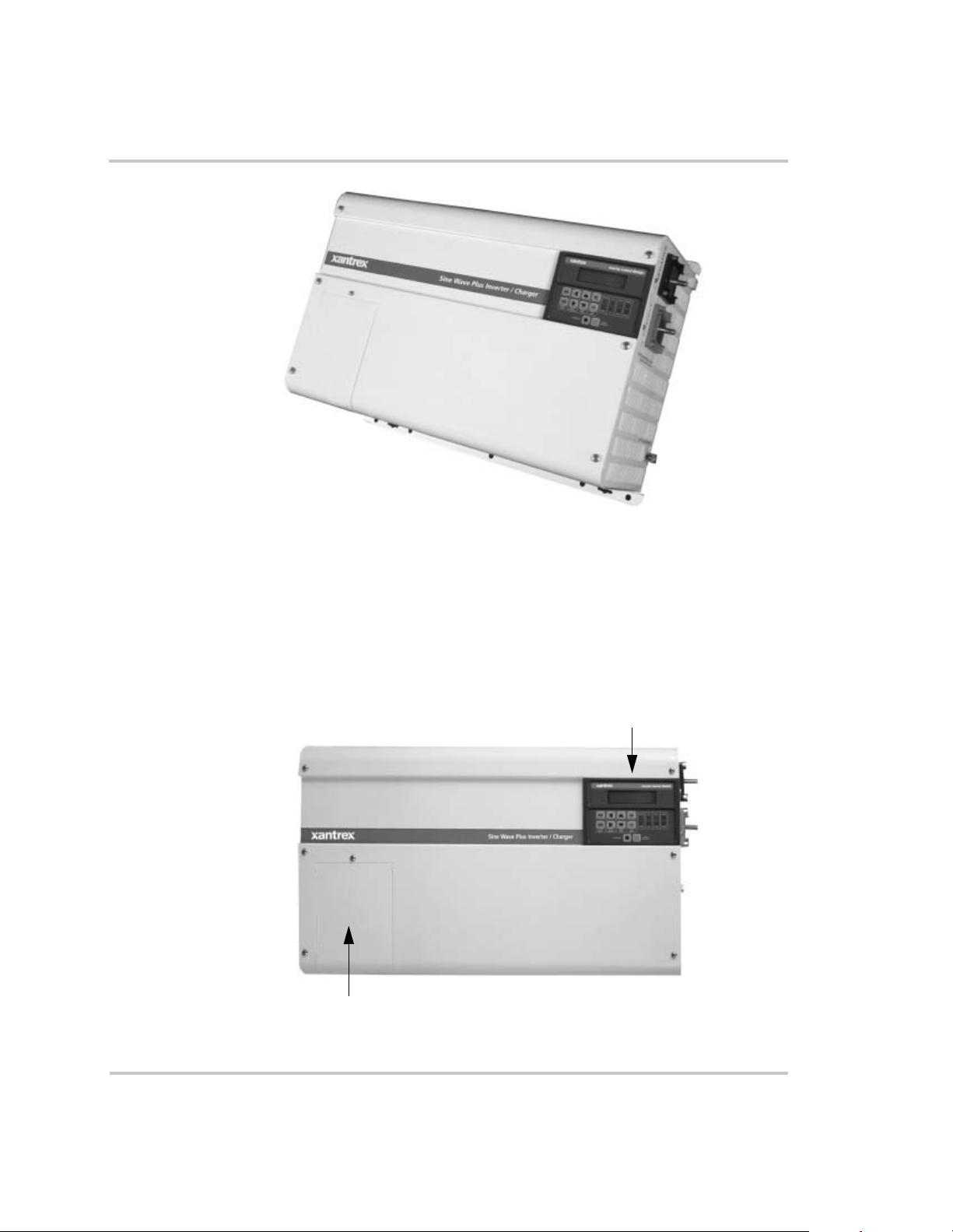
Figure 1-1
The Sine Wave Plus
The front of the Sine Wave Plus has the following features:
• the Inverter Control Module (ICM) Display
• the AC Access Cover
Inverter Control Module Display
AC Access Cover
Figure 1-2
976-0043-01-02 1–3
The Front Side of the Sine Wave Plus
Introduction
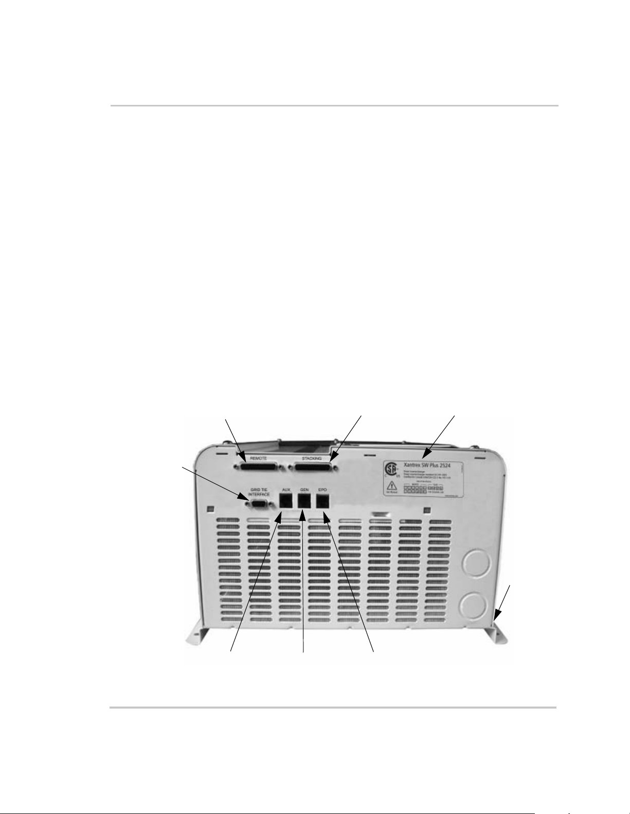
AC Side
The AC side of the Sine Wave Plus has the following features:
• The Remote Monitor Port for connecti ng a remote Inverter Control
Module (ICM) or the Inverter C ommunications Adapter (ICA)
• The Stacking Port for connecting two Sine W ave Plus inverters
• The AUX Port for connecting the Auxiliary Load Module (ALM)
• The GEN Port for connecting the Generator Start Module (GSM)
• The EPO Port for connecting an Emerge ncy Power Off (EPO) switch
• Certification Label
• The Grid Tie Interfa ce Port . Th e G rid Tie featur e is curren t ly not
available with the Sine Wave Plus models. However, the port has
been included in the even t tha t the feat ure can b e enab l ed wit h an
upgrade at a future date. Continue to check our website
www .xantrex.com for more inform at ion and future enhancements on
the Sine Wave Plus Inverter/Charger.
• The Serial Number Stick er is on the rail as shows in Figure 1-3.
Grid Tie
Interface
Port
(not used)
Figure 1-3
Remote Monitor Port
AUX Port
GEN Port EPO Port
The AC side of the Sine Wave Plus
Stacking Port
Certification Label
Serial
Number
Sticker
1–4 976-0043-01-02

Emergency Power Off (EPO) Option
The Sine Wave Plus offers an Emergency Power Off (EPO) option
through the use of the EPO Port. The EPO feature is designed to shut
down the inverter from a remote location (or switch).
Since the type of the switch will be dependent on the installation, EPO
switches are not provided with the Sine Wave Plus. However, many
commonly availabl e emergency shut off switches will work with the Sine
Wave Plus EPO. Consult your local system designer or qualified
technician for assistance.
The EPO is connected to the Sine Wave Plus with a telephone cord
(RJ11type connector) to the dedicated EPO port on the AC (left ) side of
the inverter.
See Appendix G, “Emergency Power Off Switches” for additional
information about this f eature and how to prepare a cable for it.
Certification Label
The Sine Wave Plus has been tested to nationally r ecognized safety
standards and has been found to be free from reasonably foreseeable risk
of fire, electric shock, and related hazards when installe d and operate d in
accordance with all the instructions provided in this manual and in
accordance with all applicable local and national codes.
Basic Features
Please refer to the Certification Label affixed to the AC side of the
inverter for specific agency information.
See Figure 1-3, “The AC side of the Sine Wave Plus” on page 1–4 for the
location of this information.
Model Number
Certification
Statement
Date of
Manufacture
Figure 1-4
976-0043-01-02 1–5
Certification Label

Introduction
DC Side
The DC side of the Sine Wave Plus has the following features:
• the positive (+) battery terminal
• the negative (–) battery terminal
• the battery temperature sensor port
• the chassis ground lug
Chassis
Ground
Lug
Figure 1-5
Positive (+)
Battery Terminal
The DC side of the Sine Wave Plus
Negati ve (–)
Battery Termin al
Battery
Temperature
Sensor
1–6 976-0043-01-02

Battery Temperature Sensor (BTS)
A BTS is provide d with each Sine Wave Plus Inverter/Charger. This
sensor can easily be installed in the system to ensure proper charging of
the batteries based on tempe ratur e. Installing a BTS extends battery life
by preventing overchar ging in warm temperatures and undercharging in
cold temperatures .
If more tha n one BTS is being used, install them adjacent to each other so
that they all detect a common temperature.
Basic Features
Figure 1-6
Battery Temperature Sensor (BTS)
See Table C-4, “Variances in Charging Voltage based on Battery
T emperature” on page C–14 and Table C-5, “Temperature Compensation
Calculation” on page C–14 for additional information.
976-0043-01-02 1–7

Introduction
Top
The top of the unit has the following featur e s:
• Circuit Breaker - This circuit breaker protects the unit’s internal
wiring while the unit is inverte r or charging. It is not used for the
pass-through curr ent. This is not a branch-circuit rated bre aker.
Separate output breake rs are still required. If the button is protruding
from the chassis as shown in Figure 1-7, it means the circuit breaker
has tripped open. Press the break er back in to reset it.
• Warnings Label
• Ratings Label
Top View of Sine Wave Plus Inverter/charger
Circuit Breaker
AC End
Warnings Label
Circuit Breaker Open Circuit Breaker Reset
Ratings Label
DC End
Figure 1-7
1–8 976-0043-01-02
External Output Circuit Breaker

2
System Configuration
Chapter 2, “System Configuration” contains informat ion to
help you plan for a Sine Wave Plus installation in an off-grid,
on-grid, or backup power application.

System Configuration
Pre-Configuration Planning
Importance Pre-configura tion planning is essential to ensure opti mal performance for
your system. This section outlines the components of a system and how
you can plan for them.
Types of Applications
The Sine Wave Plus Inverter/Charger can be configured for the following
applications:
• OFF-GRID (stand-alone) app lications where no utility power is
available.
See Figure 2-17 through Figure 2-20 for illustrations of off-grid
applications.
• ON-GRID applications where it can ope rate the AC loads when the
Utility System (grid) fails, ke ep the batter ies charge d, and/ or function
as an energy management cont roller .
See Figure 2-21 and Figure 2-22 for illustrations of on-grid
applications.
Important: Be sure to consult with your local utility company and/or permit
office to ensure that the desired configuration will be code-compliant. Be sure to
obtain the proper licenses and permits as required by law.
Important: Installatio ns of this equipment s hould only be performed by skille d
personnel such as qualified electricians and Certi f ied Renewable Ener gy (RE)
System Installers. For a list of Xantrex Certified RE dealers, ple ase visit our
website at www.XantrexREdealers.com.
System Considerations
You need to consider the following issues as you design your system.
System output How much power will be required and how it will be produced:
❐ Single or dual inverters (based on output voltage and output
watts required)
❐ Output watts required (i.e., continuous capacity and surge capacity)
❐ Output voltage (120 Vac or 240 Vac)
See “System Output Requirements” on page 2–4 fo r more information.
System input What are the sources of power for your system:
❐ Utility power
❐ AC generator (See “Generator Considerations” on page 2–19)
2–2 976-0043-01-02

Pre-Configuration Planning
❐ Renewable energy systems (e.g., PV arrays, wind turbines etc.)
See “System Input Requirements” on page 2–4 for more information.
Location What are the safe, physical environmental requirements for your
installation:
❐ Mounting location for optimal performance and easy access of all
components
❐ Ventilation and clearance requirements for all components
❐ Mounting method (wall or shelf)
❐ Additional items/mater ials required for mounting
❐ RFI or EMI considerations
See “Location Considerations” on page 2–5 for additional information.
Grounding What methods of protecti on and grounding are required:
❐ Grounding type (i.e., ground bar, gr ound bus, or ground rod)
❐ Neutral-to-ground bonding requirements
❐ Lightning and surge prote ction
See “Grounding Considerations” on page 2–7 for additional information.
Battery What kind of DC storage will be used:
❐ Battery type and size
❐ Battery cables and sizes
❐ Size of the battery bank and it’s configuration
❐ Location of battery bank to rest of system
See “Battery Considerations” on page 2–11 for additional information.
Wiring What is needed/require d for the AC and DC wiring for this installation:
❐ Types and sizes of wires needed
❐ Types and sizes of conduits needed
❐ Types and sizes of fuses, disconnects and/or circuit breakers
❐ Additional equipment for code complia nce (e.g., service panels,
conduit boxes, emergency shutoff switches e tc.)
❐ Wire routing
See “Wiring Considerations” on page 2–18 for additional information.
976-0043-01-02 2–3

System Configuration
Generato r Will a generator be used:
❐ Voltage Output Requirements
(120 Vac only, 120/240 Vac, or 240 Vac only)
❐ Auto-Start or Manual-Start
Important: Auto-start generators require the addition of the GSM to enable
the inverter to control the operati on of the generator.
See “Generator Considerations” on page 2–19 for additional information.
Additional equipment
What additional equipment is needed:
❐ Remote mo ni tor s, interface cables, stack in g cable s , DC ch arge
controllers, a uxiliary load controllers, T240 autotransformers etc.
See “Additional/Optional Equipm ent Considerations” on page 2–22 for
additional infor mation.
System Output Requirements
Determination Dete rmine the inverter output size requirements by calculating the
maximum, continuous capacity and surge (inrush current) capacity the
system will demand.
• Add all potential loads which would be on at once to determi ne
continuous power requir ements.
• Add the surge current of all loads whic h might start at once to
determine surge requirements (e.g., washer spinner, waterpump and
refrigerator compressor could a ll start at once).
More information See Appendix C, “Understanding Amp-hour Requirements” for
assistance in determ ining the System Output Requirements.
System Input Requirements
Determination Determine the input r equirements based on the output requirements. In
other words, is grid power available or will renewable energy equipment
be used? Wil l a gener ator be used to supple ment or back up the othe r input
sources?
More information See “Generator Considerations” on page 2–19 and Appendix D,
“Generators” for additional information regarding using generators for
system input.
2–4 976-0043-01-02

Pre-Configuration Planning
Location Considerations
Dry Inverters contain sophisticated electronic components and should be
located in a well-prote cted, dry environment away from sources of
fluctuating or extr eme temper atures and moisture.
The better the environment, the longer the inverter will last. Consider
installing your inverter in the same type of location in which you would
store high quality electronic equipment of equal value.
Avoid saltwater Exposure to saltwater is particularly destructive and potentially
hazardous. Internal corrosi on caused by improper inst allat ion may cause
the inverter to prematur ely fail and additionally will void the warranty.
Close to battery bank
Locate the inverter as close to the batteries as possible in order to keep the
battery cable length shor t. However, note the following warnings and
important notes about inve rter location.
WARNING: Explosion and Corrosion Hazard
Do not loca te the i nve rte r di rec tly above the bat ter ies or i n th e sa me com par tmen t
as vented batteries.
Vented batteries generate hydrogen and oxygen, which if accumulated, can be
ignited by an arc caused by connecting the battery c ables or switching a relay.
Vented batteries also gene rate hydrogen-sulfid e gas, which is corrosive to
electroni c equi pment.
Batteries can sometimes re lease explosive ga s, please see the battery
manufacturer’s recommendations for ventilation r equirements.
CAUTION: Damage to Inverter
Do not mount the inverter in the same space as the generator. The heat and dust
from the generator can damage the inverter.
RFI Interference Inverters can generate radio frequenc y interference (RFI) . Loc ate any
sensitive electronic equipment susceptible to RFI as far away from the
inverter as possible . This inc ludes radios and televisions.
Electromagnetic Interference
Inverters can emit strong electromagnetic f ields. This should be
considered when choosing an installation location.
See “FCC In fo rm at ion to t he User ” on page viii for additional
information regar ding RFI requirements.
976-0043-01-02 2–5

System Configuration
Fire Safety All Sine Wave Plus inverter/chargers meet UL fire safety standards as
outlined in UL 1741. As such, in the eve nt of a fail ure, th e Sine Wave Plus
is designed to fail safe. Be sure the spe cific mounting and ventilation
requirements outlined in this Owner’s Manual are followed carefully.
Do not locate the inverter near readily flammable materials such as cloth,
paper, straw, plastic etc. Flammable materials should be kept a minimum
distance of 24 inches (60 cm.) from the top surface (when wall mounted)
and 12 inches (27 cm.) from either side surface and the front of the Sine
Wave Plus. Readily flammable materials refers to instantly combustible
substances such as cloth, paper, straw, an d plast ic sheeting.
Mounting Considerations
Method The inverter can be mounted on a ve rtical surface (or wall) or on a shelf.
The advantage of the wall mounting is to provi de easier acces s to the
controls and displays.
Securing The mounting surf ace (wall or shelf) must be capable of suppor ting twice
the weight of the inverter. The keyhole slots should not be used as the
only method of securing the unit to the mounting surface. Use all ten
mounting holes and all four ke yhole slots for securing the unit and use
0.25-inch diameter bolts for mounting.
Ventilation Requirements
Location Install the inverter in a well-ventilated area/enclosure for proper
operation. The inverter’s thermal shutdown point will be reached sooner
than normal in a poorly ventilated environment re sulting in reduced peakpower output and surge capa bility as well as shorter inverter lif e.
Requirements Provide a minimum clearance of 6 inches (12 inche s is pref erred) around
the top and 6 inches a t t he AC- and DC -side of the i nve rter for venti lation.
A fan-forced, fresh-air vent (on the inverter’s AC side) allows cool air to
enter the unit and exit from the DC-end of the inve rter . Ensur e that this
vent is not obstructed with for eign objects, such as dirt and dust and that
the minimu m clearances are met.
Airflow clearance All air ventilatio n openings should have 6 inches of clearance and there
should be no nearby cover over the top of the unit. This is to preve nt
warm, exhausted air from the unit from being drawn back into it. The
warm air could cause premature shutdown due to overhe ating.
Screening The unit is equipped with screening to pr ev ent insects and rodents from
entering. This screening needs to be checked and cleaned regularly from
the outside to prevent dust buildup.
2–6 976-0043-01-02

Pre-Configuration Planning
Grounding Considerations
Types Whether you are installing a new system or integrating new parts into an
existing system, the four types of grounding to consider are:
• DC system grounding
• Inverter groundin g
• Chassis grounding
• Bonding the grounding system
Important:
All install ations must comply with nat ional and local codes and ordinances.
Consult local and/or national codes and the NEC/CEC for specific grounding a nd
bonding require ments for the desired installation.
DC System Grounding
Systems The Sine Wave Plus can be used in either a positive or negative grounde d
system. However, unless you are installing the inverter into an existing
positive gro unded system (i.e., a telecommunicat ions system), it is highly
recommended to use negative grounding.
Positive grou nd In a positive ground, the positive conductor from the battery bank is bonded to earth ground. This arrangement is most often used in telecommunications systems where an isolated ground is a requirement.
The grounding requirements vary by country and by application.
Negative ground In a negative ground, the nega tive c onductor f rom the battery bank is bond ed to earth ground. This is the most common form of grounding methods used for residenti al and commerc ial applic ations. The
Sine Wave Plus meets FCC part 15 Class B regulations in a negative
grounded system. See “FCC Information to the User” on page viii for
additional infor mation.
Convention The remainder of this guide will ass ume the negative ground convention.
Important:
applicati ons) to ground can only be in one location in the DC system. This DC
ground bond must be made in a non-serviceable item in the DC system. The
Xantrex DC175 a nd DC250 can have the optional DC Bonding Block (DCBB)
installed to provide the DC system bond. Additionally, the Xant rex PVGFP can
also provide this bond a nd comply with NEC/CEC requirements for roof
mounted PV arrays installed on dwelling units (homes).
976-0043-01-02 2–7
The bonding of the DC negative (or positive in positi ve ground

System Configuration
Inverter Grounding
WARNING: Shock Hazard
Attach the ground lead BEFORE atta ching any AC or DC power connections.
Requirement The inverter/charger should be connected to a grounded, permanent
wiring system with the AC and DC grounds commonly bonded to each
other and should be bonded to the grounding syste m at only one point in
the system. See “Bonding the Grounding System” on page 2–10 for
additional infor mation.
Conductor size The size for the grounding conductor is usually based on the size of the
circuit breaker in the DC system. Table 2-1 provides battery DC
disconnect sizes and minimu m wire sizes of copper ground wires for
grounding systems.
It is recommended that the size and gauge of grounding wire should be
more than the NEC/CEC minimum requirements when inst alling power
sources such as inverter/chargers or generators.
Table 2-1
Recommended Minimum Safety Ground Wire and
DC Disconnect Sizes per NEC
Battery DC
Disconnect Size
30 amp or 60 amp #10 AWG
100 amp #8 AWG
200 amp #6 AWG
300+ amp #2 AWG or greater
Minimum Size of Copper
Ground Wire
Note: Field experience has demonstrated that long distances or high
impedance grounds can cause equipment malfunc tion or damage.
WARNING: Explosion Hazard
Never use a gas pipe or gas line for grounding purposes. The inverte r is a power
source and it is int ended to be grounded at the service/main ground rod.
2–8 976-0043-01-02

Pre-Configuration Planning
Equipment or Chassis Grounding
WARNING: Shock Hazard
Attach the ground lead BEFORE attaching AC or DC power conne ctions.
Equipment or chassis groundi ng connects the metallic chassis of the
various enclosure s together to have them at the same voltage potential,
thus reducing the possibility for electric shock. It also provide s a path for
fault currents to flow thr ough to blow fuses or trip circuit breakers. The
size of the connecting conductors should be coordinated with the size of
the over- current de vices i nvolve d. Und er some circ umstan ces, t he c onduit
and enclosures themselves will provide the current paths.
Grounding Electrodes/Ground Rods
Purpose The purpose of the grounding electrode (often called a ground rod) is to
maintain the potentia l of equipment tie to it at “ground” pote nti al to avoid
a shock hazard. It also shunts to ground fault currents and currents due to
ground tied filtering.
Size The size for the conductor to the grounding electr ode or grounding system
is usually based on the size of the largest conductor in the system. Most
systems use a copper- plated rod as the grounding electrode. The rod
should be 5/8 inch (16 mm) round by 8 feet (2 meters) long and driven
into th e ear t h. It i s also common to us e co p per wi r e pla ce d i n t he co n cr et e
foundation of the building as a grounding system. Either method may be
acceptable, but the local code will prevail. Connection to the ground
electrode shoul d be done wi th specia l cla mps loca ted above ground where
they can be periodicall y inspected.
Note:
system, are subject to severe damage from the effects of lightning. Lightning
damage is not covered by your warranty. If your installation is in an area of
high probability for lightning, you should consult with a local lightning expert
or your a uthorized Xantrex install er to determi ne what extra precautions should
be taken to protect your equipment.
This inverter, along with all other power electronic devices in your
Number of rods Many large systems use multiple ground rods. The most common
example is providing a direct pa th from the solar array to earth near the
location of the solar array. Most electrical codes ex pect mul tip le gr o und
rods to be connected by a se para te wire with its own set of clamps. If this
connection is done, it is a good idea to make the connection with a bare
wire located outside of the conduit (if used) in a trench. The run of buried
976-0043-01-02 2–9

System Configuration
wire may be a better grounding electrode than the ground rods. Well
casings and water pipes can also be used as grounding electrodes. Unde r
no circumstance should a gas pipe or line be used.
Important:
Consult local codes and the NEC/CEC for more information.
Bonding the Grounding System
Definition Bonding means connecting one of the curre nt- carrying conductors
(usually the AC neutral and DC nega tive) to the gr ounding system. When
the other ungrounded conductor (the hot or positive) touches the
grounding system, current will flow through it to the point of connection
to the grounded conductor and back to the source. This will cause the
over-current protection to stop the flow of current, protecting the system.
This point of connect ion between the grounding system (ground rod), the
current carrying grounded conductor (AC neutral and DC negative), and
the equipment grounding conductor (green ground wire, equipment
ground) is called a “bond”.
Bonding locations Bonding is usually located in the over-current protection device
enclosures (both AC and DC). Residential systems In residentia l systems bonding is located at the
utility panel, after the power has gone through the kilowatt-hour meter of
the utility (if prese nt).
Renewabl e en erg y sys te m s Renewable energy system s, with no gr id connection, can be grounded at the main AC distribution panel. Renewable energy systems should be grounded to the same grounding electrode as the AC distribution panel.
Bonding should not be done at the inverte r. Codes do not generally allow
it because the inverter is considered a “serviceable” item that may be
removed from the sytem, in which case, the bonding would be broke n.
Bonding at one point
Bonding must be done at only one point in an electric al system.
Inherently, Xantrex systems have two separate electric systems; a DC
system and an AC system. This means t hat two bonding points will occur
in all inverter appli cations. The bonding point will also be connecte d to
the equipment (chassis) grounding conductors. It is common to have two
separate conductor s connect the ground electrode and the two bonding
points. Each conductor should use a separate clamp.
Guidelines The ground and neutral must be bonded at one place, and only one
place, in the system. Use the following guideline s for ground and neutral
bonding:
2–10 976-0043-01-02

Pre-Configuration Planning
Generator If the generator is the main source of power, (that is, no utility grid power) then the neutral and ground connections are bonded at the main AC distribution panel.
Utility grid If the utili ty grid is t he mai n source of powe r , the n the bond should be at the utility AC distribution panel.
No utility or generator If there is no utility or generator in the system, then the ground/neutra l bond should be in the inverter AC distribution panel.
Battery Considerations
CAUTION: Damage to Equipment
The Sine W ave Plus is intended to operate with batteries as its source of DC
power. Do not connect DC chargi ng sou rces , such a s PV arrays, win d turbine s, or
micro-hydro turbines, direct ly to the Sine Wave P lus . If DC chargi ng s ources are
connected dire ctly to the inverter, the DC rating of the inverter can be exceeded
and the inverter can be damaged.
Accessibility Locate the batteries in an accessible loca tion if maintenance is required.
Two feet clearance above the batteries is recommended for access to the
battery caps. They should be located as close to the inverter as possible
without limiting access to the inverter’s disconne cts. Install the batterie s
to the right of a wall-mounted inver te r for easy access to the DC side of
the inverter and shorte r cable runs. The battery bank may also be placed
on the opposite side of the wall on which the inver ter is mounted.
Vented enclosures For safety and to limit access to the batteries, the batteries should be
housed in an enclosure or dedicat ed room that can be locked or screened,
and ventilated. It should be vented to the outside by a 1-inch minimum
vent pipe located at the top of the enclosur e . An inta ke vent should be
installed at the bott om of the enclosure to promote air circulation.
Important: These vents exhaust corrosive and explosive hydrogen sulfide
gases and must not be overlooked when designing an enclosure.
Enclosure requirements
976-0043-01-02 2–11
The enclosure should be made of an acid resistant material or have a
finish that resist s acid to prevent corrosion and must be capable of
containing the elect rolyte from at least one battery should a leak occur.
Enclosures located outside must be rainproof and screened to prevent
access by rodents or insects and insulated from extreme temperatures.
Batteries will give their best performance and servic e life when operat ing
in a 20 to 25 °C ( 6 8 t o 77° F) envir o nment .

System Configuration
More information Consult your battery vendor f or additional information on battery
enclosure requirements.
Battery Bank Requirements
Determining requirements
Note:
battery bank is 100 Ah. T he rec om me nded battery bank size is determined by
the battery ba nk works h ee t in Appendix C (Table C-1, “Determining Average
Daily Load in Amp-hours” on page C–7). The inverter is designed to operate
with batterie s and should not be operated wit hout them.
Based on the peak current of the inverter, the minimum allowed
To determine your battery requirements you need to know what type of
batteries to use, the number of batt eries for the battery bank, and how to
configure the bank to optimize voltage output according to system
requirements.
See Appendix C, “Battery Information” for additional information on
determining batte ry bank type and configuration.
The DC voltage of your inverter must match the DC voltage of your
system and all of its accessori es . If you hav e a 24-volt inverter , the n the
battery bank and all other DC devices in the system must be configured
for 24 volts.
WARNING: Fire Hazard
Undersized cables ca n overheat and melt, creating a fire hazard when subjected
to heavy (peak) loads. Always us e a cable of proper s ize and length, rated for the
amperage of the inverter and batteries.
Battery Cable Requirements
Important:
connections. Do not use coarse, strand ed wire, as the lack of flexibility may
damage battery and inverter terminals.
Size and length Battery cables must be the correct size and length to optimize
performance and ensure the safety of the system. Larger diameter cables
(smaller AWG number) have less voltage drop and are, therefore, more
efficient when tr ans ferr ing power to and from the batte ri es. Th e use o f
oversized cables ( e. g., 4/0 cables) will allow you to ta ke advantage of the
improved surge perf ormance of the Sine W ave Plus inverters.
2–12 976-0043-01-02
Use only fine, stranded copper cables for battery and inverter DC

Important
D
recommendation
Pre-Configuration Planning
Follow the battery cable recommendations listed in this guide. It is
absolutely imperat ive that you adhere to the battery cable size (wire
gauge) and length recommendation s prov ided in this sec tion. I f cables are
used that are too long or of insuff icient gauge (i.e., the diameter is too
small), then inverter performance will be adversely af f ected.
In addition to poor inverte r perfor mance, undersized cables can result in
fire caused by overheating wir es. Any damage to the inverter caused by
overheating from undersized wire is not covered by the Xantrex war ranty.
Important:
Figure 2-1 is for reference only. Sizes shown are for the
conductor. Do not include any insulation, or shea thing, when determining your
wire size. Due to prin ting anomalies, these dimensions may not be to scale.
Size
iameter
Size
Diameter
Size
Diameter
12
14
.07210.1158.1466.184
.073
1
.335
250 MCM
.580
1/0
.380
300 MCM
.635
2/0
.420
350 MCM
.690
4
.235
3/0
.475
400 MCM
.730
3
.281
2
.295
4/0
.530
500 MCM
.820
Figure 2-1
AWG Wire Size Reference Chart
Battery cable length Cable length is another important factor. Runs should be kept as short as
practical. Longer cable runs increase resistance, thus lowering the overall
efficiency of the system. This is especially true in lower voltage systems
where, depending upon the length of the cable run, it may be necess ary to
oversize the diameter of the wire, or pa rallel (double) the cables. Table 2-
2 provides recommended minimum cable sizes for various cable lengths
976-0043-01-02 2–13

System Configuration
and inverter amperage per NEC/CEC guidelines. It is recommended that
the cable has battery acid resistant insulation and is rated for 90 °C
(32 °F) or better.
Be sure to check with any local regulatory agencies for additional
requirements.
Battery cable lugs Battery cabl es must have crimped copper compression lugs or crimped
and soldered copper compression lugs. Soldered connections alone are
not acceptab le.
High quality ba ttery c able s are ava ilable f rom Xantrex i n an assor tment of
lengths from 1½ to 10 feet in #2/0 AWG and from 1½ to 15 feet in
#4/0 AWG sizes. These c ables are color-coded with pressure crimped,
sealed ring term ina ls.
Overcurrent protection
For safety and compliance with regulations, battery overcurrent
protection is required. Fuses and disconnects must be siz ed to protect the
wiring in the system and are required to open before the wire reaches its
maximum current carrying capability.
Table 2-2
Inverter
Model
2524 134 167 #2/0 A W G
2548 67 84 #2/0 AWG
4024 214 267 #4/0 A W G
4048 107 134 #2/0 A W G
5548 147 184 #4/0 A W G
Recommendced Battery Cable Size Versus Length
Maximum
Continuous
DC amps
a. “Maximum Conti nuou s DC amps ”, as show n in th is table , is bas ed o n low
battery vo ltage with an efficiency of 85%.
b. “NEC amps”, as shown in this table, is based on low battery voltage, and
efficiency of 85%, and a 125 % NEC de rating.
NEC
a
amps
Up to 5 Feet
b
One-way
(67.4 mm
(67.4 mm
(107 mm
(67.4 mm
(107 mm
2
)
2
)
2
)
2
)
2
)
Up to 10 Feet
One-way
#4/0 AWG
(107 mm2)
#4/0 AWG
(107 mm2)
#4/0 AWG x 2
(107 mm2 x 2)
#4/0 AWG
(107 mm2)
#4/0 AWG x 2
(107 mm2 x 2)
Up to 15 Feet
One-way
Not
Recommended
#4/0 AWG x 2
(107 mm2 x 2)
Not
Recommended
Not
Recommended
Not
Recommended
Xantrex DC175 and DC250
The NEC/CEC requires both overcurre nt protection and a disconnect
switch for resi den tia l and commercial electr ic al sys te ms. Th es e item s are
not supplied as part of the invert er. However, Xantrex offers a DC circuit
breaker disconnect module specifically designed for use with Xantrex
2–14 976-0043-01-02

Pre-Configuration Planning
inverters to meet NEC/CEC compliance. Two amperage ratings are
available: a DC250 (250 a mps) and a DC175 (175 amps) in either singleor double-pole config urations for single or dual inverter installations.
See “DC Disconnect Boxes (DC175/DC250)” on page 2–24 for
additional infor mation on the Xantrex DC175 and DC250.
After selecti ng battery cables based on the distance from t he battery bank
to the inverter, add battery overcurrent protect ion in t he battery c able l ine,
based on Table 2-3. This table will help you to determine your maximum
breaker/fuse siz e base d on the cable size you selected previously.
Table 2-3
Cable Size Required
#2/0 (00) AWG 175 Amps 175 Amps 265 Amps
#4/0 (0000) AWG 250 Amps 250 Amps 360 Amps
Battery Cable to Maximum Breaker/Fuse Size
Maximum
Rating in
Conduit
a. The term “free air” is defined by the NEC/CEC as cabling that is not
enclosed in a conduit or a raceway. Cables enclosed in conduit or
raceways ha ve subs tantial ly lower co ntin uous curre nt carr ying abil ity du e
to heating factors.
b. The NEC/CEC allows rounding to the next highest standard fuse size
from the cable rating (i.e., 150 amp cable size rounds up to a standard
175 am p size).
Breaker/Fuse
Size
Rating in
“Free Air”
Maximum
Breaker/Fuse
a
Size
300 Amps
400 Amps
Fuse Block (TFB) Some installations may not require condu it(s) or a disconnect device,
however, overcurrent protection is still required. Xantrex offers a fuse
block (TFBxxx) providing the cod e-required inverter overcu rre nt
protection for these applications. These fuses are available in 110, 200,
300 and 400 amp sizes.
Important: From this point on in this guide, any reference made to a “DC
disconnect” means either a DC breaker or a fuse with a disco nnect switch, which
will depend on your specific type of installation.
b
b
Battery Requirements for Dual Inverter Systems
The success of “stacked” or “dual” inverter systems is dependent on the
quality and maintenance of the DC connections. Stacked inverter se ts are
far less forgi ving to long, undersized, uneven, and/or poor connections
than are single inverte rs.
Dual inverters (not stacked)
976-0043-01-02 2–15
Dual inverter configurations can be used without using the stacking
interface cabl e. In this conf igura tion, two inv erter s separate ly run isol ated
loads from the same battery bank or individual battery ba nks.

System Configuration
Series stacked When inverters are “s ta cked ” t hey mu st ope rate fro m a com mo n b at tery
bank. In other words, the DC negative of one inverter must be common
with the second inverter and likewise for the DC positive.
For example:
If you have eight 6-volt batteries in a 24-volt configuration, they
would be arranged in two rows of four batteries (see Appendix C for
diagrams of various arrangements).
The negative e nds of the two “strings” of batteries must be jumpered
together to become common with each other.
Likewise, the positive ends of the two “strings” must also be
jumpere d together so that they are also common with each other.
Shunts near the inverter
Losses from the cables will cause each inverter to measure slight
differenc es in actu al voltage s, in spite of hav ing the batte ry bank common
to both inver ters. I t is e asy t o have the DC negative s common c loser to the
inverters if an in-line mete ring shunt is installed near the invert ers before
the negative cables att ach to the negative battery terminal.
Jumpers The use of optional bonding jumpers can improve how each inverter
measures the DC voltage. These measurements are used to determine
when charging amperage s should be reduced as the batteries become
charged. The bonding jumpers allow the inverte r s to agree better on what
the voltage actuall y is. The longer the DC cables are, the more likely you
will need bonding jumpers.
Shunts near the batteries
If a shunt is installed closer to the battery bank than the inverters, a
bonding jumper should be in stalled from one inverter’ s negative terminal
to the other inverter’s negative terminal. By using a negative bonding
jumper and/or a metering shunt near the inve rters, the inverters will have
a better zero volt (DC negative) reference to measure the DC voltage.
DC disconnects The DC positive is more dif ficult due to the need to ha ve DC disconnects
in each cable for the inverters. The primary reason for the DC disconnects
is for overcurrent protection for the cable it is installe d in. By usin g a
positive bonding jumper the inverters will have a more accurate DC
positive referenc e to measure the DC voltage.
Bonding Jumpers A bonding jumper may be installed from one inverter’s positive terminal
to the other inverter’s positive if a warning is placed near the DC
disconnects. This means that either DC disconnect can energize both
inverters whil e the othe r DC di sconnect is not ye t turne d on. This is ca lled
“backfeeding” a disconnect or circuit breaker. The 2002 NEC,
Section 404.6, C, Exception, allows switches to be backfed if a warning
such as the follo wing is permanently ma rked on or ad ja cent to the
2–16 976-0043-01-02

Pre-Configuration Planning
disconnect switc hes. A sample of this warning label is provided in Figure
2-2. These labels are not available or provided by Xantrex, but may be
available from your local electrical warehouse.
DC disconnects and overcurrent devic es
WARNING: Shock Hazard
Load side terminals may
be energized by
backfeed.
Figure 2-2
Sample Warning Sticker for Backfeed Conditions
The size of the bonding jumper must be the same gauge as that of the
primary battery cable in whic h the overcurrent device (DC disconnect) is
Not provided by Xantrex.
May be available a t yo ur loca l
electrical warehouse.
installed, and as always, the overcurrent device must be sized
appropriately fo r all cable s attached to it. If one overcurrent devi ce trips
then there will be only half the amount of current available for both
inverters to run f rom. If you want to run only one inverter while the othe r
is shut down (for example, for maintenance procedures), the positive
bonding jumper must be removed or there must be an appropriatel y sized
switch installed in the bonding jumper .
Battery Temperature
Cold temperatures Cold temperatures dras tically reduce battery capacity and performance.
Therefore, the batte ry enclosure shoul d provide a fairly st able temperature
for the batter ies. If batter ies are in sta lled in a cold environment, insul ation
should be installed to protect the batteries from the cold. The insulation
will act as a barrier to the cold an d also keep s the heat ge nerat ed by th e
batteries inside the enclosure providing a more stable temperature and
better system performanc e .
Hot temperatures High battery temperatu res shor ten the life of the batteries. The battery
enclosure should not be insta lled in direct sunlight where the sun can
overheat the batteries. Locate the enclosure where it will be protected
from the sun and provide vents in the top and bottom of the enclosure to
provide air flow throughout the enclosure.
For best performance, locate the batteries where they are in a room
temperature of 20 to 25 °C (68 to 77 °F)
Battery temperature sensor
A Battery Temperature Sens or (BT S ) is pr o vided with eac h Sin e Wave
Plus. This sensor can easily be installed in the system to ensure pr oper
charging of the batterie s based on te mperat ure. I nstalli ng a sensor exte nds
battery life by prevent ing overcharging in warm temperatures and
undercharging in cold temperatures.
976-0043-01-02 2–17

System Configuration
See “Installing the Battery Temperature Sensor (BTS)” on page 3–18 for
instructions on installing the Battery Temperature Sensor.
Wiring Considerations
Important:
grounding and bonding requirements specific to the intended system. All wiring
and installation methods should conform to applicable ele ctrical codes and
building co des .
Be sure to consult the local and national electrical codes to confirm
Conduit boxes For maxim um safety an d, in s ome cas es, for code- compli ance, run the AC
and DC cables in conduit(s) . Pre -plan the wire and conduit runs carefully
before installing a ny components.
Main AC distribution pan el (utility fed)
The AC1 input to the inverter requir es a 60-amp breake r maximum be
installed into the main AC distribution panel (double-pol ed if stacked) to
protect the wiring in accordance with NEC. This breaker supplies utility
grid power to the inverter. AC1 is not used in off-grid applications.
Generator disconnect switch
Installing a discon nect switch with an appropriately sized circuit breaker
(60 amp maximum) between the generator and inverter provides overcurrent protection f or the wiring between the generator and the inverter’s
AC2 terminal. This is also a good safety practice as it also provides a
means to prevent the inverter wiring from becoming energized in the
event that an electric-start generator starts unexpectedly while the inverter
is being serviced.
Subpanel/Inverter Panel
In on-grid applications, loa ds backed up by the inve rter will need to be
rerouted from the main AC distribution panel to a subpanel. In off-grid
application, the inverter pa nel functions as the main electrical panel.
Always use properly rated cir cuit breakers.
WARNING: Fire Hazard
Check existing structure wir ing for “mul ti- branch wiri ng”. For new cons tructi on,
do not use “multi-branch wiring”.
For both cases refer to Appendix F, “Multi-wire Branch Circuit Wi ring” for
addi ti on al info r m a tion.
Fuses and/or DC disconnects
2–18 976-0043-01-02
Install a DC disconnect brea ker or fuse in the positive, ungrounded,
battery line. This breaker protects the DC wiring in the event of an
acciden tal short. Size the brea k e r in acc o r d a n c e with t h e batt er y c a b l e s .
Switch this breaker OFF (or remove the fuse) whenever servicing the
batteries or inverte r(s).

Pre-Configuration Planning
Note: A fuse with out a s witchable disconnect alone does not mee t
NEC/CEC code.
Wire size for AC connections
A minimum of #6 AWG THHN wire is recommended for all AC wiring
(input and output).
Wiring scenarios Determine all wire r outes both to and from the inverter and which
knockouts are best suite d for connec ting the AC conduits. Possible
routing scenarios inc lude the following.
• AC and DC grounds to an external ground rod
• AC input wiring from the main service panel to the inverter/charger
(on-grid applica tions only)
• AC input wiring from the generator to the inverter/charger (if used)
• AC output wiring from the inverter /charger to the subpanel
• DC input wiring from the PV array to the controller/batteries
• DC input wiring from the batteries to the inverter/charger
• BTS cable from the batteries to the inverter/charger (ke ep separate
from battery cables)
• Remote ICM cab l e to the invert er/ charger (if used)
• Load circuit wiring rer outed from the main service panel to the
subpanel (on-grid appl ications only)
Important:
cuts in the walls. Cut holes in the walls at a ppr opriate locations for ro uting
wiring/cables.
Check for existing el ectrical wiring or plumbing prior to making
Generator Considerations
Important: The information co ntained in this guide is basi c wiring
information whic h can aid the genera tor manufacturer or electrician in assisting
with your installation. Xantrex is not responsible for providing deta iled tech nical
support or wiring instructions for generator operation.
Purpose An engine generator can be used as follows:
• as an input power sou rce instea d of (or in conjunc tion with) the util ity
power
• as a backup power source (connected with additional hardware) to
automatically power the loads when utility is not present (utility
outage)
• as a means to charge the batteries.
976-0043-01-02 2–19

System Configuration
Stable Voltage The generator should provide a stable voltage and frequency output for
the inverter to synchroniz e with.
AC wind turbines and small scale AC water turbines are not
recommended for use as AC power sources as they may not be able to
provide a stable volta ge and frequency as loads and charger requirements
change. The only w ay to pr acti cal ly use sources such as these is to tak e
the AC power and rectify it into DC. Be sure to include a diversion type
controller (e.g., Xantrex C-Series) to protect the batteries from
overcharging.
Types of Generators
There are AC generators and DC generators.
AC Generators AC generators can power AC loa ds and charge batteries. An AC
generator is bett er suited for resident ial appl ications, since th e majority of
loads require AC power.
DC Generators DC generators can power DC loa ds and charge batteries. In a r esidential
application, DC generators are primarily used to charge the batteries.
Output Requirements
An AC generator can output 120 Vac only, 120 Vac and 240 Vac together,
or 240 Vac only depending on the overall needs of the system. The
generator must be large e nough to provide adequate power to charge the
batteries and support a certain amount of AC loads. I f the generator is not
large enough, the amount of time it takes the inve rter to charge the
batteries will incr ease.
A DC generator is used primarily to charge the batteries. AC loa ds are
only powered by the energy stored in the batteries. The generator must be
large enough to provide adequate power to charge the batteries.
Generator start types
Starting type s Generators can either be manually starte d, or when properly equipped,
automatically started. The Sine Wave Plus can operate well with either
kind of generator. It is recommended, however, to consult the desired
generator’ s manufacturer to ensure the generator of choice is best suited
for the desired application.
Manual-start and electric-start generators
When using a manual-start or electric-start generator, the generator is
connected to the inverter AC2 input but is not controlled by the inverter.
The starting and stopping of the generator occurs at the generator.
Manual-start genera tor s are started with a recoil-star t pull cord. Electricstart generators are started by turning an ignition/starter key, switch, or
similar means.
2–20 976-0043-01-02

Pre-Configuration Planning
Manual-start and electric-start generators typically do not have selfprotection feat ures to shut down the generator in the event of low oil
pressure, over -heating , overcranking, etc. , and, therefore , are not designed
for unattended starting and operation.
If using a manual-start or electric start generator, be sure that the
generator is located where it can be easily accessed to be started.
Auto-start generators
Starting requirements
When using an auto-start generator, the generator is connected to the
inverter AC2 input. The inverter controls the operation of the generator
with the assistance of the optional GSM. Auto-start generators are
equipped with terminals for signal wires to be routed and connected to a
remote switch/r elay (a "dry contact") to signal the generator to run and/or
stop.
Auto-start gener ators are equipped with se lf- protect ion feature s to dis able
starting and/or to shut down a generator in the event of low oil pressure,
over-heati ng, over crankin g, etc. Whe n generator s are equippe d with these
protection features, they are designed for unattended starting and
operation and may be compatible with the Sine Wave Plus with the
optional GSM.
Be sure to locate an auto-s t art g enerator in a place prot ected from
extremes of temperatur e so it can successfully start and operate without
assistance.
Important:
only function on generator s equippe d with two- or three-wi re auto-sta rt operat ion.
Most auto-start gene rators have this feature. Check with your generator suppl ier
and make sure this feature is available. Additional hardware may be required.
The automatic generator start feature of the Sine Wave Plus can
The generator can be set to start based on four different, user-specified,
scenarios w ith differe nt req u irements for each:
• battery voltage
• inverter load current
• time of day
• exercise time
If used with an application that includes utility powe r, the generator will
be started only if utility power is not available, as it is not possible to use
both generator and utili ty power at the same time (except for the
scheduled exercise time).
It is safe for both the utility an d gener ator inputs to be energized at the
same time, although the inverter can only take power from one source at
any given time.
976-0043-01-02 2–21

System Configuration
See “Generator Starting Scenarios” on page 7–23 of this guide for
specific instructions on setting the generator-start/stop conditions.
Additional/Optional Equipment Considerations
The following components are available for use with the Sine Wa ve Plus.
Some of these items may be required depending upon the intended use of
the inverter to make the instal la tion code-compliant. These components
are not provided with the invert er and must be purchased separately.
Important: Be sure to consult with your local inspe ctor and/or utility
compa n y to en su r e co mplete co mplian ce wi th lo c a l regu lations .
AC Conduit Box (ACCB)
The AC Conduit Box (ACCB) connects to the AC side of the inverte r and
accepts AC condui t runs. The AC c onduit box incl udes bypa ss/disc onnec t
breakers.
Figure 2-3
2–22 976-0043-01-02
AC Conduit Box

DC Conduit Box (DCCB)
The DC Conduit Box (DCCB) connects to the DC side of the invert er and
accepts DC conduit runs.
Additional/Optional Equipment Considerations
Figure 2-4
Figure 2-5
976-0043-01-02 2–23
DC Conduit Box
Sine Wave Plus with AC and DC Conduit Boxes Installed

System Configuration
Fuse Block
The Xantrex fuse block (TFBxxx) pro tects the power system’s DC wiring
should an overcurrent cond ition occur. The fuse block is placed between
the battery’s ungrounded conductor (usually the positive cable ) and the
DC input terminal of the inverte r.
The fuse block includes a fast acting, current limiting class-T fuse
providing extremel y fast protec tion when a short circuit oc curs. Whe n the
fuse is properly matched to the syst em curr ent, its time delay allows the
inverter to surge to f ull power without blowing the fuse. A plastic cover
prevents accidental short circuits to the fuse terminals. Fuse sizes include
110, 200, 300, and 400 amps.
There are two types of fuse blocks available. The TFBxxxC fuse block
has “set” screw lugs for cables with no termin al connector’s on the ends
(known as C-type or s tripped- end batt ery cable s). The TFBxxx f use block
has stainless steel bolt connections for cables with ring terminals (known
as ring-lugged battery cables). Both fuse blocks include a black poly
carbonate, fibe rglass reinforced base and a clear poly carbonate snap-on
cover.
Fuse Block for C-type
(stripped end) Battery Cables
(TFBxxxC)
Figure 2-6
Fuse Blocks
Fuse Block for Ring-l ugged
Battery Cabl es (TFBxxx)
DC Disconnect Boxes (DC175/DC250)
Xantrex provides two options for disconnect boxes. The DC175 and
DC250 protects your batter ies, inverter, and DC cables from damage
caused by short circuits an d overloads through use of a UL listed, high
interruption capa city circuit breaker. This breaker is designed to interrupt
the tremendous amount of power a batter y can deli ver when short
circuited. It is also de signed t o have a long e nough time de lay to allow th e
inverter to surge to full power without nuisance tripping of the breaker. If
the breaker does trip, it’s easily reset.
2–24 976-0043-01-02

Battery Status Meter (TM500A)
The TM500A features six data monitoring f unctions and three indicators
including:
• State-of-charge/amp-hour c ontent (full or percent of capacity)
• State-of- charge/voltag e (real-time voltage level, hist orical high and
low system voltage)
• Amps (real-time amps, total charging amps, total load a mps)
• Amp hours removed
• Days since fu lly ch arged
• Cumulative amp hours
• Recharge indicator
• Low-voltage indicator
• Full-charge indicator
The unit is configurable for specific system or application functions such
as setting the CHARGED indication para mete rs, battery capacity,
charging efficiency, low-battery warning conditions and a recharge
reminder. The TM500A can monitor any battery supply from
approximately 8 to 65 volts, track energy consumption, and estimate
remaining battery life.
Additional/Optional Equipment Considerations
The TM500A operates on 12-, 24-, or 48-volt bat tery systems (48-volt
systems require an optiona l shunt board).
DC250
TM500A
Figure 2-7
DC250 Disconnect Box and TM500A Battery Status Meter
976-0043-01-02 2–25

System Configuration
.
Remote Monitors
Three options are available for remote control and monitoring.
• Use a remote ICM, which is identical to the inverte r control module
display on the inverter, for distances of 25 or 50 feet (7.5 or
15 meters).
• Use a personal computer to monitor system status using an optional
ICA (for distances up to 50 feet/15 meters). The ICA can be used
with cables up to 500 feet (152.4 meters). These longer cables,
however, are not provided by Xantrex.
• Use a personal computer off-site to monitor the system using an
external modem at the inverte r site and the ICA.
Note: The ICM and the ICA use the s ame input port on the inverter. Both of
these options cannot be used at the same time.
Inverter Communications Adapter (ICA)
(for use with a personal computer
at distances up to 50 feet)
Invert e r Co n t ro l M o dule (ICM)
(for distances of 25 or 50 feet)
Note: For distances greater than
500 feet, a modem is required on sit e
Figure 2-8
Accessories for Remote Monitoring
CAUTION: Damage to Equipment
Never connect a gr ounded P C to the Remote Port if the in vert er is conf igur ed i n a
positive grou nd arrangement. Connecting a grounded PC to this port (in this
configuration) will damage both the PC and the inverter. Xantrex will not c over
damages to the PC or honor warrant y cla im s on the inverter under these
circumstances.
2–26 976-0043-01-02

Inverter Control Module (ICM)
The remote ICM allows control, monitoring, and adjustment of all
inverter sett ings from a locatio n oth er t han the I CM di splay o n the front of
the inverter. The remote ICM comes with c ables in lengths of 25 feet (7.5
meters) or 50 feet (15 meters). The remote ICM duplicates all the
functions and controls of the ICM display on the front panel of the unit.
For distanc es gre at er tha n 50 feet (15 mete rs ), see the Inverter
Communications Adapter (I CA).
Additional/Optional Equipment Considerations
Figure 2-9
Inverter Control Module
Inverter Communications Adapter (ICA)
The ICA allows the inve rter t o be con n ected dire ct l y to a PC for
monitoring and adjustmen t. The ICA comes with a 50-foot cable. The
ICA can also be used up to 500 feet away, but additional cabling will be
needed and Xantrex does not provide longer c ables at this time. It may
also be operated remotely with the addition of a modem at the inverter
site.
Figure 2-10
Inverter Communications Adapter
CAUTION: Damage to PC
Do not connect a PC to the invert er when it is configured in a posi tive ground
system. Damage t o the PC and t he inve rter may occ ur which i s not c overed und er
warranty.
976-0043-01-02 2–27

System Configuration
Generator Start Module (GSM)
The GSM is an accessory that enables the inverter to start and stop
generators equipped with a uto-start features.
Figure 2-11
See “Generator Considerations” on page 2–19, for info rm at ion on usin g
generators and Appendix D, “Generators” for additional information
regarding generator types.
Auxiliary Load Module (ALM)
The ALM is an acce sso ry that enables the inve rt er to sta rt and stop
auxiliary loads such as ala rms, water pumps, or ventilation fans.
Figure 2-12
Generator Start Module
Auxiliary Load Module
See “Auxiliary Load Module (ALM)” on page 3–42 for additional
information regar ding connecting the Auxiliary Load Module to the
inverter.
2–28 976-0043-01-02

Additional/Optional Equipment Considerations
240 Vac Application Requirements
There are two options available for creating 240 Vac output using a
120 Vac inverter:
• using an autotransfor mer to step-up or step-down the voltage, or
• stacking two identical inverters.
Autotransformer for 240 VAC Applications (T240)
The T240 allows a single inverter to increase it’s output voltage from
120 volts to 240 volts or it will take 240 Vac from a generator and “stepdown” the voltage to 120 Va c for the single inverter . For step-up and stepdown functions, two T240s will be required.
A T240 Autotransformer can optimi ze the generator output of smaller
generators (<
3.9 kW) and improves charging time.
Figure 2-13
T240 Autotransformer
Inverter Stacking Control – Series (ISC-S) Cable
The ISC-S cable is a special communications cable that allows two Sine
W ave Pl us inver ters to be conne cted tog ether in “seri es” to provide power
to both 120 Vac loads and 240 Vac loa ds.
See the ISC-S Owner’s Guide for more information on stacked inverter
applications.
Figure 2-14
976-0043-01-02 2–29
ISC-S Cable

System Configuration
Renewable Energy DC Input Sources
Renewable energ y (RE) sources (for example, photovoltaic (PV) arrays,
wind turbines, DC micro-hydro ge nerators) can be used with the inverter
to provide power for all applica tions—off grid and on grid. However, in
addition to the actual RE equipment be ing used, other items may be
needed to ensu re safety in the overall syst em , suc h as charge cont rol l ers,
diversion load controllers, and/or PV ground fault protection.
Important: Be sure to consult your authorized dealer and all local/national
electric codes to determine what additional equipment may be req uired for your
installation.
Important: Installations of this equipment should only be performed by
skilled per sonnel such as qualified electricians a nd Certified Renewable Ene rgy
(RE) System Insta llers. For a li st of Xa ntr ex Certifi ed R E dealer s, plea se visi t our
website at www.XantrexREdealers.com.
Note:
connected to either of the AC inputs on the inverter/charger. The Sine Wave
Plus cannot control or regulate DC voltages from DC sources. DC charge
controllers must be used for all DC sources such as PV arrays, wind turbines,
and water turbines.
The “charger” built into the Sine Wave Plus is only for AC power
Charge contr oller A charge controller must be used to regulate the charge supplied to the
batteries and prevents over-charging (or high ba ttery conditions). A
charge controll er prev e nts the bat te ries from ex ce ed i ng a use r-specifi e d
voltage level. This preserves and extends the life of the battery by
preventing the damage caused by over-charging. The charge controller
can also take over the functions of bulk and equalize charging.
Diversion load control
Wind turbines and hydro-electric generators may be damaged if the DC
loads are suddenly removed from them. This can hap pen if the DC
disconnect should open (tr ip) or the batteries are fully charged and no
other DC loads are connected in the syste m. A diversion load controller
prevents damage to the generator system by diverting the power from the
generator to a diversio n load devic e. This keeps a load on the generator
and controls over- spin if the batteries should be disconnected. Refer to
the controller manual for proper types of diversion load devices.
2–30 976-0043-01-02

Additional/Optional Equipment Considerations
Figure 2-15
Xantrex C-Series Charge Controllers
PVGFP The PV Ground Fault Protection (PVGFP) is designed to minimize the
possibility of a fire resulting from ground faults in a PV array (in
accordance with NEC/CEC for rooftop-mounted PV syste ms on
dwellings). It is not designed or intended to prevent electr ical shock or to
be used for PV DC ove rcu rr en t .
Figure 2-16
976-0043-01-02 2–31
PV Ground Fault Protection (PVGFP)

System Configuration
Off-Grid Applications
The Sine Wave Plus can be used as a primary source of AC power to
support off-grid, stand-alone systems where no utility power is available.
Sine Wave Plus applications in an off-grid situation includ e:
• renewable ener gy systems (with or without generator backup ), and
• generat or-only s ystems
• inverter only systems (charger in the inverter/charger is not used, but
batteries are maintained by an external DC charger).
Renewable Energy Systems with/without Generator Backup
In this configuration, the main power is generated by r enewable energy
sources, such as solar, wind, micro-hydro or some other form of a
regulated DC charging source, and is stored in a ba ttery bank. The Sine
Wave Plus will operate all AC loads from the power stored in this battery
bank.
In the event that renewable energy sources are insuff icient to power the
required loads or keep the batteries charged, a generator can be used to
supplement the system.
Single-Inverter Configurations (120 Vac)
If only 120 Vac output is required from the system, a single inverter is
adequate to provide the requir ed power, depending on the wattage
(output) require ments of the total system.
Single-Inverter Configurations (120/240 Vac)
If 240 Vac output is required from the system and the total of the loads
does not exceed the wattage output of the inver ter, a step- up
autotrans former can be added to the out pu t of the s ystem to increase the
voltage output.
See Appendix F, “Mult i-wire Branch Circuit Wir ing”, for more
information on using singl e inverters with multi-wire branch circuits.
See Figure 2-17 for an example of both configurations (120 Vac and
240 Vac output) with all optional equipment. Disregard any part of this
illustrati on that does not apply to the components being install ed. For
purposes of this publication, the main breaker (utility) panel is referred to
as the “inverter AC distribution panel” or simply “inverter pa nel”.
2–32 976-0043-01-02

Off-Grid Applications
NOTES:
1. Always refer to yo ur local electric codes for proper wiring i nstructions.
2. For purposes of this illustration, the ground for the AC generator is run through the inverter.
3. Separate grounding runs are show n in this illustration to demonstrate a single point ground.
4. If using a PC to monitor the system, the Xantrex
ICA is requ ired. If using a PC to monitor from offsite, an external modem is required at the inverter
site.
5. Ensure all the DC negatives in the system are
bonded to ear th ground in only one place (single
point bond). If you are using a PVGFP, allow this
single “DC Nega tive to earth ground bond” to be
provided through the PVGVP.
6. If this is not a separately derived system (per the
NEC), the AC neutrals should be bonded to earth
ground in only one place.
Figure 2-17
Off-Grid Application – Renewable Energy System using a Single Inverter
976-0043-01-02 2–33

System Configuration
Dual-Inverter Configurations (240 Vac)
If 240 V a c power is required and the wattage required exceeds the wattage
output of a single inverter, it may be necessary to add a second inverter.
Two inverters can be “series” stacked to provide both 120 Vac and 240
Vac, 60 Hz, power to the AC loads .
Note:
This interface cable is connected to the series stacking port of the
inverters (see “Inve r ter Stacking Control – Series (ISC-S) Cable” on
page 2–29).
Series stacking is an excel le nt choice for providing power to multi-wire
branch circuits where single (120 Vac) inverters may require extensive
rewiring within the buil ding.
See Figure 2-18 for an example of this configuration wit h all options
shown. Disregard any part of this illustration that does not apply to the
system configuration being installed.
Series-stacking inverters require the use of the ISC-S cable.
2–34 976-0043-01-02

Off-Grid Applications
N
1
2
3
4
OTES:
. Always refer to yo ur local electric codes for proper
wiring i nstructions.
. For purposes of this illustration, the ground for the
AC generator is run through the inverter.
. Separ ate grounding runs are shown in this
illustration to demonstrate a single point ground.
. If using a PC to monito r the system, the Xantrex
ICA is requ ired. If using a PC to monitor from offsite, an external modem is require d at the inverter
site.
5. Ensure all the DC negatives in the system are
bonded to earth ground in only one place (single
point bond). If you are using a PVGFP, allow this
single “DC Nega tive to earth ground bond” to be
provided through the PVGVP.
6. If this is not a separately derived system (per the
NEC), the AC neutrals should be bonded to earth
ground in only one place.
Figure 2-18
Off-Grid Application – Renewable Energy System using Dual Inverters
976-0043-01-02 2–35

System Configuration
Generator-Only Systems
In these applic ati ons, an AC g en era tor serves as the main AC sour ce
when batteries are insufficient to power the loads. Both an AC and a DC
generator can provide a power source for the battery char ger. With the aid
of the Xantrex Generator Start Module (GSM), the Sine Wave Plus can
turn on automatically most remote-starting generators, on de mand.
See “Generator Considerations” on page 2–19 and Appendix D,
“Generators” for additional information regarding using generators for
system input.
Single-Inverter Configurations
A single-inverter system is usually adequate to power most 120 Vac
loads. If 240 Vac is required from the system and doesn’t exceed the
wattage output of a single inver ter, a step-up auto transformer can be
added to the output of the system to increase the voltage output.
See Figure 2-19 for an illustration of a 120 Vac generator-only system
using a single inverter. Disregard any part of this illustration that does not
apply to the system configura tion being installed.
2–36 976-0043-01-02

Off-Grid Applications
NOTES:
1. Always refer to yo ur local electric codes for proper wiring i nstructions.
2. For purposes of this illustration, the ground for the AC generator is run through the inverter.
3. Separate grounding runs are show n in this illustration to demonstrate a single point ground.
4. If using a PC to mo ni to r the syste m, the Xantrex
ICA is req uired. If using a PC to monitor from offsite, an external modem is required at the inverter
site.
5. Ensure all the DC negatives in the system are
bonded to ear th ground in only one place (single
point bond). If you are using a PVGFP, allow this
single “DC Nega tive to earth ground bond” to be
provided through the PVGVP.
6. If this is not a separately derived system (per the
NEC), the AC neutrals should be bonded to earth
ground in only one place.
Figure 2-19
Off Grid Application - Generator-only System using a Single Inverter
976-0043-01-02 2–37

System Configuration
Dual-Inverter Configurations
If 240 V a c power is required and the wattage required exceeds the wattage
output of a single inverter, it may be necessary to add a second inverter.
Two inverters can be “series” stacked to provide both 120 Vac and 240
Vac, 60 Hz, power to the AC loads .
Note:
interface cabl e is connected to the series sta cking port of the inverters (s ee
“Inverter Stacking Control – Series (ISC-S) Cable” on page 2–29).
Series stacking is an excel le nt choice for providing power to multi-wire
branch circuits where single (120 Vac) inverters may require extensive
rewiring within the buil ding.
See Appendix F, “Mult i-wire Branch Circuit Wir ing” for information on
identifying and corr ecting multi-wire branch circuit wiring.
See Figure 2-20 for an illustration of a 240 Vac Generator-Only System
using dual inverters
240 Vac-only Input Source
Important:
connection but no neutral ) with a dual-inverter configuration, a neutral
connection needs to be provide d from the 240 Vac source to the inverter’s
common neutral.
Series-stac king inverters require the use of the ISC-S cable. Thi s
When using a 240 Vac-only input source (with a L1 and L2
2–38 976-0043-01-02

Off-Grid Applications
NOTES:
4. If using a PC to monitor the system, the Xantrex
1. Always refer to your local electric codes for proper wiring in structions.
2. For purposes of this il lustration, the ground for the AC generator is run through the inverter.
3. Separate grounding runs are shown in this illustration to demonstrate a single point ground.
ICA is requ ired. If using a PC to monitor from offsite, an external modem is required at the inverter
site.
5. Ensure all the DC negatives in the system are
bonded to earth ground in on ly one place (si ngle
point bon d). If you are using a PVGFP, allow this
single “DC Negative to earth ground bond” to be
provided through the PVGVP.
6. If this is not a separ ately derived system (per the
NEC), the AC neutrals should be bonded to earth
ground in only one place.
Figure 2-20
Off Grid Application – Generator-only System using Dual Inverters, Series-stacked
976-0043-01-02 2–39

System Configuration
On-Grid Applications
The Sine Wave Plus can be combined with utility power to provide
backup power in the event of a primary power source failure. It can use
utility power to backup renewable energy systems. It can use renewable
energy and/or a genera tor to backup utility grid power. It can be used as
an energy management tool to optimize energy consumption.
Backup Systems
Renewable Energy Backup (BX Mode)
Utility Backup (SB Mode)
This config urat ion u se s rene w abl e en ergy sour ces as the prim ary s our ce
of power to operate the AC loads and grid power as an automatic backup
source.
In this configuration, the utility grid is the main source of power. The
energy stor ed in the batter ies only provide bac kup power in the e vent of a
grid failure. Batteries can be charged by the utility grid when available,
RE sources, or with a backup generator.
Single-Inverter Configurations (120 Vac)
If only 120 Vac output is required from the system, a single inverter is
adequate to provide the requir ed power, depending on the wattage
requirements of the total system.
See Appendix F, “Mult i-wire Branch Circuit Wir ing”, for information on
multi-wir e bran ch circu i ts.
Single-Inverter Configurations (240 Vac)
If 240 Vac output is required from the system and the total of the loads
does not exceed the wattage output of the inver ter, a step- up
autotrans former can be added to the out pu t of the s ystem to increase the
voltage output.
See Figure 2-21 for an example of a single inverter configuration for
either 120 Vac or 120/240 Vac output. Disregard any part of this
illustrati on that does not apply to the system configur ation being installed.
2–40 976-0043-01-02

On-Grid Applications
NOTES:
5. Ensure all the DC negatives in the system are
1. Always refer to yo ur local electric codes for proper wiring i nstructions.
2. For purposes of this illustration, the ground for the AC generator is run through the inverter.
3. Separate grounding runs are show n in this illustration to demonstrate a single point ground.
4. If using a PC to monitor the system, the Xantrex
ICA is requ ired. If using a PC to monitor from offsite, an external modem is required at the inverter
site.
bonded to ear th ground in only one place (single
point bond). If you are using a PVGFP, allow this
single “DC Nega tive to earth ground bond” to be
provided through the PVGVP.
6. If this is not a separately derived system (per the
NEC), the AC neutrals should be bonded to earth
ground in only one place.
Figure 2-21
On-Grid Application – Backup System using a Single Inverter
976-0043-01-02 2–41

System Configuration
Dual-Inverter Configurations (240 Vac)
If 240 V a c power is required and the wattage required exceeds the wattage
output of a single inverter, it may be necessary to add a second inverter.
Two inverters can be “series” stacked to provide both 120 Vac and
240 Vac, 60 Hz, power to the AC loads.
Note:
interface cabl e is connected to the series sta cking port of the inverters (s ee
“Inverter Stacking Control – Series (ISC-S) Cable” on page 2–29).
Series-stac king inverters require the use of the ISC-S cable. Thi s
Series stacking is an excel lent choice for providing power to multi-wire
branch circuits where sta nd-alone (120 Vac) inverters may require
extensive rewiri ng within the building.
See Appendix F, “Mult i-wire Branch Circuit Wir ing” regarding multi-
wire branch ci rcui t s.
See Figure 2-22 for an example of this configuration showing all the
optional equipment. Disregard any part of this illustration that does not
apply to the system configura tion being installed.
2–42 976-0043-01-02

On-Grid Applications
NOTES:
5. Ensure all the DC negatives in the system are
1. Always refer to yo ur local electric codes for proper wiring i nstructions.
2. For purposes of this illustration, the ground for the AC generator is run through the inverter.
3. Separate grounding runs are show n in this illustration to demonstrate a single point ground.
4. If using a PC to monitor the system, the Xantrex
ICA is requ ired. If using a PC to monitor from offsite, an external modem is required at the inverter
site.
bonded to ear th ground in only one place (single
point bond). If you are using a PVGFP, allow this
single “DC Nega tive to earth ground bond” to be
provided through the PVGVP.
6. If this is not a separately derived system (per the
NEC), the AC neutrals should be bonded to earth
ground in only one place.
Figure 2-22
On-Grid Application – Backup System using Dual Inverters, Series-stacked
976-0043-01-02 2–43

System Configuration
Energy Management
The Sine Wave Plus can be programmed to contr ol how and when to use
utility power. Adva nced features allow for peak load management and
time-of-use bill ing. Utility management features also allow the Sine W ave
Plus to use renewable energy sources on a first priority basis and only use
utility power if renewable e nergy is insufficient or unavailable to power
the loads.
See “21 Grid (AC1) Usage Menu” on page 7–16 for more information
about programming these applic ations.
RE Backup with Utility (SB Mode)
In Standby (SB) Mode, the Sine Wave Plus will automatically use power
from the DC source, generated by the RE source, over grid power even
when the inverter shows it is “char ging” from the grid. When there is
excess DC po wer fro m the RE source, the inverter wi ll aut omat i call y
reduce the current draw from the grid and power the loads from RE
generated power. During a time wh en load s exceed what the RE can
provide, the inverter will automatically bring in enough AC power from
the grid to power the loads.
See “SB (Standby) - Utility Backup” on page 7–17 for instructions for
setting these paramet ers.
Peak Load Management
Many utilities impose a surch arge on their customers based on the peak
load used by a facility . To reduce utility peak demand charges, the inverte r
can be configured to limit the maximum draw the AC loads place on the
utility. The inverter can be programmed to provide power above a
specified level, eliminating the surcharge. When the utility current draw
reaches the maximum level, the inver ter assists by providing batter y
powered AC to the loads.
See “13A Grid (AC1) Amps AC” on page 6–27 for instructions for
setting these paramet ers.
For Peak Load Shavi ng to be effective, all loads must be connected to the
inverter. For large loads, multiple (or stacked) inver ters may be required.
To further ensure the batteries are able to supplement the power
requirements of the connected load, an additional source of power (solar,
wind or hydroelectric) is recommended.
Peak Load Shaving can also be used in addition to the Time-of-Use
(TOU) metering.
2–44 976-0043-01-02

Time-of-Use (TOU) Metering
Utilities use TOU mete ring t o dete rmine uti lity char ges dur ing peak us age
hours and to impose a surcharge . The inverter can be configured to
overcome these peak charges by using a battery (or battery bank) to stor e
energy during the inexpensive energy hours and consumes the battery
energy during expensive energy hours.
When in this mode, the inverter is programmed to only use utility power
during user- specified times during the day. This helps the consumer take
advantage of lower utility rates by using power from the battery bank
during times that utili ty power is most expensive.
See “21 Grid (AC1) Usage Menu” on page 7–16 for instructions for
setting these paramet ers.
Energy management determines when utility power is used. Start and
Stop times are progr ammed into Menu Items 21B and 21C depending on
when you want the inverter to use utili ty power.
In the example below , Figur e 2-23 shows the inverter disconnects from
the utility gri d at 6:00 PM and supports the connect ed load from batte ries.
It continues to run until 9:00 PM. It then rec onnects to the utility grid,
passing AC through to the connected load, and begins mainta ining the
batteries based on the batt ery ch arger settings in the Basic Setup Menu
(Float or Silent).
On-Grid Applications
00
Figure 2-23
23
22
21
GRID USAGE BEGIN
TIME 21:00 (9 PM)
20
OPERATING
FROM INVERTER
19
DURING PEAK
UTILITY PERIOD
18
GRID USAGE END
TIME 18:00 (6 PM)
17
16
15
14
13
Time-of-Use Metering
1
OPERATING FROM
UTILITY GRID AND
BATTERY CHARGING
11
12
2
3
4
5
6
7
8
9
10
976-0043-01-02 2–45

System Configuration
AC Load Support
When using the system for TOU metering, the system shoul d be designed
with a battery capacity large enough to support the load during the entir e
peak rate period without reaching the 11C Low Ba tt ery Cut Ou t VDC
voltage.
To further ensure the batteries are able to support the load, an additional
source of power (solar, wind or hydroelectric) is recommended.
Depending upon the capacity of the syste m, cer tain heavy loads should
only be run during non-peak pe riods.
Note: In the event the batteries re ach their 11C Low Battery Cut Out VDC
voltage, the inverter wi ll automatically reconnect to the utility grid to ma intain
the connected load.
Note: TOU Mode is usually used in conjunction with a renewable ener gy
system. Often these systems will provide their peak output at the high billing
times. Batt ery power used to supplemen t the renewable ener gy used during
peak times is replenished during non-peak times.
This feature allows power to be automatically drawn from the batteries to
assist either the utility grid or an AC generator support heavy load s
(i.e., l oad s th at exc eed the available curre n t from eith er the gene rat or or
the utility grid). When the grid or generator requires additional AC
current to support the loads, current is drawn from the batteries.
Generators have a limited output curr ent and it is possible to reach this
limit when operating heavy loa ds. The Sine Wave Plus is designed to
assist the genera tor when heavy c urrent demands lo ad down t he generato r
by supplying additiona l power from the batteries. In this way, the
generator can ope rate loads heavier than it would othe rwise be capable of
running. When the inverter is in this mode, the batteries are not char ging
even though the LED indicators on the inverter may indicate the charge
mode is on.
In addition, the battery charger can back off its charging current to the
batteries so the combined load of the charger and load support does not
load down the generator or trip its output breakers or fuses.
AC support paramete rs are controlled by th e 13A Gri d (AC1) Amps AC
and or 13B Gen (AC2) Amps AC depending on the application.
2–46 976-0043-01-02

UTIL IT Y o r GENERATOR + INVERTER
SUPPORT VOLTAGE (fro m battery)
On-Grid Applications
Utility Grid or
AC Generator
Figure 2-24
INVERTER/CHARGER
AC
AC Support Mode
AC
DC
BATTERY
HEAVY
AC LOAD
Note: Runnin g and Start-up (Peak) cu rrents are limited to the maxim um
current limits of the inverter.
Note: In the AC support ModeMode, the BULK or FLOAT charge indicator
LEDs may be ON even though the batteries are draining. Use the 04 Me ters
Menu heading and 04C INV/CHR Amps AC menu item to vi ew the actual
amperage. A negative reading indicates the inverter is supporting the generator
from the batteries.
See “21 Grid (AC1) Usage Menu” on page 7–16 for instructions on
setting these paramet ers.
Renewable Energy with Grid Backup (BX Mode)
T o have the inverter operate independently of the grid but use the grid in
times of low battery voltage, the inver ter can be set up in the "BX" Mode.
In this mode, the inverter powers the AC loads using the RE sources and
only uses AC power from the grid to run the loads when the battery
voltage drops below user -specified levels.
When the batteries have recharged to a specified voltage by the renewable
energy source s, the inverter transfers from the utility grid to inverter
supplied AC power.
See “22 Battery Xfer (BX) Menu” on page 7–18 for instruct ions fo r
setting these paramet ers.
976-0043-01-02 2–47

2–48

3
Installation
Chapter 3, “Installation” describes how to mount and install
the Sine Wave Plus Inverter/Charger and perform wiring and
cabling procedures for various configurations.

Installation
Pre-Installation
Before installing the Sine Wave Plus, read all instructions and cautionary
markings located in this manual.
Tools Require d
Important:
starting this installation.
Important:
Installations of this equipm ent should only be performed by skilled personnel
such as qualified electricians and Certified Renewable Energy (RE) System
Installers. For a list of Xantrex Certified RE dealers, please visit our website at
www.XantrexREdealers.com.
Be sure to obtain the appropriate permits, if ne cessary, prior to
Installations should meet all local codes and standards.
WARNING: Personal Injury
The Sine W ave Plus is can weight up to 145 lbs. Always use proper lifting
techniques and have someone available to ass is t with lifting it during installation
to pre v en t p er s o n al injur y.
Although the DC electrical system may be “low voltage”, significant
hazards may still be prese nt, parti cularly from short-c irc uits of the bat tery
system. Inverter systems, by their nature, involve power from multiple
sources (inverter, generator, utility, batteries, solar arrays, etc.) that add
hazards and complexity that c an be very challe nging.
The following tools may be required fo r installing this equipment:
❐ Assorted Phillips screw dri vers
❐ Level, pencil, and utility knife
❐ Slotted screw driver
❐ Wire strippers
❐ Assorted open-end wre nches
❐ Torque wrench
❐ Socket wrench and sockets
❐ Electrical tape
❐ Multi-meter (AC/DC volts)
3–2 976-0043-01-02

Hardware / Materials Required
The following materials may be requ ir ed for completing this installation.
❐ 4' x 8' sheet of ¾" plywood for mounting
❐ 2 x 4 boards for mounting
❐ #10 and/or #12 wood screws (or ½" x 1¼" lag bolts)
❐ Conduits and appropriate fittings for wire runs (e.g., wire nuts)
❐ Electrical wire of appropriate size and length
❐ Battery cable lugs (depending on type s of batte ry cables used)
❐ Breaker panels
❐ Ground busses, bars, bonding blocks, and/or rods
Optional System Accessories
The following optional syste m accessories can be used in the installation
of the Sine Wave Plus. These accessories are available from any
authorized Xantrex dealer. Consult with your local system designer to
determine what optional eq uipment will be needed for your specific
installation.
Pre-Installation
Conduit boxes:
❐ ACCB with input/output/bypass breakers
❐ DCCB
Battery cables:
❐ BC1.5 (Single) Battery Interconnects
❐ BC2/0 AWG (Pair), available in 5 and 10 foot lengths
❐ BC4/0 AWG (Pair), available in 5, 10, and 15 foot lengths
DC disconnects and fuses:
❐ DC175 (175 Amp DC Disconnect with Bonding Bar)
❐ DC250 (250 Amp DC Disconnect with Bonding Bar)
❐ TFB 200 (200 Amp Class-T Fuse)
❐ TFB 300 (300 Amp Class-T Fuse)
❐ TFB 400 (400 Amp Class-T Fuse)
❐ PV Ground Fault Projection (PVGFP1, PVGFP2, PVGFP3,
PVGFP4)
976-0043-01-02 3–3

Installation
Remote mon i tor s:
❐ ICM/25 (Inverter Control Module wit h 25 foot cable co nnection)
❐ ICM/50 (Inverter Control Module wit h 50 foot cable co nnection)
❐ ICA (Inverter Communications Adapter with 50 foot cable), for use
with your compute r. (Can be used with a modem on site. A modem i s
required for dis tan ce s grea te r than 50 fee t .)
Other accessories which might be required:
❐ Generator Start Modul e (GSM)
❐ Auxiliary Load Module (ALM)
❐ C-Series Charge Controllers (C35, C40, C60)
❐ TM500A Battery Sta tus Meter
❐ ISC-S Cable
Battery Bank Preparation
Important:
polarity on the DC input connections will cause permanent damage to the inv erter
which is not covered und er warra nty. Always check polarit y BEFORE making
connections to the inverter
The inverter is not reverse pol arity prote cted. Reversin g the batter y
Be sure to have read the section titled “Battery Considerations” on
page 2–11 in the pr evious chapter b efor e star ting this pr ocedure. For more
information, see Appendix C, “Battery Information”.
Prepare the battery bank as follows:
1. Determine the type of batteries to be used. See “Battery Types” on page C–2 in Appendix C for information on
types of batteries and their applications.
2. Determine the appropria te battery bank size and battery configuration.
See “Battery Requirements for Dual Inverter Systems” on page 2–15
for information on stacked ( dual ) inverter systems.
See “Battery Bank Sizing” on page C–4 for additional information on
calculating batte ry bank size and “Battery Configurations” on
page C–9 for information about how to wire the selected bat tery
configuration.
3–4 976-0043-01-02

Pre-Installation
3. Determine the correct size of battery cables to use. See Table 2-2, “Recomme n dc ed Bat t ery Cable Size Ver s us L eng th ”
on page 2–14 for additional information and recommended battery
cable sizing.
4. Determine the correct size of DC breaker/fuse to use. See Table 2-3, “Battery Cab le to Maximum Break er /F u se Siz e” o n
page 2–15 for additiona l information and recommended DC breaker/
fuse sizing.
5. Color code the cables with tape or heat shr ink tubing. The standard
colors for DC cables are red for positive (+) and black for
negative ( –).
Important:
inverter. To determine the correct voltage for the system, check the last two digits
on the inve rter’s model number. For example, the Sine Wave Plus 2524 is a
24-volt inverter and requires a 24 Vdc battery system.
The battery voltage MUST match the voltage requirements of the
Unpacking and Inspecting the Inverter
WARNING: Personal Injury
Do not attempt to mo unt this unit on the wall by yourself as the unit is too heavy
for one person. Have additional help available to assist in lift ing the unit during
installation.
Before installin g your Sine Wave Plus Inverter/Charger, perform the following.
❐ Carefully unpack the Sine Wave Plus from its shipping carton.
❐ Inspect for shipping damage and contac t the shipping company if
there is damage.
❐ Verify that all of the following items are present. Plea se call your
authorized Xantrex deale r if any items are missing.
•The Sine Wave Plus Inverter/Cha rger
•The Sine Wave Plus Inverter/Cha rger Owner’s Guide
• The Battery Temperature Sensor
• Battery T erminal Covers (with associated hardware)
❐ Save your proof-of-purchase. This is required if the unit should need
warranty serv ice.
976-0043-01-02 3–5

Installation
❐ Save the original shipping cart on and packing materials. If the
inverter ever needs to be returned for service, it should be shipped in
the original c arton. This is also a good way to protec t the inverter if it
ever needs to be moved.
❐ Record the unit’s model number, seria l number, and date-of-purchase
in the appropriate locat ions provided on page I–5 in the Warranty and
Product Information section at the back of this manual.
• Model Number information can be f ound on the Certification
Label located on the AC end of the unit. See Figure 3-1 for the
location of the this label.
• Serial Number information c an be found on the Serial Number
Sticker located on the inverter rail adjacent to the AC side dual
knockouts and terminal acce ss cov er. See Figure 3-2, “Serial
Number Sticke r and Knockout Locations and S izes” on page 3–7
for the location of this sticker.
Serial
Number
(on rail)
AC End of the Inverter
Figure 3-1
3–6 976-0043-01-02
Certification Label Location

Pre-Installation
Important: The exclamation symbol below the CSA logo on the certification
label indicates the need to add overcurrent protection. It shall be instal led at the
battery as part of the installation in accordance with your local electrical code.
Table 2-3, “Batt ery Cable to Maximum Breaker/Fus e Size” on page 2–15
specifies the type and rating of the overcurrent protection needed .
Figure 3-2
Serial Number Sticker and Knockout Locations and Sizes
Knockout Preparation
Remove your choice of knockouts from the chassis to facilitate conduit
installati on for wire runs. This is much easier to do prior to mounting the
inverter. Figure 3-2 shows the locations and sizes of chassis knocko uts.
Important:
removing the knockouts. Be sure to install bushings or conduits in the
knockout holes to protect the wires from damage.
3/4 and 1”
Dual-knockouts
Ensure there are no metal shavings left in the inverter after
Serial
Number
Sticker
3/4 and 1”
Dual-knockouts
976-0043-01-02 3–7

Installation
Mounting
Shelf-Mounting
WARNING: Personal Injury Hazard
Do not atte mpt to mount this unit on the wall by yourself. Have additional help
available to assist in lifting the unit durin g in stallation.
The Sine Wave Plus can be either she lf-mounted or wall-mounted. Be
sure to use appropriate lifting techniques and have extra people available
to assist in lif ting the inverter into position whil e it is being secured. Also
make sure the supporting surfa ce is strong enough to support the weight
of the inverter.
Refer to “Location Considerations” on page 2–5 for information on
proper location of the Sine Wave Plus.
Be sure to use all ten mounting holes in a ddition to the four keyhole slots
provided for mounting. Just using the keyhole slots will not be suff icient
to safely mount the inverter.
T o mount the Sine Wave Plus on a shelf, follow the instructions below.
1. Ensure that the desired shelf location is strong enough to support the
inverter weight and allows ad equ ate clearance for ventilati on and
access to the indicators and controls.
2. Drill mounting holes in the shelf by one of the followin g methods. Be
sure to use all of the inverter mounting holes and keyhole slots for
mounting.
a) Using the measurements from Figure 3-3 drill out the mounting
hole locations for the inverter.
b) Create a cardboard template by tracing around the inverter and
marking the mounting holes and keyhol e slots on the cardboard.
Use the cardboa rd template t o locate and dri ll the mounting holes.
3. With assistance, lift the inverter into position and install it onto the
shelf, using a ppropriately sized lag bolts and washers.
3–8 976-0043-01-02

(10 cm)
3
8
"
1"
1½"
(25 cm) (38 cm)
6½" (165 cm)
21" (533 cm)
16" (406 cm)
Keyhole slots
6½" (165 cm)
1" 1½"
(38 cm) (25 cm)
Pre-Installation
½"
(13 cm)
1
15 "
(384 cm)
1½"
(38 cm)
8
Mounting Holes*
*Size = 3/8" (10 cm) Diameter
1½"
(38 cm)
3
8
14 "
(365 cm)
Keyhole slots
Mounting Holes*
1"
(25 cm)
2½"
(64 cm)
4 (102 cm)
10½" (267 cm)
17" (432 cm)
18 (467 cm)83"
20" (508 cm)
***NOT TO S C A LE ***
Figure 3-3
976-0043-01-02 3–9
Dimensional Drawing

Installation
Wall-Mounting
Wallboard is not strong enough to support the weight of the inverter, so
additional support mus t be added. This can be in the form of reinforcing
2 x 4’s or a half sheet (4 ft x 4 ft) of ¾-inch plywood.
Wall Mounting
using 2 x 4’s
The easiest method for securing the inverter to an existing wall is to place
two 2 x 4’s horizontally on the wall (spanning at least three studs) and
securing the inverter to the 2 x 4’s.
To mount the Sine Wave Plus on a wall, follow the instructions below.
1. Locate the studs and mark their location on the wall.
2. Measure the desired height from the floor for the inverter to be
mounted. The height should pla ce the inve rter’ s contr ol module at the
operator’s e ye level for easy viewing and setting.
3. Using a level, run a horizontal line. The length of the line must span at least 3 studs.
4. Place a pre-cut 2 x 4 on the marked location and drill pilot holes
through the 2 x 4’s and studs.
5. Secure the 2 x 4 with #10 wood screws (length to pe netrat e 1½ inches
or more into the studs).
6. Repeat the procedure for the remaining 2 x 4 (paint the 2 x 4’s, if
desired, to match the surrounding wall).
7. Drill mounting holes in the 2 x 4 mounting rails by one of the
following methods. Be sure to use all of the inver ter mounting holes
and keyhole slots for mounting .
a) Using the measurements from Figure 3-3 drill out the mounting
hole locations for the inverter.
b) Create a cardboard template by tracing around the inverter and
marking the mounting holes and keyhol e slots on the cardboard.
Use the cardboa rd template t o locate and dri ll the mounting holes.
8. Ensur e that the 2 x 4’s are securely fas ten ed to the wa ll befo re
mounting the inverter to them.
9. With assistance, lift the inverter into position and install it onto the
2 x 4’s using ¼ x 1½-inch lag bolts and washers.
3–10 976-0043-01-02

Ceiling
14–3/8"
c-c
Wall studs 16 inche s
on center
Sine Wave Plus
Inverter /Charger
Set Inverter
OFF SRCH ON CHG
Pre-Installation
2 x 4
mounting
supports
Figure 3-4
M ounting
Holes (10)
Approx.
4–5 f t
Wall-Mounting Method using 2 x 4’s
Keyhol e Slots
(4)
Wallboard
Floor
976-0043-01-02 3–11

Installation
Wall Mounting using Plywood
Alternativel y, a half sheet (4 ft x 4 ft) of ¾-inch plywood can also be
used as a backing, with the inverter mounted directly to the plywood
using ¼-inch diameter lag bolts and washers. The plywood must span
three studs for adequat e support.
1. Drill the mounting hol es in the plywood sheet by one o f the foll owing
methods. Be sure to use all the mounting holes and keyhole slots for
mounting.
a) Using the measurements from Figure 3-3 drill out the mounting
hole locations for the inverter.
b) Create a cardboard template by tracing around the inverter and
marking the mounting holes and keyhol e slots on the cardboard.
Use the cardboa rd template t o locate and dri ll the mounting holes.
2. Ensure the plywood is securely fastened to the wall before mounting the inverter on it.
3. With assistance, lift the inverter into position and install it onto the
plywood using ¼ x ¼-inch lag bolts and washers.
3–12 976-0043-01-02

Ceiling
Wall studs 16 inches
on ce nter
Sine Wave Plu s
Inverter/Charger
Set Inverte r
OFF SRCH ON CHG
Pre-Installation
Figure 3-5
Mounting
Holes (10)
Wallboard
Wall Mounting using Plywood
Keyhole
Slots (4)
Plywood
Floor
976-0043-01-02 3–13

Installation
DC Wiring
DC wiring includes the following (described in the following locations).
❐ Preparing the Battery bank - See “Preparing the Battery Bank” on
page 3–14.
❐ Preparing Grounding - See “Grounding the DC System” on page 3–
15.
❐ Connecting DC Input Sources - See “Connecting DC Input Sources –
Renewable Energy Configurations” on page 3–18.
❐ Providing over- charge protection. See “Overvoltage Protection using
a Charge Controlle r” on page E-2.
❐ Providing diversion loa ds if necessa ry. See “Diversion Load Control”
on page E-3.
❐ Connecting the Battery Temperature Sensor - See “Installing the
Battery Temperature Sensor (BTS)” on page 3–18.
❐ Connecting “Connecting the Batteries to the Inverter” on page 3–20.
WARNING: Shock Hazard
Ensure that al l AC and DC breakers a re switched OFF before connecting or
disconnecting the battery cables and that all sources of power (both AC and DC)
are disconnected from the inverter’s inputs.
Preparing the Battery Bank
Prepare the battery bank acc ording to type of battery selected and
configure the bat tery bank to optimize volt age out put according t o syste m
requirements. See your battery manufacturer’s installation guide for
recommendations.
See Appendix C, “Battery Information” for additional information on
determining batte ry bank type and configuration.
Run the positive and negative bat tery cables as close to each other as
possible by taping them togethe r after all the connections are made. This
reduces the eff ects of inductance, improves surge capacity, and reduces
RFI and EMI emissions.
Install a DC disconnect between the battery bank and the inverter.
Following the manufacturer’s installation instructions.
3–14 976-0043-01-02

WARNING: Fire Hazard
Undersized cab les can ove rheat and melt cr eatin g a fir e hazard when subj ecte d to
heavy (peak) loads . Alwa ys use a properly sized cable and length rated for the
amperage of the inverter and batteries.
Grounding the DC System
WARNING: Shock Hazard
Always attach ground leads before attaching AC or DC power connections.
The inverter’s chassis ground lug (see Figure 3-6) is used to connect the
chassis of the inverter to the DC grounding system. The terminal accepts
wires from #14 AWG to #2 AWG.
DC Wiring
Chassis
Ground Lug
DC End of Inverter
Figure 3-6
Chassis Ground Lug Location on Inverter DC End
The Xantrex DC175 and DC250 have optional grounding bloc ks to
simplify grounding proce dures and can be used as the DC disconnect as
shown in Figur e 3-7 on page 3–16.
976-0043-01-02 3–15

Installation
Single Inverter To ground a single inverter:
1. Connect the ground bond in the DC disconnect to the pri mary
grounding electrode , in a ccor dance with local and national electric al
codes.
2. Connect the NEGATIVE (–) terminal of the battery bank to the
ground bond inside the DC disconnect.
3. Connect an appropriately sized GROUND wire from the Chassis
Bonding Lug on the inverter DC end to the ground bond inside the
DC disconnect.
Figure 3-7
3–16 976-0043-01-02
DC Grounding of a Single Inverter

Dual Inverters To ground a dual-inverter configura ti on:
1. Connect the ground bond in the DC disconnect between the inverters
and the batteries to the primary grounding electrode, in accord ance
with local and na tion al el ect rical codes.
2. Connect the NEGATIVE (–) terminal of the battery bank to the
ground bond inside the DC disconnect.
3. Connect an appropriately sized GROUND wire from the Chassis
Bonding Lug on the L1 inver ter DC end to the ground bon d inside the
DC disconnect.
4. Connect a second appropriat ely sized GROUND wire from the
Chassis Bonding Lug on the L2 inverter DC end to a diffe rent
terminal in the ground bond insid e the DC disconnect.
DC Wiring
Figure 3-8
976-0043-01-02 3–17
DC Grounding of Dual Inverters

Installation
Connecting DC Input Sources – Renewable Energy Configurations
Renewabl e energy s o urces (e. g., PV arr ay s, w ind turb in es etc.) m ay
require additiona l equipment such as charge controllers, diversion load
controllers, PV Ground Fault Protection, and additional fuses and/or
disconnects. Since every configuration is unique, spec ific installation
instructions cannot be provided. Follow your m anufacturer’s instructions
for installation of these components.
Be sure to consult your loc al aut hority to ensure code compliance for your
configuration.
Installing the Battery Temperature Sensor (BTS)
Install the sensor on the side of the batte ry below the electrolyte level so
as to measure the average battery temperature. If using multiple charging
devices (invert ers and charge controlle rs) , instal l all sensors together with
each other so they all measure the same temperature. It is best to mount
the sensor(s) between the batte ries in an insulated box to reduce the
influence of the ambi en t te mperature outsi de the b atte ry enclos u re .
Ventilate the battery box at the highest point to prevent hydrogen
accumulation.
To install the BTS, follow the steps below.
1. Run the BTS wire in the DC conduit (if used) and route the RJ1 1
connector end (via one of the knockouts) to the BTS port located on
the DC end of the inverter.
2. Secure the sensor to one of the batteries located in the center of the battery pack.
3. If other devices are using battery temperature sensors, place al l of
them on the same battery so that they all measure the same
temperature.
3–18 976-0043-01-02
 Loading...