

Page 1
PV225S 225 kW
Grid-Tied
Photovoltaic
Inverter
PV225S-480-P
Planning and Installation Manual
Page 2

Page 3

PV225S 225 kW Grid-Tied
Photovoltaic Inverter
Planning and Installation Manual
Page 4

About Xantrex
Xantrex Technology Inc. is a world-leading supplier of advanced power electronics and controls with products from
50 watt mobile units to 1.5 MW utility-scale systems for wind, solar, batteries, fuel cells, microturbines, and backup
power applications in both grid-connec ted and stand-alone syst em s . Xantrex products include inverters, battery
chargers, programmable power supplies, and variable speed drives that convert, supply, control, clean, and distribute
electri cal powe r.
Trademarks
PV225S 225 kW Grid-Tied Photovoltaic Inverter is a trademark of Xantr ex International. Xantrex is a registered
trademark of Xantrex International.
Other trademarks, registered trademarks, and product names ar e the property of their respe ctive owners and are used
herein for identi fication purposes onl y.
Notice of Copyright
PV225S 225 kW Grid-Tied Photovoltaic Inverter Planning and Installation Manual© August 2005 Xantrex
International. All rights reserv ed.
Disclaimer
UNLESS SPECIFICALLY AGREED TO IN WRITING, XANTREX TECHNOLOGY INC. (“XANTREX”)
(a) MAKES NO WARRANTY AS TO THE ACCURACY , SUFFICIENCY OR SUITABILITY OF ANY
TECHNICAL OR OTHER INFORMAT ION PROVIDED IN ITS MANUALS OR OTHER DOCUMENTATION.
(b) ASSUMES NO RESPONSIBILITY OR LIABILITY FOR LOSS OR DAMAGE, WHETHER DIRECT,
INDIRECT, CONSEQUENTIAL OR INCIDENTAL, WHICH MIGHT ARISE OUT OF THE USE OF SUCH
INFORMATION. THE USE OF ANY SUCH INFORMATION WILL BE ENTIRELY AT THE USER’S RISK.
Date and Revision
August 2005 Revision B
Part Number
152606
Contact Information
Telephone: 1 800 670 0707 (toll free North America )
1 360 925 5097 (direct)
Fax: 1 800 994 7828 (toll free North America )
1 360 925 5143 (direct)
Email: customerservice@xantrex.com
Web: www.xantrex.com
Page 5

About This Manual
Purpose
The purpose of this Planning and Inst allation Manual is to provide explanations
and procedures for planning a nd installing the PV225S 225 kW Grid-Tie d
Photovoltaic Inverter.
Scope
The Manual provides safety guidelines, detaile d planning and setup information,
and procedures for installing the inverter.
Audience
The Manual is intended for use by anyone who plans to construct or install a
system involving the PV225S 225 kW Grid-Tied Photovoltaic Inverter. Installers
must meet all loca l and st ate code requ irements for licensing a nd training for the
installati on of Electrical Power Systems with AC and DC voltage to 600 volts.
Organization
This Manual is organized into four chapters:
Chapter 1, “Introduction” provides information about the features and functions
of the PV225S 225 kW Grid-Tied Phot ovoltaic Inverter.
Chapter 2, “Planning” provides information to help plan the installation of the
PV225S 225 kW Grid-Tied Phot ovoltaic Inverter.
Chapter 3, “Installation” describes the procedures needed to install the PV225S
225 kW Grid-Tied Phot ovoltaic Inverter. This section includes unpacking and
moving instructions, mounting instructions, and cabling instructions.
Chapter 4, “Verification” provides a checklist to ensure the installation of the
PV225S is correct and complete.
152606 iii
Page 6

About This Manual
Conventions Used
The following conventions are used in this guide.
WARNING
Warnings identify conditions or pract ices that could result in pe rsonal injury or loss of life.
CAUTION
Cautions ide ntify conditions or practices that could result in damage to th e unit or other
equipment.
Important:
serious as a caution or warning.
This Manual contains information for the PV225S-480-P 225 kW Grid-Tied
Photovoltaic I nverter. Throughout the manual it will be ref erred to a s the P V225S,
unless otherwise noted.
These notes descri be thi ngs whic h are im portant for you to kno w , but not as
iv 152606
Page 7

Abbreviations and Acronyms
ANSI American National S tandards Institut e
CCU2 Converter Control Unit 2
CFM Cubic Feet per Minute
CW Clockwise
DSP Digital Signal Processor
FPGA Field Prog r am ma b le Gate Array
GUI Graphical User Interface
IEEE Institute of Electrical and Electronics Engineers
IGBT Insulated Gate Bipolar Transi stor
IPM Intelligent Power Module
kcmil 1000 circular mils
LAN Local Area Network
LCD Liquid Crysta l Display
About This Manual
NFPA National Fire Protection Association
PBX Private Branch Exchan g e
PSL Phase-Shift Loop
POTS Plain Old Telephone Service
PV Photovoltaic
UFCU Universal Frontpanel Control Unit
Related Information
You can find more information about Xantrex Technology Inc. as well as its
products and services at www.xantrex.com.
152606 v
Page 8

vi
Page 9

Important Safety Instructions
SAVE THESE INSTRUCTIONS - DO NOT DISCARD
This manual contains importa nt safety instructions for the PV225S that shal l be
followed during insta llation and maintenance procedures.
WARNING: Shock Hazard
Read and keep this Planning and Installation Ma nual for future reference. Before
installing t he PV225S, read a ll ins truct ions, cauti onary marki ngs, a nd all other ap propriat e
sections of this manual. Failure to adhere to these warnings could result in severe s hock or
possible death. Exercise extreme caution at all times to prevent accidents.
WARNING: Shock Hazard
The PV225S enclosures contain exposed high-voltage conductors. The enclosure doors
should remain cl osed with the latches tightened, except during installation, maintenance
or testing. These servicing instructions are for use by qualified personnel who meet all
local and state code requirements for li ce nsing and training for the installation of
Electrical Power Systems with AC and DC voltage to 600 vol ts. To reduce the risk of
electric shock, do not perform any servicing other than that specified in the installation
instructi ons unless you are qualified to do so. Do not open the cabinet doors if extreme
moisture is present (rain or heavy dew).
WARNING: Lethal Voltage
In order to remove all sources of voltage from the PV225S, the incoming power must be
de-energized at the source. This may be done at the main utility circ uit breaker and by
opening the AC Disconnect and the DC Disconnect Swi tches on the PV225S. Review th e
system configuration to determine all of the possible sources of energy . In addition, allow
5 minutes for the DC bus capacitors, located on the cei ling of the cabinet, to dis charge
after removing power.
152606 vii
Page 10

Safety
General Safety Precautions
1. When installing the PV225S use only components recommended or sold by
Xantrex. Doing otherwise may result in a risk of fire, electric shock, injury to
persons, and will void the warranty.
2. Do not attempt t o oper ate the PV225S if i t ha s been d rop ped, or recei ved more
than cosmetic damage during transport or shipping. If the PV225S is
damaged, or suspected to be damaged, see the Warranty for this unit in the
PV225S 225 kW Grid- Tied Photovoltaic Inverter Operation and Maintenance
Manual.
3. To reduce the risk of electrical shock, lock-out and tag the PV225S before
attempting any maintena nce, service, or cleaning.
Personal Safety
Follow these instructions to ensure your safety while working with the PV225S.
Safety Equipment
Authorized servic e perso nnel must be equipped with standard safety equipment
including the following:
• Safety glasses
• Ear protection
• Steel-t oed safety boots
• Safety hard hats
• Padlocks and tags
• Appropriate meter to veri fy that the circuits are de-ener gized
(600 Vac and DC rated, minimum)
Check local safety regul ati ons for other requirements.
Wiring Requirements
1. All wiring methods and materials shall be in accordance with the National
Electrical Code ANSI/NFPA 70. When sizing conductors and conduits
interfacing to the PV225S, both shall be in accordance with the National
Electric Code ANSI/NFPA 70, as well as all state and local code
requirements.
2. Use copper conductors only with insulation rated for 90 °C.
3. The PV225S has a three-phase output. It is marked with this symbol:
4. The AC power conductor wiring interfacing with the AC terminals in the
Transformer Enclosure are located at T6-X1, T6-X2, and T6-X3. These
terminals should be tightened to a torque value of 420 in-lbs (47.5 Nm).
Conductors terminate d to these terminals must use a crimp-on type ring
viii 152606
Page 11

Safety
terminal or compression- type lug. The terminals can accommodate up to two
conductors per phase. See Figure 3-14 on page 3–15 for the location of these
terminals.
5. The AC power conductor wiring interfacing with the AC terminals in the
Main Inverter Enclosure are located at TB5, TB6, and TB7. These terminals
are to be tightened to a torque value of 375 in-lbs (42.4 Nm). The terminals
will accept a conductor size of 350 kcmil and can accommodate up to six
conductors per phase. See Figure 3-15 on page 3–16 for the location of these
terminals.
6. The AC power conductor wiring interfacing with the AC terminals in the
AC Interface Enclosure are located at S1-2T1, S1-4T2, and S1-6T3. These
terminals should be tightened to a torque value of 310 in-lbs (35.0 Nm). See
Figur e 3-16 on page 3–16 for the location of these terminals and the
cautionary note on page 3–18.
7. The AC neutral conductor from the util ity is te rminated in the AC Interface
Enclosur e at the TB 11 terminal . Th is termi n al req u ires the us e of a crim p- o n
type ring terminal or compression-type lug and should be tightened to a
torque value of 228 in-lbs (25.7 Nm). See Figure 3-18 on page 3–18 for the
location of these termin als.
8. The DC power conductor wiring interfacing with the DC terminals at S2-6,
K2-6T3, and TB4 are to be tightened to a torque value of 600 in-lbs
(67.8 Nm). These terminals will accept a conductor size of 600 kcmil a nd can
accommodate up to four conductors per pole at S2-6 and K2-6T3 and up to
two conductors at TB4. Keep these cables together as much as possible and
ensure that all cables pass through the same knockout and conduit fittings,
thus allowing any i nductive currents to canc el. See Figure 3-19 on page 3–19
for the location of these terminals.
9. This product is intended to be installed as part of a permanently grounded
electrical system per the National Electric Code ANSI/NFPA 70. A copper
ground rod must be installed within three feet of the PV225S enclosure. This
is the single point earth ground for the inverter system. The single point
ground for the system is to be made at the AC ground bus bar (TB12) in the
AC Interface En closure. This te rminal requi res the use of a cri mp-on t ype ring
terminal or c ompression-type lug and should be tightened to a torque value of
420 in-lb (47.5 Nm).
10. The equipment grounds on the PV225S are marked with this symbol:
11. AC overcurrent protect ion fo r the utility interconnect (Grid-tie) must be
provided by the installers a s part of the PV225S installation.
CAUTION: Fire Hazard
In accordance wi th the Nationa l Ele ctric al Code , ANSI/NFPA 70, connect onl y to a c ircuit
provided with 400 amperes maximum branch circuit overcurrent protection for the
PV225S.
152606 ix
Page 12

Safety
Operational Safety Procedures
Never work alone when servicing thi s equipment. A team of two is required until
the equipment is properly de-energized, locked-out and tagged, and verified deenergized with a meter.
Thoroughly inspect the equipment prior to energizing. Verify that no tools or
equipment have inadvert ently been left behind.
Lockout and Tag
Safety requirements mandate that this equipment not be servi ced while energi zed.
Power sources for the PV225S must be locked-ou t and tagged prior to servicing.
A padlock and tag should be installed on each energy source prior to
servicing.
WARNING: Shock Hazard
Review the system schematic for the in stallation to v erify that all avail able energy sources
are de-ener gize d. DC bus vol tage may a lso be present . Be su re to wait the full 5 m inutes to
allow th e capacito rs to disch arge comp letely.
The PV225S can be energized from both the AC source and the DC source. To
ensure that the inverte r is de- energized prior to servicing, lockout and tag the
PV225S using the following procedure.
1. Open, lockout, and tag the incomin g power at the utility main circuit breaker.
2. Open, lockout, and tag the AC Disconnect Switch (S1) on the AC Interface
Enclosure. See Figure 1-4 on page 1–9 for the location of the AC Disconnec t
Switch.
3. Open, lockout, and tag the DC Disconnect Switch (S2) on the DC Interface
Enclosure. See Figure 1-4 on page 1–9 for the location of the DC Disconnec t
Switch.
4. Using a confirmed, accurate meter, verify all power to the inverter is deenergized. A confirmed, accurate meter must be verified on a known voltage
before use. Ensure that all incoming energy sources are de-energized by
checking the following loc ations.
a) Inverter Terminals: TB5, TB6 , TB7 (Phase A, B, C)
See Figure 3-15 on page 3–16.
b) Utility Terminals: Botto m of S1-2T1, S1-4T 2, S1 -6T3
See Figure 3-16 on page 3–16.
c) PV Terminals: Bottom of S2-6, K2-6T3, TB4 (PV+, PV-, GND)
See Figure 3-19 on page 3–19.
x 152606
Page 13

De-Energize/Isolation Procedure
The following procedure should be followed to de-energize the PV225S for
maintenance.
WARNING
The terminals of the DC input may be energize d if the PV arrays are energized. In
additi on , all o w 5 min u tes for all capacit or s w i th in th e main enc lo s u r e to dis c harge after
disconnecting the PV225S from AC and DC sources.
To isolate the PV225S:
Safety
1. Turn the O
2. Open the D C Di sco nne ct Sw itch.
3. Open the A C Di sco nne ct Sw itch.
4. Open the utility connection c ircuit breaker.
5. Install lockout devi ces on the utility connection circu it brea ker and DC
Disconnect Switch.
N/OFF swit c h to the OFF position.
Interconnection Standards Compliance
The PV225S has been tested and listed by Underwriters Laboratories to be in
compliance with UL1741 Static Inverters And Charge Controllers For Use In
Photovoltaic Power Syste ms, as well as IEEE-929-2000 Recommended Practice
For Utility Interfac e of Photovoltaic (PV) Systems.
IEEE-929-2000 provides guida nce regarding equipment and functions necessary
to ensure compatible operation of photovoltaic systems which are connected in
parallel with the elect ric u t ility.
UL1741 is the standard applied by Underwriters Laboratory to the PV225S to
verify it meets the recommendat ions of IEEE-929-2000.
Refer to both documents for detai ls of these recommendations and test
procedures.
152606 xi
Page 14

xii
Page 15

Contents
Important Safety Instructions
1
Introduction
Description of the PV225S - - - - - - - - - - - - - - - - - - - - - - - - - - - - - - - - - - - - - - - - - - - - - - - - 1–2
System Specifications - - - - - - - - - - - - - - - - - - - - - - - - - - - - - - - - - - - - - - - - - - - - - - - - - - - 1–4
Electrical Specifications - - - - - - - - - - - - - - - - - - - - - - - - - - - - - - - - - - - - - - - - - - - - - - - 1–4
Over Voltage, Under Voltage and Frequency Ranges - - - - - - - - - - - - - - - - - - - - - - - - - 1–4
System Ground Requirements - - - - - - - - - - - - - - - - - - - - - - - - - - - - - - - - - - - - - - - - 1–5
System Neutral Requirements - - - - - - - - - - - - - - - - - - - - - - - - - - - - - - - - - - - - - - - - - 1–5
Utility Side Isolation Transformer Requirements - - - - - - - - - - - - - - - - - - - - - - - - - - - - 1–5
Environmental Specifications - - - - - - - - - - - - - - - - - - - - - - - - - - - - - - - - - - - - - - - - - - - - 1–6
Operator Interface Controls- - - - - - - - - - - - - - - - - - - - - - - - - - - - - - - - - - - - - - - - - - - - - - - - 1–7
Main Enclosure Door Interlock Switch - - - - - - - - - - - - - - - - - - - - - - - - - - - - - - - - - - - - - 1–7
On/Off Switch - - - - - - - - - - - - - - - - - - - - - - - - - - - - - - - - - - - - - - - - - - - - - - - - - - - - - - 1–8
AC and DC Disconnect Switches - - - - - - - - - - - - - - - - - - - - - - - - - - - - - - - - - - - - - - - - - 1–9
Communication Features - - - - - - - - - - - - - - - - - - - - - - - - - - - - - - - - - - - - - - - - - - - - - - - - - 1–9
System Status and Fault Reporting - - - - - - - - - - - - - - - - - - - - - - - - - - - - - - - - - - - - - - - 1–10
Data Logging - - - - - - - - - - - - - - - - - - - - - - - - - - - - - - - - - - - - - - - - - - - - - - - - - - - - - 1–10
Communication Methods - - - - - - - - - - - - - - - - - - - - - - - - - - - - - - - - - - - - - - - - - - - - - - - - 1–11
Universal Front Panel Contr ol Unit (UFCU) - - - - - - - - - - - - - - - - - - - - - - - - - - - - - - - - - 1–11
PC Connection Methods - - - - - - - - - - - - - - - - - - - - - - - - - - - - - - - - - - - - - - - - - - - - - - 1–12
POTS Access - - - - - - - - - - - - - - - - - - - - - - - - - - - - - - - - - - - - - - - - - - - - - - - - - - - 1–13
Wireless Access - - - - - - - - - - - - - - - - - - - - - - - - - - - - - - - - - - - - - - - - - - - - - - - - - 1–13
Ethernet LAN Access - - - - - - - - - - - - - - - - - - - - - - - - - - - - - - - - - - - - - - - - - - - - - 1–14
Direct Access - - - - - - - - - - - - - - - - - - - - - - - - - - - - - - - - - - - - - - - - - - - - - - - - - - - 1–14
- - - - - - - - - - - - - - - - - - - - - - - - - - - - - - - - - - - - - - - - - - -vii
2
Planning
Overview of PV225S Installation- - - - - - - - - - - - - - - - - - - - - - - - - - - - - - - - - - - - - - - - - - - - 2–2
PV Planning - - - - - - - - - - - - - - - - - - - - - - - - - - - - - - - - - - - - - - - - - - - - - - - - - - - - - - - - - - 2–3
Ventilation and Serviceability Requirements - - - - - - - - - - - - - - - - - - - - - - - - - - - - - - - - - - - - 2–3
Ground Requirements - - - - - - - - - - - - - - - - - - - - - - - - - - - - - - - - - - - - - - - - - - - - - - - - - - - 2–4
System Neutral Requirements - - - - - - - - - - - - - - - - - - - - - - - - - - - - - - - - - - - - - - - - - - - - - - 2–4
Communication Requirements- - - - - - - - - - - - - - - - - - - - - - - - - - - - - - - - - - - - - - - - - - - - - - 2–4
Utility Side Is ola tion Tr ans fo rm er Req ui rem en ts - - - - - - - - - - - - - - - - - - - - - - - - - - - - - - - - - 2 – 5
Electrical Diagrams and Schematics - - - - - - - - - - - - - - - - - - - - - - - - - - - - - - - - - - - - - - - - - - 2–5
Layout Options - - - - - - - - - - - - - - - - - - - - - - - - - - - - - - - - - - - - - - - - - - - - - - - - - - - - - - - - 2–6
Conduit Penetrati on- - - - - - - - - - - - - - - - - - - - - - - - - - - - - - - - - - - - - - - - - - - - - - - - - - - - - 2–8
Conductor and Conduit Sizing- - - - - - - - - - - - - - - - - - - - - - - - - - - - - - - - - - - - - - - - - - - - - 2–11
Anchoring the PV225S- - - - - - - - - - - - - - - - - - - - - - - - - - - - - - - - - - - - - - - - - - - - - - - - - - 2–13
152606 xiii
Page 16

Contents
3
Installation
Equipment Required - - - - - - - - - - - - - - - - - - - - - - - - - - - - - - - - - - - - - - - - - - - - - - - - - - - - 3–2
Unloading - - - - - - - - - - - - - - - - - - - - - - - - - - - - - - - - - - - - - - - - - - - - - - - - - - - - - - - - - - - 3–2
Moving the PV225S - - - - - - - - - - - - - - - - - - - - - - - - - - - - - - - - - - - - - - - - - - - - - - - - - 3–3
Unpacking the PV225S - - - - - - - - - - - - - - - - - - - - - - - - - - - - - - - - - - - - - - - - - - - - - - - 3–3
Removing the Pallet and Moving the PV225S - - - - - - - - - - - - - - - - - - - - - - - - - - - - - - - - 3–4
Mounting and Anchoring the Units - - - - - - - - - - - - - - - - - - - - - - - - - - - - - - - - - - - - - - - - - - 3–5
Opening or Closing Access Doors- - - - - - - - - - - - - - - - - - - - - - - - - - - - - - - - - - - - - - - - - - - 3–6
Conduit Installat ion - - - - - - - - - - - - - - - - - - - - - - - - - - - - - - - - - - - - - - - - - - - - - - - - - - - - 3–9
Wiring - General - - - - - - - - - - - - - - - - - - - - - - - - - - - - - - - - - - - - - - - - - - - - - - - - - - - - - -3–10
Overcurrent Protec tion - - - - - - - - - - - - - - - - - - - - - - - - - - - - - - - - - - - - - - - - - - - - - - - -3–11
Conductor Termination - - - - - - - - - - - - - - - - - - - - - - - - - - - - - - - - - - - - - - - - - - - - - - -3–11
Wire Gauge and Torque Requirements - - - - - - - - - - - - - - - - - - - - - - - - - - - - - - - - - - - - -3–12
Grounding - - - - - - - - - - - - - - - - - - - - - - - - - - - - - - - - - - - - - - - - - - - - - - - - - - - - - - - -3–12
System Neutral Requirement s - - - - - - - - - - - - - - - - - - - - - - - - - - - - - - - - - - - - - - - - - - -3–13
Utility Side Isolat ion Transformer Requirements - - - - - - - - - - - - - - - - - - - - - - - - - - - - - -3–13
Wiring - Specific - - - - - - - - - - - - - - - - - - - - - - - - - - - - - - - - - - - - - - - - - - - - - - - - - - - - - -3–14
AC Connections - - - - - - - - - - - - - - - - - - - - - - - - - - - - - - - - - - - - - - - - - - - - - - - - - - - -3–14
PV Array Connections - - - - - - - - - - - - - - - - - - - - - - - - - - - - - - - - - - - - - - - - - - - - - - - -3–19
PC Communications - - - - - - - - - - - - - - - - - - - - - - - - - - - - - - - - - - - - - - - - - - - - - - - - - - - -3–20
PC Connection Methods - - - - - - - - - - - - - - - - - - - - - - - - - - - - - - - - - - - - - - - - - - - - - - -3–20
Establishing a POTS Connection - - - - - - - - - - - - - - - - - - - - - - - - - - - - - - - - - - - - - -3–21
Establishing Wireless Connection - - - - - - - - - - - - - - - - - - - - - - - - - - - - - - - - - - - - -3–22
Establishing an Ethernet LAN Connect ion - - - - - - - - - - - - - - - - - - - - - - - - - - - - - - - -3–22
Direct Connection - - - - - - - - - - - - - - - - - - - - - - - - - - - - - - - - - - - - - - - - - - - - - - - -3–23
4
Verification
Verification Procedure Summary - - - - - - - - - - - - - - - - - - - - - - - - - - - - - - - - - - - - - - - - - - - 4–2
Visual Inspection of Mechanical Connections - - - - - - - - - - - - - - - - - - - - - - - - - - - - - - - - - - - 4–3
Visual Inspection of Electrical Connections - - - - - - - - - - - - - - - - - - - - - - - - - - - - - - - - - - - - 4–3
Visual Inspection, Isolation Transformer Wye:Wye - - - - - - - - - - - - - - - - - - - - - - - - - - - - - - - 4–4
Corrective Action - - - - - - - - - - - - - - - - - - - - - - - - - - - - - - - - - - - - - - - - - - - - - - - - - - - - - - 4–4
A
Schematics
Index
xiv 152606
- - - - - - - - - - - - - - - - - - - - - - - - - - - - - - - - - - - - - - - - - - - - - - - - - - - - - - - - - - - - - - - IX–1
Page 17

Figures
Figure 1-1 Dimensions (Not to scale) - - - - - - - - - - - - - - - - - - - - - - - - - - - - - - - - - - - - - - - - - - 1–3
Figure 1-2 PV225S Operator Interface Components- - - - - - - - - - - - - - - - - - - - - - - - - - - - - - - - - 1–7
Figure 1-3 On/Off Switch (S3) - - - - - - - - - - - - - - - - - - - - - - - - - - - - - - - - - - - - - - - - - - - - - - - 1–8
Figure 1-4 AC and DC Disconnect Switches (S1 and S2) - - - - - - - - - - - - - - - - - - - - - - - - - - - - - 1–9
Figure 1-5 LCD Display and UFCU Location- - - - - - - - - - - - - - - - - - - - - - - - - - - - - - - - - - - - 1–11
Figure 1-6 PC Connections in the Communications Enclosure- - - - - - - - - - - - - - - - - - - - - - - - - 1–12
Figure 1-7 POTS Access - - - - - - - - - - - - - - - - - - - - - - - - - - - - - - - - - - - - - - - - - - - - - - - - - - 1–13
Figure 1-8 Wireless Access - - - - - - - - - - - - - - - - - - - - - - - - - - - - - - - - - - - - - - - - - - - - - - - - 1–13
Figure 1-9 Ethernet LAN Access - - - - - - - - - - - - - - - - - - - - - - - - - - - - - - - - - - - - - - - - - - - - 1–14
Figure 1-10 Direct Access - - - - - - - - - - - - - - - - - - - - - - - - - - - - - - - - - - - - - - - - - - - - - - - - - - 1–14
Figure 2-1 PV225S Layout Option A- - - - - - - - - - - - - - - - - - - - - - - - - - - - - - - - - - - - - - - - - - - 2–6
Figure 2-2 PV225S Layout Option B- - - - - - - - - - - - - - - - - - - - - - - - - - - - - - - - - - - - - - - - - - - 2–7
Figure 2-3 Conduit Entry Figure Reference - - - - - - - - - - - - - - - - - - - - - - - - - - - - - - - - - - - - - - 2–8
Figure 2-4 Inductor Enclosure Conduit Entry, Left Side - - - - - - - - - - - - - - - - - - - - - - - - - - - - - - 2–9
Figure 2-5 Transformer Enclosure Conduit Entry, Right Side - - - - - - - - - - - - - - - - - - - - - - - - - - 2–9
Figure 2-6 AC Interface Enclosure Conduit Entry, Left Side- - - - - - - - - - - - - - - - - - - - - - - - - - 2–10
Figure 2-7 DC Interface Enclosure, Bottom Side- - - - - - - - - - - - - - - - - - - - - - - - - - - - - - - - - - 2–10
Figure 2-8 Communications Enclosure Conduit Entry, Bottom Side- - - - - - - - - - - - - - - - - - - - - 2–10
Figure 2-9 Main Inverter Anchor Bolt Pattern (Not to scale) - - - - - - - - - - - - - - - - - - - - - - - - - - 2–13
Figure 2-10 AC Interface/Transformer Anchor Bolt Pattern (Not to Scale) - - - - - - - - - - - - - - - - - 2–14
Figure 3-1 Moving the crated PV225S- - - - - - - - - - - - - - - - - - - - - - - - - - - - - - - - - - - - - - - - - - 3–3
Figure 3-2 Forklift Lifting Locations - Underneath Unit - - - - - - - - - - - - - - - - - - - - - - - - - - - - - - 3–4
Figure 3-3 Mounting Hole Locations- - - - - - - - - - - - - - - - - - - - - - - - - - - - - - - - - - - - - - - - - - - 3–5
Figure 3-4 Inverter Enclosure Access Doors - - - - - - - - - - - - - - - - - - - - - - - - - - - - - - - - - - - - - - 3–6
Figure 3-5 AC Interface Access Door - - - - - - - - - - - - - - - - - - - - - - - - - - - - - - - - - - - - - - - - - - 3–7
Figure 3-6 DC Interface Access Door - - - - - - - - - - - - - - - - - - - - - - - - - - - - - - - - - - - - - - - - - - 3–7
Figure 3-7 Transformer Access Panels- - - - - - - - - - - - - - - - - - - - - - - - - - - - - - - - - - - - - - - - - - 3–8
Figure 3-8 Inductor Access Panels - - - - - - - - - - - - - - - - - - - - - - - - - - - - - - - - - - - - - - - - - - - - 3–8
Figure 3-9 Conduit Installation- - - - - - - - - - - - - - - - - - - - - - - - - - - - - - - - - - - - - - - - - - - - - - - 3–9
Figure 3-10 Single-point Ground (TB12) Ground Bar - - - - - - - - - - - - - - - - - - - - - - - - - - - - - - - 3–12
Figure 3-11 Chassis Ground Bar (TB1) - - - - - - - - - - - - - - - - - - - - - - - - - - - - - - - - - - - - - - - - - 3–13
Figure 3-12 Route AC Cables through the Conduit - - - - - - - - - - - - - - - - - - - - - - - - - - - - - - - - - 3–14
Figure 3-13 Tie-wraps on the AC Sense Harness- - - - - - - - - - - - - - - - - - - - - - - - - - - - - - - - - - - 3–15
Figure 3-14 AC Terminal Connections in the AC Interface/Transformer Enclosure - - - - - - - - - - - 3–15
Figure 3-15 AC Terminal Connections in the Main Inverter Enclosure- - - - - - - - - - - - - - - - - - - - 3–16
Figure 3-16 AC Terminal Connections in the AC Interface Enclosure - - - - - - - - - - - - - - - - - - - - 3–16
Figure 3-17 Connecting the AC Sense Harness - - - - - - - - - - - - - - - - - - - - - - - - - - - - - - - - - - - - 3–17
152606 xv
Page 18

Figures
Figure 3-18 AC Terminal Connections from the Utility- - - - - - - - - - - - - - - - - - - - - - - - - - - - - - -3–18
Figure 3-19 PV Array Cable Routing and Terminations - - - - - - - - - - - - - - - - - - - - - - - - - - - - - -3–19
Figure 3-20 Telephone Cable Routing - - - - - - - - - - - - - - - - - - - - - - - - - - - - - - - - - - - - - - - - - -3–21
Figure 3-21 RS232/FO Converter Kit Installation- - - - - - - - - - - - - - - - - - - - - - - - - - - - - - - - - - -3–23
Figure 3-22 Direct Connect Installation - - - - - - - - - - - - - - - - - - - - - - - - - - - - - - - - - - - - - - - - -3–24
Figure A-1 Electrical Diagram (sample)- - - - - - - - - - - - - - - - - - - - - - - - - - - - - - - - - - - - - - - - - A–3
Figure A-2 PV225S Schematic for Main Power Distribution (152812 A1) - - - - - - - - - - - - - - - - - A–4
Figure A-3 PV225S Schematic for Control Power Distribution (152812 A2) - - - - - - - - - - - - - - - - A–5
Figure A-4 PV225S Schematic for Converter Control Unit (152812 A3)- - - - - - - - - - - - - - - - - - - A–6
xvi 152606
Page 19

Tables
Table 1-1 Ele ct rical Sp ec if icat ions 1–4
Table 1-2 Over/Under Voltage and Over/Under Frequency Ranges 1–4
Table 1-3 Environmental Specifications 1–6
Table 3-1 AC Terminal Wire Gauge, Bolt Size, and Torque Values 3–12
Table 3-2 DC Terminal Wire Gauge, Bolt Size, and Torque Values 3–12
152606 xvii
Page 20

xviii
Page 21

1
Introduction
Chapter 1, “Introduction” provides information about the features and
functions of the PV225S 225 kW Grid-Tied Photovoltaic Inverter.
Page 22

Introduction
Description of the PV225S
The PV225S 225 kW Grid-Tied Photovoltaic Inverter is a UL 1741 Listed, utility
interactive, three-phase po wer c onversion system for grid-connected photovoltaic
arrays with a power rating of 225 kW. Designed to be easy to install and operate,
the PV225S automates start- up, shutdown, and fault detection scenarios. With
user-defin able power tracki ng that matc hes the inv erte r to the a rray and ad justabl e
delay periods, users are able to customize start up and shut down sequences.
Multiple PV225S inverter s are easily paralleled for larger power installations .
The PV225S power conversion system consists of a pulse-width modulated
(PWM) inverter, switch gear for isolation and prote ction of the conne cted AC and
DC power sources, and a custom high-efficiency Wye:Wye isolation transformer.
Housed in a rugged NEMA-3R rated, powder-coated steel enclosu re, the PV225S
incorporates sophisticated Intellimod
(IGBTs) as the main power switching devices. An advanced, field-proven,
Maximum Peak Power Tracke r (MPPT) integrated within the PV225S control
firmware ensures the opti mum power throughput for harvesting ener gy from the
photovoltaic arra y.
The advanced design of the PV225S includes an EMI output filter and the main
AC contactor located electrically on the utility side of the isolation transformer.
The location of the main AC contactor, and the ability to de-energize the isolation
transformer during times of non-operation, greatly reduces the night-time tare
losses consumed by an idle isolation transformer. An integrated soft-start circuit
precludes nuisanc e utility-tie circuit breaker trips as the result of isolation
transform er inr u sh current.
®
(IPM) Insulated Gate Bipolar Transistors
Additionally, the PV225S integrated controller contains self-protection features
including over and under volt age and frequency safeguards. An integral
anti-island pro tection sch eme prevents the in verter from feeding power to the grid
in the event of a utility outage. The PV225S includes a local user interface
comprised of an O
user-frie ndly, Graphic User Interface (GUI) provides a remote interface for
operator interroga tion of PV225S system status, control, metering/data logging
and protective functions within the PV225S. The status, control, and logging
features are also supported by the choice of three communication mediums,
allowing the informat ion to be acce ssed or commanded remotely.
The PV225S comes in two modules comprised of six enclosur es to house the
electronics descr ibed above. The first module includes the Main Inverter
Enclosure, Inductor Enclosure, DC Interface Enclosure, and Communications
Enclosure. The sec ond module includes the Transformer Enclosure and AC
Interface Enclosure. These components are identified in Figure 1-1 on page 1–3.
Figure 1-1 also shows the dimens ions and locations of the var ious enclosures that
comprise the PV225S.
See “Layout Options” on page 2–6 for information on configuration options.
1–2 152606
N/OFF switch, keypad, and 4-line, 80 character LCD di splay. A
Page 23

Front View
AC
Interface
Enclosure
Communications
Enclosure
Transformer
Enclosure
Main
Inverter
Enclosure
Inductor
Enclosure
Description of the PV225S
DC Interface
Enclosure
Back
Figure 1-1
Front
Communications
Enclosure
AC Interface
Enclosure
AC Side View
Dimensions (Not to scale)
Front
DC Interface
Enclosure
Back
Inductor
Enclosure
DC Side View
152606 1–3
Page 24
Introduction
System Specifications
The PV225S has been designed for photovoltaic power systems, which operate
within the following spec ifications.
CAUTION: Equipment Damage
Operation of the PV225S in a manner other than specif ied in this manual may cause
damage to the PV225S and other system components and will void the terms of the
warranty.
Electrical Specifications
Table 1-1 provides the AC and DC specifications for the PV225S.
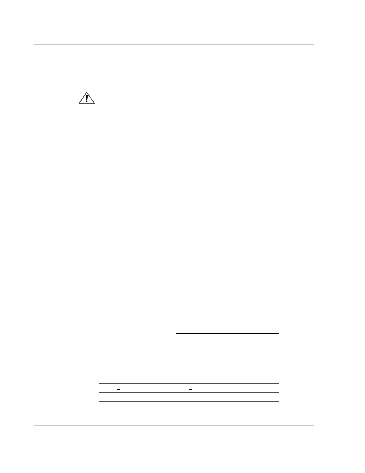
Table 1-1
Specification PV225S-480-P
Nom in al AC In pu t Voltage
(+10% to -12% acceptable range)
Maximum AC Output Current 271 A
Nom inal AC I n pu t Freq uency
(+0.5 to -0.7 Hz acceptable r ange )
Output Power 225 kW
Peak Power Tracking Window 300 to 600 Vdc
Maximum Open Circuit Voltage 600 Vdc
Maximum DC Input Current 781 amps
Electrical Specifications
Over Voltage, Under Voltage and Frequency Ranges
T able 1-2 provides the over voltag e, under voltage, over-frequency , and
under-frequency detection limits for the PV225S. These detection limits have
been factory tested and deemed to be in compli an ce with IEEE-292 and UL 1741
requirements for uti lity interaction.
Table 1-2
Vac Condition
(% of Nominal)
Vac < 50% Vac < 240 6 cycles
50% <
88% < Vac <
110% < Vac < 137% 528 < Vac < 657 2 seconds
137% <
f < rated -0.7 f < 59.3 6 cycles
f > rated +0.5 f > 60.5 6 cycles
Over/Under Voltage and Over/Under Frequency Ranges
Voltage Range Trip Time
Vac < 88% 240 < Vac < 422 2 seconds
110% 422 < Vac < 528 normal operation
Vac 657 < Vac 2 cycles
480 Vac
(422 to 528 Vac)
rms
60 Hz
(59.3 to 60.5 Hz)
PV225S-480-P
1–4 152606
Page 25

System Ground Requirements
This product is intended to be installed as part of a permanently grounded
electrical system pe r the National El ectric Code ANSI/NFPA 70. A copper gro und
rod must be installed within thr ee feet of the PV225S enclosures and connec ted to
the unit as described in “System Grounding” on page 3–12. The single-point
ground for the system is to be made at the AC ground bus bar (TB12) in the AC
Interface En clo sur e.
System Neutral Requirements
The PV225S is designed to be installed as a 4-wir e system. As required by the
UL 1741 listing, a neutral conductor from the util ity-interconnect must be
terminated at TB11 within the AC Interface Enclosure to ensure that the AC
voltage sensing circuit can per form an individual phase voltage (line-to-neutral)
measurement. The function of the neutral connection is to provide a point of
reference for measurement purposes that is essentiall y at ground potential. No
power will flow through the neutral conductor.
Utility Side Isolation Transformer Requirements
The PV225S is supplied with a high-efficiency custom Wye:Wye, isolation
transformer as part of the AC Interface/Transformer assembly. The utility side
windings of the isolation tr ansformer are configured Wye and must match the
voltage at the utilit y inter-tie. The PV225S is a balanced, three -phase,
current-sourcing inverter and only operates with the pres ence of a stable utility
voltage. The transformer is also supplied with a neutral connection on the utility
interconnect. Connection of this utility-side neutral does not affect the operation
of the inverter, however connection of the neutral on the inverter-side does affect
the operation and must be left floating or disconnected. Single-phase, grounded
loads which may be present between the transformer and utility, will maintain
their existing grou nd refer ence at the utility distribution transformer.
System Specifications
CAUTION: Equipment Damage
If the Isolation Transformer (T6-X0) neutral terminal is tied to ground, it will cause
irreparable damage to the PV225S. Check local regu lations for their requirements
regarding the connec tion of the neutral.
WARNING: Lethal Voltage
Grounding the neutra l of a W ye -wound transfor mer may create an “open delta ” condit ion ,
depending on the utility configuration. This condition may keep the PV225S from
detecting a loss of phase condition on the utility system, which may allow potentially
lethal volta ge to be present on the open-pha s e wiring.
152606 1–5
Page 26

Introduction
Environmental Specifications
The following environment al specifications are the same for both models of the
PV225S 225 kW Grid-Tied Phot ovoltaic Inverter.
Table 1-3
Specification Value
Dimensions
Weight
Allowab le A mb ien t Temperature
Relative Humidity To 95%, Non-condensing
Elevation Power Derated above 6600 ft
Clearan ce (ven t ila tion an d
serviceability)
Environmental Specifications
Inverter and DC Interface
Transformer and AC Interface
Overall System Footprint:
Layout Option A
Layout Option B
Inverter and DC Interface
Transformer and AC Interface
Overall Weight
Operating
Storage
88.5 in H x 80 in W x 32 in D
(225 cm H x 203 cm W x 81 cm)
49.5 in H x 61.5 in W x 35.5 in D
(126 cm H x 156 cm W x 90 cm D)
14 ft W x 5 ft L (approximate)
(4.3 m x 1.5 m)
10 ft W x 9 ft L (approximate)
(3 m W x 2.7 m L)
2300 lbs (approximate)
2350 lbs (approximate)
4650 lbs (approximate)
-20 °C to 50 °C Maximum
-40 °C to 50 °C Maximum
In front of access doors: 36 in (91 cm)
In front of access panels: 36 in (91 cm)
Sides: 12 in (30 cm)
Back: 6 in (15 cm)
Maximum Distance between Main
Inverter E ncl o sur e an d AC
Interface/Transformer Enclosure
1–6 152606
15 ft (4.5 m)
Page 27

Operator Interface Controls
Operator interface controls are located on the front door of the main inverter
enclosure. Thes e con tro l s includ e an O
keypad called the Universal F ron tpanel Control Unit (UFCU). Additionally there
is an AC and DC Disconnect on the AC Inter face Enclosure and the DC Inter fac e
Enclosure Doors.
Communication
Enclosure
Operator Interface Controls
N/OFF Switch, 4-line LCD display and
DC Disconnect
Switch (S2)
AC
Disconnect
Switch (S1)
Figure 1-2
AC Interface Enclosure
(AC Side View)
PV225S Operator Interface Components
LCD
Display
Universal
Frontpanel
Control
(UFCP)
ON/OFF
Switch
(S3)
Main Enclosure Door Interlock Switch
The front door of the P V225S main e nclosur e is equipped wit h a n interloc k s witch
to preclude operation while the front door is open. Opening the door of the main
inverter enclosu re will initiate an immediate controlled shutdown of the PV225S
and opens both the main AC and DC contac tors. The main AC and DC contactors
cannot be closed unless the door’s interlock is in the engaged position. The
PV225S is prevented from being resta rted until the door is again closed and the
switch is in the engaged position.
DC Interface
Enclosure
Main Inverter Enclosure
(Front View)
It is required tha t the PV225S main enclosure door must be locked during normal
operation. The door interlock switch does NOT remove all hazardous voltages
from inside the inverter. Before attempting to service the PV225S, follow the
de-energize Lockout and Tag procedure on page x.
152606 1–7
Page 28

Introduction
On/Off Switch
WARNING: Shock Hazard
Disengaging the main enclosure door interlock s witch does NOT remove all hazardous
voltages from inside the inverter. Before attempting to service the PV225S, follow the
de-energize Lockout and Tag procedure on page x.
The PV225S incorporates a maintained position ON/OFF switch (S3) located on
the front door of the main enclos ure. Under normal cond itio ns, the ON/OFF switch
is in the O
N position. Turning the switch to the OFF position will initiate an
immediate controlle d shutdown of the PV225S and opens both the main AC and
DC contactors within the unit . The main AC and DC contactors cannot be closed
unless the switch is in the
restarted until the O
ON position. The PV225S is prevented from being
N/OFF switch is turned back to the ON position.
WARNING: Shock Hazard
Turn ing the ON/OFF switc h to th e OFF position does NOT remove all hazardous voltages
from inside the in verter . Before attempting t o service the PV225S, follow the de-energize
Lockout and Tag procedure on page x.
Figure 1-3
ON/OFF Switch
(S3)
On/Off Switch (S3)
1–8 152606
Page 29

AC and DC Disconnect Switches
Both AC and DC In terface Enclos ures are eq uipp e d wi th loc k out ha s ps for
personnel safety. The enclosure doors should not be opened while the PV225S is
operating.
The switch handles and shafts pro vide a door interlock for both the AC and DC
Interface Enclos ures. The doors cannot be opened when the switch is in the
position.
The DC Disconnect Switch (S2) is equipped wit h an auxiliary contact block
which enables the switch to be used as a load break DC disconnect. In the event
the DC Disconnect Switch is opened while the PV225S is pr ocessing power from
the PV array, the early-break contact block will signal the CCU2 (Converter
Control Unit 2) to stop processing power prior to the opening DC Disconnect
Switch.
Additionally, opening the DC Disconnect Switch will cause the PV225S to
execute an immediate orderly shutdown, open both the main AC and DC
contactors, and report a PV disconnect fault on the LCD of the UFCU.
Communication Features
ON
DC Disconnect
Switch (S2)
AC Disconnect
Switch (S1)
AC Interface Enclosure
Figure 1-4
AC and DC Disconnect Switches (S1 and S2)
DC Interface Enclosure
Communication Features
The PV225S provides two types of information to the user:
• system status and/or fault information, and
• data logging informati on.
System status and fault info rmation can be accessed using the Universal Front
Panel Control Unit (UFCU) or a personal comput er using the Xantrex Solar
Graphic User Interface (GUI) software. Data logging requires the use of a PC
using the GUI software.
152606 1–9
Page 30

Introduction
System Status and Fault Reporting
Basic system status and all fault conditions rising from within the PV225S are
reported to the UFCU. The unit stores the time and det ails of all faults in
non-volatile memory. The 4-line LCD will display a hexadecimal value and a
brief text description of the fault.
This information can also be acce ssed using a personal computer using the GUI
software eit her directly or remote ly.
T ypes of status informatio n include:
• Current Oper at ing State o r Goa l State
• Fault Code (if applicable )
• Inverter St ate
• Line Voltage and Current
• Inverter Matrix Temperature
• Inverter Power
•PV State
• PV Voltage and Current
• PV Power
• Grid Frequency
• Peak Power Tracker Enabled
Data Logging
The inverter stores dat a values and software metrics for debugging. Thes e values
are stored within the CCU2 controller board in non-vola tile memory . Data logging
requires the use of a PC connection using the Xantrex Solar Graphic Use r
Interface (GU I) soft ware.
• The Data Logging features include :
• Operational Values
• Internal Metrics
• Data Log Acq ui s itio n
• Graphic Data Analysis
• Fault Log Acquisition
• Software Upgrade
• Accumulated Values
• Configurable Parameters
1–10 152606
Page 31

Communication Methods
The PV225S communicates system statu s information to the user using the
following methods.
• The Front Panel Control Unit (UFCU) Display
• PC Connection (Direct or Remote) - Xantr ex Solar Graphic User Interface
(GUI) Software required. Communication with a PC requires the selection of
one of the following options.
• Remote Connection -- This method has thre e options available. One of
these options will be field- installed prior to commission ing.
• POTS Connection
• Wireless Connection
• Ethernet LAN Connection
• Direct Connection -- This method is most commonly used by field
technicians for loca l connection and troubleshooting purposes.
Communication Methods
Important:
to support a PC connection. (i.e., makin g arra ngements for an analog phone line, wireless
service or local area network.)
The customer is responsible for providing the appropriate support service
Universal Front Panel Control Unit (UFCU)
The UFCU keypad is located on the front of the Main Inverter Enclosure to
manipulate and view system operation and status.
The keypad is comprised of 20 touch-sensitive keys that provide a means to
navigate through the menus and alter user-changeable settings.
Communications Enclosure
LCD
Display
Universal Front Panel
Control Unit (UFCU)
Figure 1-5
LCD Display and UFCU Location
See the PV225S 225 kW Grid-Tied Phot ovoltaic Inverter Operation and
Maintenance Manual for details.
152606 1–11
Page 32

Introduction
PC Connection Methods
Personal computers can be used to access the system status and programming
features of the PV225 S. A computer can be connected either dir e ctly or remotely.
1. Remote Connect - uses one of the three kits below.
• POTS Kit - uses a MultiTech® 56K Modem, RS232/Fiber Optic
• Wireless Kit - uses a GSM Wireless Modem.
• Ethernet LAN Kit - uses a da ta communication device to enable the unit
2. Direct Connect - This method is used for troubleshooting. It uses a
RS232/Fiber Optic Converter (configur ed for a PC), a DB25-to-DB25 gender
changer , and a DB25-to-DB9 Serial Cable.
Software is included to provide a graphic user interface that relates important
system information. This software is called Xantrex Solar Graphic Interface
(GUI). See "Computer Communications with the PV225S" in the PV225S 225
kW Grid-Tied Pho tovoltaic Inverter Operation and Maintenance Manual for
additional infor mation.
The GUI can dial up the inverter and receive fault report calls from it through a
standard Hayes-compatible, landline modem. When the GUI initiates a call
through the mode m at the GU I comp u ter, the inve rter’s modem answers the ca ll
and initiates a 9600 baud serial connection, effectively as if the GUI was
connected directly. Or, if the inverter experiences a fault, it will initiate a call to
the GUI and report the fault details.
Converter (configu red for ethernet) and SA2 Surge Arrest or.
to connect to a loca l area ne tw or k.
Communications
Enclosure
RS232/FO
Converter
MultiTech®
56K Modem
SA2 Surge
Arrestor
Figure 1-6
1–12 152606
PC Connections in the Communications Enclosure
POTS connection option shown.
Page 33

POTS Access
Communication Methods
Figure 1-7 illustra tes the PV225S connected remotely to a personal computer.
Figure 1-7
POTS Access
Wireless Access
Figure 1-8
Wireless Access
Figure 1-8 illustra tes the PV225S connected remotely to a personal computer
using a wireless network.
152606 1–13
Page 34

Introduction
Ethernet LAN Access
The PV225S can be remotely accessed throug h a local area network.
Figure 1-9
Ethernet LAN Access
Direct Access
Figure 1-10
Figure 1-10 illustra tes the PV225S connected directly to a personal computer.
Direct Access
1–14 152606
Page 35

2
Planning
Chapter 2, “Planning” provides informati on to help p la n the inst allat ion of
the PV225S 225 kW Grid-Tie d Photovoltaic Inverter.
Page 36

Planning
Overview of PV225S Installation
WARNING: Shock Hazard
Installations of this equipment should only be performed by qualified technicians.
Installers must meet all loc al and state code requirements for licensing and
training for the installation of Electrical Power Systems with AC and DC voltage
to 600 volts.
Planning Planning for a system requires complete understanding of all the components that
are involved to successfully install the PV225S to meet the required national,
state, and local codes.
Definition A power system (such a s the PV225S) is a collection of devices designed to
supply AC power to the utility grid from a solar energy (PV) source.
Components All types of gri d-tie d inve rter inst allations, re sident ial or industr ial, shar e common
components. This chapter describes each component and suggests the minimum
requirements for a safe installation.
Location The PV225S 225 kW Grid-Tied Photovolta ic Inverter is designed to be inst alled
in either an indoor or outdoor location. The PV225S must be anchored to a level,
concrete floor or pad.
Ideally the AC In terface Enclosur e/ Transf ormer Assembl y is placed on the lef t
side of the Main Inverter Enclosur e. The AC Interface Enclosure/Transformer
Assembly may be co-located adjacent to the left side of the Main Inverter
Enclosure up to, but not exceeding, 15 feet away.
Clearance Adequate ventilation and servic e access must be taken into consideration when
installing the PV225S. See “Ventilation and Serviceability Requirements” on
page 2–3 for specific clearance requirements and ambient temperature
requirements.
Conduits and
Conductors
Given the flexibility to co-locate the AC Interface Enclosure/Transformer
Assembly to fit a desired system layo ut, the conduits and conductors are to be
supplied by the installe r.
See “Conduit Penetration” on page 2–8 for recommendations on enclosure
penetration loca tions and conduit routing.
See “Conductor and Conduit Sizing” on page 2–11 for information on sizing the
conductors and conduits.
All interconnect wir ing and power conductors interfacing to the PV225S must be
in accordanc e with the Nati onal Electric Code ANSI/NFPA 70 and any applicable
local codes.
2–2 152606
Page 37

PV Planning
Large gauge wire must conform to the minimum bend radius specified in the
NEC, Article 373-6B, Ninth Edition.
T ake c are t o keep the wir e bund les away from a ny sharp e dges whi ch may da mage
wire insulation over time.
All conductors should be made of copper and rat ed for 90 °C (minimum).
If the installation of the PV225S is to be outdoors, all interconnect condui t and
fittings must be NEMA-4 rated as requir ed by the NEC.
PV Planning
To determine the number of photovoltaic panels that are required for the PV
power plant, please use the PV planning tool from the Xantrex website:
http://www.xantrex.com/support/pvsizing/disclaimer.asp
Ventilation and Serviceability Requirements
The following environment al conditions must be established and mainta ine d to
ensure the safe and efficient operation and servicing of the PV225S. Adequate
space must be provi ded aro und t he unit for v ent ilat io n and access during
servicing. If locating the unit indoors, ambient air temper ature cannot exceed the
maximum temperature for which the unit is rated.
Ventilation Maintain a minimum cleara nce of 12 inche s on both sides and 6 inches behind the
Main Inverter Enclosure and the AC Interface Enclosure for proper cooling fan
operation.
Maintenance and
Serviceability
Indoor Temperature
Control
152606 2–3
Maintain a minimum clearance of 36 inches in front of the Main Inverter access
door, the Transformer Enclosure access panel, and the AC Interface access door
for maintenance and serviceability.
See Figure 2-1 on page 2–6 and Figure 2-2 on page 2–7 for illustrations of these
clearance requirements.
If the PV225S is to be installed indo ors and external a ir is used for venti lation, the
required cubic feet per minute (CFM) rate must be no less than 1000 CFM. This
assumes the temperature inside the building is allowed to rise only 10 °C above
the outside temperatur e. There fore, the maximum allowable outside ambient
temperature is 50 °C (50 °C minus 10 °C equals 40 °C Maximum Ambient
Temperature).
If air conditioning is planned for an indoor installation, the heat load of the
PV225S is 42,000 BTU/Hour at full load.
Page 38

Planning
Ground Requirements
This product is intended to be installed as part of a permanently grounded
electrical syst em per National Electric Code ANSI/NFPA 70. A copper ground
rod must be insta lled within three f eet of the PV225S enclosur e. This is the single
point earth gr ound for the inverter s ystem. The single point ground for the system
is to be made at the AC ground bus bar (TB12) in the AC Interface Enclosure.
System Neutral Requirements
The PV225S is designed to be installed as a 4-wir e system. As required by the
UL 1741 listing, a neutral conductor from the util ity-interconnect must be
terminated at TB11 within the AC Interface Encl os u re to ens ure that the
AC voltage sensing circuit can perform an individual phase voltage (line-toneutral) measurement. The function of the neutr al connec tion is to provide a point
of reference for measurement purposes that is essentially at ground potential. No
power will flow through the neutral conductor.
Communication Requirements
The PV225S can accommodate any one of the following options f or PC
Communication:
• POTS Co nn ect Kit - uses a MultiTech
Converter (configu red for ethernet) and SA2 Surge Arrest or. A direct analog
phone line to the local phone service is requir ed to use this f eature . The phone
line used for PV225S communication cannot be routed through a Private
Branch Exchange (PBX) unless an analog PBX card is used.
• Wireless Connect - uses a GSM Wireless Modem.
• Ethernet LAN Connect - uses a data communication device to enable the
unit to connect to a local area networ k.
• Direct Connect Kit - uses a RS232/Fiber Optic Converter (configured for a
PC), a DB25-to-DB25 gender changer, and a DB25-to-DB9 Serial Cable.
Determine which communications options are required for the installa tion and
procure the a ppropria te ser vice or phone a ccess. The per sonal computer to be used
with this unit must have the appropriate hardware as well, such as a 56K modem
for dial up connection or a Network Interface Card (NIC) for a LAN connection.
®
56K Modem, RS232/Fiber Optic
2–4 152606
Page 39

Utility Side Isolation Transformer Requirements
Utility Side Isolation Transformer Requirements
The PV225S is supplied with a a high-eff iciency custom W ye:W ye isolation
transformer as part of the AC Interface/Transformer assembly. The utility side
windings of the isolation tr ansformer are configured Wye and must match the
voltage at the utilit y inter-tie. The PV225S is a balanced, three -phase, currentsourcing inverter and only operates with the presence of a stable utility voltage.
The transformer is also supplie d with a neutral connection on the utility
interconnect. Connection of this utility-side neutral does not affect the operation
of the inverter, however connection of the neutral on the inverter-side does affect
the operation and must be left floating or disconnected. Single-phase, grounded
loads which may be present between the transformer and utility, will maintain
their existing grou nd refer ence at the utility distribution transformer.
CAUTION: Equipment Damage
If the Isolation Transformer (T6-X0) neutral terminal is tied to ground, it will cause
irreparable damage to the PV225S. Check local regu lations for their requirements
regarding the connec tion of these neutrals.
WARNING: Lethal Voltage
Grounding the neutra l of a W ye -wound transfor mer may create an “open delta ” condit ion ,
depending on the utility configuration. This condition may keep the PV225S from
detecting a loss of phase condition on the utility system, which may allow potentially
lethal volta ge to be present on the open-pha s e wiring.
Electrical Diagrams and Schematics
Since installations vary widely, a sample electrical diagram of the PV225S is
provided in Figure A-1 on page A–3. This diagram is to be used for system
planning purposes only.
For mo re de tailed infor m atio n , r e fer to the schema t i c il lustr ations.
• Figure A-2, “PV225S Schematic for Main Power Distribution (152812 A1)”
on page A–4
• Figure A-3, “PV225S Schematic for Control Power Distribution
(152812 A2)” on page A–5
• Figure A-4, “PV225S Schematic for Conv erter Control Unit (152812 A3)” on
page A–6
152606 2–5
Page 40

Planning
Layout Options
The PV225S is shipped as two separ ate assemblies and can be arranged as shown
in Figure 2-1 or Figure 2-2.
The PV225S can be arrang ed in a number of different system layout options to fit
specific site requir ements. The AC Interface/T ransformer assembly may be colocated adjacent to the left side of (or behind) the Main Inverter Enclosure up to,
and not exceeding, 15 feet away.
Given the flexibili ty to co-locate the AC Interface/Transformer assembly to fit a
desired system layout , the interconnect AC power conductors and conduit
between the Main Inverter Encl osure and the AC interface/transformer assembly
are to be supplied by the installe r. See Figure 2-1 and Figure 2-2, depicting two
options for locatin g the AC interface/transformer assembly adjacent to the main
inverter.
Minimum Dimension of Base:
Approximately 14 ft. by 5 ft. (4.3 m x 1.5 m)
Figure 2-1
2–6 152606
PV225S Layout Option A
Page 41

Minimum Dimension of Base:
Approximately 10 ft by 9 ft (3 m x 2.7 m)
Layout Options
Figure 2-2
152606 2–7
PV225S Layout Option B
Page 42

Planning
Conduit Penetration
The following il lustrati ons sho w the r ecommended loc ations f or ele ctri cal condu it
entry into the PV225S enclosures. These drawings are to be used for system
planning purposes, such that the shaded areas are representative of the maximum
allowable area and locat ion in which electrical conduit may penetrate the
enclosures of the PV225S, see Figure 2-3 through Figure 2-8. Xantrex
recommends a standard trade-size conduit knock-out set for cutting/punching the
PV225S enclosures and panels for conduit entry.
AC Interface
Enclosure
AC side view
of PV225S
E
Transformer
Enclosure
B
A
AC Interface
Enclosure
C
Main Inverter
Enclosure
Inductor
Enclosure
Front view of PV225S
Figure 2-4 on page 2–9
A
B
Figure 2-5 on page 2–9
C
Figure 2-6 on page 2–10
Figure 2-7 on page 2–10
D
E
Figure 2-8 on page 2–10
DC Interface
Enclosure
D
Figure 2-3
Conduit Entry Figure Reference
2–8 152606
Page 43

Conduit Penetration
5 ½" (15 cm)
1 ½" (4 cm)
18" (46 cm)
6" (15 cm)
Figure 2-4
Inductor Enclosure Conduit Entry, Left Side
1 ½" (4 cm)
5 ½" (15 cm)
18" (46 cm)
6" (15 cm)
Figure 2-5
152606 2–9
Transformer Enclosure Conduit Entry, Right Side
Page 44

Planning
Backside of
Transformer
Enclosure
(partial view)
8"
(20 cm)
AC Disconnect Switch (S1)
10" (25 cm)
1" (2.5 cm)
12" (30 cm)
5" (13 cm)
Figure 2-6
Figure 2-7
AC Interface Enclosure Conduit Entry, Left Side
DC Interface Enclosure, Bottom Side
3" (8 cm)
1" (2.5 cm)
18"
(45 cm)
2" (5 cm)
10" (25 cm)
4" (10 cm)
10.5" (27 cm)
1" (2.5 cm)
Figure 2-8
2–10 152606
Communications Enclosure Conduit Entry, Bottom Side
Page 45

Conductor and Conduit Sizing
All wiring methods and materials shall be in accordance with the National
Electrical Cod e ANSI/NFPA 70. When sizing conducto rs and condu its i nterfa cing
to the PV225S, both shall be in accordance with the National Electric Code ANSI/
NFPA 70, as well as all state and local code requirements.
Large gauge wire must confo rm to the minimum bend radius dependent upon the
wire gauge (refer to the National Electric Code, Article 373-6B (Ninth Edition).
CAUTION: Equipment Damage
Be careful to keep the wire bundles away from any sharp edges which may damage wire
insulation over time.
The following provide s information on sizing the con ductors and conduits for the
system.
To calc ul ate the proper condui t size :
1. Determ in e the req ui red cab l e am p acit y.
2. Determine the conduit length be tween the inverter and the transformer.
Conductor and Conduit Sizing
3. Determine the prope r size for the cable according to the allowable ampacitie s
indicated by NEC Table 310.16 (Ninth Edition).
4. Determine the proper size for the conduit.
The following is an example of the steps outlined above. Assumptions were made
in this example which may not match your application, and the resulting design
may not comply with all code requirements. Consult a licensed electrician on
recommendations for specific installations.
Step 1. Determine the required cable ampacity.
AC Phase Cab les from Inv erter t o Transfo rm er:
225 kW / 208 Vac / 1.732 = 624.5 A
624.5 x 125% = 780.69 A (required ampacity)
Step 2. Determine the conduit length between inverter and transformer.
• If the conduit length between the inverter and the transformer is less than
24 inches, then the cable can be sized using the NEC Table 310.16
(in raceway) (Ninth Edition).
• If the conduit length is greater than 24 inches, then the cable m ust be sized
using NEC Table 310.16 (in Raceway) (Ninth Edit ion) and by using the
adjustment factors in NEC Table 310-15(b)(2)(a).
(full load current)
rms
152606 2–11
Page 46

Planning
Step 3. Size the cable.
This example assumes that the condui t length is less than 24 inches. NEC
Table 310.16 (Ninth Edition) indicates the Temperature Correction Factor for
90 °C THHN cable in a 50 °C ambient is 0.82. With a required ampacity from
Step 1 above of 780.6 amps, it can be calcul ated that the required cable ampacity
at 50 °C in this application is 952 amps. (780.6 divided by 0.82)
In this example, four cables per phase termination are used, so from NEC Table
310.17 (Ninth Edition) it is apparent that the 90 °C THHN cable must be
262 kcmil or larger. Four each 262 kcmil conductors at 50°C have an allowable
ampacity of 984 amps (246 multiplied by 4).
Step 4. Size the conduit.
In this step, the cross sectional area of all the individual cables is first calculated.
Once calculated, the total cross sectional area of the cables is determined by
summing their values. In this example, 262 kcmil DLO, 2000 V cable is selected
for the AC Phase connections:
DLO 262 Phase Cable:
262 MCM DLO, 2000V, 90 °C per Phase
262 MCM has an O.D. of 0.973
0.973 x 0.973 x 12 x 0.7854 = 8.923 in²
Ground Cable:
1 Each #2 A WG (per NEC Tabl e 250. 122 (Ninth Edition),
using 400 A Breaker)
#2 AWG has an O.D. of 0.384 for THHN and 0.565 for DLO
0.565 x 0.565 x 0.7854 = 0.250 in²
Sense/Control Wires:
8 Each #16 A WG, UL1015, THHN, Hook-up Wire
#16 AWG has an O.D. of 0.096
0.096 x 0.096 x 8 x 0.7854 = 0.058 in²
Total:
DLO 262 Phase Cable = 8.923 in² (8.923 divided by 2 = 4.46)
Ground Cable = 0.250 in²
Sense/Control Wires = 0.058 in²
2 runs of conduit between the Isolation Transformer (T6-X1, T6-X2, and T6-
X3) and the Main Inverter Enclosure (T B5, TB6, and TB7)
1st conduit run; 4.46 + 0.25 = 4.71 in²
2nd conduit run; 4.46 + 0.058 = 4.52 in²
2–12 152606
Page 47

Using the "Over 2 Wires" column per NEC Chapter 9, Table 4, (Ninth Edition)
indicates that the fol lowing minimum permitted conduit trade size is acceptable
for the 21 w i re s in this ex erc ise:
EMT = 3 ½" Trade size
IMC = 4" Trade size
RMC = 4" Trade size
Anchoring the PV225S
The PV225S is designed to be installed in eithe r an indoor or outdoor location. It
must be placed on and anchored to a level concrete floor or pad. The concrete
floor or pad, upon which the PV225S is anchored, must be structurally de signed to
meet any local, stat e, or nati onal requi rement s for weight, seismic, and wind shee r
if applicable.
Four 5/8" holes are provid ed in the feet of the main inve rter, and six 5/8" holes are
provided in the feet of the AC interfa ce/t ransformer assembly for ancho ring to the
floor or pad.
Figure 2-9 and Figure 2-10 depict the layout patterns of the anchoring holes for
both the PV225S main inverter and the AC interface/transformer assembly.
Anchoring the PV225S
23 ¼"
(59 cm)
Figure 2-9
(43 1/8”)
(110 cm)
Main Inverter Anchor Bolt Pattern (Not to scale)
5/8"
(1.5 cm)
(x4)
152606 2–13
Page 48

Planning
(30”)
(76 cm)
17 ¼"
(43 cm)
(38”)
(97 cm)
¾" (1.9 cm)
(x6)
Figure 2-10
AC Interface/Transformer Anchor Bolt Pattern (Not to Scale)
The floor or pad should either be pre-drilled to accept masonry anchors or have
pre-install ed anchoring bolts.
2–14 152606
Page 49

3
Installation
Chapter 3, “Installation” describes the procedures needed to install
the PV225S 225 kW Grid-Ti ed Photovoltaic Inverter. This section
includes unpacking and moving instructions, mounting instructions,
and cabling instructions.
Page 50

Installation
Equipment Required
The following is a list of required tools and equipment to ai d in the installation of
the PV225S. This list is not a comprehensive list, but is intended to help identify
the minimum recommended tools and equipment used during the installation.
• Forklift (26" minimum fork span) and/or pallet jack
• Claw hammer or pry bar
• Standard and metri c socket set
• Standard and metri c wrench set
• Standard Allen
• Large slip-j oint pliers
• Standard and Phil lips screwdrivers
• T orque wrench with 0 - 600 in-lbs minimum range
• Appropriate voltage meter (6 00 Vac and DC rated, minimum)
• Phase rotation meter (600 Vac rated, minimum)
• Hammer drill and masonry bits
• Trade-size conduit knock-out set
®
Hex wrenches (5/16, 3/8, and 1/2)
Unloading
The PV225S is shipped partially as sembled in two separate shipping crates and
one cardboard box.
❐ One crate is the main inverter and is marked "1-152287-01".
❐ The other crate is the AC Interface Enclosure and transformer assembly and is
marked "1-152448-01".
❐ The cardboard box contains one of the three remote connection kits:
• POTS Connection 1-152674-01,
• Wire less Connection 1-152659-01, or
• Ethernet Connection 1-152658-01.
WARNING: Heavy Equipment
The main inverter weighs approximately 230 0 lbs. The AC Interface Enclosure and
transformer as sembly weigh approximately 2350 lbs. Attempting to lift the equipment by
other than the recommended lifting points may damage the equipment or present a
personnel safety hazard and void the warranty. Keep all t he doors closed and lat che d when
moving the enclos ures. Leaving the door latches unsecured may result in damage to the
unit and void the warranty.
3–2 152606
Page 51

Moving the PV225S
CAUTION: Equipment Damage
c
To move the PV225S, use a forklift that has a sufficient lift capacity and has a 26" fork
span.
To move the PV225S while it is still inside the shipping crates:
1. Place the forks of the forklift below the shipping crate at the points specified
2. Lift the main inverter and the AC Inter face Enclosure and Transformer
Unloading
on the shipping crate.
Enclosure from beneath their shipping crates.
Figure 3-1
Moving the crated PV225S
Unpacking the PV225S
To unpack the main inverter and the AC Interface Enclosure and
transformer assembly from their shipping crates:
1. Using a claw ha mmer or pry bar, remove the c rate’s wood top and si de panels.
2. Remove the main inverter’ s an chor hardware that attaches it to the shippi ng
pallet.
3. Remove the AC Interface Enclosure and trans former assembly anchor
hard w are th a t a t taches them to their sh ippin g pall e t .
152606 3–3
Page 52

Installation
Removing the Pallet and Moving the PV225S
CAUTION: Equipment Damage
c
To move the PV225S, use a forklift that has a sufficient lift capacity and a 26" fork span.
To move the PV225S using a forklift:
1. Place the forks of the forklift below the unit at the points specified in
Figure 3-2.
2. Lift the PV225S from beneath the respective enclosures.
Be sure to use a forklift with a 26" fork span.
3. Remove the pallet from beneath the unit.
4. Once the pallets are removed from the units, use the same lifting locations to
lift the units into the place where they are to be per ma n ently loca t ed.
Lift Here
26" (66 cm)
fork span
Figure 3-2
3–4 152606
Forklift Lifting Locations - Underneath Unit
Lift Here
26" (66 cm)
fork span
Page 53

Mounting and Anchoring the Units
Important:
of the components , conduit penetrati on locations, conductor and conduit sizing, and
method for anchoring the unit. Ensure adequate space is provided for clearance for
ventilation and serviceabilit y. Review Chapter 2, “Planning” if necessary before
proceeding.
Before proceeding with the installa tion, determine th e loc ation and layout
Mounting and Anchoring the Units
To mount and anchor the PV225S:
1. Predrill the floor or pad to accept 1/2" diameter masonry anchors or ensure it
has pre-installe d anchoring bolts that will fit the 5/8" mount ing holes.
2. Lift the main inverter from beneath the lower enclosure with a forklift or
pallet jack as shown in Figure 3-2 on page 3–4. Move the Main Inverter
Enclosure into place.
3. Lift the AC Interface/Transformer assembly from beneath the enclosure with
a forklift or pallet ja ck as shown in Figure 3-2 on page 3–4. Move the AC
interface/t ransformer assembly into place.
4. Secure the Main Inverter Enclosure feet to the floor with a 1/2" diameter
anchor bolts.
5. Secure the AC Interface/Transformer assembly enclosure feet to the floor
with 1/2" diameter anchor bolts.
Mounting Holes for
securing and anchoring
the units.
Figure 3-3
152606 3–5
Mounting Hole Locations
Page 54

Installation
Opening or Closing Access Doors
To lock or unlock the front door on the main inverter:
1. Use the 7 mm triangle key provided with the unit.
a) Insert the key in each lock and turn counterclockwise to open;
clockwise to lock.
b) Pull front door open from the right sid e.
Main Inverter Front Door Locks
Main Inverter Front Door Lock
Figure 3-4
3–6 152606
Inverter Enclosure Access Doors
Page 55

Door Latches
h
Opening or Closing Access Doors
To Op en A cce s s Doo r:
1. Confirm that th e AC Di sconne ct Switc h
handle is placed in the OFF (Open)
position prior to opening the door.
2. Loosen the bolts on door latches and
slide away from the d oor.
3. Pull open from right side.
To Close Access Door:
1. Confirm that the AC Disconnect Switch
handle is pl aced i n the OFF (O p en)
position prior to closing the door.
2. Close the door and slide the latches
back over the edge of the door .
3. Tighten the bolts on door latches.
Figure 3-5
AC Interface Access Door
T o Open Access Door:
1. Confirm that the DC Dis connect Switch
handle is placed in the OFF (Open)
position prior to opening the door.
2. Loosen the bolts on door latches and
slide away from the door.
3. Pull open from the left side.
To Clos e A cce ss Do o r:
1. Confirm that t he DC Disconne ct Switc
handle is placed in the OFF (Open)
position prior to closing the door.
2. Close the door and slide the latches
back over the edge of the door.
3. Tight en the bolts on door latches.
Door Latches
Figure 3-6
152606 3–7
DC Interface Access Door
Page 56

Installation
Transformer Access Panel
Figure 3-7
Transformer Access Panels
To Remove the Access Panel
Loosen and remove the 1/4"
self-tapping sheet metal screws
(x9).
To Replace the Access Panel
Replace and tighten the 1/4"
self-tapping sheet metal screws.
Main Inverter Front Door
Inductor Access Panel
:
:
Figure 3-8
To Remove the Access Panel
Use a Phillips screwdriver to loosen
and remove the 1/4-20 Phillips
round-head bolts (x12).
To Replace the Access Panel
Replace and tighten the 1/4-20
Phillips round-head bolts to 78 in-lb
(8.6 nm).
Inductor Access Panels
:
:
3–8 152606
Page 57

Conduit Installation
Given the flexible nature of the syste m, conduit installation will be depende nt
upon the final configuration of the system. Procurement and installation of the
conduit, therefore, is the responsibility of the installer. Since the layout will be
dependent upon the locati on availa ble for the installation and the siz e of the
conductors used, specific conduit size and type must be pre-determined by the
installer befor e the actua l installation. See “Conductor and Conduit Sizing” on
page 2–11 for instructions on how to determine the size of the conductors and
conduits to be used. Once the size of the conductors and conduits has been
determined, follow the instructions below for instal ling the conduits. Be sure to
consult the NEC Handbook and any local codes to ensur e code compli ance.
Conduit Installation
Important:
PV225S be NEMA-4 rated.
To install the conduits:
1. Determine the conduit penetration locations in the Main Inverter Enclosure
and the AC interface/transformer assembly. See Figure 2-3 on page 2–8
through Figure 2-5 on page 2–9.
2. Install appropriately sized conduit based upon system layout and required
codes between the main inverter and the AC interface/transformer assembly.
For ease of conduit install ation, the access panels on both the main inverter
and the AC interface/transf ormer assembly can be removed.
3. Determine all remaining conduit penetration locations in the AC Interface
enclosure, DC Interface Enclosure, and Communication Enclosure. See
Figure 2-3 on page 2–8 through Figure 2-8 on page 2–10.
4. Install all remaining appropriately sized conduit interfacing for the AC
Interface En clo sur e, D C Int erf ace Encl o sur e, and Communicati on Encl os ure
based upon system layout and require d codes.
Outdoor install ations require that al l conduit fittings interfacing with the
Conduit
Figure 3-9
152606 3–9
Conduit Installation
Page 58

Installation
Wiring - General
All wiring methods and materials shall be in accordance with the National
Electrical Cod e ANSI/NFPA 70. When sizing conducto rs and condu its i nterfa cing
to the PV225S, both shall be in accordance with the National Electric Code
ANSI/NFPA 70, as well as all state and local code requirements.
WARNING: Shock Hazard
The PV225S enclosures contain exposed high-voltage conductors. The enclosure doors
should remain cl osed with the latches tightened, except during installation, maintenance
or testing. These servicing instructions are for use by qualified personnel who meet all
local and state code requirements for li ce nsing and training for the installation of
Electrical Power Systems with AC and DC voltage to 600 vol ts. To reduce the risk of
electric shock, do not perform any servicing other than that specified in the installation
instructi ons unless you are qualified to do so. Do not open the cabinet doors if extreme
moisture is present (rain or heavy dew).
WARNING: Lethal Voltage
In order to remove all sources of voltage from the PV225S, the incoming power must be
de-energized at the source. This may be done at the main utility circ uit breaker and by
opening the AC Disconnect and the DC Disconnect Swi tches on the PV225S. Review th e
system configura tion to determine all of the possible sources of energy. In addition, allow
5 minutes for the DC bus capacitors, located on the cei ling of the cabinet, to dis charge
after removing power.
CAUTION: Equipment Damage
When connecting external AC wires to the PV225S, positive phasing sequence must be
maintained throughout the installation proces s. Refer to the system sche ma tics in
Appendix A of this manual for proper phasing convention.
Important:
damage wire insulation over time. Consult the NEC ANS I/NFPA 70 Code Book to ensure
code compliance.
The model PV225S has a three-phase output. It is marked with this symbol:
Conductor size should have been pre- determined when the conduit was installed.
Prepare the appropriate length conductors for each connection.
3–10 152606
Take care to keep the wire bundle s away from any s harp edges which may
Page 59

Overcurrent Protection
AC overcurrent prot ection for the Utility I nter connect (Gr id-tie) must be provid ed
by the installer as part of the PV225S installation.
CAUTION: Equipment Damage
In accordance with th e NEC, ANSI/ N F PA 70 (Ninth Edition) a 400 A maximum
branch-circuit overcurrent protection must be provided.
Conductor Termination
The PV225S has terminals and bus bars for making all wiring connections
required for the insta llation. All terminals used for making AC and DC
connections requir e the use of copper conductors with an insulation rating of
90 °C (or higher). For wire gauge, bolt size, and torque value s for the AC
terminals, see Table 3-1. For wire gauge, bolt size, and torque values for the
DC terminals, see Table 3-2.
Wiring - General
Transformer
Enclosure
Main Inverter
Enclosure
AC Interface
Enclosure
DC Interface
Enclosure
The AC terminals in the Tr ansformer Enclosure (T6-X1, T6-X2, and T6 -X3 )
require the use of crimp-on type ring terminals or compression-type lugs. The
terminals can accommodate up to two conductors per phase.
See Figur e 3-14 on page 3–15 for the location of these terminals.
The AC terminals in the Main Inverter Enclosure (TB5 , TB 6, and TB7) have six
openings per phase. These terminals do not require the use of ring terminals or
compression lugs.
See Figure 3-15 on page 3–16 for the location of these terminals.
The AC line terminals in the AC Interface Enclosure (S1-2T1, S1-4 T 2, and
S1-6T3) are one bolt per phase. These terminals require the use of crimp-on type
ring-terminal s or compression-type lugs.
See Figur e 3-16 on page 3–16 for the location of these terminals.
The AC neutral terminal in the AC Interface Enclosure (TB11) has one bolt per
pole and requires the use of crimp-on type ring terminals or compression-t ype
lugs.
See Figur e 3-18 on page 3–18 for the location of this terminal.
The DC terminals in the DC Interface Enclosure (S2-6, K2-6T3, and TB4) can
accommodate up to four conductors per pole at S2-6 and K2-6T3, and up to two
conductors at TB4. These terminals do not require the use of ring-terminals or
compression lugs.
See Figur e 3-19 on page 3–19 for the location of these terminals.
Important:
pass through the same knockout and conduit fittings, thus allowi ng any inductive currents
to cancel.
152606 3–11
Keep these cables together as much as possible, and ensure that all cables
Page 60

Installation
Wire Gauge and Torque Requirements
T able 3-1 provides acceptable wire gauges, bolt sizes, and torque values f or AC
terminal connections.
Table 3-1
AC Terminal
Connections
TB1
(Chassis Ground)
TB12
(System Ground)
TB11 (Neutral) 500MCM to #4 AWG (1 stud per pole) 3/8-16 228 in-lb (25.7 Nm)
S1-2T1, S1-4T2,
S1-6T3
T6-X1, T6-X2,
T6-X3
TB5, TB6, TB7 350MCM to #4 AWG (6 openings per phase) 3/8 Hex 375 in-lb (42.4 Nm)
AC Terminal Wire Gauge, Bolt Size, and Torque Values
Acceptable Wire Size Range
(both models)
500MCM to #4 AWG (1 stud per pole) 3/8-16 420 in-lb (47.5 Nm)
500MCM to #4 AWG (1 stud per pole) 3/8-16 420 in-lb (47.5 Nm)
350MCM to #6 AWG (1 stud per phase) M10 (See Caution
350MCM to #6 AWG (2 studs per phase) 3/8-16 420 in-lb (47.5 Nm)
Bolt (Hardware)
Size
on page 3–18)
Tor qu e
Requirements
310 in-lb (35.0 Nm)
T able 3-2 provides acceptable wire gauges, bolt sizes, and torque values f or DC
terminal connections.
Table 3-2
DC Terminal
Connections
S2-6, K2-6T3, TB4 600MCM to #4 AW G (2 openings per pole) 1/2 Hex 600 in-lb (67.8 Nm)
DC Terminal Wire Gauge, Bolt Size, and Torque Values
Acceptable Wire Size Range
(both models)
Bolt (H ardw are)
Size
Tor qu e
Requirements
Grounding
System Grounding Install a copper ground rod with in three feet of the PV225S enclosures per the
National Elec tric Code ANSI/NFPA 70. The single -point ground for the system is
to be made at the AC ground bar (TB12) in the AC Interface Enclosure.
AC Ground Bar
(TB12) to be used
for the Single Point
Ground
AC Interface Enclosure
Figure 3-10
3–12 152606
Single-point Ground (TB12) Ground Bar
Page 61

Wiring - General
Chassis Ground The chassis ground is a copper bus bar in the Main Inverter Enclosure and has
3/8-16" bolts for terminating the AC ground. The ground conductor size depends
on the size of the main circuit breaker.
NEC Table 250.122 (Ninth Edition) requires t hat the ground conductor be at le ast
#3 AWG for a 400 A circuit breaker .
T orque connections to ground bar in the Main Invert er Enclosure to
420 in-lb (47.5 Nm).
The equipment ground on the PV225S is marked with this symbol:
Main Inverter Enclosure
Figure 3-11
Chassis Ground Bar (TB1)
DC Interface Enclosure
AC Ground Bar (TB1)
to be used for the
Chassis Ground
Array Grounding NEC Article 690-41/42 (Ninth Edit ion) requires the PV array to be earth
grounded. The PV225S chassis is al so bonded to the PV safety ground terminal
block.
System Neutral Requirements
The PV225S is designed to be installed as a 4-wir e system. As required by the
UL 1741 listing, a neutral conductor from the util ity-interconnect must be
terminated at TB11 within the AC Interface Enclosure to ensure that the
AC voltage sensing circuit can perform an individual phase voltage
(line-to-neutr al) measurement. The function of the neutr al connection is to
provide a point of reference for measurement purposes that is essentia lly a t
ground potential. No power will flow through the neutral conductor.
Utility Side Isolation Transformer Requirements
The PV225S is supplied with a a high effic iency custom Wye :Wye isolation
transformer as part of the AC interface/transformer assembl y. The utility side
windings of the isolation tr ansformer are configured Wye and must match the
voltage at the utilit y inter-tie. The PV225S is a balanced, three -phase,
152606 3–13
Page 62

Installation
current-sour cing inverter and only operates with the presence of a stable utility
voltage. The transformer is also supplied with a neutral connection on the utility
interconnect. Connection of this utility-side neutral does not affect the operation
of the inverter, however connection of the neutral on the inverter-side does affect
the operation and must be left floating or disconnected. Single-phase, grounded
loads, which may be present between the transf ormer and utility, will maintai n
their existing grou nd refer ence at the utility distribution transformer.
CAUTION: Equipment Damage
If the Isolation Transformer (T6-X0) neutral terminal is tied to ground, it will cause
irreparable damage to the PV225S. Check local regu lations for their requirements
regarding the connec tion of these neutrals.
WARNING: Lethal Voltage
Grounding the neutra l of a W ye -wound transfor mer may create an “open delta ” condit ion ,
depending on the utility configuration. This condition may keep the PV225S from
detecting a loss of phase condition on the utility system, which may allow potentially
lethal volta ge to be present on the open phase wiring.
Wiring - Specific
This section provides information for connecting the AC and DC conductors,
ground conductors, and AC Sense Harness.
AC Connections
To connect the main inverter to AC interface/transformer assembly:
1. Remove the access panels from the front of both the Main Inverter Enclosure
and the Tra nsformer Enclosure. Additionally, open the front door to the Main
Inverter Enclosure .
2. Route the AC power conductors A, B, C phase cables and ground conductor
through the conduit between the m ain inver ter to the AC in terfa ce/t ransformer
assembly (T6).
Route the AC cables from the Inverter
Enclosure through the conduits to the
Transformer Enclosure.
AC Sense Harness (partially
hidden below AC Cables)
Inductor Enclosure
Transformer Enclosure
Figure 3-12
3–14 152606
Route AC Cables through the Conduit
Page 63

Wiring - Specific
3. In addition to the power conductor s, route the AC Sense Harness assembly
(Xantrex P/N 1-152403-01) between the main inverter to the AC
interface/t ransformer assembly. Prior to completing the ins tallation of the AC
Sense Harness, secure the harness to the AC power conductors with nylon
tie-wraps so it does not touch the surfaces of either the L3 or L4 inductor.
Failure to secur e the A C Se nse Harness awa y from these s u rfac es may cau s e
deformation of the harnes s insula tion and possibly damage due to the
excessive heat genera ted by the L3 or L4 inductor.
Prior to completing the installation
of the AC Sense Harness, secure
the harness to the AC power
conductors with nylon tie-wraps.
Figure 3-13
4. Connect the AC power conductors in the T ra nsforme r Enclosure at the T6-X1
AC Interface Enclosure
Tie-wraps on the AC Sense Harness
(A phase), T6-X2 (B phase), and T6-X3 (C phase) bus bars using
3/8-16" hardware. Connect the ground conductor in the AC
Interface/Transformer Enclosure at TB12. Cables to these terminals must use
a crimp-on type ring terminal or compression-type lug. Tighten th ese
connections to a torque value of 420 in-lb (47.5 Nm).
TB12 Ground Bar
Ground Cable
from Main
Inverter
Enclosure
T6-X3
T6-X2
T6-X1
Transformer Enclosure
Figure 3-14
152606 3–15
AC Terminal Connections in the AC Interface/Transformer Enclosure
Page 64

Installation
5. Connect the AC power conductors in the Main Invert er Enc losure at TB5
(A phase), TB6 (B phase), and TB7 (C phase) with a box connector using a
3/8" Hex screw. This hardware should be tightened to a torque value of
375 in-lb (42.4 Nm). Connect the ground conductor to the TB1 terminal on
the ground bar on the right side of the enclosure. Torque this connection to
420 in-lb (47.5 Nm).
TB7
TB6
TB5
TB1
Figure 3-15
AC Interface Enclosure
AC Terminal Connections in the Main Inverter Enclosure
S1-2T1
(A phase)
S1-4T2
(B phase)
Enlargement of
Terminal Connectors
in the AC Interface
Enclosure
S1-6T3
(C phase)
Figure 3-16
AC Terminal Connections in the AC Interface Enclosure
3–16 152606
Page 65

Wiring - Specific
6. The AC Sense Harness is pre-terminated within the AC interface/transformer
assembly and the opposite end is mated with its 9-pin plug to the
corresponding 9-pin ja ck within the Main Inverter Enclosure.
See Figure 3-17.
Figure 3-17
Connecting the AC Sense Harness
7. Replace the access panels on the front of both the main inverter Inductor
Enclosure and the Transformer Enclosure. Additionally, close the front door
to the Main Inverter Enclosur e.
To connect the utility service to AC Interface Enclosure:
1. Remove the door clamps and open the door to the AC Interface Enclosure.
2. Route the AC power conductors A, B, C phase, neutral, and a neutral gr ound
cable through the conduit from the utility service to the AC Interface
Enclosure. See Figure 3-18 for the location of these terminals.
3. Connect the AC power conductors at the S1-2T1 (A phase), S1-4T2
(B phase), and S1-6T3 (C phase) terminals using the M10 hardware. Cables to
these terminals must use a crimp-on type ring terminal or compression-ty pe
lug. Torque these connections to 310 in-lb (35.0 Nm). See Figure 3- 18 for the
location of these termin als.
4. Connect the neutral conductor a t TB11. Connect the ground conductor at
TB12. Terminations for the neut ral and ground conductors within the AC
Interface Enclos ure at the TB11 and TB12 locations are made with 3/8-16"
hardware. Cables to these te rminals must use a crimp-on type r ing terminal or
compression-type lug. The terminal at TB11 should be tight ened to a torque
value of 228 in-lb (25.7 Nm). The terminal TB12 shou ld be tightened to a
torque value of 420 in-lb (47.5 Nm). See Figure 3-18 for the location of these
terminals.
5. Close the door to the AC Interface Enclosure and replace the door clamps.
152606 3–17
Page 66

Installation
CAUTION: Equipment Damage
The terminati on points of the AC power conductors at S1 inclu de a captive nut and plas tic
insulator between the terminals and the panel. Ensure the length of the connection
hardware used to attach the AC power conductors at S1-2T1-, S1-4T2, and S1-6T3, does
not "bottom-out" to the plastic insulator . The depth of the hole at terminals of S1 is ½"
from the top of t he tab. Failure to observe this m ay result in failure of the plastic insulato r
and may cause a direct sho rt to ground.
Figure 3-18
TB11
Neutral
S1-6T3
S1-2T1
(A Phase
terminal)
(B Phase terminal)
(C Phase
terminal)
S1-4T2
Ground TB12
AC Terminal Connections from the Utility
3–18 152606
Page 67

PV Array Connections
To make the connections from the PV Array/combiner to DC Interface
enclosure:
1. Remove the door clamps and open the door to the DC Interface Enclosure.
2. Route the PV Array cables conductors POSitive (PV+), NEGative (PV-), and
3. The DC power conductor terminations a re made at the S2-6 (POS/DC+), and
4. Terminations for the S2-6, K2-6T3, and TB4 terminals are made with box
5. Close the door to the DC Interface Enclosure and replace the door clamps.
Wiring - Specific
PV GND through the conduit to the DC Interface Enclosure, enteri n g on the
underside.
K2-6T3 (NEG/DC-) and TB4 (PV Gnd) locations. See Figure 3-19.
connector using a 1/2" Hex Allen screw. The hardware should be tightened to
a torque value of 600 in-lbs (67.8 Nm).
PV POSitive (S2-6)
PV NEGative (K2-6T3)
PV GrouND (TB4)
Figure 3-19
152606 3–19
PV Array Cable Routing and Terminations
Page 68

Installation
PC Communications
Personal computers can be used to access the system status and programming
features of the PV225 S. A computer can be connected either dir e ctly or remotely.
1. Remote Connect - uses one of the three kits below.
• POTS Kit - uses a MultiTech® 56K Modem, RS232/Fiber Optic
• Wireless Kit - uses a GSM Wireless Modem to access wireless phone
• Ethernet LAN Kit - uses a da ta communication device to enable the unit
2. Direct Connect - This method is used for troubleshooting. It uses a
RS232/Fiber Optic Converter (configur ed for a PC), a DB25-to-DB25 gender
changer , and a DB25-to-DB9 Serial Cable.
Software is included to provide a graphic user interface that relates important
system information. This software is called Xantrex Solar Graphic Interface
(GUI). See "Computer Communications with the PV225S" in the PV225S 225
kW Grid-Tied Pho tovoltaic Inverter Operation and Maintenance Manual for
additional infor mation.
Converter (configu red for ethernet) and SA2 Surge Arrest or and requir es
access to a local analog phone line (Plain Old Telephone Service-POTS).
service.
to connect to a loca l area ne tw or k.
The GUI can dial up the inverter and receive fault report calls from it through a
standard Hayes-compatible, landline modem. When the GUI initiates a call
through the mode m at the GU I comp u ter, the inve rter’s modem answers the ca ll
and initiates a 9600 baud serial connection, effectively as if the GUI was
connected directly. Or, if the inverter experiences a fault, it will initiate a call to
the GUI and report the fault details.
PC Connection Methods
The personal computer can be connect ed to the PV225S the following ways.
Important:
Also ensure the personal computer to be used has the appropriate har dware to support the
installed fe ature, such as a phone line, wireless phone service, or local area network.
• POTS Connection
• Wireless Connection
• Ethernet LAN Connection
• Direct Connection
Ensure the appropriate service has been established before proceeding.
3–20 152606
Page 69

Establishing a POTS Connection
PC Communications
Important:
feature. The phone line used for PV225S communication cannot be routed through a
Private Branch Exchange (PBX) unless an analog PBX card is used.
A direct analog phone line to the local phone service is required to use this
To connect a personal computer using the POTS Connection:
1. Ensure the personal computer to be used has a 56K modem installe d.
2. Open the Communications Enclosure .
3. Plug the local phone line into the RJ11 port on the SA2 Surge Arrestor
marked "U
NPROTECTED".
SA2 Surge Arrestor
MultiTech 56K
Modem
Figure 3-20
Telephone Cable Routing
4. Install the GUI Software fol lowing the instructions in the PV225S 225 kW
Grid-Tied Photovoltaic Inverter Operation and Maintenance Manual.
5. Use a T erminal Emulation program on the PC to access the modem.
See the GUI Help Menu "Communication by Modem" for instruct ions on
setting up the Terminal Emulation program on the computer . See also,
"Connect to Telephone Number" and "Connect to Remote Inverter by
Modem" for additional information.
6. Use the GUI to setup the connection information.
a) From the GUI Main page, click on <T
OOLS>
b) Click on the inverter icon for the inverter to be setup.
c) Click on the <I
d) Click on the <C
NVERTER DATA>
ONNECTION> tab.
e) Fill out the information required on the <GENERAL> page, the
<TELEPHONE FAULT CONFIGURATION> page, and the <TELEPHONE
CONFIGURATION> page.
152606 3–21
Page 70

Installation
Establishing Wireless Connection
Important:
provider before proc ee ding.
Ensure the Wireless service has been established with the local service
To connect a personal computer using the GSM Wireless modem:
1. Ensure the personal computer has the appropr iate hardware installe d to
support this feature.
2. Install the GUI Software fol lowing the instructions in the PV225S 225 kW
Grid-Tied Photovoltaic Inverter Operation and Maintenance Manual.
3. Use the GUI to setup the connection information.
a) From the GUI Main page, click on <T
b) Click on the inverter icon for the inverter to be setup.
c) Click on the <I
d) Click on the <CONNECTION> tab.
e) Fill out the information required on the <G
<T
ELEPHONE FAULT CONFIGURATION> page, and the <TELEPHONE
CONFIGURATION> page.
Establishing an Ethernet LAN Connection
Important:
provider before proc ee ding.
To connect a personal com pu ter using the Ethernet LAN Conn ection:
Ensure the local area network has been established with the local service
OOLS>
NVERTER DATA>
ENERAL> page, the
1. Ensure the personal computer has the appropr iate hardware installe d to
support this feature (i.e., Network Interface Card [NIC]).
2. Open the Communcations Enclosure and plug the LAN cable (CAT5 cable)
into the RJ45 Port of the SA2 Surge Arrestor marked "U
NPROTECTED".
3. Install the GUI Software fol lowing the instructions in the PV225S 225 kW
Grid-Tied Photovoltaic Inverter Operation and Maintenance Manual.
4. Use the GUI to setup the connection information.
a) From the GUI Main page, click on the inverter icon for the inverter to be
setup.
b) Click on <C
OMMUNICATION>.
c) Select "CONNECT TO IP ADDRESS" in the drop-down menu.
d) Fill in the IP address provided by the Inte r net Service Provider.
e) Click on the <C
f) Click on the <O
ONNECT> button.
K> button.
g) Repeat this procedure for each unit to be added to local area network.
3–22 152606
Page 71

Direct Connection
PC Communications
The direct connection pro vides the means to use the features of the GUI by
connecting a PC directly to the CCU. This allows field personnel to monitor and
control the inverte r from a nearby laptop computer directly connected by a serial
cable. The computer connects to the inverter directly through one of its ser ial
COM ports running at 9600 baud.
The installed RS232/FO Converte r will have to be removed and minor re-wiring
will be required.
The RS232/FO Converter kit (Xantrex p/n 1- 152624-01) is required for this
connection to change the communication protocol from ethernet to serial in the
Communications Enclosure . A DB25-to- DB25 gender-changer adap ter and
DB9/DB25 serial cable are provi ded with the RS232/FO Converter kit to
complete the connectio n.
If connecting the PC directly to the inverter:
1. Open the Communications Enclosure .
2. Disconnect the TX (transmit -orange) and RX (Receive-blue) wires from the
installed RS232/FO Conver ter in the Communications Enclosure.
3. Disconnect the power plug from the inst alled converter and plug it into the
new RS232/FO Converter.
4. Remove the installed converter. Replace with the new RS232/FO Converter.
5. Reconnect the TX (transmit-orange) and RX (Receive-blue) wires to the new
Converter in the Communications Enc losure.
6. Plug the DB25-to-DB25 Gender- changer Adapter into the Serial
Communications Port on the RS232/FO Convert er. (Step not shown.)
7. Plug the DB25 connector on the serial cable into the gender-adapter and the
DB9 connector of the serial cable into the serial port on the computer. (Step
not shown.)
2
3
4
Modem Power Cord
(Do not Remove)
SA2 Surge Arrestor
MultiTech 56K Modem
Figure 3-21
152606 3–23
RS232/FO Converter Kit Installation
Page 72

Installation
5
3
RE232/FO Converter
DB25-to-DB25 Gender Changer
Adapter
DB25/DB9 Serial Cable
Figure 3-22
Direct Connect Installation
3–24 152606
Page 73

4
Verification
Chapter 4, “Verification” provides a checkli st to ensure the
installation of the PV225S is correct and complete.
Page 74

Verification
Verification Procedure Summary
WARNING: Electrocution Hazard
This chapter desc ribes specific steps to ensure the installation of the PV225S 225 kW
Grid-Tied Photovoltaic Inverter is correct and compl ete. Failure to adhere to these
warnings could result in severe shock or possib le de ath. Exercise extreme ca ution at all
times to prevent accidents. These installation instructions are for use by those familiar
and skilled with high voltage procedures.
WARNING: Shock Hazard
The PV225S enclosures contain exposed high-voltage conductors. The enclosure doors
should remain cl osed with the latches tightened, except during installation, maintenance
or testing. To reduce the risk of electric shock, do not perform any servicing other than
that specified in the install ation instructions unless you are qualified to do so.
WARNING: Lethal Voltage
In order to remove all sources of voltage from the PV225S, the incoming power must be
de-energized at the source. This may be done at the utility main circ uit breaker and by
opening the AC disconnect and the DC disconnect switches on the PV2 25S . Review the
system configuration to determine all of the pos sible sources of energy. In addition, allow
5 minutes for the DC bus capacitors, located on the cei ling of the cabinet, to dis charge
after removing power.
The following procedures a re intended to verify correct insta lla tion and proper
wiring of the PV225S. Prior to performing the following verification steps on the
PV225S, review all safety requirement s and procedures outlined in this manual
and on any cautionary markings on the components within the system.
Inspect the following ite ms prior to comple tion of the installation:
1. Visually inspect all the mechanical connections. This would include both
electrical conduit fittings, as well as encl osure anchoring and seismic bracing
if required.
2. V isually inspect the electric al connections and verify proper tightness of all
terminations.
3. V isually inspect the Isolation Transform er Wye:Wye connections a nd ensure
the T6-X0 neutral connecti on is left disconnected or floating .
4. Perform corrective actions if required.
4–2 152606
Page 75

Visual Inspection of Mechanical Connections
Visual Inspection of Mechanical Connections
To perform a visual inspection of the PV225S mechanical connections:
1. Ensure that the AC and DC Disconnect Switches, as well as any utility
interconnect circ uit breakers or main disconnect switches, are opened.
2. Ensure all anchor bolts and any required seismic bracing is properly
tightened and in place.
3. Remove the wiring access panels and front covers from the AC
Interface/Transformer assembly and Main Inverter Inductor Enclosure.
4. Remove the latches and open the doors of the Main Inverter Enclosure,
the AC and DC Interface Enclosur es, and Communication Enclosure
and inspect.
5. Verify all wire conduit fittings and connections are properly tightened. ❐
Visual Inspection of Electrical Connections
To perform a visual inspection of the PV225S electrical connections:
1. Ensure that the AC and DC disconnect switches , as well as any utility
interconnect circ uit breakers or main disconnect switches, are opened.
2. Ensure all conductors and wiring connections interfacing with the
PV225S are tightened to the correct torque value.
For specific torq ue values, see Table 3-1, “AC Terminal Wire Gauge,
Bolt Size, and Torque Values” on page 3–12 and Table 3-2, “DC
T erminal Wire Gauge, Bolt Size, and Torque Values” on page 3–12.
❐
❐
❐
❐
❐
❐
3. Verify AC power conductors terminated at TB5, TB6, TB7 within the
Main Inverter Enclosure are ter minated correctly and properly
sequenced.
4. Verify the AC power conductors terminated at S1-2T1, S1-4T2,
and S1-6T3 within the AC Interface Enclosure are terminated correctly
and properly sequenced.
5. Verify DC power conductors terminated at S2-6, K2-6T3, and TB4
within the DC Interface Enclosure are terminated correctly and properly
polarized.
152606 4–3
❐
❐
❐
Page 76

Verification
Visual Inspection, Isolation Transformer Wye:Wye
To perform a visual inspection of the Isolation Transformer Wye:Wye:
1. Ensure that the AC and DC Disconnect Switches, as well as any utility
Interconnect circuit breakers or main disconnect switches, are open.
2. Verify all conductor and wiring connections interfacing with the
PV225S are tightened to the correct torque value.
For specific torque values, see Table 3-1, “AC Terminal Wire Gauge,
Bolt Size, and Torque Values” on page 3–12 and Table 3-2, “DC
T erminal Wire Gauge, Bolt Size, and Torque Values” on page 3–12.
3. Verify the AC power conductors terminated at T6-X1, T6-X2, and
T6-X3 with in the Transform er E ncl o sure are terminated corr ectl y and
properly sequenced.
4. Ensure the neutral on the inverter side (T6-X0) is left floating. If the
inverter side neutra l is tied to ground, the inverter will not function
properly. Also, ensure that the neutral is not bonded to the isolation
transform er fra me .
Date Checks Completed
❐
❐
❐
❐
Corrective Action
Perform af ter ini ti al ins pe cti o n (if requi red):
1. Correct any necessary repairs pertaining to the previous insp ection steps.
2. Replace the wiring access panels to the AC interface/transforme r asse mbly
and Main Inverter Enclosur e.
3. Replace the latches and close the doors of the Main Inverter Enclosure, the
AC and DC Interface Enclosures, and communica tion enclosure.
4. Ensure that the AC and DC Disconnect Switches, as well as any utility
interconnect circ uit breaker or main disconnect circuit breaker, are left open.
4–4 152606
Page 77

A
Schematics
Appendix A contains useful schematics to aid with installation.
Page 78

Schematics
This page intentionally left blank.
A–2 152606
Page 79

Appendix A Schematics
Figure A-1
152606 A-3
Electrical Diagram (sample)
Page 80

Schematics Appendix A
PROJECTION
D
C
3RD ANGLE
6
5
4 3
2
REVISIONS
1
D
C
Figure A-2
B
A
6
5
PV225S Schematic for Main Power Distribution (152812 A1)
B
A
CONFIDENTIAL INFORMATION OF XANTREX TECHNOLOGY INC.
COPYRIGHT XANTREX TECHNOLOGY INC.. THIS DOCUMENT IS THE PROPERTY OF
2004
XANTREX TECHNOLOGY INC., AND SHALL NOT BE REPRODUCED, COPIED, OR USED AS THE
BASIS FOR THE MANUFACTURE OR SALE OF EQUIPMENT, WITHOUT THE EXPRESS WRITTEN
PERMISSION OF: XANTREX TECHNOLOGY INC.
TOLERANCES:
(UNLESS OTHERWISE SHOWN)
TITLE:
DIMENSIONS ARE IN
INCHES UNLESS
4
3
2
OTHERWISE SHOWN
X.XX X.XXX
± .02 ± .005 ± 1.0°
SCHEMATIC, SYSTEM, PV225S-480-P
AUT
B. ECCLES
DES
N/A
12-11-03
N/A
ANGLES
SCALE:
SIZE
DWG No.
D
NTS
1
152812
SHT
TM
REV.
A
OF
13
A-4 152606
Page 81

Appendix A Schematics
3RD ANGLE
PROJECTION
D
C
6
5
4 3
2
REVISIONS: SEE SHEET 1
1
D
C
Figure A-3
B
A
6
5
PV225S Schematic for Control Power Distribution (152812 A2)
4 3
2
TITLE:
DIMENSIONS ARE IN
INCHES UNLESS
OTHERWISE SHOWN
SCHEMATIC, SYSTEM, PV225S-480-P
DWG No.
SIZE
D
SCALE:
TM
NTS
1
152812
SHT
REV.
A
OF
23
B
A
152606 A-5
Page 82

Schematics Appendix A
3RD ANGLE
PROJECTION
D
C
6
5
4 3
2
REVISIONS: SEE SHEET 1
1
D
C
Figure A-4
B
A
6
5
PV225S Schematic for Converter Control Unit (152812 A3)
4 3
2
TITLE:
DIMENSIONS ARE IN
INCHES UNLESS
OTHERWISE SHOWN
SCHEMATIC, SYSTEM, PV225S-480-P
DWG No.
SIZE
D
SCALE:
TM
NTS
1
152812
SHT
REV.
A
OF
33
B
A
A-6 152606
Page 83

Index
A
Abbreviations and Acronyms iv
Access Doors 3 – 6
Anchoring 2 – 13
Array Grounding 3 – 13
C
CCU2 v
CFM v
Chassis Grounds 3 – 13
Clearance 2 – 2
Communication 1 – 9, 2 – 4
Communications 3 – 20
Components 2 – 2
Conductor and Conduit Sizing 2 – 11
Conduit Installation 3 – 9
Conduit Pene tration 2 – 8
Conduits and Conductors 2 – 2
Controls 1 – 7
Conventions Used iv
Corrective Action 4 – 4
D
Data Logging 1 – 10
Accumulated Values 1 – 10
Configurable Para meters 1 – 10
Data Log Acquisitio n 1 – 10
Fault Log Acquisi tion 1 – 10
Graphic Data Analysis 1 – 10
Internal Metrics 1 – 10
Operational Values 1 – 10
Software Upgrade 1 – 10
data logging 1 – 9
DC Disconnect Swit ch 1 – 9
DC terminals S2-6, K2-6T3 &TB4 3 – 11
Direct Access 1 – 14
Disconnect Switches 1 – 9
DSP v
Environmen tal Specifi cations 1 – 6
Equipment 3 – 2
F
Fault Reporting and Logging 1 – 10
G
General Safety viii
Graphic User Interface 1 – 2
Ground 3 – 13
Ground Requirements 1 – 5, 2 – 4
GUI v
I
IEEE v
IEEE-292 1 – 4
IGBT v
Indoor Temperature Control 2 – 3
integrated controller 1 – 2
Interlock Switch 1 – 7
IPM v
Isolation Transformer 1 – 5, 2 – 5, 3 – 13
K
kcmil v
L
LCD v
Location 2 – 2
M
Main Enclosure Door Interlock Switch 1 – 7
Maintenance and Serviceability 2 – 3
Mounting and Anchoring 3 – 5
Moving 3 – 3
Moving the PV225S 3 – 4
E
Electrical Diagrams 2 – 5
Electrical Specifications 1 – 4
EMI 1 – 2
O
On/Off Switch 1 – 8
Operational Safety x
Operator interface controls 1 – 7
Page 84

Index
Over Voltage, Under Voltage and Frequency Ranges
1 – 4
Overcurrent Protection 3 – 11
Overview 2 – 2
P
PC Connection Methods 1 – 12, 3 – 20
PC Connections
Direct Connect
LAN Connection 3 – 22
Wireless Remote Connect 2 – 4
Wireless Remote Connection 3 – 22
Personal Safety viii
Planning 2 – 2
PSL v
pulse-width modulated (PWM) 1 – 2
PV v
PV Array Connections 3 – 19
PV Planning 2 – 3
2 – 4
R
Remov ing the Pa llet 3 – 4
UL 1741 1 – 4, 1 – 5
Universal Fro ntpanel Control Unit 1 – 7
Unloading 3 – 2
Unpacking 3 – 3
Utility Side Is olati on T ran sforme r Requir ement s 1 – 5
V
Verification Procedure Summary 4 – 2
Visual Inspection of Ele ctrical Connections 4 – 3
Vi sual Inspection of Mechanical Connections 4 – 3
Vi su al Inspection, Isolati on Transformer Wye/Wye 4
– 4
W
Wireless Remote Access 1 – 13
Wiring Requirements viii
X
Xantrex
web site
v
S
Safety vii
Schematics 2 – 5
Specifications 1 – 4
switch gear 1 – 2
System Neutral Requirements 2 – 4
System Stat u s
Curren t O p er a ti n g Stat e o r Go al State
Fault Code (if applicable) 1 – 10
Grid Frequency 1 – 10
Inverter Matrix Temperature 1 – 10
Inverter Power 1 – 10
Inverter State 1 – 10
Line Voltage and Current 1 – 10
Peak Power Tracker Enabled 1 – 10
PV Power 1 – 10
PV State 1 – 10
PV Voltage and Current 1 – 10
1 – 10
T
Torque and Wire Gau ge Spec ifications 3 – 12
U
UFCU v, 1 – 7, 1 – 10, 1 – 11
IX–2 152606
Page 85

Page 86

Xantrex Technology Inc.
1 800 670 0707 Tel toll free NA
1 360 925 5097 Tel direct
1 800 994 7828 Fax toll free NA
1 360 925 5143 Fax direct
customerservice@xantrex.com
www.xantrex.com
152606
Printed in USA
 Loading...