

Xantrex Grid Tie
Solar Inverter
GT3.0
Owner’s Manual


Xantrex Grid Tie Solar Inverter
Owner’s Manual

About Xantrex
Xantrex Technology Inc. is a world-leading supplier of advanced power electronics and controls with products from
50 watt mobile units to one MW utility-s cale systems for wind, solar, batteries, fuel cells, microturbines, and backup
power applications in both grid-connected and stand-alone systems . Xantrex products include inverters, battery
chargers, programmable power supplies, and variable speed drives that convert, supply, control, clea n, and distribute
electri cal pow er.
T rademarks
Xantrex Grid T ie Solar Inverter is a trademark of Xantrex International. Xantrex and Xanbus are registered
trademarks of Xantrex International.
Other trademarks, registered tradema rks, and product names are the prope rty of their respective owners and are used
herein for identi fication purposes only.
Notice of Copyright
Xantrex Grid Tie Solar Inverter Owner’s Manual © September 2004 Xantrex Internat ional. All rights reserved.
Disclaimer
UNLESS SPECIFICALLY AGREED TO IN WRITING, XANTREX TECHNOLOGY INC. (“XANTREX”)
(a) MAKES NO WARRANTY AS TO THE ACCURACY, SUFFICIENCY OR SUITABILITY OF ANY
TECHNICAL OR OTHER INFORMAT ION PROVIDED IN ITS MANUALS OR OTHER DOCUMENTATION.
(b) ASSUMES NO RESPONSIBILITY OR LIABILITY FOR LOSS OR DAMAGE, WHETHER DIRECT,
INDIRECT, CONSEQUENTIAL OR INCIDENTAL, WHICH MIGHT ARISE OUT OF THE USE OF SUCH
INFORMATION. THE USE OF ANY SUCH INFORMATION WILL BE ENTIREL Y AT THE USER’S RISK.
Date and Revision
September 2004 Revision B
Part Number
975-0131-01-01
Contact Information
Telephone: 1 800 670 0707 (toll free North America)
Fax: 1 800 994 7828 (toll free North America)
Email: customerservice@xantrex.com
Web: www.xantrex.com
1 360 925 5097 (direct)
1 360 925 5143 (direct)

About This Manual
The purpose of this Owner’s Manua l is to pr ovide explanations a nd pr ocedures f or
installing, operating, maintaining, and troublesh ooting the Xantrex Grid Tie Solar
Inverter™.
Scope
The manual provi des sa fe ty guide lines, detail ed planni ng and setup inf ormation. It
provides procedures f or installing the inverter and information about operating
and troubleshooting the unit. It does not provide details about particular brands of
photovoltaic (PV) panels. You need to consult individual PV manufacturers for
this information.
Audience
The manual is intended for anyone who needs to install and operate the GT
Inverter. Installers should be fully educated on the hazards of installing electrical
equipment. Certified electricians or technicians are recommended.
Organization
This manual is organized into 6 chapters and an appendix.
Chapter 1, “Introduction”, contains information about the features and functions
of the Xantrex Grid Tie Solar Inverter.
Chapter 2, “Installation”, provides information about planning for and installing
the GT Inverter. It contains information to help you plan wire routes, AC and DC
connections, and find a suitable location for installation. It also discusses
requirements for grounding the GT Inverter and your PVarray.
Chapter 3, “Wiring the Inverter”, provides procedure s for making DC and AC
wiring connections , and grounding the GT Inverter and the PV array. Instructions
for wiring inverters in pa rallel are also provided.
Chapter 4, “Starting the Inverter”, contains informati on on starting up the Xantr ex
Grid Tie Sola r Inverter and performing a Functional Test.
Chapter 5, “Monitoring the Inverter”, contains information for understanding the
LCD screens and the LED indicators.
Chapter 6, “Maintenance and Troubleshooting”, contains information about how to
provide general maintenance for the Xant rex Grid Tie Solar Inverter. It also
provides information about troubleshooting the unit.
Appendix A, “Specifications”, contains information about the electrical and
environmental specifications of the Xantrex Grid Tie Solar Inverter.
975-0131-01-01 iii
About This Manual
Conv en t io n s Used
The following conventions are used in this guide .
WARNING
Warnings identify conditions that could result in personal injury or loss of life.
CAUTION
Cautions ide ntify conditions or pra ctices that could result in damage to the unit or othe r
equipment.
Important:
serious as a caution or warning.
These notes des cribe th ings whi ch are import ant for y ou to know, but not as
Abbreviat i ons and Acronyms
AC Alternating Current
CSA Canadian S t andards Association
DC Direct Current
GT Grid Tie
GUI Graphical User Interface
LCD Liquid Crystal Display
LED Light Emitting Diode
MPPT Maximum Power Point Tracking
PC Persona l Computer
PV Photovoltaic
PVGFP PV Ground Fault Protection
PWM Pulse Wi dth Modulation
STC Standard Test Condition
UL Underwriters Laboratories
Va c Volts AC
Vdc Volts DC
V
MP
V
OC
iv 975-0131-01-01
Voltage at Maximum Power
Open Circuit Voltage

Relat ed Inf o rmation
You can find more information about Xantrex Technology Inc. as well as its
products and services at www.xantrex.com
Other useful documentation on photovoltaic systems includes:
•“A Guide to Photovoltaic (PV) System Design and Installation”, California
Energy Commission (CEC), publicati on #500 -01-02 0, June 2001 (a vailable at
www.energy.ca.gov).
•“California Interconnection Guidebook: a Guide to Interconnecting
Customer-owned Electric Generation Equipment to the Electric Utility
Distribution System using California’s Electric Ru l e 21 ”, Ca lifo rni a E nergy
Commission (CEC), publication #500-03-083, September 2003 (avail able at
www.energy.ca.gov).
About This Manual
975-0131-01-01 v

vi

Important Safety Instructions
SAVE THESE INSTRUCTIONS—This manual contains important instructions that shall be followed
during the installa tion and maintenance of the Xantrex Grid Tie Solar Inver ter.
1. Before installi ng and using the G T Inverter, read all instructions and cautionary markings on the
inverter, wiring box, and all appropriate sections of this guide.
2. T o reduce risk of fire hazard, do not cover or obstruct the heat sink.
3. Observe the clearance recommendati ons as described on page 2–18. Do not install the G T Inverte r in a
zero-clear ance or non-ventil at ed co mp a rt ment . Over he ati ng ma y resul t.
4. Use only accessories rec ommended or sold by the manufacturer . Doing otherwise may result in a risk
of fire, electric shock, or injury to persons.
5. To avoid a risk of fire and electric shock, make sure that existing wiring is in good condition and tha t
wire is not undersized. Do not operate the GT Inverter with damaged or substandard wir ing.
6. Do not operate the GT Inverter if it has received a sharp blow, be en dropped, or otherwise damaged in
any way . If the GT Inverter is damaged, see the Warranty section.
7. Do not disasse mble the GT Inverter. It conta ins no us er -se rvicea ble par ts. S ee Warranty for instruc tio ns
on obtaining service. Attempting to service the GT Inverter yourself may result in a risk of electrical
shock or fire and will void the factory warranty.
8. T o reduce the risk of electrical shock , disc onnect both AC and DC power from the GT Inverter before
attempting any maintena nce or cleaning or working on any circuits connected to the inve rter. Turning
off controls will not reduce this risk. Internal capacitors remain charged for 5 minutes after
disconnecting all sources of power.
9. The GT Inverter must be provided with a n equipme nt-grounding conductor connected to the AC
ground.
975-0131-01-01 vii
Safety
Regulatory Compliance
The GT Inverter has complete on-board over-current, over-temperature and anti-islanding protection, and
meets U.S., Canadian and international safety operating standa rds and code requirements:
• UL 1741 – Standard for Inverters, Converters, and Controllers for Use in Independent Power Systems
• CSA C22.2 No. 107.1-01 General Use Power Supplies
• IEEE C62.41 Recommended Practice on Sur ge Voltage s in Low-Voltage AC Power Circuit s (Location
Categ ory B3).
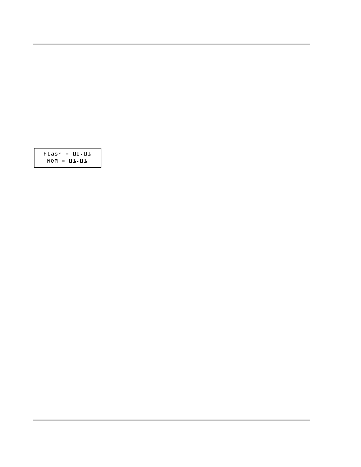
To locate the firmware version number
The firmware version number for the protection processor is visible on a screen that appears when the unit
starts up or is powered up after switching the AC/DC Disconnect switch to “on.” The screen reads:
Flash = 01.01
ROM = 01.01
The number appearing after “ROM” is the firmware version number for the protecti on processor.
FCC Information to the User
This equipment has been tested and found to comply with the limits for a Class B digital device, pursuant
to part 15 of the FCC Rules. These limits are designed to provide reasonable protection against harmful
interference in a residential installation. This equipment generates, uses and can radiate r adio frequency
energy and, if not install ed and used in a ccordance with the in structions , may cause ha rmful inter ferenc e to
radio communications. However, there is no guarantee that interference will not occur in a particular
installati on. I f this equipment does cause harmful interfere nce to radio or television reception, which can
be determined by turning the equipment off and on, the user is encourage d to try to correct the interfe rence
by one or more of the following measures:
• Reorient or relocate the rece iving antenna.
• Increase the separation between the equipment and the receiver.
• Connect the equipment into an outlet on a circ uit different from that to which the re ceiver is connected .
• Consult the dealer or an experie nced r adio/TV technician for help.
viii 975-0131-01-01

Safety
Verification and Commissioning Test
Purpose
This procedure is design ed to verify corr ect operati on of the Xantrex Grid T ie Solar In verter both on initi al
operation and periodically through its life as required by the utilities.
Commissioning Test
Follow the startup and monitoring procedures as documented in Chapters 4 and 5.
When operation of the inverter has been ver ified and the unit is producing power, run the Non-Islanding
test as described in this procedure.
Verification Test
Periodically run the Non-Islanding test. The inverter must respond within the 2-second limit for
compliance and then hold of f on producing power for the required delay (default valu e of 5 minutes) .
Non-Islanding Test
This test requires that the AC circuit for the inverter be switched off. This can be accomplished by
switching the breaker on the main panel that feeds the inverter(s). As an alternate, the disconnect for the
home or business may be used as well. Have someone watch the front panel of the inverter. Within 2
seconds of switching the brea ker, the green light on the front of the inverter must go out. The display will
respond with an AC Fault display, indicating that the AC is out of the operating range.
Re-energi ze the breaker to the inverter. The unit will respond by beginning its countdown. The green light
will be off dur ing this tim e. Five minute s aft er applying AC (default value ), the gr een lig ht will tur n on and
the inverter will beg in to push power to the grid. The display will then retur n to its on-l ine displa y showing
the power being produced along with the tota l kWh produced to date.
Note: The default voltage, frequency and reconnec t delay value s as defined by UL1741 and CSA 107.1-01
are programmed into the unit at time of shipment from the factory. No changes to these settings can be
made in the field by the user. Only authorized personne l with the utility’s permission may change these
settings. Contact Xantrex Technology to gain permission and the procedure/e quipment to make these
changes.
975-0131-01-01 ix

x

Contents
Important Safety In str uctions
Regulatory Compliance - - - - - - - - - - - - - - - - - - - - - - - - - - - - - - - - - - - - - - - - - - - - - - - - - - viii
FCC Information to the User - - - - - - - - - - - - - - - - - - - - - - - - - - - - - - - - - - - - - - - - - - - - - - - viii
Verification and Commissioning Test - - - - - - - - - - - - - - - - - - - - - - - - - - - - - - - - - - - - - - - - - - ix
1
Introduction
About the Xantrex Grid Tie Solar Inverter- - - - - - - - - - - - - - - - - - - - - - - - - - - - - - - - - - - - - 1–2
Standard Features - - - - - - - - - - - - - - - - - - - - - - - - - - - - - - - - - - - - - - - - - - - - - - - - - - - - 1–3
Optional Features - - - - - - - - - - - - - - - - - - - - - - - - - - - - - - - - - - - - - - - - - - - - - - - - - - - - 1–4
Safety and Standards - - - - - - - - - - - - - - - - - - - - - - - - - - - - - - - - - - - - - - - - - - - - - - - - - 1–5
Removable Components- - - - - - - - - - - - - - - - - - - - - - - - - - - - - - - - - - - - - - - - - - - - - - - - - 1–6
Wiring Box (s tan d ard on N o rth Am eri ca n mod e ls) - - - - - - - - - - - - - - - - - - - - - - - - - - - - - 1–6
Optional Heat Sink Cover and Fan - - - - - - - - - - - - - - - - - - - - - - - - - - - - - - - - - - - - - - - - 1–7
Model Configurations - - - - - - - - - - - - - - - - - - - - - - - - - - - - - - - - - - - - - - - - - - - - - - - - - - 1–8
2
Installation
Installation Options - - - - - - - - - - - - - - - - - - - - - - - - - - - - - - - - - - - - - - - - - - - - - - - - - - - - 2–2
Single Inverter Installation - - - - - - - - - - - - - - - - - - - - - - - - - - - - - - - - - - - - - - - - - - - - - - 2–2
Multiple Inverter I nstallations - - - - - - - - - - - - - - - - - - - - - - - - - - - - - - - - - - - - - - - - - - - 2–2
Planning the Installation - - - - - - - - - - - - - - - - - - - - - - - - - - - - - - - - - - - - - - - - - - - - - - - - - 2–2
Inverter Location - - - - - - - - - - - - - - - - - - - - - - - - - - - - - - - - - - - - - - - - - - - - - - - - - - - - 2–4
PV Array Requirements - - - - - - - - - - - - - - - - - - - - - - - - - - - - - - - - - - - - - - - - - - - - - - - 2–5
Grounding Requirements - - - - - - - - - - - - - - - - - - - - - - - - - - - - - - - - - - - - - - - - - - - - - - - 2–8
Routing the Wires - - - - - - - - - - - - - - - - - - - - - - - - - - - - - - - - - - - - - - - - - - - - - - - - - - 2–11
Preparing for the Installation - - - - - - - - - - - - - - - - - - - - - - - - - - - - - - - - - - - - - - - - - - - - - - 2–13
Wiring - - - - - - - - - - - - - - - - - - - - - - - - - - - - - - - - - - - - - - - - - - - - - - - - - - - - - - - - - - 2–13
Circuit Breakers and Disconnect Switch - - - - - - - - - - - - - - - - - - - - - - - - - - - - - - - - - - - 2–13
Other Materials Needed - - - - - - - - - - - - - - - - - - - - - - - - - - - - - - - - - - - - - - - - - - - - - - 2–14
Equipment Needed - - - - - - - - - - - - - - - - - - - - - - - - - - - - - - - - - - - - - - - - - - - - - - - - - - 2–14
Mounting the Inverter - - - - - - - - - - - - - - - - - - - - - - - - - - - - - - - - - - - - - - - - - - - - - - - - - - 2–15
Overview - - - - - - - - - - - - - - - - - - - - - - - - - - - - - - - - - - - - - - - - - - - - - - - - - - - - - - - - 2–15
Preparing to Mount the Unit - - - - - - - - - - - - - - - - - - - - - - - - - - - - - - - - - - - - - - - - - - - - 2–16
Installing the Mounti ng Bracket - - - - - - - - - - - - - - - - - - - - - - - - - - - - - - - - - - - - - - - - - 2–17
Mounting the Inverter on the Bracket - - - - - - - - - - - - - - - - - - - - - - - - - - - - - - - - - - - - - 2–22
Installing Accessories- - - - - - - - - - - - - - - - - - - - - - - - - - - - - - - - - - - - - - - - - - - - - - - - - - - 2–23
975-0131-01-01 xi

Contents
3
Wiring the Inverte r
Accessing the Wiring Terminals - - - - - - - - - - - - - - - - - - - - - - - - - - - - - - - - - - - - - - - - - - - - 3–2
Connecting the DC Wiring- - - - - - - - - - - - - - - - - - - - - - - - - - - - - - - - - - - - - - - - - - - - - - - - 3–4
Connecting the AC Wiring- - - - - - - - - - - - - - - - - - - - - - - - - - - - - - - - - - - - - - - - - - - - - - - - 3–7
Connecting Inverter s in Parallel - - - - - - - - - - - - - - - - - - - - - - - - - - - - - - - - - - - - - - - - - - - 3–10
DC and AC Wiring for Inverters in Parallel - - - - - - - - - - - - - - - - - - - - - - - - - - - - - - - - - -3–10
Communications Wiring for Inverters in Parallel- - - - - - - - - - - - - - - - - - - - - - - - - - - - - - - - 3–12
Xanbus Network Technology - - - - - - - - - - - - - - - - - - - - - - - - - - - - - - - - - - - - - - - - - - -3–12
Guidelines for Routing the Network Cables - - - - - - - - - - - - - - - - - - - - - - - - - - - - - - - - - -3–15
Connect the Communications Cable between Inverters in Parallel - - - - - - - - - - - - - - - - - - -3–16
4
Starting the Inverter
Startup Procedure - - - - - - - - - - - - - - - - - - - - - - - - - - - - - - - - - - - - - - - - - - - - - - - - - - - - - - 4–2
Checking the PV Array DC Voltage - - - - - - - - - - - - - - - - - - - - - - - - - - - - - - - - - - - - - - - 4–2
Checking the AC Utility Voltage - - - - - - - - - - - - - - - - - - - - - - - - - - - - - - - - - - - - - - - - - 4–2
Replacing the Wiring Box Cover - - - - - - - - - - - - - - - - - - - - - - - - - - - - - - - - - - - - - - - - - - - 4–3
Starting up the GT Inverter - - - - - - - - - - - - - - - - - - - - - - - - - - - - - - - - - - - - - - - - - - - - - 4–4
5
Monitoring the Inverter
Monitoring the Front Panel Display- - - - - - - - - - - - - - - - - - - - - - - - - - - - - - - - - - - - - - - - - - 5–2
Front Panel Display Screens and What They Mean - - - - - - - - - - - - - - - - - - - - - - - - - - - - - - - 5–3
Startup Mode - - - - - - - - - - - - - - - - - - - - - - - - - - - - - - - - - - - - - - - - - - - - - - - - - - - - - - 5–3
Normal Operation Mode - - - - - - - - - - - - - - - - - - - - - - - - - - - - - - - - - - - - - - - - - - - - - - 5–3
Offline Mode - - - - - - - - - - - - - - - - - - - - - - - - - - - - - - - - - - - - - - - - - - - - - - - - - - - - - - 5–5
Fault Mode - - - - - - - - - - - - - - - - - - - - - - - - - - - - - - - - - - - - - - - - - - - - - - - - - - - - - - - - 5–6
Special Screens - - - - - - - - - - - - - - - - - - - - - - - - - - - - - - - - - - - - - - - - - - - - - - - - - - - - - 5–8
Custom Screens - - - - - - - - - - - - - - - - - - - - - - - - - - - - - - - - - - - - - - - - - - - - - - - - - - - - 5–9
Status Indicator Lights- - - - - - - - - - - - - - - - - - - - - - - - - - - - - - - - - - - - - - - - - - - - - - - - - - - 5–9
6
Maintenance and Troubleshooting
Factors Affecting GT Inverter Performance - - - - - - - - - - - - - - - - - - - - - - - - - - - - - - - - - - - - 6–2
PV Array Factors - - - - - - - - - - - - - - - - - - - - - - - - - - - - - - - - - - - - - - - - - - - - - - - - - - - 6–2
Other Factors - - - - - - - - - - - - - - - - - - - - - - - - - - - - - - - - - - - - - - - - - - - - - - - - - - - - - - 6–3
Performing General Maintenance - - - - - - - - - - - - - - - - - - - - - - - - - - - - - - - - - - - - - - - - - - - 6–3
Replacing Parts - - - - - - - - - - - - - - - - - - - - - - - - - - - - - - - - - - - - - - - - - - - - - - - - - - - - - - - 6–3
Replacing the Ground Fault Prot ection Fuse - - - - - - - - - - - - - - - - - - - - - - - - - - - - - - - - - 6–4
Replacing the Inverter - - - - - - - - - - - - - - - - - - - - - - - - - - - - - - - - - - - - - - - - - - - - - - - - 6–5
Identifying Error /Fault Conditions and Solutions- - - - - - - - - - - - - - - - - - - - - - - - - - - - - - - - - 6–8
xii 975-0131-01-01

A
Specifications
Electrical Specifications - - - - - - - - - - - - - - - - - - - - - - - - - - - - - - - - - - - - - - - - - - - - - - - - - A–2
Input - - - - - - - - - - - - - - - - - - - - - - - - - - - - - - - - - - - - - - - - - - - - - - - - - - - - - - - - - - - -A–2
Output - - - - - - - - - - - - - - - - - - - - - - - - - - - - - - - - - - - - - - - - - - - - - - - - - - - - - - - - - - -A–2
Adjustable disconne ct settings - - - - - - - - - - - - - - - - - - - - - - - - - - - - - - - - - - - - - - - - - - -A–3
Efficiency - - - - - - - - - - - - - - - - - - - - - - - - - - - - - - - - - - - - - - - - - - - - - - - - - - - - - - - - -A–4
Environmental Specifications - - - - - - - - - - - - - - - - - - - - - - - - - - - - - - - - - - - - - - - - - - - - - A–5
User Display - - - - - - - - - - - - - - - - - - - - - - - - - - - - - - - - - - - - - - - - - - - - - - - - - - - - - - -A–5
Mechanical Specifications - - - - - - - - - - - - - - - - - - - - - - - - - - - - - - - - - - - - - - - - - - - - - - - A–5
Accessories - - - - - - - - - - - - - - - - - - - - - - - - - - - - - - - - - - - - - - - - - - - - - - - - - - - - - - - - - A–6
Warranty and Return Information
Warranty - - - - - - - - - - - - - - - - - - - - - - - - - - - - - - - - - - - - - - - - - - - - - - - - - - - - - - - - - WA–1
Disclaimer - - - - - - - - - - - - - - - - - - - - - - - - - - - - - - - - - - - - - - - - - - - - - - - - - - - - - - - - WA–2
Return Material Authorization Policy - - - - - - - - - - - - - - - - - - - - - - - - - - - - - - - - - - - - - - WA–3
Return Procedure- - - - - - - - - - - - - - - - - - - - - - - - - - - - - - - - - - - - - - - - - - - - - - - - - - - - WA–3
Out of Warranty Service- - - - - - - - - - - - - - - - - - - - - - - - - - - - - - - - - - - - - - - - - - - - - - - WA–3
Information About Your System - - - - - - - - - - - - - - - - - - - - - - - - - - - - - - - - - - - - - - - - - WA–4
Contents
Index
975-0131-01-01 xiii

xiv

Figures
Figure 1-1 Basic System Overview - - - - - - - - - - - - - - - - - - - - - - - - - - - - - - - - - - - - - - - - - - - - 1–2
Figure 1-2 Main Features of the GT Inverter- - - - - - - - - - - - - - - - - - - - - - - - - - - - - - - - - - - - - - 1–4
Figure 1-3 Safety and Data Label Locations - - - - - - - - - - - - - - - - - - - - - - - - - - - - - - - - - - - - - - 1–5
Figure 1-4 Wiring Box for the GT Inverter - - - - - - - - - - - - - - - - - - - - - - - - - - - - - - - - - - - - - - - 1–6
Figure 1-5 Optional Heat Sink Cover and Fan Assembly for the GT Inverter- - - - - - - - - - - - - - - - 1–7
Figure 2-1 Installation Options Overview- - - - - - - - - - - - - - - - - - - - - - - - - - - - - - - - - - - - - - - - 2–3
Figure 2-2 Basic Grounding Overview- - - - - - - - - - - - - - - - - - - - - - - - - - - - - - - - - - - - - - - - - - 2–9
Figure 2-3 Long Distance Grounding Overview - - - - - - - - - - - - - - - - - - - - - - - - - - - - - - - - - - 2–10
Figure 2-4 Grounding With Extra Lightning Protection Overview - - - - - - - - - - - - - - - - - - - - - - 2–11
Figure 2-5 Knockout Locations on Bottom of Wiring Box - - - - - - - - - - - - - - - - - - - - - - - - - - - 2–12
Figure 2-6 Installation Overview- - - - - - - - - - - - - - - - - - - - - - - - - - - - - - - - - - - - - - - - - - - - - 2–15
Figure 2-7 Dimensions of GT Inverter and Knockout Locations- - - - - - - - - - - - - - - - - - - - - - - - 2–17
Figure 2-8 Mou nt i ng Br ack et an d GT In v erter - - - - - - - - - - - - - - - - - - - - - - - - - - - - - - - - - - - 2–18
Figure 2-9 Examples of Mounting on a Pole or Rails - - - - - - - - - - - - - - - - - - - - - - - - - - - - - - - 2–20
Figure 2-10 Installing the Mounting Bracket using Plywood Support - - - - - - - - - - - - - - - - - - - - - 2–21
Figure 2-11 Proper Placement of the Inverter on the Mounting Bracket - - - - - - - - - - - - - - - - - - - 2–22
Figure 2-12 Attaching the fan assembly- - - - - - - - - - - - - - - - - - - - - - - - - - - - - - - - - - - - - - - - - 2–24
Figure 2-13 Location of Fan Connector - - - - - - - - - - - - - - - - - - - - - - - - - - - - - - - - - - - - - - - - - 2–25
Figure 3-1 Removing the Wiring Box Cover- - - - - - - - - - - - - - - - - - - - - - - - - - - - - - - - - - - - - - 3–2
Figure 3-2 AC and DC Terminal Block Location in the Wiring Box- - - - - - - - - - - - - - - - - - - - - - 3–3
Figure 3-3 AC/DC Disconnect Switch Positions - - - - - - - - - - - - - - - - - - - - - - - - - - - - - - - - - - - 3–4
Figure 3-4 DC Connections for Grounded PV Array - - - - - - - - - - - - - - - - - - - - - - - - - - - - - - - - 3–6
Figure 3-5 AC Connections from GT Inverter to Utility Service Panel - - - - - - - - - - - - - - - - - - - - 3–9
Figure 3-6 Parallel GT Inverter DC and AC Wiring - - - - - - - - - - - - - - - - - - - - - - - - - - - - - - - - 3–11
Figure 3-7 Daisy Chain Layout- - - - - - - - - - - - - - - - - - - - - - - - - - - - - - - - - - - - - - - - - - - - - - 3–12
Figure 3-8 Male Network Terminator - - - - - - - - - - - - - - - - - - - - - - - - - - - - - - - - - - - - - - - - - 3–13
Figure 3-9 Xanbus RJ45 Ports in the GT Inverter Wiring Box- - - - - - - - - - - - - - - - - - - - - - - - - 3–13
Figure 3-10 RJ45 Connector - - - - - - - - - - - - - - - - - - - - - - - - - - - - - - - - - - - - - - - - - - - - - - - - 3–14
Figure 3-11 Communications Wiring for GT Inverters in Parallel - - - - - - - - - - - - - - - - - - - - - - - 3–17
Figure 4-1 AC/DC Disconnect Switch Positions - - - - - - - - - - - - - - - - - - - - - - - - - - - - - - - - - - - 4–4
Figure 5-1 Front Panel LCD Location - - - - - - - - - - - - - - - - - - - - - - - - - - - - - - - - - - - - - - - - - - 5–2
Figure 5-2 Lo cati o n of Stat us Ind i cato r L ight s - - - - - - - - - - - - - - - - - - - - - - - - - - - - - - - - - - - 5–10
Figure 6-1 Location of Fuse, Front Panel Cover Removed - - - - - - - - - - - - - - - - - - - - - - - - - - - - 6–5
Figure 6-2 Inverter and Wiring Box Sections - - - - - - - - - - - - - - - - - - - - - - - - - - - - - - - - - - - - - 6–7
Figure A-1 Output Power vs. Ambient Temperature - - - - - - - - - - - - - - - - - - - - - - - - - - - - - - - - -A–3
Figure A-2 Typical Efficiency- - - - - - - - - - - - - - - - - - - - - - - - - - - - - - - - - - - - - - - - - - - - - - - -A–4
975-0131-01-01 xv

xvi

Tables
Table 1-1 GT Inverter Models- - - - - - - - - - - - - - - - - - - - - - - - - - - - - - - - - - - - - - - - - - - - - - - 1–8
Table 2-1 MPPT Operational Window - - - - - - - - - - - - - - - - - - - - - - - - - - - - - - - - - - - - - - - - - 2–6
Table 2-2 Inverter Clearance Requirements - - - - - - - - - - - - - - - - - - - - - - - - - - - - - - - - - - - - - 2–18
Table 3-1 Torque Values for Wires* - - - - - - - - - - - - - - - - - - - - - - - - - - - - - - - - - - - - - - - - - - 3–5
Table 3-2 T568A Standard Wiring - - - - - - - - - - - - - - - - - - - - - - - - - - - - - - - - - - - - - - - - - - - 3–14
Table 3-3 Network Components and Part Numbers- - - - - - - - - - - - - - - - - - - - - - - - - - - - - - - - 3–15
Table 5-1 Startup Screens on GT Inverter Front Panel Display - - - - - - - - - - - - - - - - - - - - - - - - - 5–3
Table 5-2 Normal Operation Default Screen - - - - - - - - - - - - - - - - - - - - - - - - - - - - - - - - - - - - - 5–4
Table 5-3 Normal Operation Screens for All GT Inverter Units - - - - - - - - - - - - - - - - - - - - - - - - 5–4
Table 5-4 Additional Normal Operation Screens for Each GT Inverter Unit
in a Multiple Unit System- - - - - - - - - - - - - - - - - - - - - - - - - - - - - - - - - - - - - - - - - - - 5–5
Table 5-5 Offline Mode Default Display- - - - - - - - - - - - - - - - - - - - - - - - - - - - - - - - - - - - - - - - 5–5
Table 5-6 Offline Mode Screens for All GT Inverter Units- - - - - - - - - - - - - - - - - - - - - - - - - - - - 5–6
Table 5-7 Additional Of fline Mode Screens for Each GT Inverter Unit in a Multiple Unit System - 5–6
Table 5-8 Fault Message Screens- - - - - - - - - - - - - - - - - - - - - - - - - - - - - - - - - - - - - - - - - - - - - 5–7
Table 5-9 Additional Fault Mode Screens - - - - - - - - - - - - - - - - - - - - - - - - - - - - - - - - - - - - - - - 5–8
Table 5-10 Special Message Screens - - - - - - - - - - - - - - - - - - - - - - - - - - - - - - - - - - - - - - - - - - - 5–8
Table 5-11 Status Indicator LEDs - - - - - - - - - - - - - - - - - - - - - - - - - - - - - - - - - - - - - - - - - - - - - 5–9
Table 6-1 Troublesh ooting the GT Inverter - - - - - - - - - - - - - - - - - - - - - - - - - - - - - - - - - - - - - - 6–8
975-0131-01-01 xvii

xviii

1
Introduction
Chapter 1, “Introduction”, contains information about the features
and functions of the Xantrex Grid Tie Solar Inverter.
The topics in this chapter are organized as follows.
“About the Xantrex Grid Tie Solar Inverter”:
•“S tandard Features” on page 1–3
•“Safety and St andards” on page 1–5
“Removable Components”:
•“Wiring Box (standard on North American models)” on page 1–6
•“Optional Heat Sink Cover and Fan” on page 1–7.
“Model Configurations”.
Introduction
About the Xantrex Grid Tie Solar Inverter
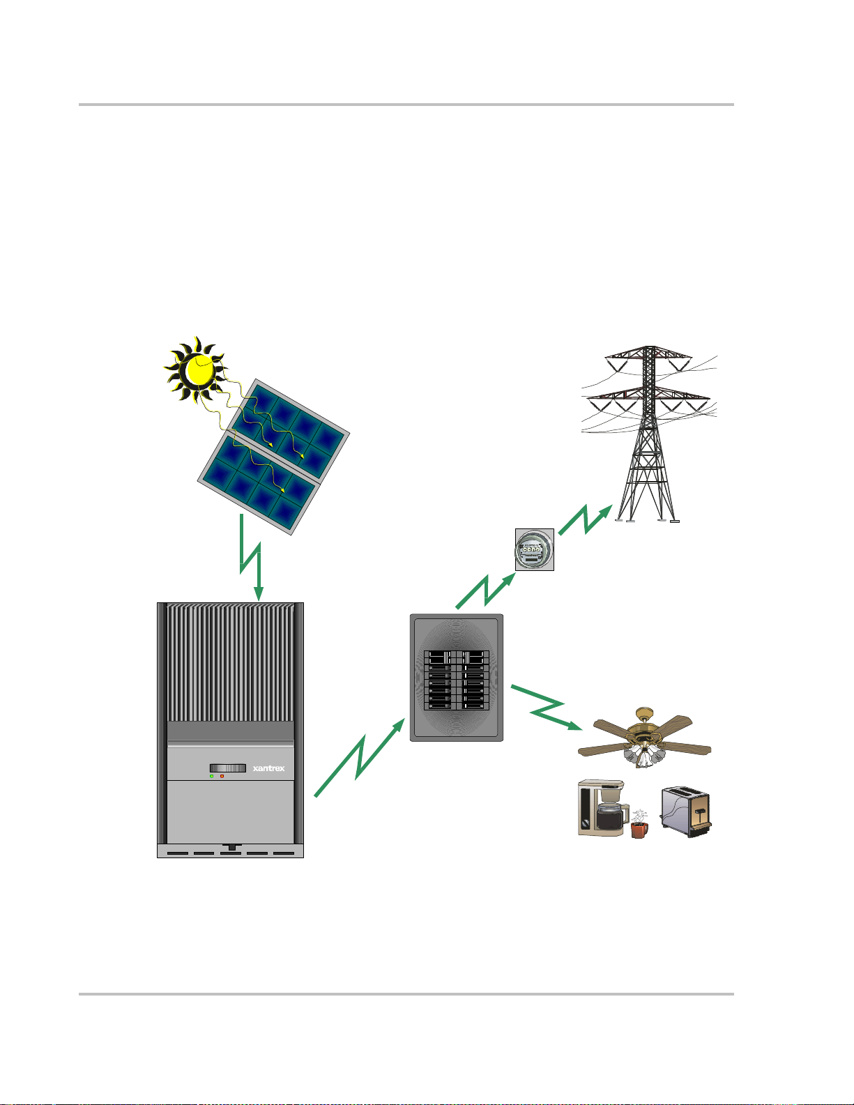
The Xantrex Grid Tie Solar Inver ter (GT Inverter) is designed to convert solar
electric (photo voltaic or PV) power into utility-grade elec tricity that can be used
by the home or sold to the local power company.
Installing the GT Inverter consists of mounting it to the wall and connecting the
DC input to a PV array and the AC output to the utility. See Figure 1-1 for a
simple diagram of a typical inst allation.
In order t o opera te, t he GT Inverter must have gri d power a vaila ble and co nnected.
It will not provide backup power if the AC grid fails.
Photo voltaic (PV)
Panels - PV Array
Harvested
solar energy
Grid Tie Inverter
Figure 1-1 Basic System Overview
DC converted
to AC
Xantrex
GT Inverter
Utility
Meter
Utility Grid
Surplus powe r
rout ed to U tility Grid
Powe r route d
to loads
Main Utility
Service Panel
Loads
1–2 975-0131-01-01
About the Xantrex Grid Tie Solar Inverter
PV compatibility The G T I nverter is de signed t o take advanta ge of solar mo dules c onfigure d as hi gh
voltage PV string arrays—single crystalli ne , poly crystall ine, or thin film—with a
195 to 550 Vdc input voltage Maximum Power Point range.
Maxi mum Power
Point Tracking
(MPPT)
The GT Inverter uses Xantrex pr opr ietary Maximum Power Point Tracking
(MPP T) technology to harvest the maximum amount of energy from the solar
array. MPPT learns your array ’s specific char acteristics, ma xim i zin g its outp u t at
all times.
High efficiency The high-frequency, solid-state design of the GT Inverter is extremely efficient—
up to 95%.
Expandable Multiple GT Inverters may be connected in a parallel configuration for increased
net metering capacity or future system growth.
®
Communications
protocol
The GT Inverter uses the Xanbus
communi cate w i th othe r uni ts co nn ected in p ara llel with in the sys tem . Fo r more
Communications protocol, enabling it to
information, see “Xanbus Network Technology” on page 3–12.
Standard Features
The GT Inverter has the following standard features:
• Sealed inverter sect ion with multiple wiring options to facili tate a variety of
installati on requir ements ( e.g., h ard-wir ed, “quick-connects,” wiring box wi th
terminals, or with AC/DC disconnect);
• LCD providing easy-to-read system status and daily cumulative energy
production information;
• Two LED indicator lights providing status and ground fault indication;
• Wiring box providing protection for all AC and DC connections and
eliminating exposed “live” wiring if the inverter is removed.
WARNING: Shock hazard
The 600 volt DC/AC disconnect in the wiring box meets NEC Article 690. It is a nonserviceable component and shall rem ain in place. Removal can exp ose energized
conductors.
975-0131-01-01 1–3
Introduction
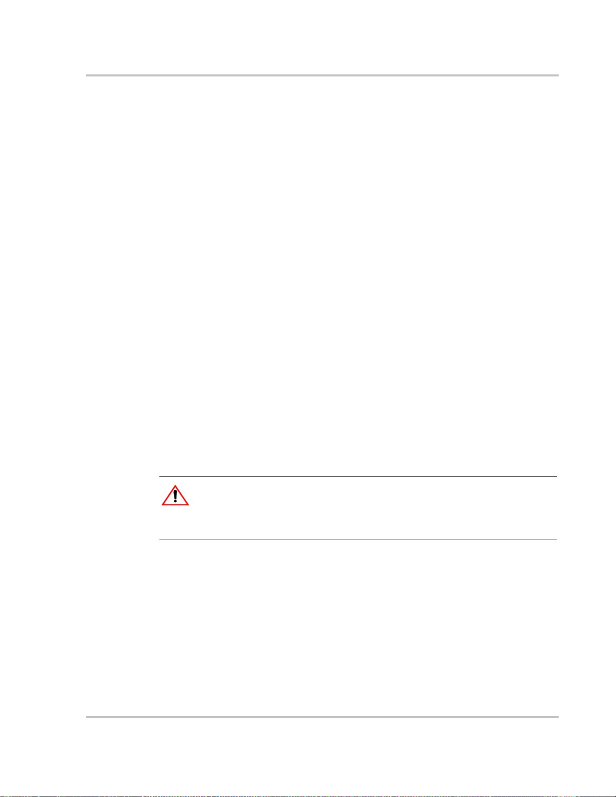
Optional Features
GT Fan Kit (Xantrex part # 864-0201) includes:
• Heat sink cover
• Fan assembly.
Xantrex GT3.0 Inverter
Heat Sink
Optional Heat Sink cover
LCD
Figure 1-2
LED Indicator Light s
Wiring Box
AC/DC Disconnect Switch
Mounting Slots
Main Features of the GT Inverter
1–4 975-0131-01-01
Safety and Standards
About the Xantrex Grid Tie Solar Inverter
Meets standards and
requirements
The GT Inverter has complete on-board over-current, over-temperature and antiislanding protec tion, and meets U.S., Canadian and internationa l safety operating
standards and code requirements:
• UL 1741 – Standard for Inverters, Converters, and Controllers for Use in
Independent Power Systems
• CSA C22.2 No. 107.1-01 General Use Power Supplies.
Safety Label
Location
Data Label
Location
Figure 1-3
Safety and Data Label Locations
Figure 1-3 shows the location of the safety la be l and the data label with model,
serial and part num b er i nfo rma t ion.
975-0131-01-01 1–5
Introduction
Removab le Compo ne n ts
The wiring box is standard for all North Ameri can models of the G T Inverter.
Some European models are available without the wiring box. See “Model
Configurations” on page 1–8 for specific details. The heat sink cover and fan
assembly are available in the optional Fan Kit.
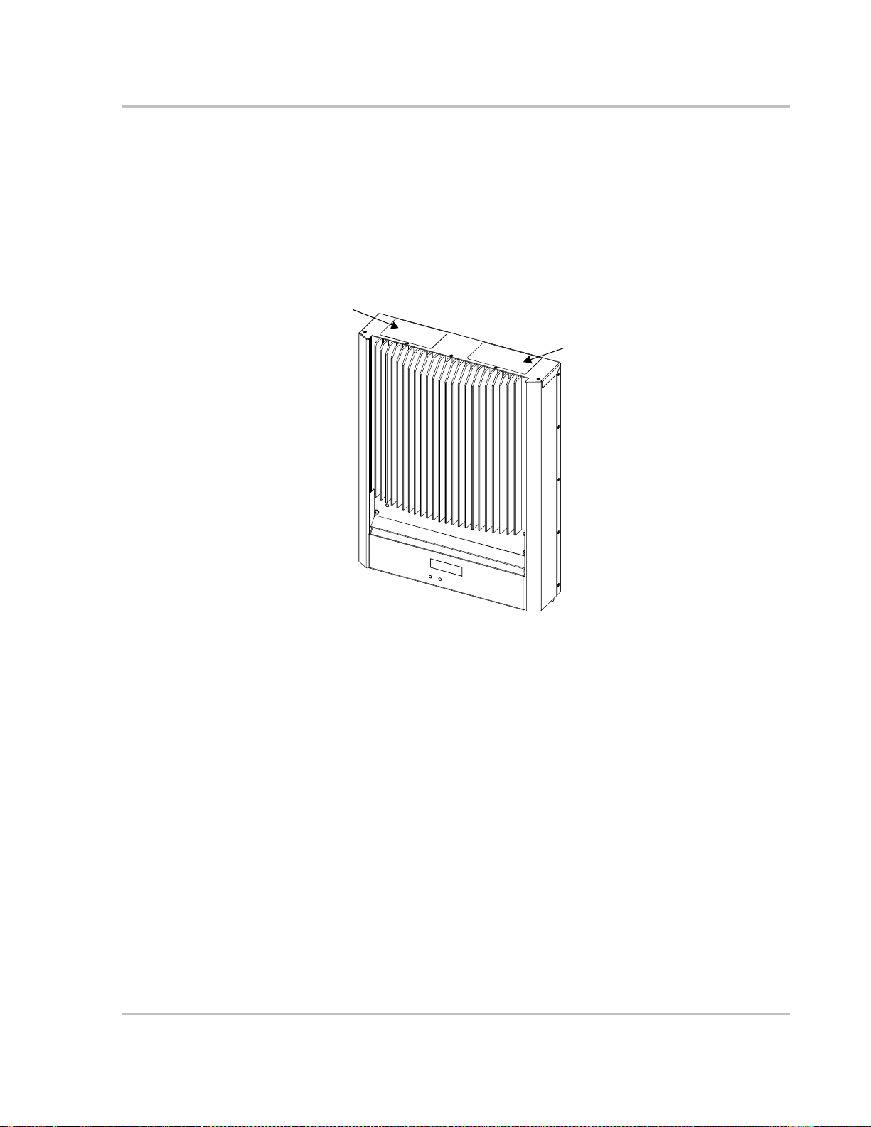
Wiring Box (st andard on North American models)
The wiring box provides a location fo r making AC, DC and ground connections.
It also contains the combine d AC/DC (Utility/PV array) Disconnect Switch.
The GT Inverter unit may be easily remove d from the wiring box in the event that
the inverter requir es servicing.
Important:
requirement. It must be attached during operation. Che ck with your local authorities
before removing the GT Inverter wiring box.
DC Connect holes
AC/DC Disconnect
Switch
Figure 1-4
In North America and other locations the wiring box is an electrical code
Control Board
Connect hole
AC Connect hole
Wiring Box
Front Cover
1.9 cm (3/4”) Threaded
Conduit holes
Wiring Box for the GT Inverter
1–6 975-0131-01-01
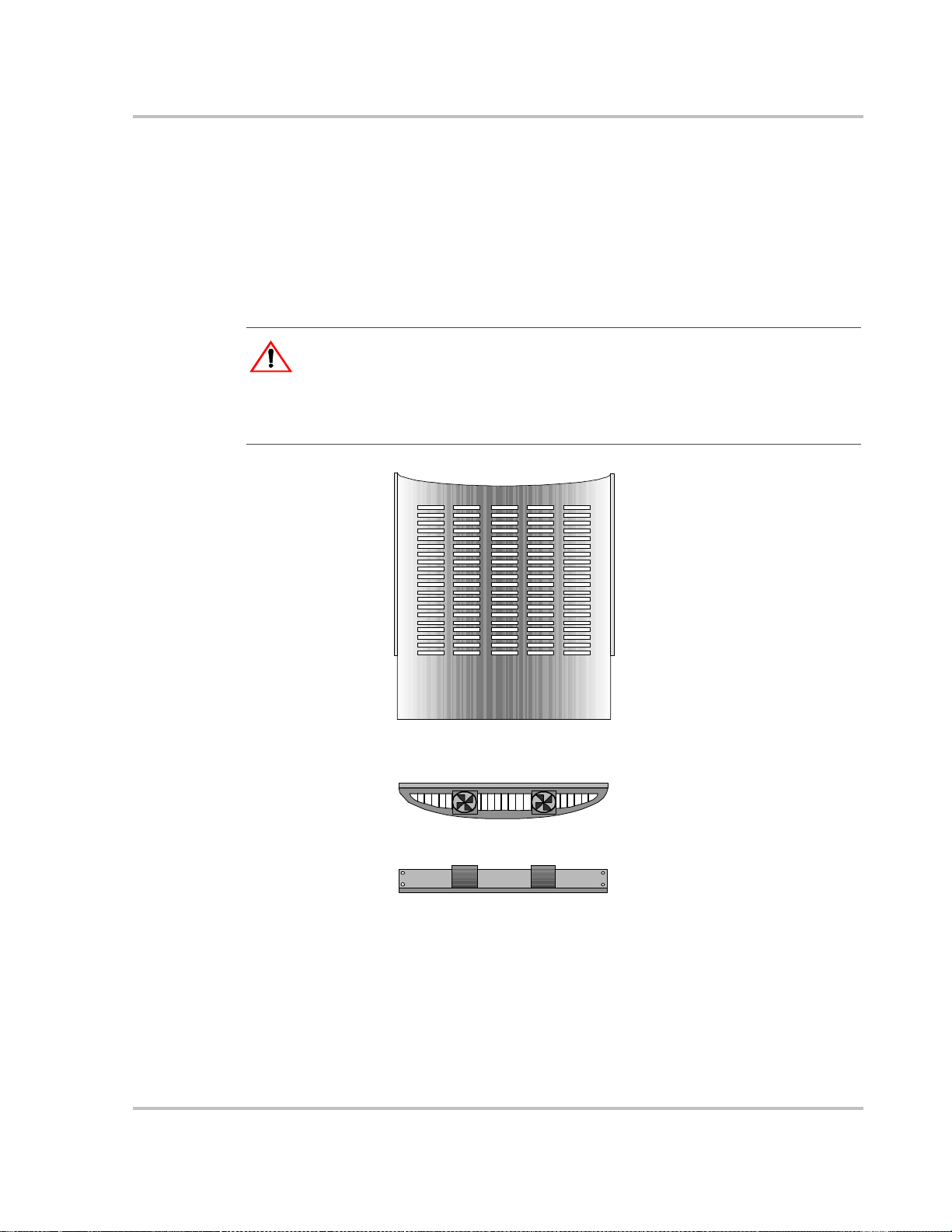
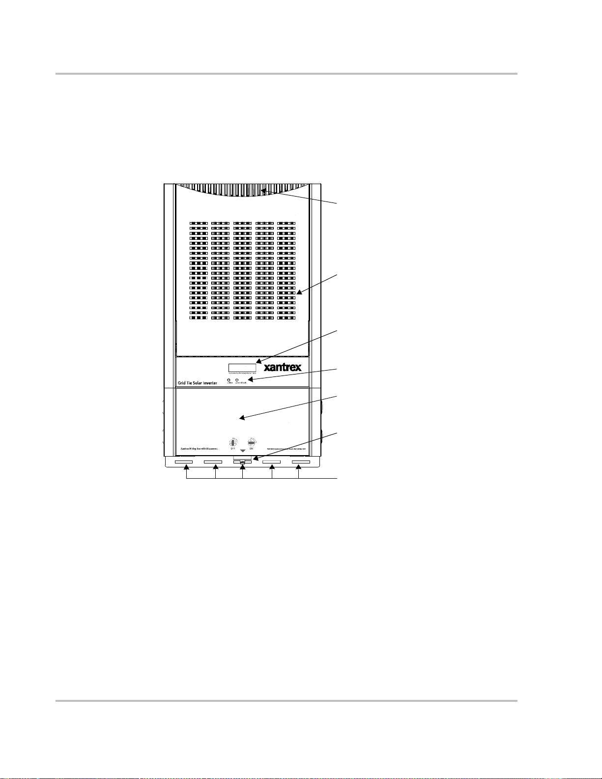
Optional Heat Sink Cover and Fan
In areas where high ambient temperatures (>45°C/110°F) may be experienced
(such a south-fa cing install at ion), a he at sink cove r and fan ass embly (GT Fan Kit,
Xantrex part # 864-0201) can be added to the front of the unit. The fan assembly
provides forced-a ir ventilation directly over the heat sink. The heat sink cover
shades the heat sink from direct sunlight and provides a pathway to funnel the
forced-air from the fans over the heat sink to optimize cooling.
WARNING: Burn hazard
In ext reme cond itions, the GT Inverter chassis can reach temperatures over 70°C (158°F),
which can cause skin burns if accidentally touched. Ensure that the GT Inverter is located
away fro m normal t raffic areas.
See Figure 1-3 on page 1–5 for safety label loc ati on.
Removable Components
Heat Sink Cover
Top view
Fan Assembly
Front view
Figure 1-5
975-0131-01-01 1–7
Optional Heat Sink Cove r and Fan Assembly for the GT Inve rter
Introduction
Model Configu rations
The GT Inverter model number is in the format GTx.x-aa-bb-ccc, where:
• x.x Output Power: 3.0 KW
• aa Region: NA (N ort h Am eri ca)
• bb Wiring Box: WB (wiring box only)
• ccc Output Voltage: 208 Vac/60 Hz (North America) 3 phase
See Figure 1-3 on page 1–5 for data label location.
DE (Germany)
SP (Spain)
IT (Italy)
FR (France)
DS (wiring box with AC/DC disconnect switch)
HW (no wiring box)
QC (Quick Connects and no wiring box , Europe
only, not available at this time)
230 Vac/50 Hz (Europe) 3 phase
240 Vac/60 Hz (North America).
T able 1-1 shows the different model conf igurations available.
Table 1-1
Model Number
GT3.0-NA-bb-208
GT3.0-aa2-bb-230
GT3.0-NA-bb-240
1. 208 Vac/60 Hz and 230 Vac/50 Hz models not available at this time
2. any region (aa) exce pt NA
GT Inverter Models
Output
Power
(x.x)
1
1
3.0
Output
Voltage
(ccc)
208
230
240
Wiring Box (bb)
WB DS HW QC
√√√
√√√√
√
Installation and wiring instructions are provided in Chapter 2, “Installation”, and
Chapter 3, “Wiring the Inverter”.
1–8 975-0131-01-01

2
Installation
Chapter 2, “Installation”, provides information about planning for and
installing the GT Inverter. It contains information to help you plan
wire routes, AC and DC connections, and find a suitable location for
installation. It also discusses requirements for grounding the GT
Inverter and your PVarray.
Procedures are provided for installing the Xantrex Grid Tie Solar
Inverter.
The topics in this chapter are organized as follows:
•“Ins talla tion Options” on page 2–2
•“Planning the Installation” on page 2–2
•“Pr ep aring for the Insta llation ” on page 2–13
•“Mounting the Inverter” on page 2–15
•“Installing Accessories” on page 2–23.

Installation
Installation Options
The GT Inverter may be installed as a single inverter for a single PV array of one
or two PV strings, or in a multiple inverter configuration for multiple PV arrays
(see Figure 2-1 for diagrams of both options) .
Single Inverter Installation
In this configuration, a single inverter collects the harve sted solar energy and
routes the power to the main utilit y servic e panel to be used by the loads. Any
surplus power not used by the loads will be injected into the utility grid.
Multiple Inv erter Installations
If multiple inverters are use d, each inverter must be wired to an independent PV
array. In this configuration, each inverter collects the harvested solar energy from
a separate PV array and routes the power to the main utility service panel to be
used by the loads. Any surplus power not used by the loads will be injected into
the utility grid.
Communications between inverters is optional, but can be enabled by installing
communications cabling to the inverter RJ45 ports. See “Connect the
Communications Cable between In verte rs in Parallel” on page 3–16.
Planning the Installation
The following issues need to be considered when planning for an installation
using the GT Inverter. See the specified sections for more inform ation.
•“Inverter Location” on page 2–4
•“PV Array Requirements” on page 2–5
•“Grounding Requirements” on page 2–8
•“Routing the Wire s” on page 2–11.
Ensure that you have obtained all permits required by local authorities or utilities
before commencing instal lation.
2–2 975-0131-01-01

Single Inverter Installation
Planning the Installation
Utility Grid
Photovoltaic Panels - PV Array
PV String # 1
PV String # 2
#2
PV Array #1
Harvested solar energy
Multiple Inverter Insta llation
Xantrex
GT Inverter
Grid Tie Inverter
DC
converted
to AC
Main Utility
Service Pan el
Utility
Meter
Surplus pow er
routed to Utility Grid
Loads
Powe r ro ute d
to lo ads
Utility Grid
Utility
Meter
Power route d
to loads
Surplus power
route d to Utilit y Grid
Loads
Phot ovoltaic Panels:
Multiple PV Arrays
Figure 2-1
solar energy
Harvested
solar energy
PV Array #2
Harvested
#1
Xantrex GT Inverters
GT Inverter #1
Installation Options Overview
Grid Tie InverterGrid Tie Inverter
GT Inverter #2
DC converted to AC
DC
converted
to AC
Main Utility
Service Panel
975-0131-01-01 2–3

Installation
Inverter Location
WARNING: Burn hazard
Do not in stall in a location where pe ople can accide ntally come into contact wi th the front
of the inverter. High temperatures can be present on the face of the inverter, causing a
potential burn hazard.
In ext reme cond itions, the GT Inverter chassis can reach temperatures over 70°C (158°F),
which can cause skin burns if accidentally touched. Ensure that the GT Inverter is located
away fro m normal t raffic areas.
Inverter failure due to improper installation will void the inverter warranty.
Consider the following when dete rmining where to install the inverter.
Fire Safety
Indoor/Outdoor
Orientation
Temperature
Ground
Clearance
Distance
• Do not install anywhere near combustible or flammable materials.
• The GT Inverter uses a Type 3R-rated enclosure (ve rtical moun t
only) that can be mounted indoors or outdoors. (Type 3R
enclosures are intended for outdoor use primarily to provide a
degree of protection against falling rain; and to be undamaged by
the formation of ice on the enclosure.)
• While t h e 3 R-rated enclosu r e p rotects th e GT Inverter from
moisture, outdoor installations should be located away from lawn
sprinklers and other sources of spray.
• The GT Inverter must be mounted vertically on a wall or pole.
• Do not mount the GT Inverter horizontally.
• Ensure that the GT Inverter is mounted in a location where the
ambient te mperatur e range is
• At extreme hot or cold temperatures, the front panel LCD may not
function normally. Above 45° C (113° F), the unit begins derating
power . See “Environmental Specifications” on page A–5 and
“Output Power vs. Ambient Temperature” on pag e A–3.
• Outdoors, the GT Inverter requires at least 100 cm (39 inches) of
clearance between the bottom of the unit and the ground.
• Indoors, it is recommended that the same clearance between the
bottom of the unit and the floor be used.
• To minimize copper losses, ensure that wire lengths between the
PV array a n d t h e GT Inverter an d b etw een the inverter and t h e
Main Utility Service Panel are kept to a minimum.
• Maximum distances will depend on wire gauges used and PV
array output voltages.
-25° to +65° C (-13° to +149° F).
Debris free
2–4 975-0131-01-01
• Excessive debris (e.g., dust, leaves, cobwebs) can accumulate on
the unit, interfering with wiring connections and ventilation. Do
not install in a location where debris can accu mul ate (such as
under a tree).

PV Array Requirements
WARNING: Shock hazard
Whenever a PV array is exposed to sunlight, a shock hazard exists at the output wires or
exposed terminals. To reduce the risk of s hock during installation, cover the a rray with an
opaque (dark) material before making any connections.
General Recommendations
It is important that the PV array is installed correctly to the manufacturer’s
specifications and to local code requirements.
For general recommendations on PV array installation, the CEC Guide to
Photovoltaic System Design and Installation document referenced in “Related
Information” on page v is recommended. It is available at www.energy.ca.gov.
Equipment and Installation Recommendations
The following PV array equipment and installation recommendations are taken
from the CEC Guide to Photovoltaic System Desig n and Insta llation document
referred to above.
Planning the Installation
Equipment
recommendations
Installation
recommendations
Important:
requirement inc ludes even small obstructi ons such as vent pipes, chimneys and power
lines. A small amount of shade can have a disproportionately high impact on system
performance.
• All electric al equipment should be listed for the voltage and current ratings
necessary for the application.
• All wiring should be sized correctly to minimize voltage drop.
• All exposed wires or conduits shou ld be sunlight resistant.
• All required overcurrent protections should be included in the system and
accessible fo r ma int enan c e.
• Depending on the installation, an external disconnect may be required if the
inverter is installe d in a location not easily accessible to util ity or fire
personnel. Consult local authorities for additional information.
• Integral roofing products should be properly rated.
• All electrical ter minations should be fully tightened, secured, and strain
relieved as appropriate.
• All mounting equipment should be insta lled according to the manufacturer’s
specifications.
• All roof penetrat ions should be sealed with an acceptable sealing method that
does not adversely impact the roo f warra nty.
• All wires, conduit , exposed c onductor s and ele ctri cal boxes s hould be sec ured
and supported according to cod e requirements.
The PV array should be free of shade between 9:00AM and 4:00 PM. This
975-0131-01-01 2–5

Installation
Voltage and MPPT Requirements
MPPT ope rational
window
Voltage
requirements
Ensure that the PV array used in the system operates within the MPPT operational
window (Table 2-1).
Table 2-1
Voltage Effect of Array Voltage Inverter Mode
< 195 Vdc Operating voltage will be shifted to 195 Vdc;
195 to 550 Vdc Maxi mum harvest of solar energy MPPT window
550 to 600 Vdc Will not allow maximum harvest of solar
> 600 Will shut down and may cause damage to the
MPPT Operational Window
Low power
the array will not be at its maximum power
point
Power derating
energy
Shutdown
inverter; stops selling surplus energy
The maximum power point volt age o f a str ing conne cted to the GT Inverter should
be a minimum of 195 Vdc. If it is less than 195 Vdc, then the power point is
shifted and the PV voltage is regulated to 195 Vdc.
By regulating the operati ng voltage of the solar modules, the MPPT software
maximizes their output energy.
Effects of arr ay voltages outside of the MPPT ope rational window are shown in
Table 2-1.
Maxi mum PV
Power
The solar array should be sized such that its maximum power output does not
exceed the limits of the MPPT operational window (195 to 550 Vdc). See
“Guidelines for Matching PV Array Size to Xantrex Grid Tie Solar Inverter
Input”.
Under no conditions should the arra y voltage exceed 600 V
(open circuit
OC
voltage).
2–6 975-0131-01-01

Planning the Installation
Guidelines for Matching PV Array Size to Xantrex Grid Tie Solar Inverter Input
For determinin g the number of panels r equired in the PV string (panels connecte d
in series), you must ensure that the following two requirements are met:
1. To avoid damage to the inverter, ensure that the PV array output will never
exceed 600 Vdc under any conditions.
2. To achieve maximum energy harvest fr om your array, ensure that the V
(voltage at maximum power) doe s not drop below 195 Vdc or increase above
550 Vdc under most conditions.
Guidelines to help you meet these requirements:
MP
• Consider the expected V
panel manufacturer provid es a V
of the string under all possible condit ions. The
OC
rating per panel, but it is usually rat ed at
OC
25°C (77°F). Pane l voltage increases in cold temperatures—the panel
manufacturer shoul d be able to provide a coefficient of voltage inc rease per
degree.
• The NEC also has required temperature/voltage deratings that must be used;
these can be found in Table 690.7 of the 2002 NEC handbook. Y ou need to
determine the coldest temperatures expected on the site, and size the array
strings accordingly. The array’s maximum DC voltage in col dest expected
temperature, with both manufacturer coeffici ent and NEC derating, must not
exceed 600 Vdc to prevent inverter damage.
• Panel voltage decreas es in high temperatures. This will affect the panels’
VMP. Again, the man ufact u re r ’s coefficient must be used with the highest
expe cted temperature to determine the minimum V
MP
.
Once you know the specification s of your panels, all these factors will help
determine the maximum and minimum number of panels that can be used.
Visit www.xantrex.com/support to use an online PV array sizing tool.
975-0131-01-01 2–7

Installation
Grounding Requirements
WARNING: Shock hazard
The GT Inverter must be grounded by connection to a grounded permanent wiring system.
AC Grounding
North America The GT Inverter must be connected to a grounded, permanent wiring system.
The negative PV conductor must be bonded to the grounding system at only one
point in the system, through the internal Ground Fault Detection circuit.
See Figure 2-2 for the location of the GT Inverter ground bar .
Elsewhere In other locations, AC grounding is governed by local codes. Consult with the
local utility for specific grounding requirements.
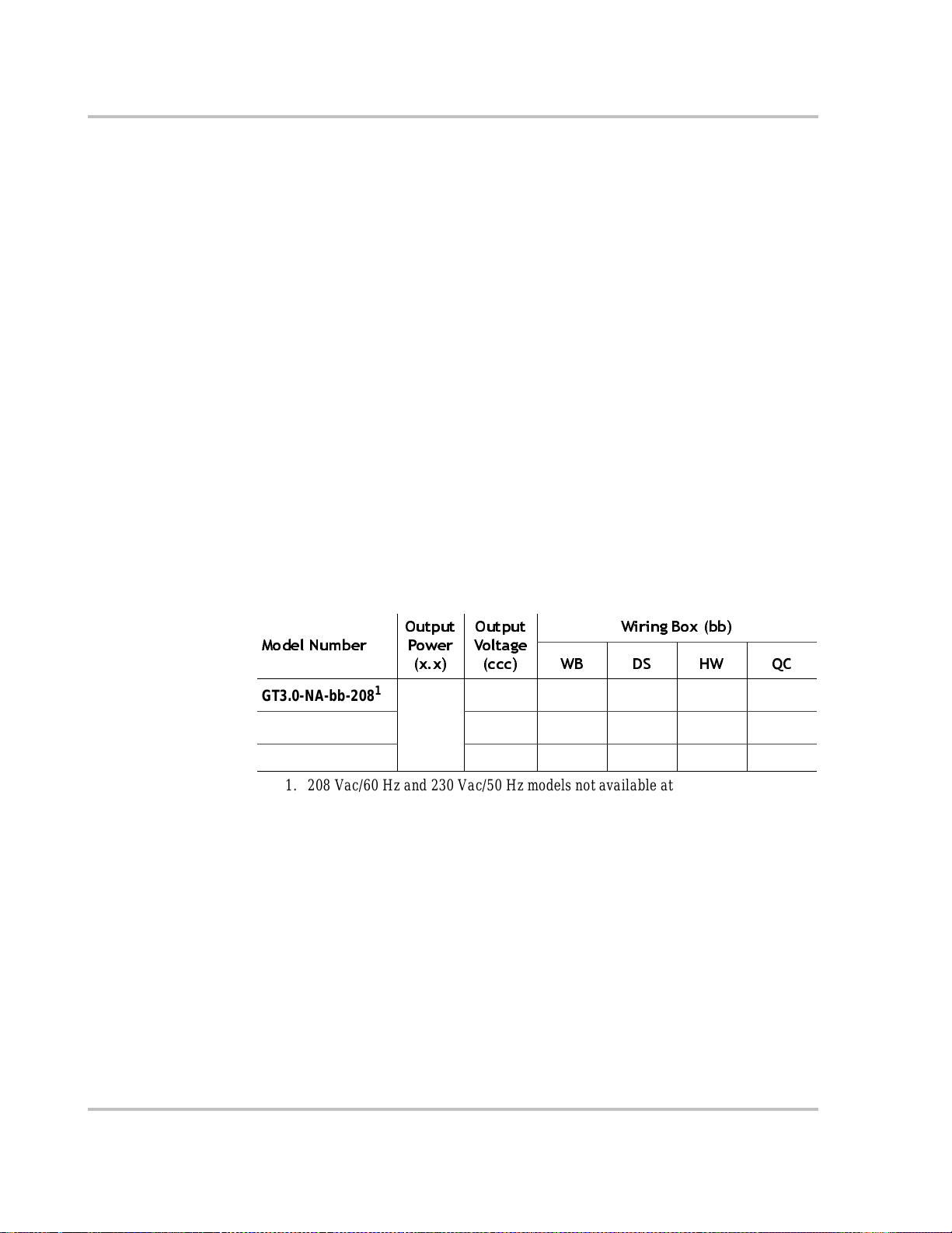
PV Grounding
In North America, PV arrays are require d to be connected to earth ground; in
Europe they are not. PV Ground Fault Protection (PVGFP) is required in North
America for ro of-mounted PV arrays.
The GT Inverter is designed to ha ve all PV positive, negative, and ground
conductors connected inside its wiring box. The PV equipment ground should be
connected to the GT Inverter ground bar. This ground bar must also be connected
to the main utility breaker panel gro und bar and to the house grounding rod
according to NEC requirements (see Figure 2-2).
The size for the conductor is usually based on the size of the largest conductor in
the DC system.
Long Distance Grounding
If the PV array is more than 30 m (100 feet) from the inverter, then there must also
be a direct connection from the array frame t o an earth ground ne xt to the array. A
connection between this ground and the building ground connection via a buried
wire between the two points is also necessary (see Figure 2-3).
Lightning Protection
Reduce the risk of lightning damage by using a single-point grounding system. In
this system, all ground lines terminat e at the same point. This point normally is the
main utility ground insta lled by the utility company to provide a ground for the
house wiring (see Fi gure 2-4). This ground usually consists of a copper rod driv en
1.5 to 2.5 meters (6 to 8 feet) in to the eart h.
2–8 975-0131-01-01

Planning the Installation
G
PV Stri ng #1
PV String #2
G
PV Array
G
GND bar
Xantr ex GT Inver ter
Wiri ng B o x
AC/DC Disconnect
Switch
Main Ut ili ty
Service Pan el
L1
NEUTRAL
GROUND
G
L2
Neutral
-to-
Ground
Bond
Primary Earth
Ground
Figure 2-2
Basic Grounding Overview
975-0131-01-01 2–9

Installation
Array
Earth
Ground
PV Array
G
PV String #2
G
Distance >30 m (100 ft)
PV String #1
When the distance between the PV Array and the GT
Inverter is gr eat er than 3 0 m (100 ft), the array sho uld have
its own earth ground, whi ch should be connected to the
Primary Earth Ground by a buried wire.
Check your local codes for grounding requirements.
Main Utility
Service Panel
L1
GROUND
L2
NEUTRAL
G
Neutral
-to-
Ground
Bond
G
Xantrex GT Inverter
Wiri ng B ox
GND bar
G
AC/DC Disconnect
Switch
Primary
Earth
Ground
(buried wire)
Figure 2-3
Long Distance Grounding Overview
2–10 975-0131-01-01
Planning the Installation
PV Array
PV String #1
G
PV Stri ng #2
G
Main Utility
Servic e Panel
L1
NEUTRAL
GROUND
G
L2
Neutral
-to-
Ground
Bond
G
Xantr ex GT I nver te r
Wiri ng B ox
GND b ar
G
AC/DC Disconnect
Switch
Primary
Earth
Ground
Figure 2-4
Grounding With Extra Lightning Protection Overview
Routing the Wires
Typical
configurations
975-0131-01-01 2–11
Determine all wire routes to and from the GT Inverter. Typical routing
configurations include:
• AC wiring from the GT Inverter to the main utility service panel
• DC input wiring from the PV array to the GT Inverter
• DC ground from the PV array to the Primary Earth Ground.
All wiring and installation methods should conform to applicable electrical and
building codes.
For installations in the United States, the National Electrical Code (NEC) and
local codes apply. For installations in Canada, the Canadian Electrical Code
(CEC) and local codes apply.
For all installations, local utilities may have additional requirements.

Installation
Conduit
holes/knockouts
Pre-plan the wire and conduit runs. Knockouts for 1.9 cm (3/4 inch) or 2.5 cm
(1 inch) conduit holes are located on the bottom and back of the wiring box.
Threaded 3/4” conduit holes are located on each side of the wirin g box
(Figure 2-5).
For maximum safety, run AC, DC, and communication wires in separate conduits.
Front of Wiring Box
Left side
1.9 cm (3/4”) Threaded
Conduit Holes
1.9 cm (3/4”) or 2.5 cm (1”) Knockouts,
also on back of Wiring Box
Right side
Figure 2-5
WARNING: Shock hazard
Check for existing electrical or plumbing prior to drilling holes in the walls.
Planning AC Wire Routing
AC connections include all the wires and connectors be tween the GT Inverter AC
terminals and the main utility service panel. Pre-plan the se routes carefully before
installing the components.
Planning DC Wire Routing
DC connections include all the wires and connectors between your PV array and
the DC terminals of the GT Inverter. Pre-plan these routes carefully before
installing the components.
Back of W i ring Box
Knockout Locations on Bottom of Wiring Box
AC/DC Disconnect Switch
2–12 975-0131-01-01

Prep aring for the Installatio n
Ensure your local utility is consulted for any requirements for connecting to or
returning power to the grid. Obtain all permits necessary to complete the
installati on. Con sult your local/national electrical code for more information.
This section includes the following topics:
•“Wiring” on page 2–13
•“Circuit Breakers and Disconnect Switch” on page 2–13
•“Other Mat erial s Need ed ” on page 2–14
•“Equipment Needed” on page 2–14.
Preparing for the Installation
Important:
DC wiring/cabling and wires/cables.
In this manual “wiring” and “wires” are used in reference to both AC and
Wiring
Wire size and length will be determined by the location of each component and
their relative distance to each other. Wire sizes may also be aff ected by whether or
not conduit is used.
Recommended wire
stripping length
Acceptable wire
sizes
Strip all wires 9 mm (3/8 inch).
The AC and DC terminal blocks in the GT Inverter accept wire sizes from
#14 AWG to #6 AWG.
Wiring should be sized such that the maximum voltage drop at full power from
the PV array to the inverter is 2% or less.
Important:
significant power losses and reduction in system efficiency.
Wiring should not be undersized. Undersizing of wiring can result in
Circuit Breakers and Disconnect Switch
The following circuit br eakers, disconnect switch and fuse are requir ed for
installing this equipment.
AC Circuit Breaker Requirements
In North America, the main utility service panel must dedicate a double pole
breaker (240 volts AC) to operate each GT Inverter ins t all ed . The GT Inverter
requires a 20-Amp breaker.
975-0131-01-01 2–13

Installation
AC/DC Disconnect Switch
The wiring b ox incl udes a PV/Util ity disconnec t s witch t hat swi tches both AC and
DC at the same time. If the inverter is to be installed without the integral Xantrex
Wiring Box with Discon nect (Xantrex Part # 100-0243-01-01), separate approved
AC and DC disconnects may be required by local authorities having jurisdiction.
WARNING: Shock hazard
The 600 volt DC/AC disconnect in the wiring box meets NEC Article 690. It is a
non-serviceable component and shall remain in place. Removal can expose energized
conductors.
Ground Fault Fuse
There is a 600 volt 1-Amp ground fault protection fuse (Litte lfuse KLKD 1 or
equivalent) in the GT Inverter.
WARNING: Shock hazard
Do not attempt to ser vice the ground fault fuse yourself. This should only be done by
qualified service personnel.
Other Materials Needed
• Mounting support material, such as plywood or poles
• Conduit for wire runs and appropriate fittings/bushings
• Wood screws and anchors for screws, depen ding on mounting surface.
Equipment Needed
• Wire cutters/wire crimpers/wire strippers
• Assorted screw d rive rs , dri ll, etc.
• Level
• Digital Voltmeter
• Frequency counter (optional, for troubleshooting).
2–14 975-0131-01-01

Mounting the Inverter
Overview
WARNING: Fire, Shock and Energy Hazards
Before installing the GT Inverter, read all instructions and c autionary markings locat ed in
this manual, on the PV array, and on the main service panel.
Mounting the Inverter
General installa tion
steps
There are four main steps in the installation of the GT Inverter:
1. Mounting the GT Inverter and installing accessories (this chapter)
2. Making the DC connections from the PV array to the GT Inverter
(“Connecting the DC Wiring ” on page 3–4)
3. Making the AC connections from the GT Inverter to the main utility service
panel (“Connecting the AC Wiring” on page 3–7)
4. Grounding the PV array (see your PV equipment documentation).
Figure 2-6 summarizes these four steps.
PV Panels
Primary Earth/
Ground
4
Utility
Meter
2
600 Vdc
Open
Circuit
Maximum
Utility Grid
3
Grid Tie Inv erter
Main Utility
1
Xantrex GT Inverter
Figure 2-6
Installation Overview
Service Panel
975-0131-01-01 2–15

Installation
In this chapter only the first step, mounting the inverter and installing accessorie s,
is described.
Mounting steps Instructions for mounting the GT Inverter are described in the foll owing sections:
•“Preparing to Mount the Unit” on page 2–16
•“Installing the Mounting Bracket” on page 2–17
•“Mounting the Inverter on the Bracket” on page 2–22
•“Installing Accessories” on page 2–23.
Multiple inverter
instructions
Mounting instr uctions for multiple inverters connected in parallel are desc ribed in
“Mounting Multiple Inverter s in Parallel” on page 2–23.
Special wiring instr uctions for multiple inverters connec ted in parallel are
described in “Connecting Inverters in Parallel” on page 3–10.
Preparing to Mount the Unit
Dimensions and Knockout Locations
The dimensions of the inverter an d the mounting bracket and some of the
knockout locations on the wiring box are shown in Figure 2-7.
Four 2 cm or 2.5 cm (3/4 inch or 1 inch) knockouts are provided on the back and
bottom of the unit to accommodate wiring:
• two on the bottom of the wiring box, on either side of the AC/DC Disconnect
Switch
• two on the back of the wiring box.
Knockout Preparation
Four 2 cm (3/4 inch) conduit holes on the sides of the wiring box are filled with
plastic plugs, which can be removed to insert conduit nipples as required for
inverters mounte d in parallel. One or two of these side conduit holes may be used
to accommodate communications wiring for multiple inverters mounted in
parallel.
Remove your choice of knockouts from the wiring box to facilitate conduit
installati on for wire runs. This is much easier to do prior to mounting the inverter.
Important:
knockouts. Be sure to install bushings or conduits in the knockout holes to protect the
wires from damage.
If installed outdoors, conduit must be seal ed where it enters the wiring box.
Ensure there are no metal shav ings left in the inve r ter after removing the
2–16 975-0131-01-01

2 cm (3/4") conduit
holes with threaded
caps, on both sides
Side view Front view
14.6 cm
5.7"
55.0 cm
21.6"
69.6 cm
27.4"
72.5 cm
28.5"
40.3 cm
Mounting the Inverter
15.9"
Heat Sink
Cover
Front Panel
Wiring Box
Dual 2 cm or 2.5 cm
(3/4" or 1") knockout s,
back and bottom
5.8 cm
2.278"
Figure 2-7
Dimensions of GT Inverter and Knockout Locations
Installing the Mounting Bracket
The mounting bracke t for the GT Inverter allows the unit to be easily m ounted a nd
dismounted for servi cing. It ha s two hooks that match correspo nding hooks on the
back side of the inverter and wiring box. The inverter can be separated from the
wiring box and removed from the bracket, leaving the wiring box in place.
Flange and
Mounting Slots
975-0131-01-01 2–17

Installation
Rectangular slot s × 25 :
8 mm × 30 mm
(5/16" × 1-3/1 6")
Mounting bracket Back side of the inverter
25.3 cm (10")
Mounting flanges
Figure 2-8
Mounting Bracket and GT Inverter
Clearance Requirements
For optimal and safe operation, ensure there is adequate clearance around the
inverter. The minimum clearance recommendations in Table 2-2 assume a vertical
mounting. If clearances are reduced below these minimums, rated power may not
be achieved.
Table 2-2
Location Minimum Clearance
Above 30 cm (12 inches)
Below:
• Inverter
• Bracket
In front Sufficient room to allow for easy access to read the display and to
On sides 15 cm (6 inches) to prevent thermal derating. When mounting units
58.7 cm (23.1")
Mounting slots for securing the inverter
Inverter Clearance Requirements
Outdoors:
• 100 cm (39 inches)
• 110cm (43inches)
Indoors: the same clearances are
recommended but not required.
prevent accidental contact with hot surface.
side by side, 30 cm (12 inches) of clearance between the two units is
recommended.
Mounting flanges
The inverter extends below the
bracket by approximately 10 cm
(4 inches)
2–18 975-0131-01-01

Surfaces for Mounting
Mounting the Inverter
WARNING: Shock hazard
Before drilling holes to mount the GT Inverter, ensure there are no electrical wires or
plumbing in this area.
WARNING: Personal inju ry
The GT Inverter weighs approximately 20 kg (45 lbs). Always use proper lifting
techniques during installation to prevent personal inju ry.
WARNING: Explosion hazard
Do not store combustible or flammable materials anywhere near the inverter.
The GT Inverter weighs approximate ly 20 kg (45 lbs). The supporting surface
must be strong enough to handle 75 kg (160 lb). If the supporting surfa ce is not
strong enough to handle that weigh t, the n supporting material such as a sheet of
plywood can be used to enhance the strength of the mounting sur face.
The GT Inverter can be mounted to a vertical surface such as wallboard, wood
siding, concrete wall or pole assembly.
Mounting on poles
or rails
Mounting to
wallboard with
support
Mounting to siding
using wall studs
Mounting to
concrete surface
• See “Mounting on Poles o r Rails” on pa ge 2–20. Ensure the bottom of the unit
is a minimum of 100 cm (39 inches) from the ground if mounted outdoors.
• Installation onto wa llboard requires either the use of a supporti ng material
such as plywood or securing the mounting screws to supporting wall studs.
Use at least two screws and anchors to secure the unit to the supporting
material.
• If mounting to exterior siding using a wall stud for support, the plywood
backing will not be needed. Use at least two lag screws to secure the unit to
the supporting materi al. Ensure the screws enter the stud at least 4 cm
(1.5 inches) to adequately support the weight of the unit. See “Mounting on
Wallboard, Siding or Concrete” on page 2–21.
• If mounting the unit on a concrete surf ace using anchors with no supporting
material, use f our sc rews an d ancho rs, i nstead of two, to adequate ly secure the
unit and distribute the weight.
Important:
or other high-risk areas.
Important:
the GT Inverter.
Local codes may impose additional mounting r equirements in earthquake
Other than the mounting b r ac ket, no mounti ng hardware is supplied with
975-0131-01-01 2–19

Installation
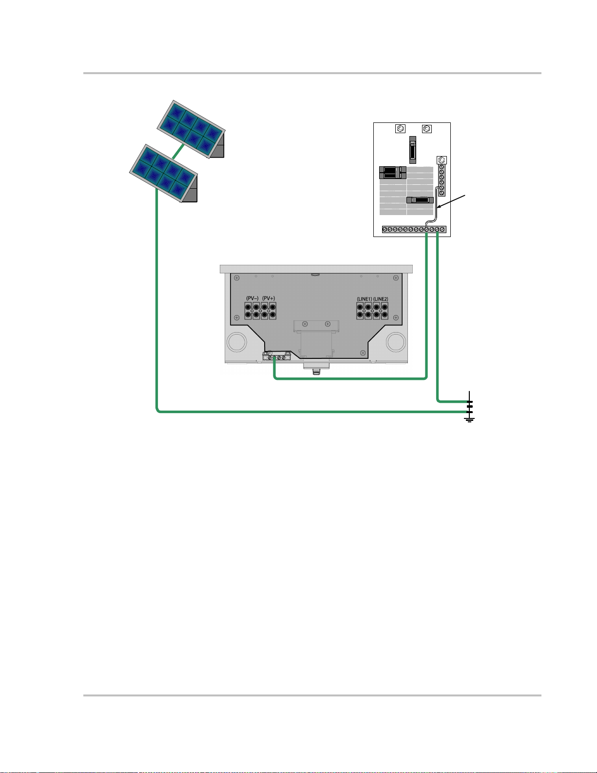
Mounting on Poles or Rails
To mou nt the uni t us ing po les :
1. Ensure that poles or rails are securely assembled in place. If using horizontal
rails, three rails are required: two for the mounting bracket and a third for
securing the bottom edge of the inverter wiring box (see Figure 2-9).
2. Connect the mounting bracket vertically to the poles or rails (Figure 2-9):
• Be sure to use at least two bolts to secure the mounting bracket to the
• Position the lower edge of the bracke t a minimum of 110 cm (43 inches)
3. If using a single vertical pole, ensure that the inverter is secure and unable to
rotate around the pole.
support.
above the floor or ground.
Mounting Bracket
Ground /
Floor
Figure 2-9
At least 2 bolt s to
secure b racket t o
poles/rails.
110 cm
(43”)
For sec u ring
the bottom of
the wiring box
Examples of Mounting on a Pole or Rails
48 cm
(18.9”)
15 cm
(5.9”)
100 cm
(39”)
Ground /
Floor
2–20 975-0131-01-01

Mounting on Wallboard, Siding or Concrete
To mount the GT Inverter to wallboard, siding, or concrete:
1. Locate the area where the GT Inverter is to be installed.
2. Install backing support material if required. See Figure 2-10.
Mounting the Inverter
Figure 2-10
At least 2 screws
with washers to
secure bracket
to plywood
110 cm (43")
Ground / Floor Ground / Floor
Single GT Inverter Dual GT Inverters
30 cm (12")
110 cm (43")
Installing the Mounting Bracket using Plywood Support
3. Using a level, place the mounting bracket against the wall surface at least
110 cm (43 inches) from the ground. See Table 2-2 on page 2–18 to ensure
minimum clearance requirements are met.
4. Mark the location for mounting screws if using a wall stud for support. At
least four mounting screws and anchors are needed for concrete installations
or wallboard installa tions where no wall studs are available for support.
For multiple inverters mounted in parallel, the brackets should be mounted
30 cm (1 2 inch es) ap art . Inv er te rs mo unted le ss tha n 30 cm (12 inches ) ap ar t
may not achieve full rated power.
5. Remove the bracket and drill the holes using an appropriately sized drill bit.
Drill appropriately sized holes for screws or anchors.
6. Secure the bracket to the supporting surface using at least two screws and
washers.
975-0131-01-01 2–21
Installation
Mounting the Inverter on the Bracket
Mounting a Single Inverter
To mou nt the in v erte r on the mo un ti ng bra c ket:
1. Place the GT Inverter’s mounting hooks, located on the back of the enclosure,
over the bracket and ensure the inverter is seated properly, as shown in
Figure 2-11.
2. After the unit is correctly seated on the bracket hooks, locate the mounting
slots in the flange below the wiring box and mark the location on the wall for
securing screws.
3. Remove the inverter and drill pilot holes in the wallboard or siding for the
securing screws.
4. Reinstall the GT Inverter on the bracket and se cure the bottom of the uni t with
appropriate screws or anchors, and tighten.
Slide the mounting hooks on the inverter
over the hooks on the mounting bracket.
flange with
mounting slots
Figure 2-11
2–22 975-0131-01-01
Proper Placement of the Inverter on the Mounting Bracket
Ensure the inverter is seated
properly on the mounting bracket

Mounting Multiple Inverters in Parallel
As shown in Figur e 2-10, inverters can be mounted side by side on wallboard or a
plywood support. A minimum of 30 cm (12 in ches) of cleara nce betwee n the uni ts
is recommended.
Conduit nipples should be insta lled on one side of the first inverter before
mounting on the bracket. Ensure that the sealing ring is located on the conduit
nipple between inverters, i.e., on the outside of the wiring box. The lock nut is
attached after the nipple is inserted into the conduit hole of the second inver ter
Instal li n g Acc e ssories
The optional fan assembly and heat sink cover (see Figure 1-5 on page 1–7)
should be installed toge ther. Neithe r accessory should be installed without the
other.
Installing the Fan Assembly
WARNING: Shock hazard
If the inverter is already installed and oper ational, turn OFF the breaker switc hes in the
main utilit y se rvice panel and the AC/DC Disconnect switch on the inverter wiring box
before performing thi s pro ce dure.
Installing Accessories
WARNING: Shock hazard
Hazardous voltag es may be present when cover is removed. After disconnecting all
sources of ener gy, wait 5 minutes before removing cov er.
WARNING: Burn hazard
Ensure that the in verter and heat sink are not too hot to touch before attempting this
procedure.
Important:
The fan assembly (see Figure 1-5 on page 1–7) is optional for the GT Inverter.
Installing the fan ass embly involves two main steps:
1. Attaching the fan assembly to the inver ter.
2. Connecting the fan wires.
The fan assembly should only be installed by qualified personnel.
975-0131-01-01 2–23

Installation
To attach the fan assembly to the inverter:
1. Using a Phillips screwdriver, remove the four panhead screws and washers
from the front panel of the inverter (two screws on each side), immediately
below the heat sink (see Figure 2-12).
2. Place the fan bracket with screw holes overlapping the screw holes on the
inverter. The fans should be facing up, on the upper side of the fan bracket.
3. Replace the four panhead screws and washers removed in step 1.
Figure 2-12
Attaching the fan assembly
2–24 975-0131-01-01

Installing Accessories
To connect the fan wires:
1. Remove the wiring box cover b y removing t he two sc rews on the under side of
the wiring box. Removing the wiring box cover will expose the screws that
secure the front panel cover.
2. Remove the front pa nel cove r by r emoving the two screws on the unde rside of
the front panel.
3. Plug the wire leads from the fan assembly into the pin connectors on the DC
circuit board. The pins are located to the left of the LCD below the ground
fault protection f use.
4. Replace the front panel cover using the screws removed in step 2, with the
wire leads passing through the notch at the top of the cover, ensuring that the
wires are not pinched.
5. Replace the wiring box cover using the screws rem oved in step 1.
Fan connectors
Figure 2-13
Location of Fan Connector
975-0131-01-01 2–25

Installation
Installing the Heat Sink Cover
You may find it easier to install the heat sink cover before mounting the inverter.
If the inverter is already installed and in operation, it is best to perform the
following procedure s after dark or on an overcast day when the unit is cool.
WARNING: Burn hazard
Ensure that the inverter and cover are not too hot to hold firmly before installing or
removing the heat sink cover.
To install the heat sink cover on the inverter:
1. Hold the heat sink cover vertically in front of you with the curved edge
upward and the flanges bent away from you.
2. Insert the heat sink cover le ft side flange into the groove on the le ft side of the
inverter heat sink. It should snap into place.
3. Push the cover so that it curves outward (awa y from the inve rter) and insert
the right side fl ange into the groove on the right side of the inverter heat sink.
It should snap into place.
To remove the
Important:
on the right side .
1. Press the righ t si de of the hea t si nk cover inwar d (i. e., towa rd the l eft side) and
simultaneously lif t it upwards to pull it out of the groove on the right side of
the inverter.
2. Pull the left side of the cover out of the inverter left side groove.
heat sink cover from the inverte r:
You may start with the left or right side of the co ver. This example starts
2–26 975-0131-01-01

3
W iring the Inverter
Chapter 3, “Wiring the Inverter”, provides procedures for making DC
and AC wiring connections, and grounding the GT Inverter and the
PV array. Instructions for wiring inverters in parallel are also
provided.
The topics in this chapter are organized as follows:
•“Accessing the Wiring Terminals” on page 3–2
•“Connect ing the DC Wiring” on page 3–4
•“Connect ing the AC Wiring” on page 3–7
•“Connecting Inverters in Parallel” on page 3–10.

Wiring the Inverter
Accessing the Wiring Terminals
You must remove the GT I nverter wiring box cover to access the terminal bloc ks,
ground bar and communications por ts (for inverters in parallel).
To remove the wiring box cover:
1. Using a Phillips screwdr iver , remove th e two screws on the bott om side of the
wiring box and set in a safe place (see Figure 3-1 for location of screws).
2. Lift the cover off the wiring box.
When replacing the wiring box cover, be careful not to pinch any wires in the
wiring box.
Wiring box
cover screws
Knockouts
Figure 3-1
AC and DC connections are made at the wiring terminals shown in Fi gure 3-2.
Insulating barrie r The clear plastic insulating barri er inside the wiring box is a permanent
component. It is intended to separate the high-voltage AC and DC wiring from
any communicatio ns cabling and to pr event wiring from coming into contact with
the wiring box cover.
When wiring the unit, it is necessary to pull the cover back to access the wiring
terminals. Aft er com pleting the wir ing, re place t he insul at ing barr ier to its or ig inal
position.
Communications
wiring
For multiple i nve rt ers in pa rall el , com mu n icat io n s wiri ng i s conn ected b etw een
RJ45 connectors on each invert er (see Figure 3-9).
Removing the Wiring Box Cover
3–2 975-0131-01-01

Accessing the Wiring Terminals
Figure 3-2
DC Terminals
for connecti ng
PV arrays
AC/DC
Disconnect
Switch
AC and DC Terminal Block Location in the Wiring Box
AC Terminals for
connecting to mai n
utility service panel
975-0131-01-01 3–3

Wiring the Inverter
Connecting the DC Wiring
WARNING: Shock hazard
Whenever a PV array is exposed to sunlight, a shock hazard exists at the output wires or
exposed termin als. Ensure that the AC/DC Disconnect Switch is set to OFF before
commencing any wiring. See Figure 3-3.
WARNING: Shock hazard
The 600 volt AC/DC disconnect in the wiring box meets NEC Article 690. It is a
non-serviceable component and shall remain in place. Removal can expose energized
conductors.
Figure 3-3
The following proc edure is illus trated i n Figure 3-4. If there will be more than one
PV string, label the positive and negative wire pairs appropriately ( f or example:
PV 1, PV 2).
3–4 975-0131-01-01
AC/DC Disconn ect Switch Positions

Connecting the DC Wiring
To wire the PV array to GT Invert er:
1. Install DC conduit from the PV string(s) to the GT Inverter wiring box,
through one of the knockout holes.
2. Remove the wiring box cover (see page 3–2).
3. Route the wires from th e PV string(s) through the conduit and into the wiring
box.
4. Connect the DC Ground from each PV string to the GROUND bar in the
wiring box.
5. Connect the POSITIVE (+) wire from the #1 PV string to the
PV1 (+) terminal. Double check that the wire is in the proper location and
tighten the screw.
6. Connect the NEGATIVE (–) wire fro m the #1 PV strin g to the
PV1 (–)terminal. Double check that the wire is in the proper location and
tighten the screw.
7. Repeat for the #2 PV string, if there is one. Double check that the wires are in
the proper locations and tighten the screws:
a) Connect the POSITIVE (+) wire from the #2 PV string to the
PV2 (+) terminal.
b) Connect the NEGATIVE (–) wire from the #2 PV strin g to the
PV2 (–)terminal.
8. Ensure all connection s are corre ctly wired and properly torqued according to
values shown in Table 3-1.
Table 3-1
14 to 10 2.5 to 6.0 35 4.0
Torque Values for Wires*
Wire Size T orque
AWG mm
8 10.0 40 4.5
6 25.0 45 5.1
2
in-lb Nm
*Use copper conductors only.
975-0131-01-01 3–5

Wiring the Inverter
PV String #2
G
–
+
G
PV Array
G
–
+
PV String #1
Xantrex GT I nverter
Wiring Box
GND bar
AC/DC Disconnect
Switch
Figure 3-4
Important:
box may be required. This fusing is to be provided by the installer .
3–6 975-0131-01-01
DC Connections for Grounded PV Array
Depending upon installation and local codes, fusing and/or a combiner

Connecting the AC Wiring
WARNING: Shock hazard
AC utility wiring to the GT Inverter unit is performed directly at the main break er panel.
This should be done only by a qualified installer or electrician.
WARNING: Shock hazard
Before wiring the G T Inverte r, e nsure the ma in breaker in t he primary utility b r eaker box
is switc hed OFF. Switch this break er ON onl y af ter all wir ing i s comple ted a s ins tructe d in
the procedures.
Connecting the AC Wiring
Important:
inverter to be connected to a dedicated circu it and no other outlets or devices ma y be
connected to this circuit. The NEC also i mposes limitations on the size of the inverter and
the manner in which it is connected t o the utility grid. The ci rcuit breakers t hat are used in
the mai n p an el that feed the inverter circ u i t must be for b ack-fed oper ation and labeled as
such.
The GT Inverter can be connected to a single bi-directional meter, or to dual
meters, where one meter indicate s power used and the second meter indicates
power sold (power supplied back to the util ity). Consult with the local utility to
determine the proper co mponents to install, and obtain any permits required prior
to installation.
The following procedure is illustrated in Figure 3-5.
Important:
In the United States, the National Electrical Code (NEC) requires the
Neutral conductor wiring is not r equired in this in stallation.
975-0131-01-01 3–7

Wiring the Inverter
To wire the main utility service panel to the GT Inverter:
1. Install conduit f rom the main utility service panel to the wiring box of the GT
Inverter. Run the two HOT wires (L1 and L2) and ground wire from the
service panel through the conduit and into the inverter wiring box.
2. Install or use an existin g double-pole 20-Amp circuit breaker (or two
single-pole br eakers, ga nged) in the main utili ty se rvice pane l, and ensu re that
the breakers are set to OFF.
3. Connect the ground wire (green or bare copper) from the ground bar in the
main utility service panel to the GND bar in the wiring box.
4. Connect the L1 HOT wire (black) from the double-pole breaker installed in
the main utility servic e panel, to the L1 GRID terminal in the wiring box.
5. Connect the L2 HOT wire (red) from the double-pole breaker installed in the
main utility service panel, to the L2 GRID terminal in the wiring box.
6. Ensure all connection s are corre ctly wired and properly torqued according to
values shown in Table 3-1 on page 3–5.
3–8 975-0131-01-01

GND bar
Xantre x GT Inver ter
Wiri ng B o x
AC/DC Disconnect Switch
L1
L2
Connecting the AC Wiring
Utility Grid
L1 L2 Neutral
Utility
Meter
L1 L2 Neutral
Main Utility
Service Panel
L1
GROUND
L2
NEUTRAL
Neutral
Ground
Bond
-to-
Figure 3-5
G
Primary Earth
Ground
AC Connections from GT Inverter to Utility Service Panel
975-0131-01-01 3–9

Wiring the Inverter
Connec ting Inverters in Parallel
GT Inverters can be connected in a parallel configuration for larger PV array
systems. In thi s confi g urat i on, separate solar array s are requ i red fo r eac h GT
Inverter unit. The output of each GT Inverter feeds a separate dual-pole 20-Amp
circuit breaker (L1 and L2) in the main utility service panel.
DC and AC Wiring for Inverters in Parallel
The following procedures a re illustrated in Figure 3-6. The illustration and
instructions assume only two inverters, but in fact more than two inverters can be
used in a parallel configuration.
If there will be more than one PV string, label the positive and negativ e wire pairs
appropriately (for example: PV 1, PV 2).
Connecting DC
wiring
Connecting AC
wiring
To wire the PV array to GT Inverters in parallel:
1. Install the DC conduit from the PV strings to the GT Inverter wiring boxes,
through appropriate knockout holes. Metal conduit is highly recommended.
2. Remove the wiring box cover (see page 3–2).
3. Route the wires from th e PV string(s) through the conduit and into the wiring
box.
4. Connect the DC Ground from each PV array to the GND bar in the wiring
box.
5. Follow the instructi ons on page 3–4 for connecting POSITIVE (+) and
NEGATIVE (–) wires from each PV arra y to each GT Inverter.
6. Ensure all connection s are corre ctly wired and properly torqued according to
values shown in Table 3-1 on page 3–5.
To wire the main utility service panel to the GT Inverters in parallel:
1. Run conduit from the main uti lity service panel to the wiri ng boxes of the GT
Inverters.
2. Follow the instruc tions on page 3–7 for connecting L1 a nd L2 HOT wires and
ground wire from the main utility service panel to each GT Inverter.
3. Ensure all connection s are corre ctly wired and properly torqued according to
values shown in Table 3-1 on page 3–5.
3–10 975-0131-01-01

Connecting Inverters in Parallel
Figure 3-6
975-0131-01-01 3–11
Parallel GT Inverter DC and AC Wiring

Wiring the Inverter
Communications Wiring for Inverters in Parallel
Communications wiring betwe en GT Inverters mounted in parallel allows
informatio n ab out eac h inve rt er and its ass oci at ed PV arra y to be comm u ni cat ed
between all of the inverter s in the system. Information about the entire system can
be displayed on any inverter LCD in the system.
For example, in a two-inverter system, if inverter #1 is producing 1500 W and
inverter #2 is producing 2000 W, both inverters display a total system power of
3500 W. The cumulative energy pro duced by both inverters that day is also
displayed.
You can still view infor mation f or an individua l i nverter i n a syst em. Se e “To view
unit-specific screens in a multiple unit system:” on page 5–5.
Without commun icat ions w iring each inverter in a system will on ly dis pl ay
information perti nent to the unit and its associated PV array.
Xanbus Network Technology
GT Inverters use Xanbus technology to communicate with other inverters in
parallel. Communications wiring between inverters is laid out in a “daisy chain”
pattern, each device on the network linked together with separate lengths of cable,
as shown in Figure 3-7.
For more information on instal ling a Xanbus network, see the Xanbus System
Installation Guide , available at www.xantrex.com.
Xanbus-enabled
Device 1
Terminator
Figure 3-7
Daisy Chain Layout
Xanbus-enabled
Device 2
Xanbus-enabled
Device 3
Terminator
CAUT ION: Equip men t dama ge
Connect only Xanbus-enabled devices.
Although th e cabling and connec tors used in this network system are the same as ethernet
connectors, this network is not an ethernet system. Equipment damage may resul t from
attempting to connect Xanbus to different systems.
3–12 975-0131-01-01

Communications Wiring for Inverters in Parallel
T erminators Male network terminators (Figure 3-8) are r equired at both ends of the network to
ensure the communication signa l quality on the network.
GT Inverter Xanbus
Ports
Figure 3-8
Male Network Terminator
Two RJ45 ports are provided in the GT Inverter, accessib le fro m the wiri ng box.
See Figure 3-9 for the location of these ports.
RJ11 ports
(not used)
Figure 3-9
RJ45
Xanbus ports
RS-232 port (used to connect a PC to use the GUI.
See “Custom Screens” on page 5–9)
Male network terminator
Xanbus RJ45 Ports in the GT Inverter Wiring Box
975-0131-01-01 3–13

Wiring the Inverter
Cabling Requirements
CAUTION: Equipment damage
Do not use crossover cable in a Xanbus system.
The network uses Category 5 (CAT 5) cable, a standard cable availabl e from any
computer supply store. The cable consist s of e ight condu ctors in four twi ste d pairs
with an RJ45 modula r connector wired to the T568A standard. Table 3-2 contains
the arrangements of wire colors to pin numbers for the T568A standard.
Table 3-2
Pin Number Conductor Name CAT 5 Cable Insulation Color
1 NET_S White/Green
2NET_S Green
3 NET_C White/Orange
4 CAN_L Blue
5 CAN_H White/Blue
6 NET_C Orange
7 NET_S White/Brown
8 NET_C Brown
RJ45 Connector Requirements
The network cable uses modular RJ45 connectors, as shown in Figure 3-10. The
connector is suitable for cost-sensitive applications and is easily installed. The
RJ45 connector should be a modular plug, 8-position, 8-contact for round,
stranded, unshielded cable.
T568A Standard Wiring
Figure 3-10
3–14 975-0131-01-01
RJ45 Connector

Purchasing Network Components
Consult with your syste m desi gner to de ter mine what networ k component s wil l be
needed for your specific installation. Table 3-3 provides a partial list of network
components and part numbers. Pre-made cables are available in standard len gths
from 3 feet to 75 feet .
Call your dealer or visit www.xantrex.com to purchase network components.
Communications Wiring for Inverters in Parallel
Table 3-3
Network Component Part Number
Network termination — Male (2 per pack) 809-0901
Network cable 3 ft. (0.9 m) 809-0935
Network cable 5 feet (1.5 m) 809-0936
Network cable 7 feet (2.0 m) 809-0937
Network cable 10 feet (3.0 m) 809-0938
Network cable 14 feet (4.3 m) 809-0939
Network cable 25 feet (7.6 m) 809-0940
Network cable 50 feet (15.2 m) 809-0941
Network cable 75 feet (22.9 m) 809-0942
Network Components and Part Numbers
Guidelines for Routing the Network Cables
WARNING: Shock hazard
:
Do not route the network cabl es in the same conduit or panel as the AC and DC power
cabling.
To ensure maximum performance of your network, follow these guidelines when
routing the network cables. Route the cables before installing Xanbus-enabled
devices.
• Route the cables away from sharp edges that might damage the insulation.
Avoid sharp bends in the cable—no less than a 10-cm (4-inch) radius.
• Allow for som e slac k in the cab l e ten sion .
• Keep the alignment of wire pairs inside the sheath as straight as possible.
• Allow separation between da ta and power cable s (data cables should only
cross a power cable at right angles).
• Do not staple the cable with metal cable staples. Use the appropriate hardware
fasteners to avoid damage to the cable.
CAUTION: Unpredictable device behavior
Do not connect one end of the network to the other to make a ring.
975-0131-01-01 3–15

Wiring the Inverter
Connect the Communications Cable between Inverters in Parallel
WARNING: Shock hazard
If the inverter is already installed and oper ational, turn OFF the breaker switc hes in the
main utilit y se rvice panel and the AC/DC Disconnect switch on the inverter wiring box
before performing thi s pro ce dure.
WARNING: Shock hazard
Hazardous voltag es may be present when cover is removed. After disconnecting all
sources of ener gy, wait 5 minutes before removing cov er.
The following procedure is illustrated in Figure 3-11 on page 3–17. The
illustration and procedure assume only two inverters connected in parallel.
However, there can be more than two inverters wired in this configur ation.
To provide communication between inverters mounted in parallel:
1. Remove the wiring box cover from each unit.
2. On each unit, remove the plug from a 1.9 cm (3/4”) side conduit hole and
install appropri ate conduit between the two units.
3. Connect the communication cable to any RJ45 port in Inverter #1.
4. Pass the cable through the conduit be tween Inverter #1 and Inverter #2.
Inside each unit’s wiring box, ensure the communication cable runs
horizontally alo ng the flat-bottomed channel formed when the insula tion
barrier is in place. The cable should r un on top of the insulation barrier and
out the side conduit hole, avoiding any contact with the AC and DC wiring.
5. Connect the communication cable to any RJ45 port in Inverter #2.
6. For more than two inverters in parallel, continue connecting cable as
described above.
7. Insert male network termina tors into the empty RJ45 ports in the inverters at
the beginning and end of the network. There should be no empty RJ45 ports.
3–16 975-0131-01-01

Communications Wiring for Inverters in Parallel
PV Array #2
G
–
+
PV Array #1
G
–
+
Communications cable
in separate condu it fr om AC and DC wiring.
Figure 3-11
Xantrex GT Inverter #1
Wiring Box
Male Te rmin at or
GND bar
AC/DC Disconnect
Switch
GND
G
L2
L1
Communications Wiring for GT Inve rt er s in Parallel
Xant r ex GT I nve rt e r #2
Wiring Box
Male Terminator
bar
AC/DC Disconnect
Switch
L2
G
L1
To Utility Service Panel. See
Figure 3-6 on page 3–11 for
details of wiring connections.
975-0131-01-01 3–17

3–18

4
Starting the Inverter
Chapter 4, “Starting the Inverter”, contains information on starting up
the Xantrex Grid Tie Solar Inverter and performing a Functional Test.
The topics in this chapter are organized as follows:
•“Startup Procedure” on page 4–2
•“Replacing the Wiring Box Cover” on page 4–3.

Starting the Inverter
Startup Proce du re
Starting up the GT Inverter requires severa l steps. You will need to:
1. Ensure the AC/DC Disconnect switch loc ated on the bottom of the G T
Inverter unit is in the OFF position (see Figure 4-1).
2. Check the PV array DC voltage (see procedure below).
3. Check the AC utility voltage (see procedure below).
4. Replace the cover on the wiring box (see “Replacing the Wiring Box Cover”
on page 4–3).
5. Start up the GT Inverter by switching the AC/DC Disconnect switch ON.
WARNING: Shock hazard
Hazardous voltages are present from two sources. Use extreme caution during star tup
procedure. Before applying power to the GT Inverter, ensure all AC and DC wiring is
correct.
Checkin g the PV Array DC Voltage
To check the PV array DC voltage:
1. Uncover the PV arrays and expose them to full sunlight. The sunlight must be
intense enough to produce the required output voltage.
2. Measure the PV arr ay open circuit DC voltage across the DC positive (+) and
negative ( –) terminals. This voltage must be greater than 150 volts DC to
energize the electronics.
Checking the AC Utility Voltage
To check the AC utility voltage:
1. Switch on the main and inverter breakers in the main electrical service panel.
2. Using an AC voltmeter , measure the AC open circuit utility volta ge betwe en
L1 and L2. Ensure this voltage is at approximately the nominal value. The
inverter operate s with a line-to-line voltage (L1 to L2) range around the
nominal value.
See “Output” on page A–2 for the operating utility voltage range for the GT
Inverter.
4–2 975-0131-01-01

Replacing the Wiring Box Cover
After performing the volta ge checks, replace all covers that were removed during
installation and startup.
WARNING: Shock hazard
Before reattaching cove r s, turn OFF the breaker switches in the main utility service panel
and the AC/DC Disconnec t s witch on the GT Inverter.
If the front panel cove r wa s remo v ed fro m the GT Inverter, then it mus t be
replaced before the wiring box c over is r eplaced.
To replace the front panel cover:
1. Place the cover in position on the front panel, being careful not to pinch any
wires. The fan wires should pass through the notch in the upper edge of the
front panel cover.
2. Ensure that the two screw holes in the bottom of the front pa nel cover are
aligned with the corresponding holes in the bottom of the inverter (not the
wiring box).
Replacing the Wiring Box Cover
3. Replace the two screws removed when the cover was removed (see
“Installing the Fan Assembly” on page 2–23), and tighten securely.
To replace the wiring box cover:
1. Place the cover in position on the wiring box, being careful not to pinch any
wires in the wiring box.
2. Ensure that the two screw holes in the bottom of the wiring box cover are
aligned with the corresponding holes in the bottom of the wiring box.
3. Replace the two screws removed when the cover was removed (see
“Accessing the W iring Terminals” on page 3–2), and tighten securely.
975-0131-01-01 4–3

Starting the Inverter
Starting up the GT Inverter
To start up the inverter:
1. Switch the AC/DC Disconnect switch to the ON position (see Figure 4-1).
2. Check the GT Inverter LCD. The startup screens (see Table 5-1 on page 5–3)
shou l d a p pear f o r five second s e a ch, and the n the “Reconnecting in sss
seconds” special screen (see Table 5-10 on page 5–8) will appear until the
five-minute, five-second (default value) protec tion timer countdown is
completed.
AC/DC Disconnect Switch
Figure 4-1
AC/DC Disconn ect Switch Positions
4–4 975-0131-01-01

5
Monitoring the Inverter
Chapter 5, “Monitoring the Inverter”, contains information for
understanding the LCD screens and the LED indicators.
The topics in this chapter are organized as follows:
•“Monitoring the Front Panel Display” on page 5–2
•“Front Panel Display Screens and What They Mean” on page 5–3
•“Status Indicator Lights” on page 5–9.

Monitoring the Inverter
Monitoring the Front Panel Display
During startup During startup, the inverter’s front panel LCD (see Figure 5-1) shows the first
three screens described in Table 5-1, “Startup Screens on GT Inverter Front Panel
Display” on page 5–3.
During waiting
period
When the five-minute, five-second (305 seconds) protection timer begins, the
inverter displays “Reconnecting in sss seconds” (see Table 5-10, “Special
Message Screens” on page 5–8).
During operation When the protection timer stops, the GT Inverter begins selling power, indicated
by the power output reading in the displa y (see Tabl e 5-2, “Normal Operation
Default Scr een” on page 5–4).
When the inverter is
offline or ther e is
fault condition
When the GT Inverter is offline (e.g., at night) or a fault cond ition has been
detected, the LCD shows a message screen to indicate that state. The specific fault
condition will be identified. See Table 5-5, “Offline Mode Default Display” on
page 5–5 and Table 5-8, “Fault Message Screens” on page 5–7.
Important:
The values in the front panel LCD are not user adjustable.
Front panel LCD
Tap Xantrex logo for
backlight/ status screens.
V iewing more
information
Figure 5-1
Additional screens of infor mation about the performanc e of the G T Inverter c an be
displayed by tapping the Xantrex logo on the inverte r front panel. This causes the
Front Panel LCD Location
LCD to cycle thr ou gh a se ries of info rma tio n screen s in No rma l Op era tio n,
Offline or Fault modes. The se are described in detail in the following section,
“Front Panel Display Screens and What They Mean”.
5–2 975-0131-01-01

Front Pane l Display Screens and What They Mean
Fro n t Panel Di splay Screens and What They Mean
The front panel display shows dif ferent message screens during diff erent modes of
operation (Sta rtup, Normal, Of fline , and Fault). All singl e units displ ay a basic set
of message screens; multiple unit systems display additional screens in Normal
Operation and Offline modes.
In addition there are Special message screens that may appear in any operational
mode. All of these message screens are descr ibed in more detail in the following
tables.
Startup Mode
During startup, the GT Inverter displays three message screens on its f ront panel
LCD. These screens appear in the following order (Ta ble5-1).
Table 5-1
GT3.0-NA-240
Flash = 01.01
..ROM = 01.01
Vh=262 Vl=212
Fh=60.5 Fl=59.3
* all numbers in this and following tables are examples only.
Startup Screens on GT Inverter Front Panel Display
Display*
Xantrex
Duration Description
5 sec. Startup message 1: Inverter name and model
number
5 sec Startup message 2: Model and revision
numbers for Fl ash and ROM memory on the GT
Inverter. The ROM revision number applies to
the protectio n pr oce ssor.
5 sec Startup message 3: Anti-islanding Utility Grid
trip points.
Vh: high voltage threshold
Vl: low voltage threshold
Fh: high frequ enc y threshold
Fl: low frequency thres hold
The five-minute, fiv e second prot ection tim er begins it s countdown dur ing startup
and the “Reconnecting in sss seconds” s creen appear s until the timer count down i s
complete.
Normal Operation Mode
The LCD on the GT Inverter is refreshed every two seconds, so all readings are
current to within two sec onds. There is a default displa y availabl e at all times, and
a series of additional scre ens that can be displayed by tapping the Xantrex logo
near the LCD to change the display.
Normal Operation
default display
975-0131-01-01 5–3
After the protection tim er has completed its countdown and during normal
operation, the GT Inverter displays the normal oper ation mess age screen shown in
Table 5-2.

Monitoring the Inverter
More screens for all
systems
Table 5-2
System 2000W
Today 9.875kWh
Normal Operation Default Screen
Display Description
Power being produced by the system now.
Cumulative energy produced by the system today.
If there is sufficient energy from the PV array, this screen is displayed
continuously while the system is operating normally. In a multiple unit system
with communications cables properly connected, the power and cumulative
energy values displayed are for the entire system.
During low light conditions when the GT Inverter cannot produce any power, the
Normal Operation default screen flashes alternately (every two seconds) with the
Insufficient Solar Energy screen (see Table 5-10, “Special Mes sa ge Screens” on
page 5–8).
Besides the default normal opera tion display, more system information message s
can be viewed .
To view more Normal Operation information:
• T ap the Xantrex logo near the LCD to advance the display to the next scree n.
Normal operati on screens shown i n Table 5-3 are displayed in the or der given,
as you tap successively on the unit. They are common to all GT Inverter
systems, no matter how many units are installed.
If you continue to tap the unit, then the LCD continues to cycle through all of the
available normal operation screens. Each screen is displayed for a maximum of
30 seconds. If you do not tap again during that time period, then the LCD
backlight turns off and the display reverts to the default system message screen.
Table 5-3
Tap Display* Description
1st tim e
2nd time
3rd time
4th time
5th time
Normal Operation Screens for All GT Inverter Units
System 2000W
Today 2.500kWh
System Lifetime
305kWh
Time Online
Today hh:mm:ss
Array Readings
350.5V 8.4A
Grid Readings
242.6V 60.0Hz
LCD backlight turns on for better readability
and default Normal Operati on screen is
displayed.
Lifetime energy produced by the GT Inverter
system.
Length of time in verter has be en onli ne today, in
hours (hh), minutes (mm) and seconds (ss).
Immediate DC voltage and curre nt readings
from the PV array.
Immediate AC voltage and frequency readings
from th e G r id
5–4 975-0131-01-01

Front Pane l Display Screens and What They Mean
* In a multiple unit system with communications cables properly installed, the
system values displayed are for the entire system. For example, in a
two-inverter system, if inverter #1 is producing 1500 W and inverter #2 is
producing 2000 W, both inverters display a total system power of 3500 W.
Time online and array readings are for the local inverter and PV array
associat ed with that inverte r.
Additional
messages for
multiple unit
systems only
In addition, to the normal system message screens, additional screens spe cific to
each GT Inverter unit can be displayed when the unit is networked to other GT
Inverters. These scree ns are only available on multiple unit systems.
To view unit-specific screens in a multiple unit system:
1. T ap the Xantrex logo near the LCD to advance the display to the next scree n.
Continue tapping until the final system message screen (“Grid Readings”, in
Table 5-3 above) is displayed.
2. T ap again. Normal operation screens shown in Table 5-4 are displayed in the
order given, as you tap successiv ely on the unit.
If you continue to tap the unit, then the LCD will cy cle throug h all of the avail able
normal operation scree ns. Each message is displayed for up to 30 seconds. If you
do not tap again within that time per iod, then the LCD backlight turns off and the
display reverts to the default normal operation screen (Table 5-2).
Table 5-4
Additional Normal Operation Screens for Each GT Inverter Unit in a
Multiple Unit System
Tap Display Description
6th time
7th time
Unit 1500W
Today 1.250kWh
Unit Lifetime
150kWh
Power being produced by thi s uni t now.
Cumulative energy produced by this uni t today .
Lifetime energy produced by this GT Inverter unit
Offline Mode
Offline default
display
Offline message s
for all systems
975-0131-01-01 5–5
At night and when no power is bei ng produce d by t he PV array ( of fline mode), the
GT Inverter displays the screen shown in Ta ble 5-5.
Table 5-5
Offline Mode Default Display
Display Description
Inverter
Offline
Displayed at al l times w h il e th e sy s t em is offlin e.
Additional message screens can be viewed when the system is offline by tapping
the Xantrex logo near the LCD. Each additiona l tap displays the next screen, in
the order shown in Table 5-6.

Monitoring the Inverter
These message screens are common to all GT Inverter systems, no matter how
many units are installed. If you continue to tap the unit, then the LCD will
continue to cycle through all of the available offline mode screens.
Additional Offline
messages for
multiple unit
systems
Table 5-6
Tap Display*
1st tim e
2nd time
3rd time
4th time
* In a multiple unit system with communications cables properly installed, the
Offline Mode Screens for All GT Inverter Units
Description
Inverter
Offline
System 0W
Today 2.50kWh
System Lifetime
305kWh
Time Online
hh:mm:ss
system val ues d isp lay ed a re fo r t he e ntir e sys tem. Tim e o nlin e is for the loca l
inverter.
LCD back light turns on for better readability
and default Offline Mode screen is displayed.
Power being produced by the system now.
Cumulative energy produced by the system
today.
Lifetime energy produced by the system.
Total time that the system was online today, in
hours (hh), minutes (mm) and seconds (ss).
Multiple unit systems in offline mode display all of the message scre ens shown in
T able 5-6, plus the additional screens shown in Table 5-7. These additional
screens are displayed f ollowing the “Time Online” screen.
These screens are only displayed on multiple unit GT Inverter systems with
communications cabling properly installed. If you continue to tap the unit, then
the LCD continues to cycle through all of the avai lable offline mode screens.
Table 5-7
Additional Offline Mode Screens for Each GT Inverter Unit in a
Multiple Unit System
Tap Display Description
5th time
6th time
Unit 0W
Today 1.25kWh
Unit Lifetime
150kWh
Power being produced by thi s uni t now.
Cumulative energy produced by this unit today.
Lifetime energy produced by this unit.
Fault Mode
When a fault state is detected, the appropriate fault message appears on the front
panel display at the next scree n ref resh (i.e., within 2 seconds). The GT Inverter
fault message screens are shown in Table 5-8.
5–6 975-0131-01-01

Front Pane l Display Screens and What They Mean
Fault Mode causes These message screens only appear when there is a fault, and then flash
alternately with the Inverter Offline default screen (Table5-5) until the fault is
corrected.
Table 5-8
DC Voltage Fault
AC Voltage Fault
Frequency Fault
Over Temp Fault
81.4C 178.5F
Ground Fault
Reset System
Fault Message Screens
Display Description
145.5V
280V
0.0Hz
When the actual DC voltage is over or under the allowable
range, 165 to 600 Vdc. Self-clearing, no action required.
The PV array should be configured such that DC voltage
does not fall below 195 Vdc or rise above 600 Vdc.*
When the actual AC voltage is over or under the allowable
range , as sp ecified in “Output” on page A –2.
This is a utili ty f ault; it will clear itself when th e AC voltage
comes within the specified ran ge.†
When the actual Frequency is over or under the allowable
range, as specified in “Output” on page A–2. This is a utility
fault; it will clear itself when the frequency c omes within t he
specified range.
When the unit’s internal temperat u r e is g re at er th a n 8 0 ° C
(176° F), the unit will shut down automatically and only
restart when the temperature has dropped to less than 70° C
(158° F).
When a grounding fault is detected. The ground fault fuse
will be blown. The system must be shut down completely,
the fault corrected, the fuse replaced (see “Replacing the
Ground Fault Protection Fuse” on page 6–4) and then the
system restarted. Troubleshooting a grounding fault should
be performed by qualifie d pers onnel.
†
Impedance Fault
Detected
Unit Shutdown
via Remote
Protection uP
Not Responding
* It is normal to recei ve this fault durin g low light condi tions at dawn or dusk. At
such tim es, th e array d oes no t ha ve suff ici ent ener gy to po we r the in ver ter, s o
the PV voltage drops below 165 volts occasionally.
† Grid fault. When this fault is cleared the protection timer will begin its
countdown and you will see the “Reconnecting in s ss seconds” and “Inverter
Offline” special screens (see Table 5-10) flashing alternately until the
countdown is complete.
975-0131-01-01 5–7
Applicable only in German installations.
Appears if the GT Inverter unit has been shut down via a
computer connected to the RS-232 port.
The protection processor is not responding.
†

Monitoring the Inverter
Additional Fault
messages for all
systems
Additional message screens can be viewed in fault mode by tapping the Xantrex
logo near the LCD. Each additional tap displays the next screen in the order
shown in Table 5-9.
Table 5-9
Tap Display*
1st time Curre n t f a u lt me ssage
2nd time
3rd time
4th time
5th time
6th time
* In a multiple unit system with communications cables properly installed, the
Additional Fault Mode Screens
Description
LCD backlight turns on for better readability.
screen (see Table 5-8 )
System 0W
Today 2.500kWh
System Lifetime
305kWh
Time Online
Today hh:mm:ss
Array Readings
350.5V 8.4A
Grid Readings
242.6V 60.0Hz
system values displayed are for the entire system. Time online and array
readings are for the local inverter and PV array associated with that inve r ter .
Energy being produced by the system now.
Cumulative energy produced by the system
today.
Lifetime energy produced by the GT Inverter
system.
Length of time inverter was online today, in
hours (hh), minutes (mm) and seconds (ss).
Immediate DC voltage and curre nt readings of
power from the PV array.
Immediate AC voltage and frequency readings
of power from the Grid.
Special Screens
Special message screens are displaye d in specific situations that are not
considered fault situations. They can appear in any mode of operation. These
screens are described in Table 5-10.
Table 5-10
Reconnecting in
sss seconds
5–8 975-0131-01-01
Special Message Screens
Display Description
Time remaini ng in seconds (sss) before the GT Inverter
reconnects to th e G r id . Th i s is a pr o t ection ti m e r ; it ru n s for
approximately five minutes at startup and after any Grid fault.
Inverter
Offline
GT Inverter switching (or has switch ed) from Normal
Operation to Offline mode. This screen may flash alternately
with a F au l t m essage scr een.

Status Indicator Lights
Custom Screens
Table 5-10
System *3500W
Today 15.56kWh
Unit *1800W
Today 7.82kWh
Insufficient
Solar Energy
Special Message Screens
Display Description
The “*” in these two screens (see Table 5-2 and Table 5-4)
indicates that the unit is derating its output power because the
invert er heat sink temperature is abov e 75 ° C (167° F).
The asterisk only appears when the power is actua lly being
limited by the inverter.
Indicates the GT Inverter is not producing power due to
insufficient solar energy during low light conditions in early
morning or late aftern oon or when the PV array is in shade.
This scr een flashes alternately with the Normal Op eration
default screen.
Two custom screens are available. The inverter does not display them unless they
are configured using a computer connected to the RS-232 port inside the wiring
box. If programmed, the custom scree ns display as the fourth and fifth screens
during the startup seque nce. They can also be viewed by tapping the unit during
normal operation and fault mode.
The first custom screen is inte nde d for the home owner to display information
such as the name or location of the PV array associated with the inverter.
The second custom scre en is intended for instal lers, who can configure the screen
to display, for example, contact info rm at io n for serv i ce .
A PC graphical user interface that can be used for configuring custom screens is
available for download at www.xantrex.com.
Status Indicator Lights
The GT Inverter is equipped with two sta tus indic ator lights ( LEDs) loc ated be low
the front panel LCD (Figure 5-2). These LEDs indicate the inver ter’s current
status (Table 5-11) and assist in troubleshooting the perf or mance of the unit.
Only one indicator light will be lit at any time.
Table 5-11
LED on Means
GREEN GT Inverter is on (DC voltage and AC voltage are qualif ied and the
975-0131-01-01 5–9
Status Indicator LEDs
protection timer has fi nished) and delivering energy to the grid. No
action required. Turns off when a fault state is detected.
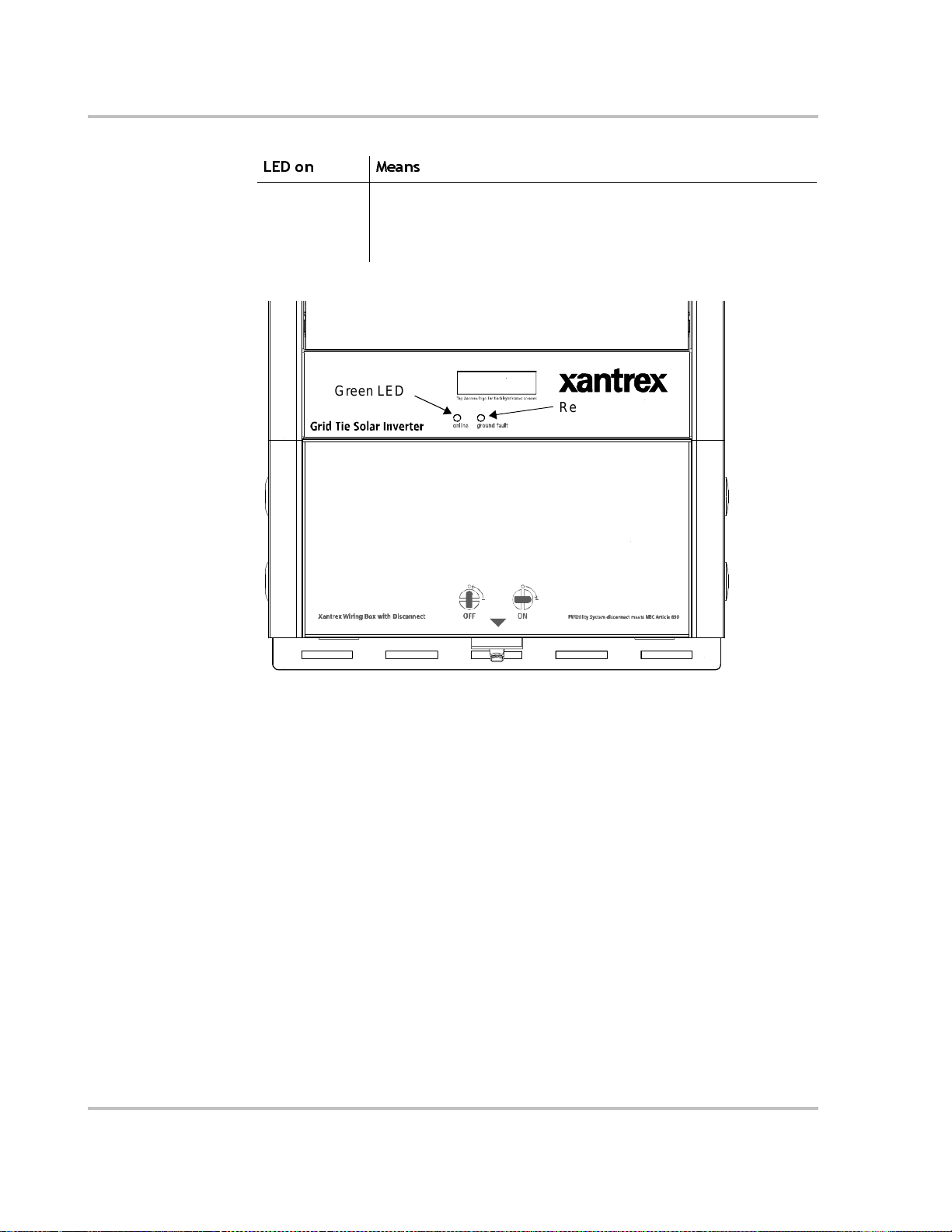
Monitoring the Inverter
Table 5-11
LED on Means
RED Ground fault condition detected.
Status Indicator LEDs
Check for any fault messages on the display (see Ta ble 5-8), and refer
also to Table 6-1, “Trou bleshooting the GT Inverter” on page 6–8 to
resolve the f ault condition.
Green LED
Red LED
Figure 5-2
5–10 975-0131-01-01
Location of Status Indicator Lights

Maintenance and
6
Troubleshooting
Chapter 6, “Maintenance and T roubleshooting”, contains information
about how to provide general maintenance for the Xantrex Grid Tie
Solar Inverter. It also provides information about troubleshooting the
unit.
The topics in this chapter are organized as follows:
•“Factors Affecting GT Inverter Performance” on page 6–2
•“Performing General Maintenance” on page 6–3
•“Replacing Parts” on page 6–3
•“Identifying Error/Fault Conditions and Solutions” on page 6–8.

Maintenance and Troubleshooting
Factors Affecting GT Inverter Performance
This section describes several factors that will affect the amount of power that a
properly install ed and operating GT Inverter can produce.
PV Array Factors
PV array ratings PV arrays are rated at ideal f actor y conditions, such as specified illum ina tion
(1000 W/m2), spectrum of the light and specified temperature (25°C / 77°F),
which seldom reflect real-world installations. This is called the STC (Standard
Test Condition) rating and is the figure that appears on the PV module nameplate
label.
Expected
performance
Temperature and
reduced output
Angle of the sun The angle of the sun in relation to the PV array surface—the arra y
Partial shade Shading of only a single module of the array will reduce the output of the entir e
Because of several unavoidable environmental factors, you can expect your
PVarray to produce around 60% to 70% of its peak STC-rated output for a
properly designed and ins talled PV system on a typical day.
PV array temperature affects the output of the entire system. As the temperature
on the array surface heats up, its energy output goes down. Roof-mounted arrays
also collect the heat generate d by the roof surface (or tr apped under the array ) and
will produce less output than pole-mounted arrays, which allow greater air
circulation behind the panels.
Important:
circuits from overheating and possible damage in high heat conditions. For maximum
output in hot climates, mount the GT Inverter in a shaded location with goo d air flow.
orientation—can dr amatically affec t the PV array outpu t. The array energy output
will vary depending on the time of day and time of year as the sun’s angle in
relation to the array cha nges. Sunlight output decreases as the sun approaches the
horizons (such as in winter in North America) due to the greater atmospheric air
mass it must penetrate, reducing both the light intensity that strike s the array’s
surface and spec trum of the li ght. In general , you can e xpect only four to s ix hour s
of direct sunlight per day.
system. Suc h sh ading can b e cau sed by som et h ing as sim ple as the sh ad ow of a
utility wire or tree bran ch on part of the array’s surface. This condition, in eff ect,
acts like a weak battery in a flashlight, reducing the total output, even thoug h the
other batteries are good. However, the output loss is not proportionate to shading.
The GT Inverter will reduce its energy output to protect its electronic
The GT Inverter is designed to maximize its energy production in all of the above
situations using its MPPT algorithm.
6–2 975-0131-01-01

Other Factors
Other factors that contribute to system losses are:
• Dust or dirt on the array
• Fog or smog
• Mismatched PV array modules, with slight inconsistencies in performance
from one module to another.
• Inverter efficiency
• Wir e l osse s
• Utility grid voltage.
For additional i nformation and technical note s concerning PV array perform ance,
please visit our Web site at www.xantrex.com.
Performing General Maintenance
Follow these simple routi nes to ensure many years of service and optimal
performance of your solar ener gy system.
1. Keep the heatsink clear of dust and debris.
Performing General Maintenance
WARNING: Shock and fire hazard
Do not use a pressure washer to clean the GT Inverter, or use other cleaning methods that
could allow water to enter the unit.
2. Clean the PV array, during the cool part of the day, whenever it is visibly
3. Periodically inspe ct the system to make sure that all wiring and supports are
4. On a sunny day near noon on March 21 and September 21 of each year,
Replacing Parts
WARNING: Shock hazard
There are no us er-replaceable parts on the GT Inverter. Do not attempt to service the unit
yourself.
See the “W arranty and Return Information” on page WA–1 for information on
how to get service for your GT Inverter.
dirty.
securely in pla ce.
review the output of the system and compare with previous year’s reading.
Maintain a log of system performance readings so that you can recognize
when system performance becomes inconsistent.
975-0131-01-01 6–3

Maintenance and Troubleshooting
Replacing the Ground Fault Protection Fuse
WARNING: Shock and fire hazard
Fuses should only be replaced by qualified service personnel. For continued protection
against risk of fire, replace only with same type and ratings of fuse.
WARNING: Shock hazard
After disconnect ing both AC and DC power from the GT Inverter, wait five minutes
before attempting any maintenance or cleaning or working on any circuits connected to
the inverter. Internal capacitors remain char ged for five minutes after disconnecting all
sources of power.
WARNING: Shock hazard
Danger o u s voltages can exist inside the inverter. If ther e is leakage c urrent from t he
POSITIVE PV lead to ground at the array , touching the NEGATIVE PV lead could cause
a life-thre atening shock even wit h the disconnect switch turned off . Ungrounded negative
DC current on the PV NEGATIVE (–) wire present s an extreme s h o ck hazard.
When the fuse has blown due to a fault, incorrect handling can be life-threatenin g. Use an
insulated fuse puller.
If possible, cover PV arrays wit h an opa que material during this procedure.
The ground fault protection f use will blow when severe leakage occurs between
the PV array and earth ground, or when the system has been inst alled with faulty
wiring. Before replacing the fuse, it is important to have qualified service
personnel determine the caus e of the ground fault.
To replace a ground fault protection fuse:
1. Remove the wiring box and front panel covers (described on page 2–23 and
page 3–2). The ground fault protection fuse is located on the left side of the
LCD panel, behind the front panel cover (Figure 6-1).
2. Using an insulated fuse pulle r, remove the blown fuse and replace it with a
new AC/DC midget cartridge, rated 600 Vdc, 1A (Lit telfuse KLKD 1 or
equivalent).
3. Replace the front panel and wiring box covers (described on page 2–23 and
page 4–3).
6–4 975-0131-01-01

Replacing Parts
Figure 6-1
Ground Fault
Protection Fuse
Location of Fuse, Front Panel Cover Removed
LCD
Replacing the Inverter
You can swap out the inverter and re pla ce it with another GT Inverter, leaving the
existing wiring box in place. This means that you do not have to disturb wiring
connections in the wiring box. However, you do have to disconnect wiring
between the inverter and the wiring box.
WARNING: Shock hazard
Separating the inverter from the wiring box breaks the ground path between PV
NEGATIVE (–) and earth ground. When the wires between the inverter and wiring box
are disconnec ted a nd expos ed, b oth PV l eads ar e float ing at the array open ci rcuit v olt age.
If there is leaka ge curre nt from t he POSITIVE PV l ead to g round a t the array, touching the
NEGATIVE PV lead could cause a life-threa tening shock even wit h the dis connec t switch
turned off . Ungrounded negative DC current on th e PV NEGATIVE (–) wire presents an
extreme shock hazard.
Use insulated tools only when disconnect ing wires between the invert er and wiring box.
Cap all disconnected wires with wire nuts.
If possible, cover PV arrays wit h an opa que material during this procedure.
975-0131-01-01 6–5

Maintenance and Troubleshooting
Recommended tools:
• Insulated screwdriver
• Wire nut for PV NEGATIVE (–) wire
• 7 mm socket and small ratchet, or 7 mm open wrench.
WARNING: Shock hazard
i
The inverter shoul d only be removed from the wiring box when a replace ment inverter is
immediately available. When replacing an inv erter, ensure t h e A C/DC Disconnect switch
is locked (or otherwis e secured) in the OFF positio n. Do not leave the top of the wiring
box exposed for extended periods of time.
WARNING: Shock hazard
Before replacing the inverter, turn OFF the brea ker switches in the main utility se r vice
panel and the AC/DC Disconnect switch on the GT Inverter.
To remove the inverter from the wiring box:
1. Turn OFF the breake r switches in the main utility service panel and the
AC/DC Disconnect switch on the G T Inverte r. If possible, cover the PV arrays
with an opaque material.
2. Remove the covers from the wiring box and inverter front (described on
page 2–23 and page 3–2).
3. Using an insulated screwdriver, disconnect the PV NEGATIVE (–) wire from
the te rmi na l bl oc k insi d e th e inve rt er. Cap the wir e im m edi at e ly wi th a wi r e nu t.
4. Disconnect the remaini ng AC, DC and communications wires between the
inverter and the wiring box, inside the inverter. Cap all disconnected AC and
DC wires with wire nuts.
5. Inside the inverter, remove the four nuts attaching the wiring box to the
inverter.
6. Lift the inverter off the mounting bracket, leaving the wiri ng box in place.
6–6 975-0131-01-01

Front view Back view
Inverter
Lower flange
behind wiring box
Wiring box
Replacing Parts
Figure 6-2
Inverter and Wiring Box Sections
To replace the inverter on the wiring box:
1. If it has not already been removed, remove the front panel cover on the
inverter now. The wiring box cover should have be en remov ed in the pr evious
procedure.
2. Mount the invert er on the upper mounting bracket above the wiring box, with
the lower flange behind the wiring box.
3. Replace the nuts that connect the inverter and the wiring box. Secure all nuts
tightly.
4. Remove the wire nut from the PV NEGATIVE (–) wire and reconnect i t to the
terminal block inside the inverter.
5. Uncap the remaining DC and AC wires and reconnect them to the terminal
block inside the inverte r.
6. Replace the front panel and wiring box covers (described on page 2–23 and
page 4–3).
7. Turn ON the brea ker swi tches in t he main utilit y se rvice panel and the AC/ DC
Disconnect switch on the GT Inverter.
975-0131-01-01 6–7
Maintenance and Troubleshooting
Identifying Error/ Fault Conditi on s an d Solution s
Most error or fault conditions will be identified by fault message screens on the
GT Inverter front panel LCD. These are described in the “Fault Mode” section on
page 5–6 of this manual. Most of these fault conditions are self-correcting and
require no user action to remedy.
See “Front Panel Display Screens and What They Mean” on page 5–3 for more
information.
Table 6-1 is intended to assist in determining fault conditions that may require
user action to remedy.
Table 6-1
Problem Cause Remedy
• The inverter LED
indicator li ghts do not
illuminate, and the
inverter does not
operat e in suf fic i e nt
sunlight
• The display reads
“Inverter Off line”
• The Vdc reading is 0.
Only the inverter RED
LED is illuminated.
Tr oubleshooting the GT Inverter
AC/DC Disconnect Switch
is off, or utilty service
panel AC or DC breakers
are switched off.
No AC grid or DC array
voltage is present.
Ground fault condition
detected.
Turn on AC/DC Disc onnect Switch and breaker s in the
sequence described in “St artup Procedure” on page 4–2.
Check source of the AC voltage. Ensure that the inverter
AC/DC Disconnect Swit ch is set ON.
Check AC connections and ensure AC voltage within the
range specified in “Output” on page A–2 is present.
Check DC connectio ns. Check the DC voltage on the
positive and ne gative input terminalsand ensure
195–550 Vdc is prese nt.
Check for incorrectly wired PV arrays or try again on a
day with brighter sunl ight intensity.
Check for any fault messages on the dis play (see
Table 5-8 on page 5–7). System should be checked by a
qualified electrician and repaired.
6–8 975-0131-01-01

A
Specifications
Appendix A, “Specifications”, contains information about the
electrical and environmental specifications of the Xantrex Grid Tie
Sola r Inverter.
The topics in this appendix are organized as follows:
•“Electrical Specifications” on page A–2
•“Environmental Specifications” on page A–5
•“Mechanical Specifica tions ” on page A–5

Specifications
Electric al Specif ications
Input
Input voltage, Maxim um Power Point range 195 to 550 Vdc
Absolute maximum array open circuit voltage 600 Vdc
Maximum input current 16.6 A DC
Maximum array short circuit curre nt 19 A DC
Recommended PV array power Up to 3300 W
Reverse polarity protection Short circuit diode
Ground fault protection GF detection, I
DIF
> 1 A
Output
GT3.0 North American GT3.0 European
Maximum output power 3000 W AC 3000 W AC
Nominal output power over rated te m p range 2500 W AC 2500 W AC
Maximum utility backfeed current 20 A 20 A
Nominal output voltage 240 V 230 V
Operating range, utility voltage (default)*
Nominal output frequency 60 Hz 50 Hz
Operating range, utility frequency (default)* 59.3 to 60.5 Hz 47.1 to 50.9 Hz
Maximum continuous output current 14.2 A 14.9 A
Output overcurrent protection 20 A RMS 20 A RMS
Total Harmonic Distortion (THD) < 5% <5%
Power factor >0.9 >0.9
Utility monitoring—islanding protection Vac, fac as per UL1741
211 to 264 Vac 202 to 253 Vac
Output characteristics Current source
Output current waveform Sine wave
* Requires Utility permission and qualified service personnel to change settin gs.
A–2 975-0131-01-01

Adjustable Disconnect Settings
The adjustable disc onnect setti ng v alues va ry depe nding on whet her the inv erter is
a 208 Vac/60 Hz, 240 Vac/60 Hz, or 230 Vac/50 Hz model. Utility permission is
required prior to changi ng the settings on the inverter.
The default values of these settings differ from the utility specifications on
page A–2. These differences take into account the accura cy ranges listed in the
table below, and are intended to ensure that utility specifications a re always met.
Default Values Adjustme nt Range
Electrical Specif ications
Setting
Accuracy208 Vac/60 Hz 240 Vac/60 Hz 230 Vac/50 Hz From... To...
AC Low Voltage 186 Vac 214 Vac 205 Vac
180 Vac 269 Vac +/– 3 Vac
AC High Voltage 225 Vac 261 Vac 250 Vac
AC Low Frequency 59.4 Hz 47.1 Hz
46.0 Hz 62.0 Hz +/ – 0.1 Hz
AC High Frequency 60.4 Hz 50.9 Hz
Reconnect Delay 305 sec. 60 sec. 600 sec. +/– 5 sec.
Output Power Versus Ambient Temperature
Once the heat sink on th e invert er reach e s a maxi m u m te mperature limi t, the GT
Inverter reduces its energy output to ensure maximum component ratings are not
exceeded.
GT3.0 GRID TIE SOLAR INVERTER
Output Power versus Ambient Temperature
3500
3000
2500
2000
1500
Power (Watts)
1000
500
0
-25-15-5 5 152535455565
Figure A-1
Output Power vs. Ambient Temperature
Ambient Temper ature (C)
Standard Unit w/ Optional Fan Kit
975-0131-01-01 A–3

Specifications
Efficiency
Maximum efficienc y 94.6%
Efficiency at 75% of nominal
94.5%
output power rating
Euro effi ci en c y 93.3%
Nighttime tare loss 1 W
TYPICAL EFFICIENCY [%]
at 195VD C, 240VA C , 25 C
100
90
80
Efficiency (%)
70
60
50
0 500 1000 1500 2000 2500 3000
Figure A-2
Output Power (W)
Typical Efficiency
A–4 975-0131-01-01

Environmental Specifications
Rated operating temperature range -25° to +45° C (-13° to +113° F)
Tolerable operatin g temperat u re
range
Storage tempera ture range -40° to +85° C (-40° to +185° F)
Power derating Derating curv e ab ove +45° C (+113° F);
Tolerable relative humidity limit Operating: 100% conde nsing
User Display
Type alphanumeric liquid crystal
Size 2 lines by 16 characters
Backlight yes
Display Accuracy
Instantaneous Power +/- (30 W + 1% of reading)
Voltage +/- (1% of rating + 1% of reading)
Current +/- (1% of rating + 1% of reading)
System Lifetime energy +/- 5%
Environmental Specifications
-25° to +65° C (-13° to +149° F)
see Figure A-1 on page A–3
Storage: <95%, non-condensi ng
Mechan ical Specificat io n s
Outdoor enclosure NEMA 3R, Rainproof
Inverter dimensions
(H × W × D)
Shipping dimensions
(H × W × D)
Inve r t e r w eight 20 .4 kg (45 lb)
Shipping weight 26.6 kg (58.7 lb)
Input and output terminals
Disconnect switc h Integrated switch, disconnects both AC and DC (meets
975-0131-01-01 A–5
72.5 × 40.3 × 14.6 cm (28. 5 × 15.9 × 5.7
86.6 × 51.8 × 26.2 cm (34 × 20.4 × 10.3 inches)
AC and DC terminals ac cept wi re sizes of 2. 5 to 25 mm
(#14 to #6 AWG)
NEC article 690), rated @ 600 Vdc
inches)
2

Specifications
Accessories
GT Fan Kit (includes fan assembly and heat sink cover)
Part number 864-0201
Fan contro l Thermal, activa tes when the internal surfa ce of the hea t sink
reaches 60° C (140° F).
Fan power consumption
(operating)
3.84 W
A–6 975-0131-01-01
 Loading...