

Owner’s Manual
SW Communications
Adapter (SWCA)

About Xantrex
Xantrex Technology Inc., is a world-leading supplier of advanced power
electronics and controls with products from 50 watt mobile units to 1 MW utilityscale systems for wind, solar, batteries, fuel cells, microturbines, and backup power
applications in both grid-connected and stand-alone systems. Xantrex products
include inverters, battery chargers, programmable power supplies, and variable
speed drives that convert, supply, control, clean, and distribute electrical power.
Trademarks
Trace and Xantrex are registered trademarks of Xantrex International.
Notice of Copyright
SW Communications Adapter (SWCA) Owner’s Manual © April 2002 Xantrex
Technology Inc. All rights reserved.
Disclaimer
While every precaution has been taken to ensure the accuracy of the contents
of this guide, Xantrex International assumes no responsibility for errors or
omissions. Note as well that specifications and product functionality may change
without notice.
Since the use of this manual and the conditions or methods of installation,
operation, use and maintenance of the unit are beyond the control of Xantrex
Technology Inc., the company does not assume responsibility and expressly
disclaims liability for loss, damage, or expense arising out of or any way connected
with such installation, operation, use, or maintenance.
Due to continual improvement through product updates, photographs and/or
illustrations used in this manual may not
Technology Inc., reserves the right to update this product without notice or releasing
an updated manual when
fit, form or function
exactly
match your unit. Xantrex
are not affected.
Date and Revision
April 2002, Revision A
Part Number
973-0022-01-01
Contact Information
Web: www.xantrex.com
Email: dpm@xantrex.com
Phone: 360.435.8826
Fax: 360.435.2229
ii
©2002 Xantrex Technology Inc.
P/N 973-0022-01-01 Rev A 04/2002
IMPORTANT SAFETY INSTRUCTIONS
This manual contains important safety instructions that should be followed
during the installation and maintenance of this product.
To reduce the risk of electrical shock, and to ensure the safe installation and
operation of this product, the following safety symbols have been placed throughout
this manual to indicate dangerous conditions and important safety instructions.
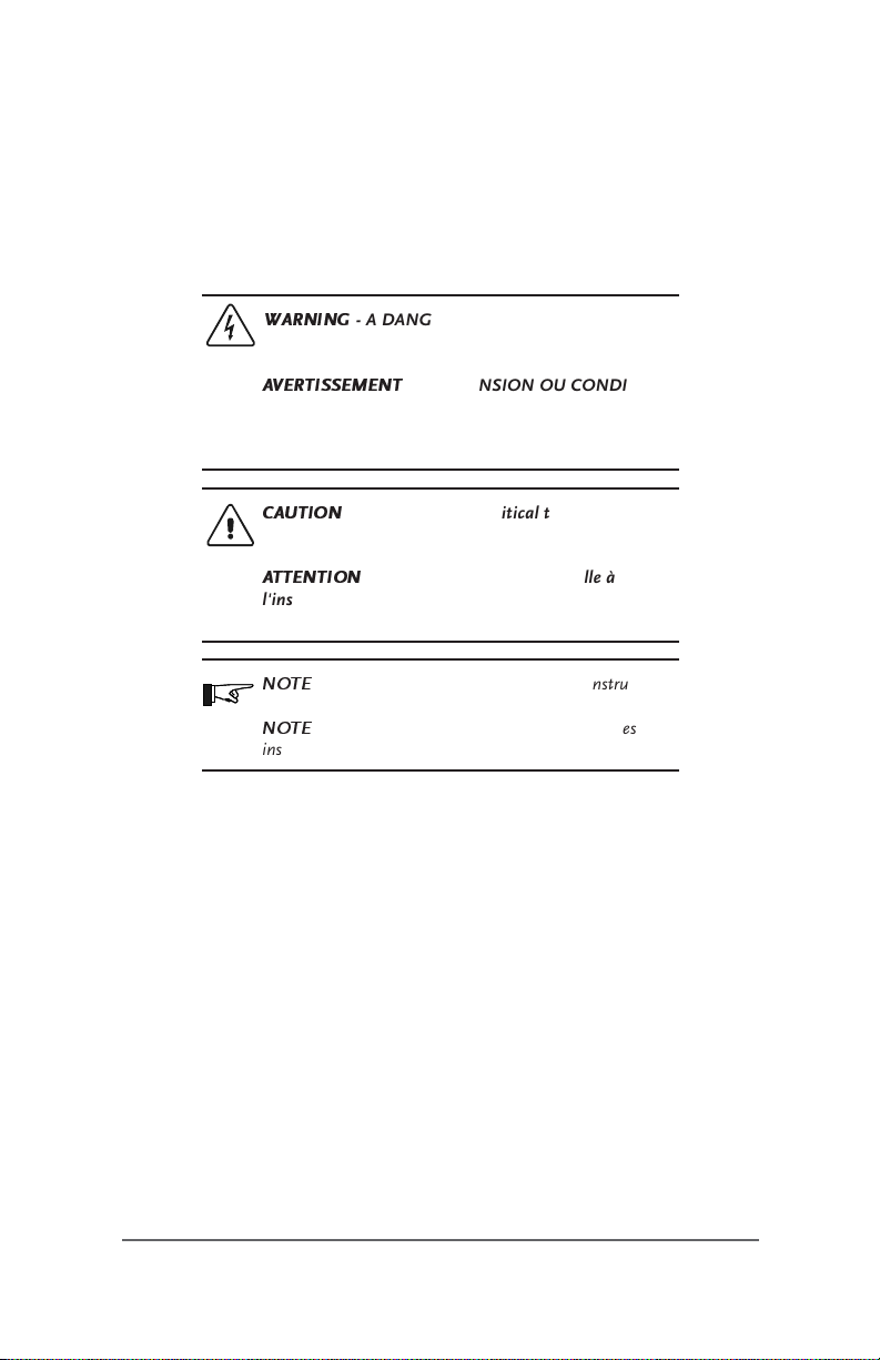
WARNING
CONDITION EXISTS IN THIS AREA. USE EXTREME
CAUTION WHEN PERFORMING THESE TASKS.
AVERTISSEMENT
DANGEREUSE EXISTE DANS CETTE ZONE. FAIRE
PREUVE D’EXTRÊME PRUDENCE LORS DE LA
RÉALISATION DE CES TÂCHES.
CAUTION
installation or operation of the unit. Follow these
instructions closely.
ATTENTION
l’installation ou l’utilisation de l’unité en toute sécurité.
Suivre ces instructions de près.
NOTE
closely.
NOTE
instructions de près.
• All electrical work must be done in accordance with local, national, and/or
international electrical codes.
• Before installing or using this device, read all instructions and cautionary
markings located in the manual, and on the inverter, the batteries, and the PV
array.
• Do not expose this unit to rain, snow or liquids of any type. This product is
designed only for indoor usage.
• This product contains no user-serviceable parts. Do not attempt to repair this
unit.
- A DANGEROUS VOLTAGE OR
- UNE TENSION OU CONDITION
- This procedure is critical to the safe
- Cette procédure est essentielle à
- This statement is important. Follow instructions
- Cette déclaration est importante. Suivre les
©2002 Xantrex Technology Inc.
P/N 973-0022-01-01 Rev A 04/2002
iii
Table of Contents
IMPORTANT SAFETY INSTRUCTIONS........................................................... iii
1.0 INTRODUCTION ............................................................... 1
2.0 INSTALLA TION.................................................................. 3
To install the SWCA ........................................................................................... 3
Connecting the SWCA to a Computer using a Modem ............................ 4
Requirements ............................................................................................. 4
Additional Possible Requirements .......................................................... 4
Connecting Multiple SWCAs to a Single Computer .................................. 4
Advanced Monitoring Software .................................................................... 5
Installation Concerns ......................................................................................... 5
Multiple SWCAs ............................................................................................. 5
Positive Ground or PV Ground Fault Protection Installations .................. 5
Installing the SWCPS DOS Program ................................................................ 8
3.0 OPERATION ....................................................................... 9
Using the SWCPS DOS Program ..................................................................... 9
SWCA DOS Display Emulation Software .................................................... 9
Virtual Control Panel ................................................................................. 9
Function Keys and Other Displays .............................................................. 10
The SWCA Programming Menu ............................................................ 10
The SWCA Programming Menu Function Keys .................................... 11
LED Control Indicators ........................................................................... 12
Keyboard Commands .............................................................................. 13
Starting the Program ................................................................................... 14
ID Numbers .................................................................................................. 14
Changing the PC’s COM Port Number ..................................................... 14
Accessing HELP Information from the SWCPS Program ........................ 15
Accessing the SETUP MENU from the SWCPS Program ....................... 15
Switching Between Multiple SWCA Adapters/inverters .......................... 15
Exiting the SWCPS Program ....................................................................... 15
Use of the SWCA with Terminal Emulation Programs ................................. 16
Making a New Connection .......................................................................... 16
Telephone Number ...................................................................................... 17
COM Port Values .......................................................................................... 18
Testing the SWCA ............................................................................................. 19
4.0 TROUBLESHOOTING ...................................................... 21
iv
©2002 Xantrex Technology Inc.
P/N 973-0022-01-01 Rev A 04/2002

Table of Contents
(continued)
APPENDIX A PRODUCT AND SYSTEM INFORMATION...... A-1
Warranty ............................................................................................................ A-1
Return Material Authorization Policy ............................................................A -2
Return Material Procedure .............................................................................. A-2
Service Information ......................................................................................... A-3
©2002 Xantrex Technology Inc.
P/N 973-0022-01-01 Rev A 04/2002
v

List of Figures
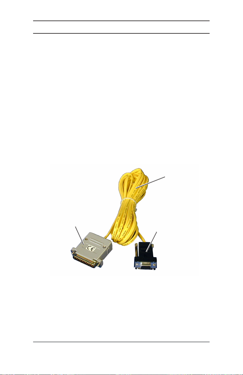
Figure 1-1 SW Communications Adapter (SWCA) .................................1
Figure 2-1 SW Inverter/Charger Remote Port Location .......................... 3
Figure 2-2 SWCAs in Multiple-Inverter Installations ............................. 6
Figure 2-2a Enlargement of Pin Assignments and Color Coding
Figure 2-2b Enlargement of Pin Assignments and Color Coding
Figure 2-2c Enlargement of Pin Assignments and Color Coding
Figure 3-1 Virtual Display using DOS Emulation Program ................... 9
Figure 3-2 SWCA Programming Menu Display.................................... 10
Figure 3-3 Making a New Connection ................................................... 16
Figure 3-4 Telephone Number Dialog Box ............................................ 17
Figure 3-5 Com 1 Properties ................................................................... 18
on Custom-made Serial Port Adapter ............................... 7
for 25-foot (4-conductor, telephone standard) Cable ..... 7
on SWCA Adapter ............................................................... 7
vi
©2002 Xantrex Technology Inc.
P/N 973-0022-01-01 Rev A 04/2002

List of Tables
Table 3-1 The SWCA Programming Menu ...........................................11
Table 3-2 LED Control Indicator Definitions ....................................... 12
Table 3-3 Keyboard Commands for using Terminal
Table 4-1 Troubleshooting the SWCA .................................................. 21
Emulation Programs ......................................................... 14
©2002 Xantrex Technology Inc.
P/N 973-0022-01-01 Rev A 04/2002
vii

viii
©2002 Xantrex Technology Inc.
P/N 973-0022-01-01 Rev A 04/2002
1.0 INTRODUCTION
The Sine Wave Communications Adapter (SWCA) allows any SW series
inverter/charger to be connected to a computer serial port or directly to a modem to
be controlled and monitored over long distances.
The SWCA package includes the following items:
• SWCA adapter (gray plastic housing with green LED, phone jack and a
25-pin connector)
• Custom-made Serial Port Adapter (black plastic housing with phone jack and
9-pin connector)
• 25-foot, 4-conductor phone cable (with RJ11 jack tabs on the same side of
the cable)
• 3.5" floppy disk with DOS program SWCPS.EXE (simulates the inverters
control panel)
• SWCA Owner’s Manual
Please be sure all of these parts are included before trying to use the SWCA.
Phone Cable
SWCA
Adapter
SW Communications Adapter (SWCA)
©2002 Xantrex Technology Inc.
P/N 973-0022-01-01 Rev A 04/2002
Figure 1-1
Custom-Made
Serial Port Adapter
1

2
©2002 Xantrex Technology Inc.
P/N 973-0022-01-01 Rev A 04/2002
2.0 INSTALLATION
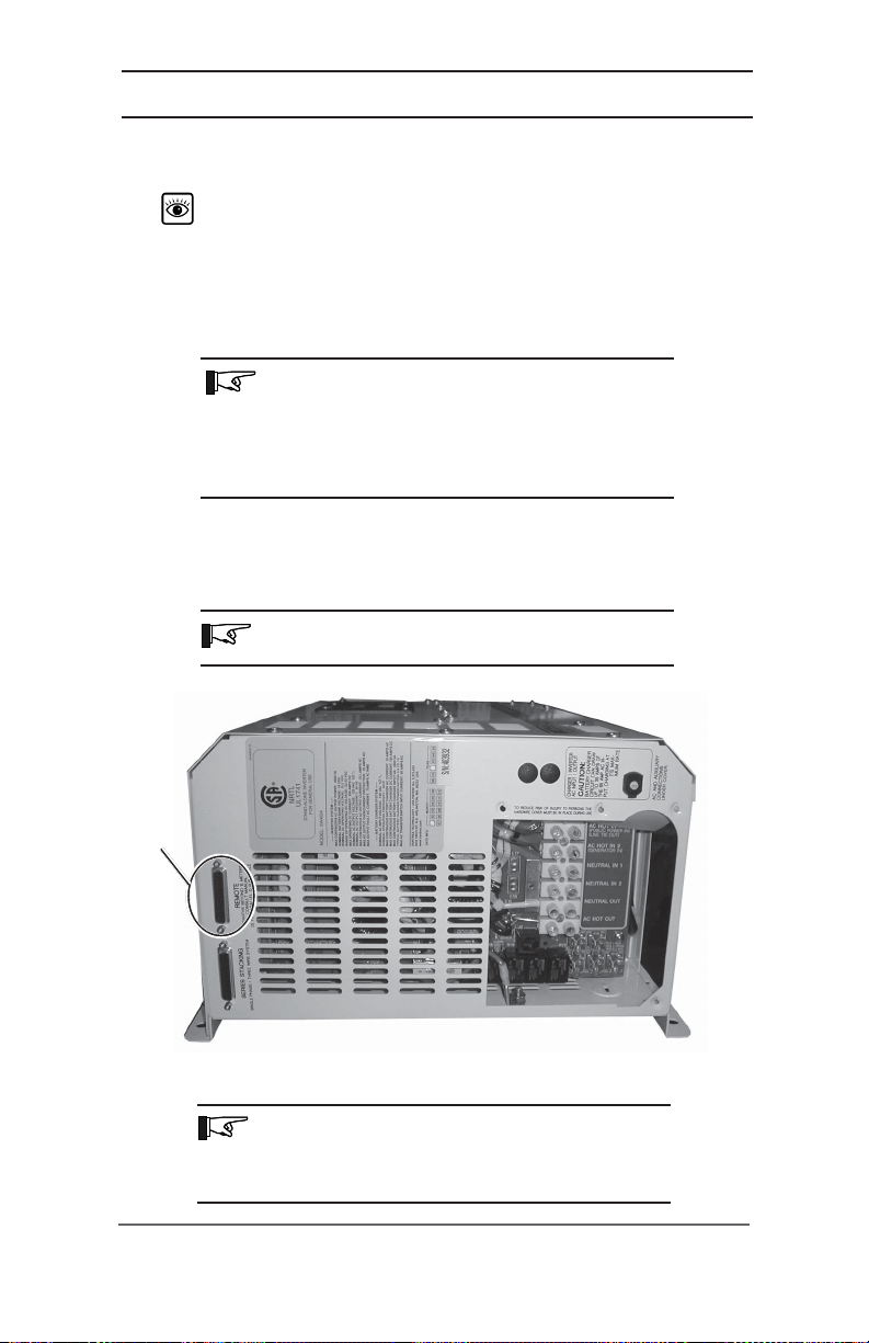
The SWCA converts the REMOTE port on the SW series inverter/charger into a
standard RS232 type communications port interface.
See Figure 2-1 for the location of the REMOTE PORT on the SW inverter/
charger.
TO INSTALL THE SWCA
1. Connect the SWCA adapter to the SW series inverter/charger
located on the left end of the inverter, near the AC wiring compartment.
NOTE: There are two ports located on the inverter – one
is used for the stacking cable and the other is for the
remote control port. Make sure you connect the SWCA to
the correct port. If a SW series remote control is being
used, it will have to be disconnected while the SWCA is
in use.
2. Connect the phone cable to the phone jack on the gray SWCA housing and to
the black serial port adapter.
3. Plug the serial port adapter into the computer serial port.
NOTE: On some computers, a DB9-to-DB25 adapter
may be needed to allow connection.
remote
port
Remote
Port
SW Inverter/Charger Remote Port Location
NOTE: The location of the REMOTE PORT may vary
slightly depending upon the model of SW inverter/charger
being used. All models should be labeled, however, to
simplify the identification and location of the port.
©2002 Xantrex Technology Inc.
P/N 973-0022-01-01 Rev A 04/2002
Figure 2-1
3

2.0 INSTALLATION
Connecting the SWCA to a Computer using a Modem
The SWCA can be connected directly to a modem for use in remote sites
where a computer may not be available.
Requirements
To use a modem, the following is required:
• a terminal emulation program,
See
SECTION 3.0 OPERATION, Use of the SWCA with Terminal
Emulation Programs
• a modem capable of auto answer and supporting a 9600 baud connection,
• an adapter for the DB9 connection from the phone cable to serial port adapter,
•a
NULL MODEM
modem provider and modem documentation for more information.
Additional Possible Requirements
The modem at the inverter location might need to be DC powered if it is
necessary to connect to the inverter during a fault condition where the inverter has
shut off its AC output.
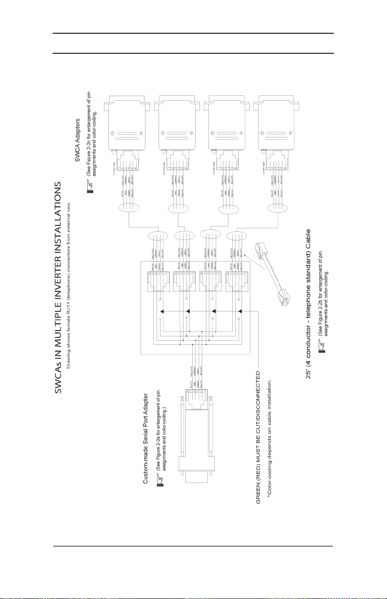
Connecting Multiple SWCAs to a Single Computer
Up to eight SWCAs can be used with a single computer serial port. The phone
cable four conductors are simply run in parallel using standard phone cable line
“splitters”. The splitters must connect the wires of the same color together – do not
switch the colors around.
Before connecting multiple adapters to a serial port, connect each adapter
individually to ensure it operates properly. The adapter ID number must be changed
by using the DOS program provided on the disk before they are connected to the
same computer serial port. The ID number can only be changed with a single
adapter connected to the computer’s serial port.
.
adapter will be required for most applications. Contact the
4
©2002 Xantrex Technology Inc.
P/N 973-0022-01-01 Rev A 04/2002

2.0 INSTALLATION
Advanced Monitoring Software
The SWCA was developed to change the SW inverter raw data output to an
RS232 protocol output. The SWCA code only manipulates the inverter’s display
or remote (SWRC) keypad strokes. The included DOS software emulates these
keystrokes.
There are companies that have used these keystroke’s bits of information
(coming out of the SWCA) to develop advanced monitoring software. This
software can provide monitoring and data logging capability. Additional
information on these programs can be found at www.righthandeng.com or
www.mauisolarsoftware.com.
NOTE: Xantrex Technology Inc. assumes no
responsibility for the use or function of these advanced
monitoring software programs.
INSTALLATION CONCERNS
Multiple SWCAs
If using multiple SWCAs and multiple inverters, the green wire must be
isolated from each other as shown in Figure 2-2 on page 6.
NOTE: This could be a red wire - depending on the cable
installation from the SWCA).
Positive Ground or PV Ground Fault Protection Installations
When using the SWCA in inverter installations that have DC ground fault
protection (PVGFP) or where the inverter is connected in a “positive ground”
configuration, it is recommended that an opto-isolator be connected somewhere
between the SWCA and the computer com port. Opto-isolators can be obtained
through www.blackbox.com (part SP400A-R3 and PS576 - 9Vdc power supply).
©2002 Xantrex Technology Inc.
P/N 973-0022-01-01 Rev A 04/2002
5
2.0 INSTALLATION
Installation Concerns (continued)
SWCAs in Multiple-Inverter Installations
6
Figure 2-2
©2002 Xantrex Technology Inc.
P/N 973-0022-01-01 Rev A 04/2002
2.0 INSTALLATION
6
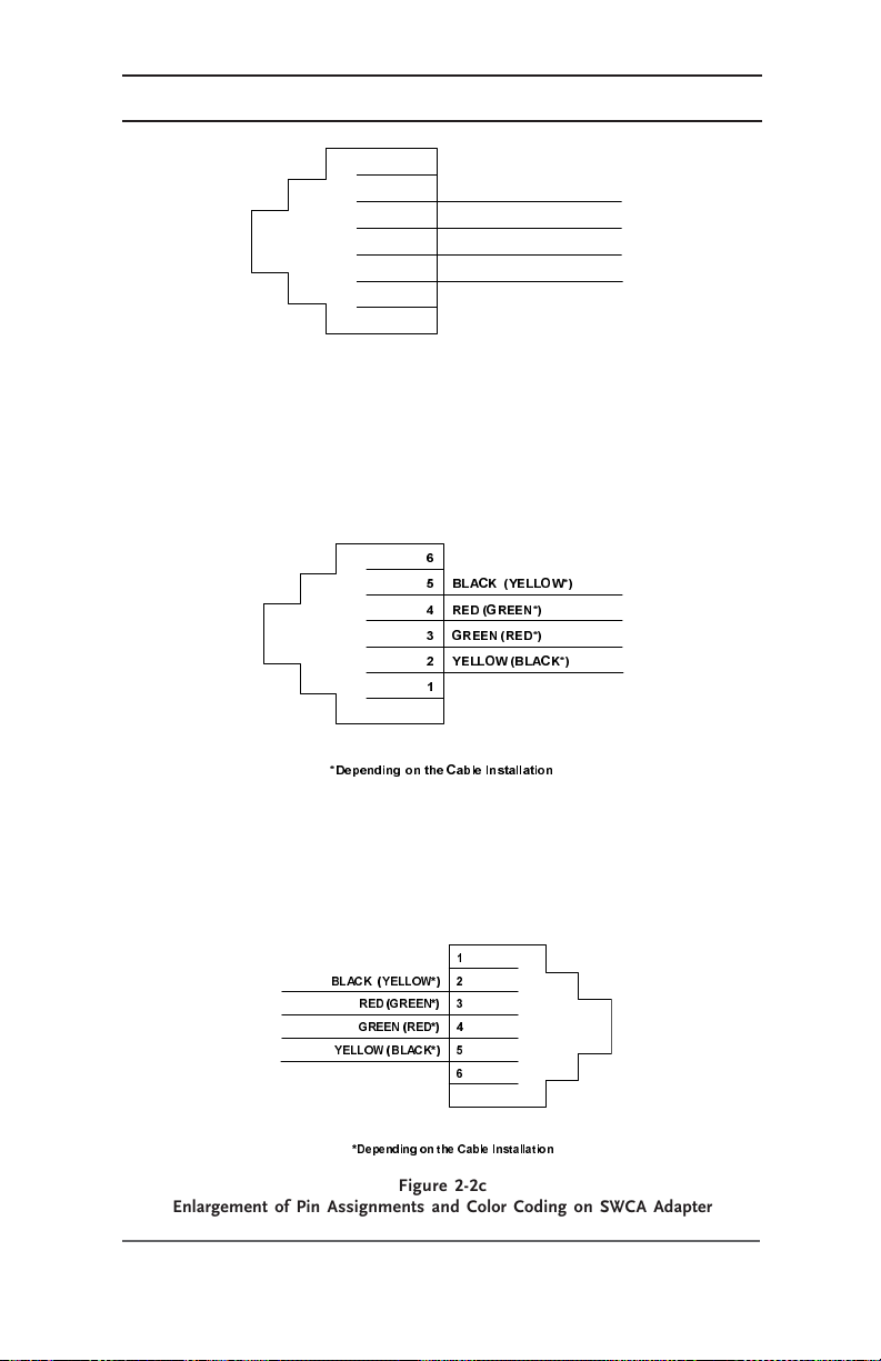
5
BLACK (YELLOW*)
4
RED (GREEN*)
3
GREEN (RED*)
2
YELLOW (BLACK*)
1
*Depending on th e C able Installation
Enlargement of Pin Assignments and Color Coding
on Custom-made Serial Port Adapter
Figure 2-2a
%/$&.<(//2:
5('*5((1
*5((15('
<(//2:%/$&.
'HSH QGLQJRQWKH&DEOH ,QVWDOODWLRQ
Figure 2-2b
Enlargement of Pin Assignments and Color Coding
for 25-foot (4-conductor, telephone standard) Cable
%/$&.<(//2:
5('*5((1
*5((15('
<(//2:%/$&.
'HSHQGLQJRQWKH&DEOH,QVWDOODWLRQ
Figure 2-2c
Enlargement of Pin Assignments and Color Coding on SWCA Adapter
©2002 Xantrex Technology Inc.
P/N 973-0022-01-01 Rev A 04/2002
7

2.0 INSTALLATION
INSTALLING THE SWCPS DOS PROGRAM
A control panel simulation software program included on the floppy disk allows
an IBM-compatible personal computer to operate as a virtual control panel for up to
eight SW series inverter/chargers.
For other computer platforms, See
SWCA with Terminal Emulation Programs
To install the software, insert the floppy disk into your computer floppy drive
and copy the file
computer. Remember the location of this file on the hard disk for later reference.
Alternately, the program can be run directly from the floppy disk.
swcps.exe
from the floppy disk provided to the hard disk on the
SECTION 3.0 OPERATION, Use of the
, on page 9.
8
©2002 Xantrex Technology Inc.
P/N 973-0022-01-01 Rev A 04/2002

3.0 OPERATION
USING THE SWCPS DOS PROGRAM
This section describes the operation of the SWCPS DOS program.
SWCA DOS Display Emulation Software
Virtual Control Panel
7UDFH6:6HULHV)URQW3DQHO6LPXODWRU'269HUVLRQ
6HW,QYHUWHU
2))65&+21&+*
$'$37(5
0(18,7(0
))
F 75 $&((1*,1((5,1 * , 1& $UOLQJWRQ: $ 86 $
6(732,176
))
$&*22'
0(18+($',1*6
))
)/2$7
&203257
*(1)212))
)
Figure 3-1
Virtual Display using DOS emulation program
The DOS software program allows an IBM compatible personal computer to
operate as a virtual control panel for up to eight SW series inverter/chargers. As
shown in Figure 3-1, the function keys on the computer are the key to operating the
inverter using the software. They act as the up and down arrow keys for each
different function of the inverter just as the up and down arrow keys do on the
inverter. The screen graphically displays which keys perform which functions.
Since the display mimics the inverter, operation is very easy for anyone already
familiar with the SW series controls.
NOTE: If the adapter is plugged into the inverter after
the inverter is already on, the computer “LCD” display
may be blank until a key is pressed on the computer or
the inverter itself. The textual LED indicators on the
computer will work normally. If you are new to the SW
series inverters, reading the owner’s manual in full will
ensure getting the most from the system.
To the right of the “LCD” display is a representation of the inverter’s LED
(lighted) status indicators. All status functions shown by the inverter’s LED’s are
displayed on the screen. The only difference is that the computerized display
does not show the status lights – it shows words that represent each function.
When an LED status light on each unit is flashing, the word or words on the
computer version will flash also.
©2002 Xantrex Technology Inc.
P/N 973-0022-01-01 Rev A 04/2002
9

3.0 OPERATION
Function Keys and Other Displays
On the virtual control panel simulation, the buttons of the real control panel
have been replaced with labels shown as F1 through F10. These refer to the function
keys of the computer keyboard which are located either above or next to the main
keyboard area. Each function key is associated with a specific inverter operation.
Pressing the appropriate function key causes the display on both the inverter and the
PC screen to change accordingly.
The virtual control panel also shows the LCD display window on the inverter’s
control panel. This will show the same information that is available at the inverter.
When no adapter is available, the text “ADAPTER OFFLINE” appears. When an
SWCA has been successfully connected, the LCD display window of the control panel
simulator shows what is displayed on the inverter LCD display (e.g., adapter 3).
To the right of the LCD display area on the control panel simulator is an area
where the status of the inverter’s LED indicators are displayed. Any active LEDs are
displayed by the label description of the LEDs function being shown. If the LED is
flashing on the inverter, then the label description of the LED will also flash on the
control panel simulator.
Since the same menu system is used with the control panel simulator as with
the inverter itself, the operation of the SWCA will be familiar to anyone who has
programmed a SW series inverter/charger system. The only difference is the use of
the function keys instead of the buttons.
The SWCA Programming Menu
The SWCA Programming Menu provides the means to change the SWCA ID
number or for changing the adapter’s configuration code. It also provides the
means for applying a textual identification labels.
Below the “LCD” display on the computer version, the word “ADAPTER”
appears. This shows which inverter is being accesssed. To access the different
inverters, simply enter the ID number of the inverter (1-8) that you want to control
by using the computer’s numeric keys.
6LQH:DYH&RPPXQLFDWLRQV0HPRU\$GDSWHU352*5$00,1*0(18
$GDSWHU,'1XPEHU
&RQILJXUDWLRQ$
&RQILJXUDWLRQ%
6HULDO1XPEHU
6RIWZDUH,'6:&$9HU
&XVWRPHU,'
67$7862.
3UHVV(6&!WRUHWXUQWR6:)URQW3DQHO6LPXODWLRQ
Figure 3-2
SWCA Programming Menu Display
10
)! 1HZ$GDSWHU,'
)! 1HZ&RQILJXUDWLRQ
)! 1HZ&XVWRPHU,'
©2002 Xantrex Technology Inc.
P/N 973-0022-01-01 Rev A 04/2002

The SWCA Programming Menu Function Keys
Programming features are accessed by pressing
function keys as described in Table 3-1.
yeK esopruP
3.0 OPERATION
ALT+P
and by using the
.8otpurebmunynaot
1F
.reisaeretpada
2F
."60"foeulav
3F
SCE
The SWCA Programming Menu
NOTE: If the program does not find an adapter it
indicates a
cable for proper connection and retry the program.
Table 3-1
TIMEOUT ERROR
.retpadaehtfonoitacifitnedi
. Check the adapter and
1fotluafedehtmorfrebmunDIACWSsegnahC
sretpadaehtetirw,rebmunDIehtgnignahcretfA
s'retpadaehtfoedistuoehtnorebmunDIwen
ehtfonoitacifitnediretalekamotgnisuohyarg
sihT.edocnoitarugifnocs'retpadaehtsegnahC
.retpadaehtfonoitarepoehtsretla
tluafedehtmorfedocsihtegnahctonoD
retalwollaotgnirtstxetynanignipytroF
.>retnE<sserpdnanoitamrofniderisedniepyT
.unemgnimmargorpehtsevaeL
©2002 Xantrex Technology Inc.
P/N 973-0022-01-01 Rev A 04/2002
11

3.0 OPERATION
LED Control Indicators
The codes indicate the status of the inverter’s LEDs. The two letter codes are
as follows:
noitaiverbbA noitinifeD
NIgnitrevnI
TLeiTeniL
1ANI1CA
2ANI2CA
KBkluB
LFtaolF
RErorrE
COtnerruCrevO
LED Control Indicator Definitions
If no codes display, it is because there are no LEDs on or the adapter is not
responding.
NOTE: If an LED is flashing, it may not appear each time
you pressed “1” because it was not illuminated when the
SWCA sent the data to the computer. A flashing o LED
should be indicated by the LED two letter code being
repeated on the display.
12
Table 3-2
©2002 Xantrex Technology Inc.
P/N 973-0022-01-01 Rev A 04/2002

3.0 OPERATION
Keyboard Commands
The following keystrokes enable navigation through the menus and provide
the means to change available settings.
ekortsyeK noitcnuF
8-1
L–sgnidaeHuneM
R+sgnidaeHuneM
U)potsdrawot(–emtIuneM
D)mottobsdrawot(+emtIuneM
_ro-)eulavrewol(–tnioPteS
=ro+)eulavrehgih(+tnioPteS
I
G
>S<>lrtC<
/ro?sutatSDEL
:retrevnitceleS
.tluafedehtsi1.rebmunDIs'retrevniehtsi8hguorht1
uneMFFO/nOretrevnI
)lenaplortnocretrevniehtnonottubDERehtsaemas(
uneMFFO/nOrotareneG
lortnocretrevniehtnonottubNEERGehtsaemas(
)lenap
uneMputeS
ehttauneMFFO/nOdnarotareneGgnihsupsaemas(
)emitemas
VACWSforebmunnoisreV
T
Keyboard Commands for using Terminal Emulation Programs
©2002 Xantrex Technology Inc.
P/N 973-0022-01-01 Rev A 04/2002
edomlanimretteS
gniyrt,yalpsidsretcarahcegnartsfostoleesuoyfI
.edomlanimretrof"T"gnisserp
Table 3-3
13
3.0 OPERATION
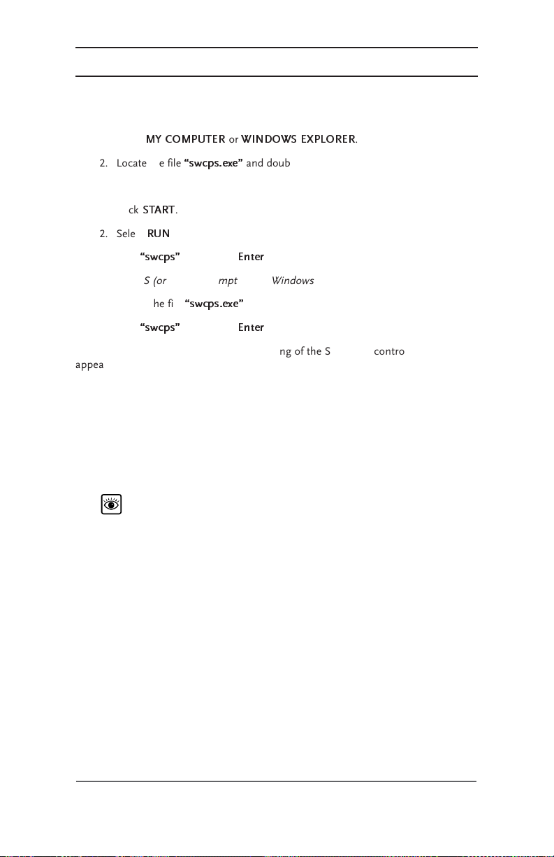
Starting the Program
From Windows:
1. Open
2. Locate the file
or
1. Click
2. Select
3. Type
From DOS (or a DOS prompt within Windows):
1. Locate the file
2. Type
When the program starts, a line drawing of the SW series control panel will
appear on the computer screen. You can resize the MSDOS window for better
viewing of the control panel if the labeling is not clear.
ID Numbers
Once the program has started, it looks for an SWCA programmed with an
ID number of “1”. This is the default ID number of all adapters. If two adapters
are connected to a PC with the same ID number, you will not be able to
communicate with either until the adapters have different ID numbers.
The program also assumes that the SWCA is connected to a serial port with
a COM number of 1. If you are using a COM port other than one, refer to the
paragraph in this section titled
MY COMPUTER
swcps.exe
START
.
RUN
.
swcps
and press <
swcps.exe
swcps
and press <
Refer to Table 3-1 on page 11 for information on accessing the SWCA
Programming Menu to reprogram the adapters with a different ID number.
or
WINDOWS EXPLORER
and double-click it.
Enter
>.
.
Enter
>.
.
Changing the PC’s COM Port Number
.
Changing the PC’s COM Port Number
To change the COM port number that the control panel simulator DOS
program uses to find the adapter, add the COM port ID number (1-4) after the
DOS command used to start the SWCPS program as follows:
C:> SWCPS 2
This command causes the program to look at the COM 2 port on the PC for
the SWCA adapters.
14
©2002 Xantrex Technology Inc.
P/N 973-0022-01-01 Rev A 04/2002

3.0 OPERATION
Accessing HELP Information from the SWCPS Program
Help is available while using the SWCPS program by pressing F10 on the
computer keyboard.
To leave the help screen, press the
simulation program.
Accessing the SETUP MENU from the SWCPS Program
To access the inverter
available for inverters with Rev 4.01 and higher software versions.
To leave the
main menu display.
SETUP MENU
SETUP MENU
, press F7 which returns you to the
Switching Between Multiple SWCA Adapters/inverters
To select another inverter, simply press the number key for the SWCA
adapter that was programmed in and written on the outside of the adapter as
previously discussed. Use numbers from 1 to 8.
Exiting the SWCPS Program
To exit the SWCPS program, press ALT-X. You can also use the ESC key to
quit as well.
ESC
key to return to control panel
, press ALT-F8 together. This feature is
SET INVERTER
©2002 Xantrex Technology Inc.
P/N 973-0022-01-01 Rev A 04/2002
15

3.0 OPERATION
USE OF THE SWCA WITH TERMINAL EMULATION PROGRAMS
Modem connection requires the use of a terminal emulation program as
described in the following sections. A modem is required at both the inverters
and at the computer, with a phone line available to make the connection.
The SW Communications Adapter (SWCA) supports use with “terminal
emulation” programs. Any computer that has available serial communications port
and terminal emulation software can communicate with the SW series inverter
using a cable and modem connection.
Making a New Connection
1. Start the terminal emulation software of your choice.
2. Enter “SWCA” in the Name location.
3. Select the desired icon.
4. Click “OK”.
16
Figure 3-3
Making a New Connection
©2002 Xantrex Technology Inc.
P/N 973-0022-01-01 Rev A 04/2002

3.0 OPERATION
Use of the SWCA with Terminal Emulation Programs (continued)
Establishing the Connection
1. Enter Country code: (e.g., United States of America (1))
2. Enter Area code: (e.g., 360)
3. Enter Phone Number: (e.g., 435-8826)
4. For connections to the SWCA with a cable, select “Direct to COM1”.
(If you are using a port other than COM1, choose the com port you are
using.)
5. For connections to the SWCA with a modem, select “xxx Bps Data Fax
Modem” (where “xxx” is the transmission speed of the modem being used.
6. Click OK.
Telephone Number Dialog Box
©2002 Xantrex Technology Inc.
P/N 973-0022-01-01 Rev A 04/2002
Figure 3-4
17

3.0 OPERATION
COM Port Values
You need to enter the following values for the COM port as shown in
Figure 3-5.
Bits per second: 9600 BAUD
Data bits: 8
Parity: No or None
Stop Bits: 1
Flow control: Either setting
NOTE: These are the only acceptable values
Click OK and a blank window opens.
18
Figure 3-5
COM1 Properties
©2002 Xantrex Technology Inc.
P/N 973-0022-01-01 Rev A 04/2002

3.0 OPERATION
TESTING THE SWCA
In order to test the SWCA, it must be plugged it into an inverter that is
powered up on batteries or a suitable power supply. Press the number “1”. If
everything is correct, the inverter should reply with a “UNIT1” and possibly some
two character codes.
©2002 Xantrex Technology Inc.
P/N 973-0022-01-01 Rev A 04/2002
19

3.0 OPERATION
20
©2002 Xantrex Technology Inc.
P/N 973-0022-01-01 Rev A 04/2002

motpmyS noitadnemmoceR
4.0 TROUBLESHOOTING
otgniyrterauoyretpadaehtforebmunDIehtkcehC.1
erehtnehwyalpsidlliwsihT.tcerrocsitierusnE.ssecca
.gniretneerauoyrebmunDIehthtiwretpadaonsi
:sdaeryalpsiD
ENILFFORETPADA
nehwdeyalpsidsisihT
retpadaonsiereht
.esnopser
.elbazingocer
.trop
yalpsidSODehtgninnur
nehwmargorpnoitalume
tonsi)medomaiv(ataD
gnitcennoctonsimedoM
.tropetomer
.retpadAACWSehtnoDELehtkcehC.4
.0069tadexifsimargorp
.tcerrocera
etomerehtotretpadaehtmorfnoitcennocehtkcehC.2
ehtottroPMOCehtmorfnoitcennocehtkcehC.3
s'retrevniehtotdetcennocnehwsetanimullitifI.a
.dezingocersiretpadaehtneht,tropetomer
ehtotdetcennocnehwetanimullitonseodtifI.b
siretpadaehtneht,tropetomers'retrevni
.decalperebotsdeendnagninoitcnuflam
pu-laidehtdnamedomehtrofetarDUABehterusnE
ehtfienimretedotmargorpnoitalumeSODehtnuR
retpadaehtotsnoitcennoclladnagninoitcnufsiretpada
Table 4-1
Troubleshooting the SWCA
©2002 Xantrex Technology Inc.
P/N 973-0022-01-01 Rev A 04/2002
21

4.0 TROUBLESHOOTING
22
©2002 Xantrex Technology Inc.
P/N 973-0022-01-01 Rev A 04/2002

APPENDIX A – PRODUCT AND SYSTEM INFORMATION
WARRANTY
Xantrex Technology Inc., warrants its power products against defects in
materials and workmanship for a period of two (2) years from the date of purchase,
established by proof of purchase or formal warranty registration, and extends this
warranty to all purchasers or owners of the product during the warranty period.
Xantrex does not warrant its products from any and all defects:
• arising out of material or workmanship not provided by Xantrex or its
Authorized Service Centers;
when the product is installed or exposed to an unsuitable environment as
evidenced by generalized corrosion or biological infestation;
resulting from abnormal use of the product, alteration, or use in violation of
the instructions;
• in components, parts, or products expressly warranted by another manufacturer.
Xantrex Technology Inc., agrees to supply all parts and labor to repair or replace
defects covered by this warranty with parts or products of original or improved
design, at the company's option. Xantrex Technology Inc., also reserves the right to
improve the design of its products without obligation to modify or upgrade those
previously manufactured. Defective products must be returned to Xantrex
Technology Inc., or its Authorized Service Center in the original packaging or
equivalent. The cost of transportation and insurance on items returned for service is
the responsibility of the customer. Return transportation (UPS Ground or
equivalent) as well as insurance on all repaired items is paid by Xantrex Technology
Inc.
All remedies and the measure of damages are limited to the above. Xantrex
Technology Inc., shall in no event be liable for consequential, incidental, contingent,
or special damages, even if Xantrex Technology Inc., has been advised of the
possibility of such damages. Any and all other warranties, expressed or implied,
arising by law, course of dealing, course of performance, usage of trade or otherwise,
including, but not limited to, implied warranties of merchantability and fitness for a
particular purpose, are limited in duration for a period of two (2) years from the
original date of purchase.
Some states or countries do not allow limitations on the term of an implied
warranty, or the exclusion or limitation of incidental or consequential damage, which
means the limitations and exclusions of this warranty may not apply to you. Even
though this warranty gives you specific legal rights, you may also have other rights
which vary from state to state.
©2002 Xantrex Technology Inc.
P/N 973-0022-01-01 Rev A 04/2002
A-1

APPENDIX A – PRODUCT & SYSTEM INFORMATION
RETURN MATERIAL AUTHORIZATION POLICY
You must obtain a Return Material Authorization (RMA) number from Xantrex
before returning a product directly to Xantrex. Products returned without an RMA
number or shipped collect will be refused. When you contact Xantrex to obtain
servcie, be prepared to supply the serial number of your product and its date of
purchase as well as information about the installation and use of the unit. Record
this information in “Information About Your System” on page A-3 of this guide.
RETURN MATERIAL PROCEDURE
If you are returning a product, follow this procedure:
1. Obtain an RMA number and a shipping address from Xantrex.
2. Package the unit safely, preferably using the original box and packing
materials. Include the following:
• The RMA number
• A copy of your dated proof of purchase
• A return address where the repaired unit can be shipped
• A contact telephone number
• A brief description of the problem
3. Ship the unit freight prepaid to the address provided in step 1.
A-2
©2002 Xantrex Technology Inc.
P/N 973-0022-01-01 Rev A 04/2002

APPENDIX A – PRODUCT & SYSTEM INFORMATION
SERVICE INFORMATION
Xantrex Technology Inc. takes great pride in its products and makes every effort
to ensure your unit fully meets your independent powering needs.
If your product needs repair, contact our Customer Service department at:
(360) 435-8826 to obtain an RMA# and shipping information; or, fax this page with
the following information to: (360) 474-0616.
Please provide:
Part Number: _______________________________________
Purchase Date: _____________________________________
Problem: ___________________________________________
Include a telephone number where you can be reached during business hours
and a complete return shipping address (P.O. Box numbers are not acceptable).
Name: _______________________________________________
Address: _____________________________________________
City: ________________________________________________
State / Province: _______________________________________
Zip / Postal Code: _____________________________________
Country: _____________________________________________
Phone: (____) _________________________________________
FAX: (____) __________________________________________
E-mail Address: _______________________________________
©2002 Xantrex Technology Inc.
P/N 973-0022-01-01 Rev A 04/2002
A-3

APPENDIX A – PRODUCT & SYSTEM INFORMATION
Notes:
A-4
©2002 Xantrex Technology Inc.
P/N 973-0022-01-01 Rev A 04/2002


t
1 360 435 8826
f
1 360 435 2229
dpm@xantrex.com
www.xantrex.com
P/N 973-0022-01-01 Rev A Printed in USA
 Loading...