

by
Conext™ ComBox
Communication and
Monitoring Device
For Freedom SW Series of Products
Owner’s Guide
www.xantrex.com

Copyright and Contact
Copyright © 2013 Schneider Electric. All Rights Reserved. All trademarks are owned by Schneider Electric Industries
SAS or its affiliated companies.
Exclusion for Documentation
U
NLESS SPECIFICALLY AGREED TO IN WRITING, SELLER
(A) MAKES NO WARRANTY AS TO THE ACCURACY, SUFFICIENCY OR SUITABILITY OF ANY TECHNICAL OR OTHER INFORMATION PROVIDED
IN ITS MANUALS OR OTHER DOCUMENTATION;
(
B) ASSUMES NO RESPONSIBILITY OR LIABILITY FOR LOSSES, DAMAGES, COSTS OR EXPENSES, WHETHER SPECIAL, DIRECT, INDIRECT,
CONSEQUENTIAL OR INCIDENTAL, WHICH MIGHT ARISE OUT OF THE USE OF SUCH INFORMATION. THE USE OF ANY SUCH INFORMATION
WILL BE ENTIRELY AT THE USER’S RISK; AND
(C) REMINDS YOU THAT IF THIS MANUAL IS IN ANY LANGUAGE OTHER THAN ENGLISH, ALTHOUGH STEPS HAVE BEEN TAKEN TO
MAINTAIN THE ACCURACY OF THE TRANSLATION, THE ACCURACY CANNOT BE GUARANTEED. APPROVED CONTENT IS CONTAINED WITH
THE ENGLISH LANGUAGE VERSION WHICH IS POSTED AT WWW.SCHNEIDER-ELECTRIC.COM.
Document Number: 975-0704-01-01 Revision: Revision A Date: January 2014
Product Part Number: 809-0918
Contact Information www.xantrex.com
Information About Your System
As soon as you open your product, record the following information and be sure to keep your proof of purchase.
Serial Number
Product Number
Purchased From
Purchase Date
_________________________________
_________________________________
_________________________________
_________________________________

About This Guide
Purpose
The purpose of this Owner’s Guide is to provide explanations and procedures for
installing, operating, configuring, maintaining, and troubleshooting the Conext
ComBox Communication and Monitoring Device for Freedom SW inverter/
chargers and accessories.
Scope
The Guide provides safety guidelines, planning, and setup information,
procedures for installing the Conext ComBox, as well as information about
configuring, monitoring, and troubleshooting the unit. It does include information
on how to use other Xantrex products.
Firmware Revision
Some Conext ComBox features and functions described in this guide may be
incorporated with later firmware versions. This manual is valid for Conext
ComBox – Freedom SW version 01.00 and above. To view the firmware version
on your product, see the Conext ComBox Status Information in the web user
interface.
Audience
Organization
The Guide is intended for use by anyone who plans to construct, install, or
operate a system involving the Conext ComBox–Freedom SW. The information in
this manual is intended for qualified personnel. Qualified personnel have training,
knowledge, and experience in:
• Installing electrical equipment
• Applying all applicable installation codes
• Analyzing and reducing the hazards involved in performing electrical work
• Changing any TCP/IP-related settings
This Guide is organized into five chapters and an appendix.
Chapter 1, “Overview”, describes physical features of the Conext ComBox and
introduces the user interface.
Chapter 2, “Installation”, describes how to install, wire, and connect the Conext
ComBox to your network.
Chapter 3, “Configuration”, describes how to configure and change device
settings, manage data logs, import and export data, and upgrade firmware.
Chapter 4, “Monitoring”, describes how to monitor LED indicator lights (LEDs),
system and device levels, and create historical views.
Chapter 5, “Troubleshooting”, describes how to interpret events and alerts.
975-0704-01-01 Revision A iii
About This Guide
DANGER
WARNING
CAUTION
NOTICE
Conventions Used
Appendix A, “Specifications”, contains the electrical, mechanical and
environmental specifications for the Conext ComBox.
The following conventions are used in this guide.
DANGER indicates an imminently hazardous situation, which, if not avoided,
will result in death or serious injury.
WARNING indicates a potentially hazardous situation, which, if not avoided,
can result in death or serious injury.
CAUTION indicates a potentially hazardous situation, which, if not avoided,
can result in moderate or minor injury.
NOTICE indicates important information that you need to read carefully.
Abbreviations and Acronyms
DHCP - Dynamic Host Configuration Protocol
LED - Light Emitting Diode (used for indicator lights)
SELV - Safety Extra Low Voltage
SNTP - Simple Network Time Protocol
TCP/IP - Transmission Control Protocol/Internet Protocol
iv 975-0704-01-01 Revision A

Related Information
About This Guide
Related Products
For more information about related products, refer to:
Freedom SW Inverter/Charger Owner’s Guide
Xanbus Automatic Generator Start Owner’s Guide
Xanbus System Control Panel Owner’s Guide
Freedom Sequence Owner’s Guide
You can find more information about Xantrex products and services at
www.xantrex.com.
975-0704-01-01 Revision A v

vi

Contents
Important Safety Instructions
1 Overview
Compatible Xanbus™ Components - - - - - - - - - - - - - - - - - - - - - - - - - - - - - - - - - - - - - - - - - - - - 1–2
Physical Features - - - - - - - - - - - - - - - - - - - - - - - - - - - - - - - - - - - - - - - - - - - - - - - - - - - - - - - - - 1–3
Data Ports and Reset Button - - - - - - - - - - - - - - - - - - - - - - - - - - - - - - - - - - - - - - - - - - - - - - 1–3
LED Indicator Lights (LEDs) - - - - - - - - - - - - - - - - - - - - - - - - - - - - - - - - - - - - - - - - - - - - - - - 1–4
Communication and Power Ports - - - - - - - - - - - - - - - - - - - - - - - - - - - - - - - - - - - - - - - - - - - 1–5
Types of Conext ComBox Networks - - - - - - - - - - - - - - - - - - - - - - - - - - - - - - - - - - - - - - - - - - - - 1–6
Conext ComBox on a Local Area Network (LAN) - - - - - - - - - - - - - - - - - - - - - - - - - - - - - - - - 1–6
Conext ComBox with Remote Access - - - - - - - - - - - - - - - - - - - - - - - - - - - - - - - - - - - - - - - - 1–7
Power Sources for the Conext ComBox - - - - - - - - - - - - - - - - - - - - - - - - - - - - - - - - - - - - - - - - - 1–7
User Interface - - - - - - - - - - - - - - - - - - - - - - - - - - - - - - - - - - - - - - - - - - - - - - - - - - - - - - - - - - - 1–9
Home Screen - - - - - - - - - - - - - - - - - - - - - - - - - - - - - - - - - - - - - - - - - - - - - - - - - - - - - - - - 1–10
Menu Bar - - - - - - - - - - - - - - - - - - - - - - - - - - - - - - - - - - - - - - - - - - - - - - - - - - - - - - - - - - - 1–11
Conext ComBox Setup Buttons - - - - - - - - - - - - - - - - - - - - - - - - - - - - - - - - - - - - - - - - - - - 1–12
Other Buttons - - - - - - - - - - - - - - - - - - - - - - - - - - - - - - - - - - - - - - - - - - - - - - - - - - - - - - - - 1–13
System Scheduled Maintenance - - - - - - - - - - - - - - - - - - - - - - - - - - - - - - - - - - - - - - - - - - - - - 1–13
2 Installation
Choosing a Location - - - - - - - - - - - - - - - - - - - - - - - - - - - - - - - - - - - - - - - - - - - - - - - - - - - - - - - 2–2
Materials and Tools Required - - - - - - - - - - - - - - - - - - - - - - - - - - - - - - - - - - - - - - - - - - - - - - - - 2–3
Materials List - - - - - - - - - - - - - - - - - - - - - - - - - - - - - - - - - - - - - - - - - - - - - - - - - - - - - - - - - 2–3
Additional Material and Tools - - - - - - - - - - - - - - - - - - - - - - - - - - - - - - - - - - - - - - - - - - - - - - 2–3
Mounting the Conext ComBox - - - - - - - - - - - - - - - - - - - - - - - - - - - - - - - - - - - - - - - - - - - - - - - - 2–4
Wall Mount - - - - - - - - - - - - - - - - - - - - - - - - - - - - - - - - - - - - - - - - - - - - - - - - - - - - - - - - - - - 2–4
DIN Rail Mount - - - - - - - - - - - - - - - - - - - - - - - - - - - - - - - - - - - - - - - - - - - - - - - - - - - - - - - - 2–5
Wiring the RS 485 Modbus Connector for Data Communication - - - - - - - - - - - - - - - - - - - - - - - - 2–6
Wiring the Dry Contact Connector - - - - - - - - - - - - - - - - - - - - - - - - - - - - - - - - - - - - - - - - - - - - - 2–8
Wiring the Conext ComBox to an Ethernet Network - - - - - - - - - - - - - - - - - - - - - - - - - - - - - - - - - 2–9
Turning On the Conext ComBox- - - - - - - - - - - - - - - - - - - - - - - - - - - - - - - - - - - - - - - - - - - - - - 2–11
Connecting the AC/DC Power Adapter - - - - - - - - - - - - - - - - - - - - - - - - - - - - - - - - - - - - - - 2–12
Wiring the RS 485 Modbus Connector for Power to the Conext ComBox - - - - - - - - - - - - - - 2–12
975-0704-01-01 Revision A vii

Contents
Connecting to the Web Interface Using the Discovery Tool - - - - - - - - - - - - - - - - - - - - - - - - - - 2–15
Connecting to the Web Interface Using a USB Thumb Drive - - - - - - - - - - - - - - - - - - - - - - - - - 2–16
Connecting to the Web Interface Using an Android Tablet- - - - - - - - - - - - - - - - - - - - - - - - - - - 2–17
3 Configuration
Configuration Steps - - - - - - - - - - - - - - - - - - - - - - - - - - - - - - - - - - - - - - - - - - - - - - - - - - - - - - - 3–2
Logging In- - - - - - - - - - - - - - - - - - - - - - - - - - - - - - - - - - - - - - - - - - - - - - - - - - - - - - - - - - - - - - 3–3
Changing the Admin Password - - - - - - - - - - - - - - - - - - - - - - - - - - - - - - - - - - - - - - - - - - - - - - - 3–5
Changing the Time - - - - - - - - - - - - - - - - - - - - - - - - - - - - - - - - - - - - - - - - - - - - - - - - - - - - - - - - 3–7
Changing E-Mail Settings - - - - - - - - - - - - - - - - - - - - - - - - - - - - - - - - - - - - - - - - - - - - - - - - - - - 3–9
Connecting the Conext ComBox to the Xanbus Network - - - - - - - - - - - - - - - - - - - - - - - - - - - - 3–11
Changing Basic Conext ComBox Settings - - - - - - - - - - - - - - - - - - - - - - - - - - - - - - - - - - - - - - 3–13
Control Panel - - - - - - - - - - - - - - - - - - - - - - - - - - - - - - - - - - - - - - - - - - - - - - - - - - - - - - - - 3–14
Changing Advanced Conext ComBox Settings- - - - - - - - - - - - - - - - - - - - - - - - - - - - - - - - - - - 3–15
General Settings - - - - - - - - - - - - - - - - - - - - - - - - - - - - - - - - - - - - - - - - - - - - - - - - - - - - - - 3–16
Change User Password Settings - - - - - - - - - - - - - - - - - - - - - - - - - - - - - - - - - - - - - - - - - - 3–17
Change Admin Password Settings - - - - - - - - - - - - - - - - - - - - - - - - - - - - - - - - - - - - - - - - - 3–18
TCP/IP Settings - - - - - - - - - - - - - - - - - - - - - - - - - - - - - - - - - - - - - - - - - - - - - - - - - - - - - - 3–18
E-mail Settings - - - - - - - - - - - - - - - - - - - - - - - - - - - - - - - - - - - - - - - - - - - - - - - - - - - - - - - 3–19
E-mail Reporting - - - - - - - - - - - - - - - - - - - - - - - - - - - - - - - - - - - - - - - - - - - - - - - - - - - - - - 3–19
Web - - - - - - - - - - - - - - - - - - - - - - - - - - - - - - - - - - - - - - - - - - - - - - - - - - - - - - - - - - - - - - 3–21
FTP - - - - - - - - - - - - - - - - - - - - - - - - - - - - - - - - - - - - - - - - - - - - - - - - - - - - - - - - - - - - - - - 3–22
FTP Logger - - - - - - - - - - - - - - - - - - - - - - - - - - - - - - - - - - - - - - - - - - - - - - - - - - - - - - - - - 3–23
Dry Contact Relay - - - - - - - - - - - - - - - - - - - - - - - - - - - - - - - - - - - - - - - - - - - - - - - - - - - - 3–24
Suppress Device Faults/Warnings - - - - - - - - - - - - - - - - - - - - - - - - - - - - - - - - - - - - - - - - - 3–24
Xanbus Communications - - - - - - - - - - - - - - - - - - - - - - - - - - - - - - - - - - - - - - - - - - - - - - - 3–25
Modbus Communications - - - - - - - - - - - - - - - - - - - - - - - - - - - - - - - - - - - - - - - - - - - - - - - 3–25
Modbus Byte Order - - - - - - - - - - - - - - - - - - - - - - - - - - - - - - - - - - - - - - - - - - - - - - - - 3–26
Modbus Address List - - - - - - - - - - - - - - - - - - - - - - - - - - - - - - - - - - - - - - - - - - - - - - - - - - 3–27
Modbus Address Enumeration - - - - - - - - - - - - - - - - - - - - - - - - - - - - - - - - - - - - - - - - - - - 3–28
System Diagram - - - - - - - - - - - - - - - - - - - - - - - - - - - - - - - - - - - - - - - - - - - - - - - - - - - - - - 3–30
Resetting the Conext ComBox to Factory Settings - - - - - - - - - - - - - - - - - - - - - - - - - - - - - - - - 3–30
Changing Device Settings - - - - - - - - - - - - - - - - - - - - - - - - - - - - - - - - - - - - - - - - - - - - - - - - - 3–31
Using Cascading Parameters - - - - - - - - - - - - - - - - - - - - - - - - - - - - - - - - - - - - - - - - - - - - 3–34
viii 975-0704-01-01 Revision A

Upgrading Firmware - - - - - - - - - - - - - - - - - - - - - - - - - - - - - - - - - - - - - - - - - - - - - - - - - - - - - - 3–35
Clearing the Internal Firmware Memory - - - - - - - - - - - - - - - - - - - - - - - - - - - - - - - - - - - - - - 3–36
Installing Conext ComBox Upgrades from a Thumb Drive - - - - - - - - - - - - - - - - - - - - - - - - 3–37
Installing Conext ComBox Upgrades Remotely - - - - - - - - - - - - - - - - - - - - - - - - - - - - - - - - 3–39
Installing Xanbus Device Upgrades - - - - - - - - - - - - - - - - - - - - - - - - - - - - - - - - - - - - - - - - 3–41
4 Monitoring
Monitoring LEDs - - - - - - - - - - - - - - - - - - - - - - - - - - - - - - - - - - - - - - - - - - - - - - - - - - - - - - - - - - 4–2
Startup - - - - - - - - - - - - - - - - - - - - - - - - - - - - - - - - - - - - - - - - - - - - - - - - - - - - - - - - - - - - - - 4–2
Operating Mode - - - - - - - - - - - - - - - - - - - - - - - - - - - - - - - - - - - - - - - - - - - - - - - - - - - - - - - 4–3
Monitoring Conext ComBox Status Information - - - - - - - - - - - - - - - - - - - - - - - - - - - - - - - - - - - - 4–3
Monitoring System Components - - - - - - - - - - - - - - - - - - - - - - - - - - - - - - - - - - - - - - - - - - - - - - 4–6
Devices - - - - - - - - - - - - - - - - - - - - - - - - - - - - - - - - - - - - - - - - - - - - - - - - - - - - - - - - - - - - - 4–6
System Component Energy Graphs - - - - - - - - - - - - - - - - - - - - - - - - - - - - - - - - - - - - - - - - 4–10
Interpreting a Battery Energy Graph - - - - - - - - - - - - - - - - - - - - - - - - - - - - - - - - - - - - - 4–12
Interpreting a Load Energy Graph - - - - - - - - - - - - - - - - - - - - - - - - - - - - - - - - - - - - - - 4–13
Interpreting a Generator Energy Graph - - - - - - - - - - - - - - - - - - - - - - - - - - - - - - - - - - - 4–14
Managing Data Logs - - - - - - - - - - - - - - - - - - - - - - - - - - - - - - - - - - - - - - - - - - - - - - - - - - - - - 4–15
Accessing and Downloading Log Files - - - - - - - - - - - - - - - - - - - - - - - - - - - - - - - - - - - - - - 4–17
Contents
5 Troubleshooting
Viewing Xanbus Device Faults and Warnings - - - - - - - - - - - - - - - - - - - - - - - - - - - - - - - - - - - - - 5–2
Viewing System Events - - - - - - - - - - - - - - - - - - - - - - - - - - - - - - - - - - - - - - - - - - - - - - - - - - - - - 5–6
Viewing Faults and Warnings - - - - - - - - - - - - - - - - - - - - - - - - - - - - - - - - - - - - - - - - - - - - - - - - - 5–6
Browsing System Event and Fault Log Files - - - - - - - - - - - - - - - - - - - - - - - - - - - - - - - - - - - - - - 5–7
Browsing Energy Log Files - - - - - - - - - - - - - - - - - - - - - - - - - - - - - - - - - - - - - - - - - - - - - - - - - - 5–9
Common Solutions - - - - - - - - - - - - - - - - - - - - - - - - - - - - - - - - - - - - - - - - - - - - - - - - - - - - - - - 5–12
A Specifications
Electrical Specifications - - - - - - - - - - - - - - - - - - - - - - - - - - - - - - - - - - - - - - - - - - - - - - - - - - - -A–2
Communication Interfaces - - - - - - - - - - - - - - - - - - - - - - - - - - - - - - - - - - - - - - - - - - - - - - - - A–2
Data Interfaces - - - - - - - - - - - - - - - - - - - - - - - - - - - - - - - - - - - - - - - - - - - - - - - - - - - - - - - - A–2
Power Supply (SELV or Class 2 Power Sources) - - - - - - - - - - - - - - - - - - - - - - - - - - - - - - - - A–2
Memory - - - - - - - - - - - - - - - - - - - - - - - - - - - - - - - - - - - - - - - - - - - - - - - - - - - - - - - - - - - - -A–3
General Specifications - - - - - - - - - - - - - - - - - - - - - - - - - - - - - - - - - - - - - - - - - - - - - - - - - - - - -A–3
Features - - - - - - - - - - - - - - - - - - - - - - - - - - - - - - - - - - - - - - - - - - - - - - - - - - - - - - - - - - - - - - - A–4
Regulatory Approvals - - - - - - - - - - - - - - - - - - - - - - - - - - - - - - - - - - - - - - - - - - - - - - - - - - - - - -A–4
Schneider Electric Products that Work with the Conext ComBox - - - - - - - - - - - - - - - - - - - - - - - - A–4
Physical Dimensions - - - - - - - - - - - - - - - - - - - - - - - - - - - - - - - - - - - - - - - - - - - - - - - - - - - - - - -A–5
Front View - - - - - - - - - - - - - - - - - - - - - - - - - - - - - - - - - - - - - - - - - - - - - - - - - - - - - - - - - - -A–5
Side View - - - - - - - - - - - - - - - - - - - - - - - - - - - - - - - - - - - - - - - - - - - - - - - - - - - - - - - - - - - -A–5
Bottom View - - - - - - - - - - - - - - - - - - - - - - - - - - - - - - - - - - - - - - - - - - - - - - - - - - - - - - - - - - A–6
Back View - - - - - - - - - - - - - - - - - - - - - - - - - - - - - - - - - - - - - - - - - - - - - - - - - - - - - - - - - - -A–6
975-0704-01-01 Revision A ix

x

Important Safety Instructions
DANGER
DANGER
READ AND SAVE THESE INSTRUCTIONS - DO NOT DISCARD
This guide contains important safety instructions for the Conext ComBox
Communication and Monitoring Device for Freedom SW series of products (Part
Number 809-0918). These instructions must be followed during installation and
configuration procedures.
HAZARD OF ELECTRIC SHOCK
• Read all instructions, cautionary markings, and all other appropriate
sections of this manual before installing, operating, troubleshooting or
performing maintenance on the Conext ComBox – Freedom SW.
• Exercise extreme caution at all times to prevent accidents.
• These instructions are for use by qualified installers only.
Failure to follow these instructions will result in death or serious injury.
HAZARD OF ELECTRIC SHOCK AND FIRE
• Connect only to Safety Extra Low Voltage (SELV) circuits and power
sources.
• All wiring must be done by qualified personnel to ensure compliance with
all applicable installation codes and regulations.
• Do not expose the Conext ComBox Freedom – SW to rain, snow, spray, or
bilge water.
• Do not disassemble. No user serviceable parts inside.
• Do not install and/or operate in compartments containing flammable
materials or in locations that require ignition-protected equipment.
Failure to follow these instructions will result in death or serious injury.
975-0704-01-01 Revision A xi

Safety
NOTICE
NOTICE
EQUIPMENT DAMAGE
• All cables connected to the Conext ComBox – Freedom SW must run
indoors and not be susceptible to lightning strikes.
• Turn OFF all devices before connecting cables. The Conext ComBox does
not have an ON/OFF switch.
• Do not connect an Ethernet cable from the Conext ComBox to the WAN/
MODEM port on the network router.
• Do not connect an Ethernet cable plug into a Xanbus port on the Conext
ComBox.
• Do not connect a Xanbus RJ-45 cable plug into the 10/100 Ethernet port of
the Conext ComBox.
• Do not connect any port on the Conext ComBox to an outside line or to a
public telecommunication network.
• Ensure that the device connected on the Xanbus network is in standby
mode before changing settings. Do not change any settings unless you are
familiar with the device.
• Changes to any TCP/IP-related settings should only be performed by a
qualified IT professional.
Failure to follow these instructions can damage equipment or affect
network performance.
EQUIPMENT DAMAGE
• Do not disassemble the Conext ComBox – Freedom SW.
• See Warranty for instructions on obtaining service.
• The Conext ComBox contains no user-serviceable parts. Attempting to
service the Conext ComBox yourself will void your warranty.
Failure to follow these instructions can damage equipment.
Important: This device can be configured to connect to the Internet using portforwarding in your network router’s settings. There is a security risk in portforwarding unencrypted network traffic over a public network (Internet). Use of
a VPN or a secure tunnel to route Conext ComBox communication via the
Internet is recommended.
xii 975-0704-01-01 Revision A

1 Overview
Chapter 1 describes the features of the Conext
ComBox – Freedom SW and provides an
overview of the physical features and web user
interface.
It includes:
• Compatible Xanbus™ Components
• Physical Features
• Types of Conext ComBox Networks
• Power Sources for the Conext ComBox
• User Interface
• System Scheduled Maintenance
975-0704-01-01 Revision A 1–1

Overview
The Conext ComBox Communication and Monitoring Device (Part Number
809-0918) is an accessory compatible with the Freedom SW series of products. It
provides an overall view of system performance for mobile power monitoring
systems such as commercial, emergency and recreational vehicles, marine
vessels, construction and other heavy duty applications.
The Conext ComBox – Freedom SW lets you configure the system and devices,
monitor performance, and access data logs through a web-based application on
a PC, laptop or Android tablet.
Other features of the Conext ComBox include:
• Compatibility—connects directly to Xanbus-enabled devices
• Real-time clock—keeps time for the entire system
• Non-volatile memory—preserves the latest Conext ComBox settings if power
is interrupted or network communication is disrupted.
• Micro-SD slot—provides additional data storage.
• Firmware storage and upgrade capability—uses the Conext ComBox to
upgrade or downgrade firmware for Xanbus-enabled devices on the
network.
Important: This model of Conext ComBox is intended for connection to Freedom
SW products only, and is not compatible with other Schneider Electric inverter
products. Freedom SW products do not support grid tie or grid support functions.
Although Modbus features are available in this ComBox model, Xantrex does not
provide technical support for these features.
Compatible Xanbus™ Components
The Conext ComBox works with several Xantrex and Schneider Electric products
including:
• Freedom SW inverter/chargers
• Xanbus System Control Panel (SCP)
• Xanbus Automatic Generator Start (AGS)
• Freedom Sequence power management system
Note: For details on specific models supported, see the “Specifications”
section. The Conext ComBox supports up to a maximum of 20 devices on a
Xanbus network depending on the device types.
1–2 975-0704-01-01 Revision A
Physical Features
The following illustration shows the Conext ComBox. The tables in the following
sections contain descriptions of the connectors, indicators, and data ports.
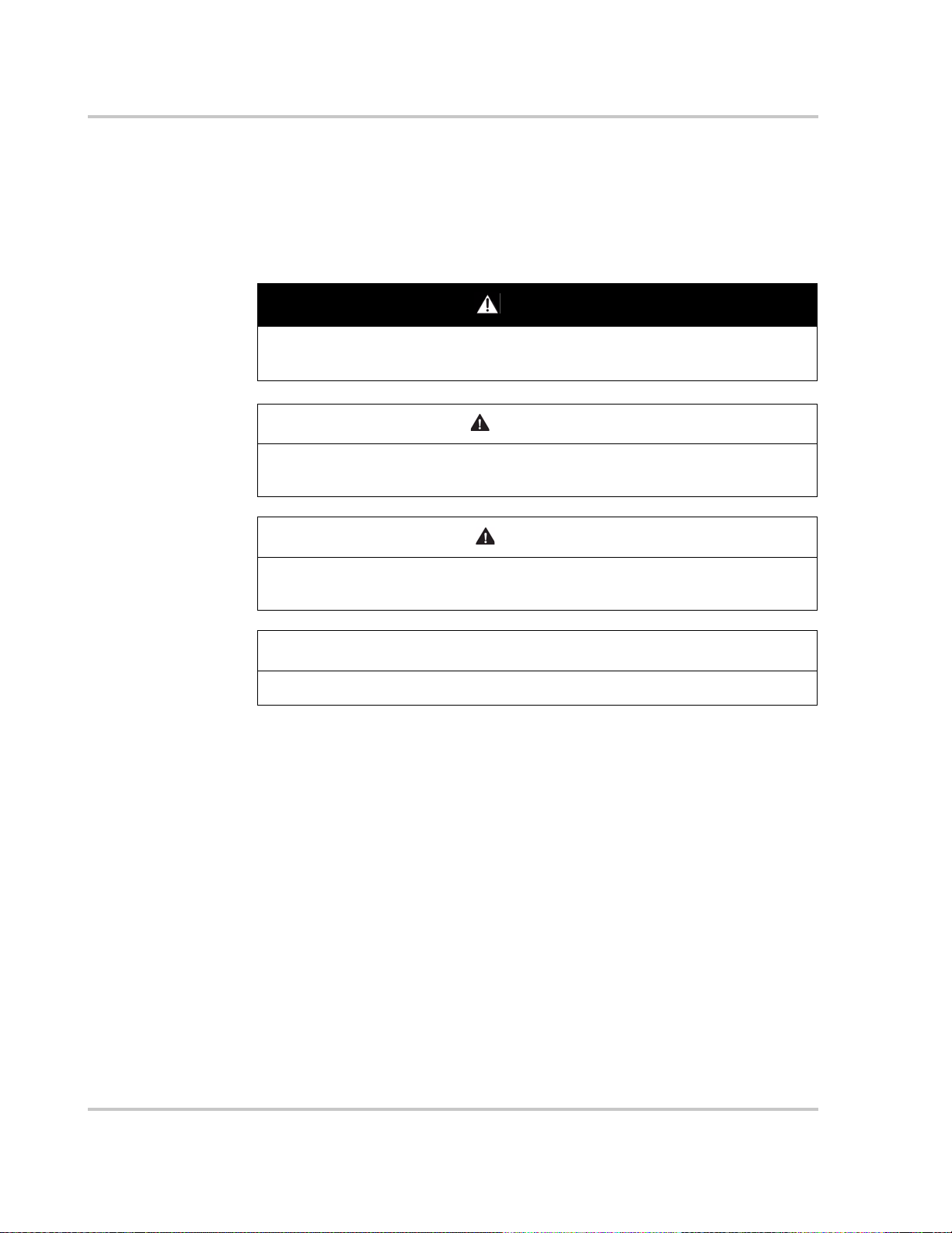
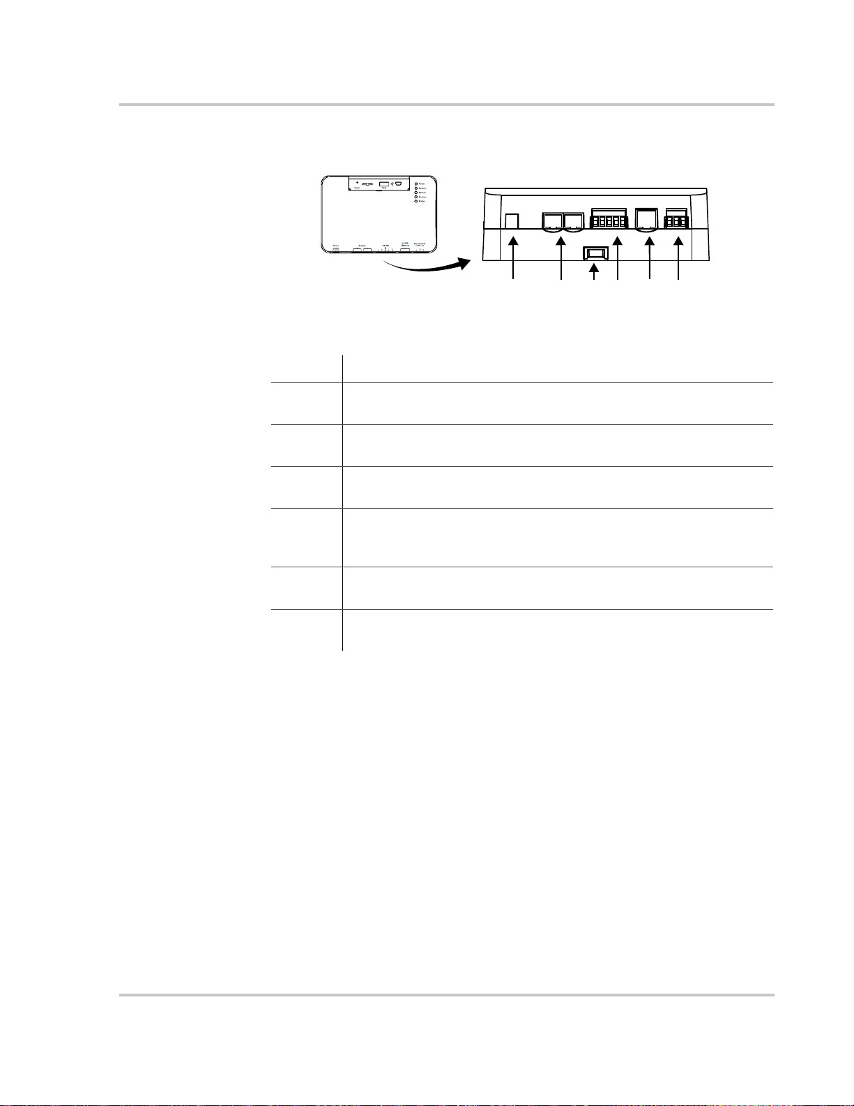
Data Ports and Reset Button
The data ports and reset are located at the top, front of the Conext ComBox.
Their functions are listed in the following table.
Physical Features
Item Description
Reset The Reset pinhole is used to restore factory settings or clear
internal firmware memory. See “Resetting the Conext ComBox to
Factory Settings” on page 3–30 and “Clearing the Internal Firmware
Memory” on page 3–36.
Micro-SD The Micro-SD data port is used with a micro-SD card to extend
Conext ComBox memory for data logging.
Host The Host USB data port is used for uploading firmware upgrades
into the device - a thumb drive or equivalent mass storage device
can be used. See “Clearing the Internal Firmware Memory” on
page 3–36.
Device The Device USB data port is used for transferring files from the
Conext ComBox to a PC.
975-0704-01-01 Revision A 1–3
Overview
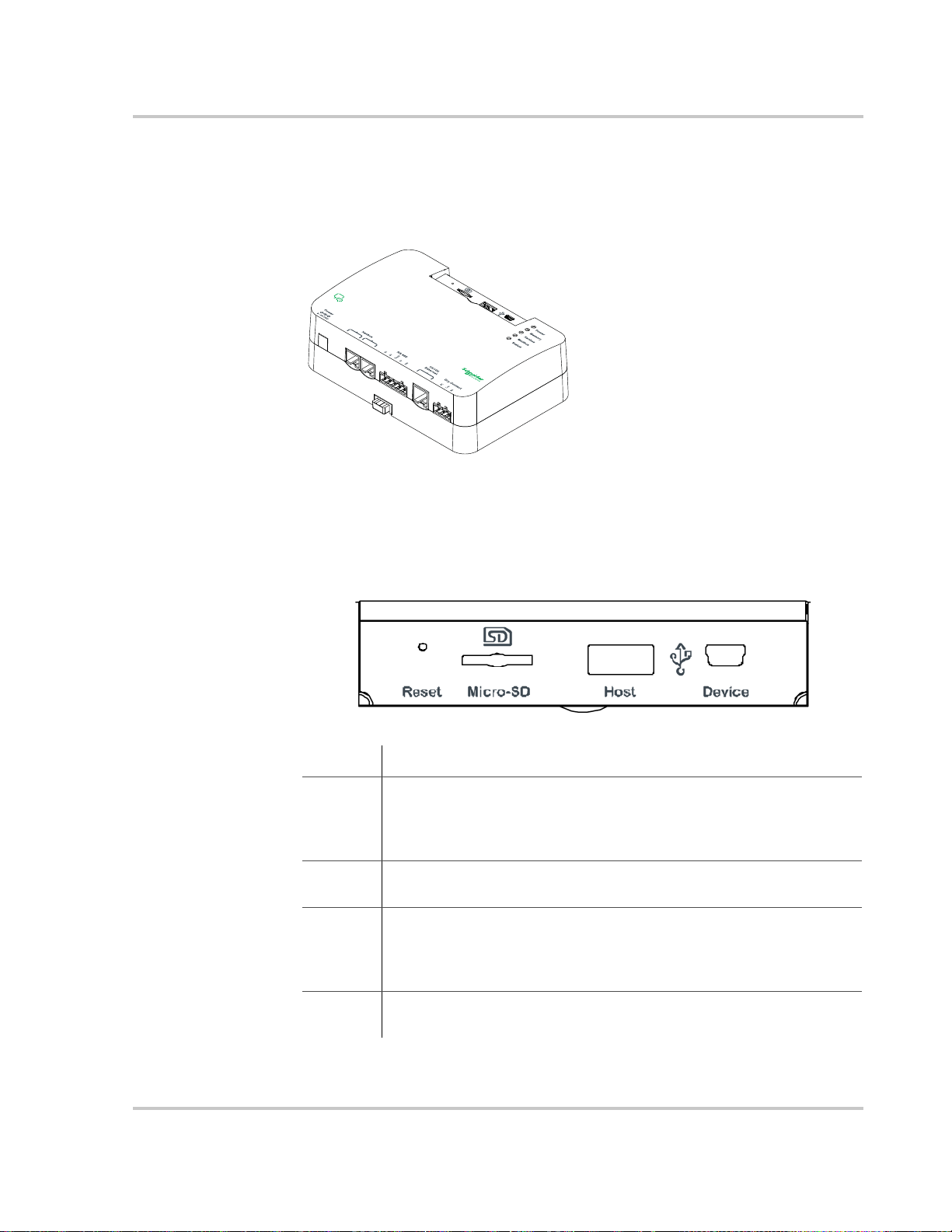
LED Indicator Lights (LEDs)
The Power LED flashes slowly (2 flashes per second) during the Conext ComBox
application loading and flashes quickly during application initialization. The other
LEDs light up one by one as the startup progresses. Once the Conext ComBox is
ready, the power LED is on and other LEDs behave as described below. See
“Monitoring LEDs” for more information.
Item Description
Power Green LED. The Conext ComBox is powered and ready to
communicate when on.
Memory Green LED. Device is logging data to internal memory when
flashing.
Xanbus Green LED. Device is actively communicating or transferring data
with the Xanbus network when on.
Modbus Green LED. Each flash indicates that the Conext ComBox received
a message from the Modbus.
Status Amber LED. Devices on the Conext ComBox system have events or
alerts when on.
1–4 975-0704-01-01 Revision A
Communication and Power Ports
1 23 4 56
Item Description
1 Power port. Use an AC/DC power adapter connected to a wall
outlet to provide power to the Conext ComBox.
2 Xanbus ports. Plug in a CAT5 cable from Xanbus-enabled devices
for communications and/or power to the Conext ComBox.
3 DIN rail sliding catch. Slide up/down to lock/release the Conext
ComBox to a DIN rail.
Physical Features
4 RS 485 Modbus port. Use the RS 485 Modbus connector from a
Modbus device for communications and 24V power terminals to the
Conext ComBox.
5 10/100 Ethernet port for CAT5 cable only. Use to connect to a
DHCP-enabled network router.
6 Dry Contact port. Used for signalling with SELV (Safety Extra Low
Voltage) device.It does not provide power to the Conext ComBox.
See Chapter 2, “Installation” for more information on these ports.
975-0704-01-01 Revision A 1–5
Overview
F
R
E
E
D
O
M
S
W
2
0
0
0
1000
800
600
400
30
100
200
Max Off
LowBattery Battery Type Search BatteryBank
Cutoff Mode Capac ity (Ah)
AGM/
LOW HIGH GELFlooded
Fault kWI nver ting
ACharging
Batt
%
Xanbus Network
Conext ComBox
Local Area Network
Ethernet CablesXanbus Cables
Types of Conext ComBox Networks
The Conext ComBox can interface with different LAN devices using wired or
wireless connections, so you can configure your Xanbus devices and monitor
your power system performance. For this version of Conext ComBox – Freedom
SW, there are two communication network options:
• Conext ComBox on a Local Area Network (LAN)
• Conext ComBox with Remote Access
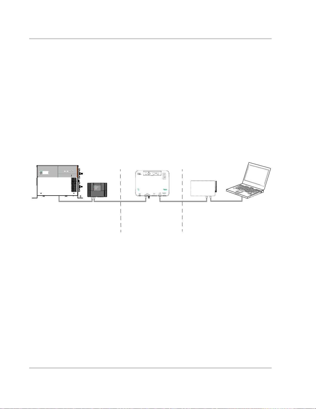
Conext ComBox on a Local Area Network (LAN)
When the Conext ComBox is part of a LAN, you can access the Conext ComBox
web user interface from a computer on the same LAN or through a wireless or
wired LAN connection. For configuring the Conext ComBox, an Ethernet
connection is required between the Conext ComBox and a router and computer.
1–6 975-0704-01-01 Revision A
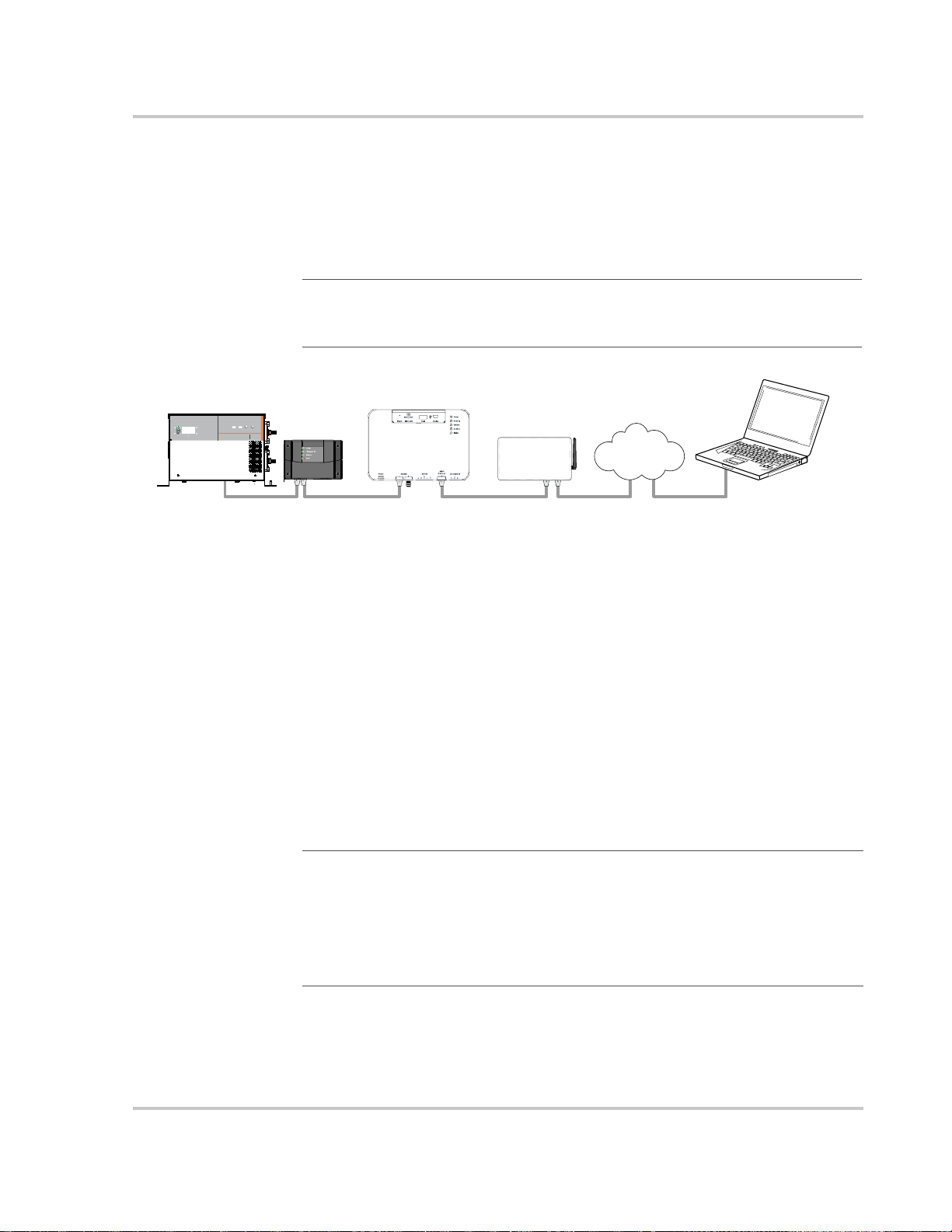
Conext ComBox with Remote Access
F
R
E
E
D
O
M
S
W
2
0
0
0
1000
800
600
400
30
100
200
Max Off
LowBattery BatteryType Sea rch BatteryBank
Cutoff ModeCapa city(Ah)
AGM/
LOW HIGH GELFlooded
Fault kWInver ting
ACharging
Batt
%
Conext ComBox
Ethernet Cables
Internet
Laptop or Tablet
Xanbus cables
Router
You can access the web user interface for the Conext ComBox from a remote
computer using the Internet. The Conext ComBox must be connected to a router.
The router firewall settings must allow port forwarding, which allows the remote
computer to access the Conext ComBox using the router’s IP address and the
port number for the Conext ComBox.
Note
: There is a security risk in port forwarding unencrypted network traffic
over a public network (Internet). It is recommended you use a VPN or a secure
tunnel to route Conext ComBox communication via the Internet.
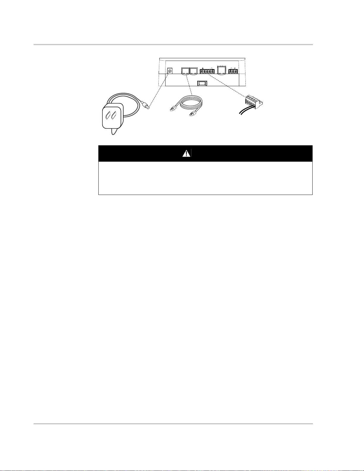
Power Sources for the Conext ComBox
Power Sources for the Conext ComBox
The Conext ComBox consumes an average of 2 W under most operating
conditions and up to 10 W maximum. The power sources connected to the
Conext ComBox must be capable of providing this power requirement.
There are three power sources for the Conext ComBox:
• AC/DC power adapter (supplied)
• Freedom SW inverter/charger via CAT5 or CAT5e cable (Xanbus cable)
• 24 V DC power input connections on the RS 485 Modbus connector
All three sources can be used alone or simultaneously. Typically, the supplied
AC/DC power adapter is used as a primary source with either a Xanbus or a
RS 485 Modbus connection as secondary sources.
Note: Modbus support is available only for the Conext ComBox (Part Number
865-1058), and Conext Modbus Converter (Part Number 865-1059), used with
Schneider Electric Conext series inverter products.
The RS 485 Modbus connector supplied with this Conext ComBox – Freedom
SW (Part Number 809- 0918), is not required for operation or supported by
Xantrex technical support.
975-0704-01-01 Revision A 1–7
Overview
DANGER
AC/DC power
adapter
Xanbus cable
24 V DC input on
RS 485 connector
HAZARD OF ELECTRIC SHOCK AND FIRE
Connect only to Safety Extra Low Voltage (SELV) circuits and power sources.
Failure to follow these instructions will result in death or serious injury.
Safety Extra Low Voltage (SELV) is a designation that refers to a circuit in which
the voltages within the circuit and from the circuit to ground have values that are
not a shock hazard, under both normal and single fault conditions. In the Conext
ComBox, the SELV circuits and their intended connections are:
• Supplied AC/DC power adapter connected to the power port of the Conext
ComBox.
• Xanbus communications and power which come from SELV circuits on Xanbusenabled Schneider products.
• 24 V DC power input connections which must be SELV and are connected to the
Conext ComBox via the RS 485 Modbus connector.
• SELV Ethernet circuits or Class 2 circuits (Class 2 is a 24V, 100VA limited circuit).
• An external SELV circuit connected via the Dry Contact connector (see “Wiring
the Dry Contact Connector” on page 2–8).
1–8 975-0704-01-01 Revision A

User Interface
User Interface
This section describes the elements of the web-based user interface for the
Conext ComBox. This interface is used to check the status of the Conext
ComBox, configure, monitor and log data for your network, and perform
upgrades. The menu bar contains icons for all functions plus home, close and
setup icons.
To access the web user interface, log in with a user name and password. For
more details see “Logging In” on page 3–3.
Web browsers Correct operation of the web interface has been verified with the following
browsers:
• Mozilla Firefox 12.x or later
• Microsoft Windows Internet Explorer 8.x or later*
• Google Chrome 18.x or later
• Safari 5.x or later
• Android 4.0 or later (Ice Cream Sandwich)
Other browsers have not been tested and may have varying degrees of
compatibility with the Conext ComBox.
*Internet Explorer 8.0 and 9.0 do not support firmware upgrade.
Note
: JavaScript and cookies must be enabled in your Web browser for the
interface to function.
975-0704-01-01 Revision A 1–9
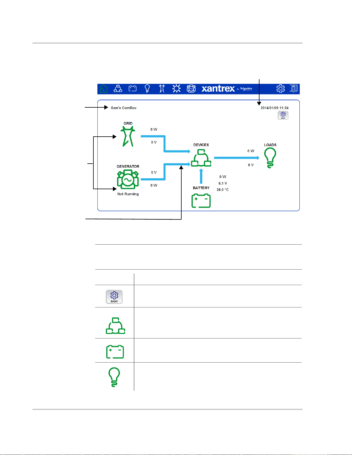
Overview
Name assigned to the
ComBox. See
page 3–16.
Current date and time.
See page page 3–7
Indicates the
direction of energy
flow
The Freedom SW has
one AC input. Your
ComBox will be
configured to display
GRID or GENERATOR
power flow (but not
both at the same
time).
Home Screen
1–10 975-0704-01-01 Revision A
Note: Although the Conext ComBox interface is displayed in a web browser, it
does not use the Back button to display previous screens. All navigation
through the interface is done within the Home screen.
Item Description
Displays basic settings for configuring the Conext ComBox for
use with the Freedom SW inverter/charger and Xanbus AGS.
Displays all power system devices connected to the ComBox. A
yellow flashing device icon indicates a warning. A red flashing
icon indicates a fault. Click a device icon to view a system
status summary.
Shows battery status such as voltage, current, power,
temperature, charge cycle information and historical
information.
Shows the load status for the system and devices including
power, apparent power, voltage, current, and frequency.
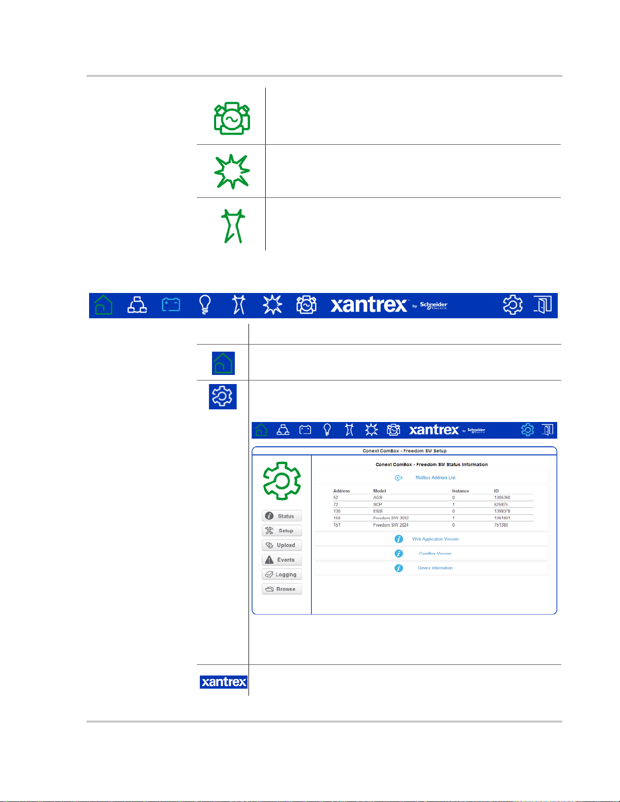
Menu Bar
User Interface
Shows the status of generator input energy
This feature is reserved for future use. A Xanbus-enabled solar
charge controller certified for use on a vehicle or boat is not
currently available.
Shows the status of AC shore power from the main utility grid.
Item Description
Returns you to the Home menu.
Displays the Conext ComBox Status Information screen. Click the
Setup button in the left side menu to open the Conext ComBox
Setup screen.
In the Conext ComBox Setup screen, you can configure ComBox
settings such as Time Zone and Network Settings. For more
information, see “Conext ComBox Setup Buttons”.
Links to xantrex.com.
975-0704-01-01 Revision A 1–11
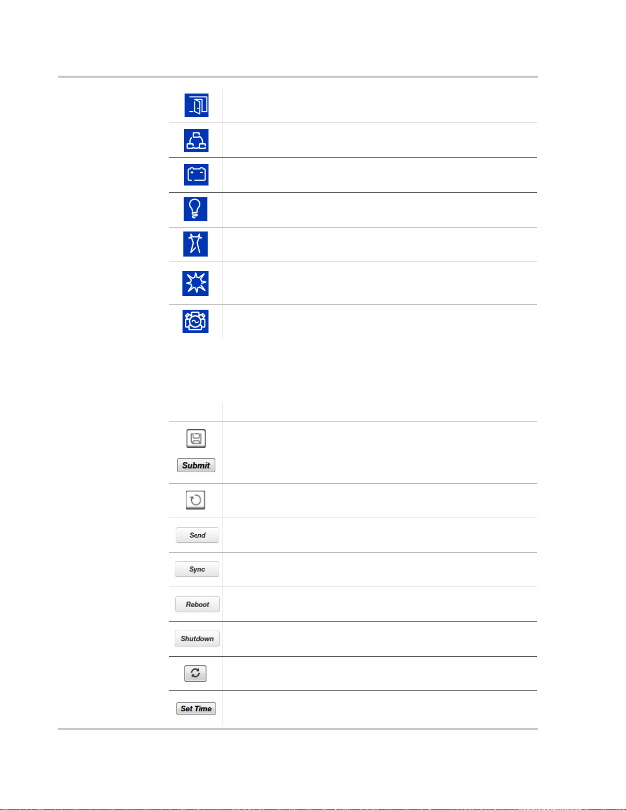
Overview
Closes the Conext ComBox web user interface and logs out.
Shows Xanbus Devices of all types in the network.
Shows the battery status for the network.
Shows system AC output power, voltage and current (loads).
Shows the status of AC shore power from the public utility grid.
This feature is reserved for future use. A Xanbus enabled solar
charge controller certified for use on a vehicle or boat is not
currently available.
Displays the status of generator input energy.
Conext ComBox Setup Buttons
These buttons are found in the Conext ComBox Setup screen.
Item Description
Saves a parameter’s new value to the Conext ComBox.
Recalls (or refreshes) a parameter’s previous value that is still not
saved (or that may have been changed by another device).
Found in E-mail-related settings, the Conext ComBox sends
information out via the e-mail system.
Found only in the Network Time (SNTP) setting, this button performs
a manual network time synchronization.
Found only in General Settings, this button reboots the Conext
ComBox.
Found only in General Settings, this button shuts down the Conext
ComBox.
Captures the most up-to-date value from a parameter.
Sets the time and date in the Conext ComBox.
1–12 975-0704-01-01 Revision A
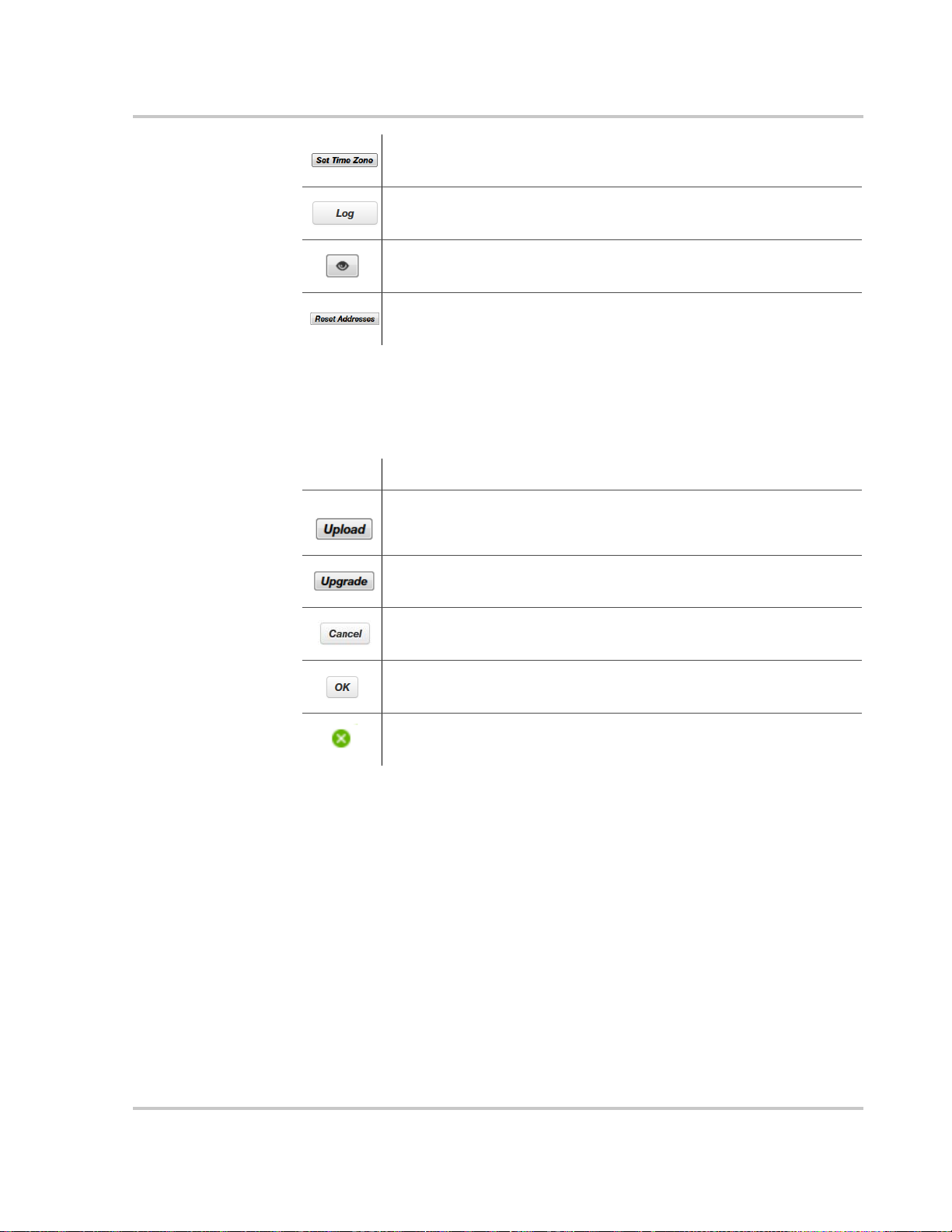
Other Buttons
These buttons are found in other Conext ComBox web user interface screens, such as
Upload screens and dialog screens.
System Scheduled Maintenance
Sets the time zone in the Conext ComBox.
Found only in FTP Logger Settings, this button sends a sample log
file to an FTP site.
Causes a physical indicator on the Xanbus device to flash, light up,
or beep, depending on the device.
Found only in Modbus Address List Settings, this button resets the
Modbus addresses of Xanbus devices.
Item Description
Found in Firmware Uploads And Device Upgrades, this button
uploads an upgrade file from a storage device to the Conext
ComBox.
Found in Firmware Uploads And Device Upgrades, this button
initiates the device upgrade process for a Xanbus device.
When visible this provides the option to cancel a prompted action.
Enacts an action prompted by a dialog screen.
Closes a user interface screen or a pop-up application.
System Scheduled Maintenance
The Conext ComBox is unavailable for approximately three minutes at 3:05 AM daily.
During this time, the Conext ComBox performs routine maintenance and does not
respond to queries via any of its external interfaces, such as Modbus TCP, RS 485, Web
Services, and Web Pages. Data logging is also suspended during this period.
975-0704-01-01 Revision A 1–13

Overview
1–14 975-0704-01-01 Revision A

2 Installation
Chapter 2 describes how to install, wire, and
connect the Conext ComBox – Freedom SW to
your network.
It includes:
• Choosing a Location
• Materials and Tools Required
• Mounting the Conext ComBox
• Wiring the RS 485 Modbus Connector for
Data Communication
• Wiring the Dry Contact Connector
• Wiring the Conext ComBox to an Ethernet
Network
• Turning On the Conext ComBox
• Connecting to the Web Interface Using the
Discovery Tool
• Connecting to the Web Interface Using a
USB Thumb Drive
• Connecting to the Web Interface Using an
Android Tablet
975-0704-01-01 Revision A 2–1

Installation
DANGER
Choosing a Location
Choose a clean, dry, easily accessible location indoors.
If you mount the Conext ComBox on a wall, the recommended height is at eyelevel so that you can clearly see the LEDs and have easy access to the data
ports.
All the communication ports on the Conext ComBox are accessible from the
bottom of the device when mounted on a wall or DIN rail. Clearance of at least 2
inches (50 mm) below the device is needed to allow for the bending radius of
cables that connect to the Conext ComBox.
You should not run cables through conduits that can be exposed to lightning
strikes.
The following are recommended maximum cable lengths in a Conext ComBox
system:
• 131 feet (40 m) Total Xanbus network
• 328 feet (100 m) Router to Conext ComBox
• 164 feet (50 m) Modbus Master (RS 485) to Conext ComBox
HAZARD OF ELECTRIC SHOCK AND FIRE
• Connect only to Safety Extra Low Voltage (SELV) circuits and power
sources.
• All wiring must be done by qualified personnel to ensure compliance with
all applicable installation codes and regulations.
• Do not expose the Conext ComBox – Freedom SW to rain, snow, spray, or
bilge water.
• Do not disassemble. No user serviceable parts inside.
• Do not install and/or operate in compartments containing flammable
materials or in locations that require ignition-protected equipment.
Failure to follow these instructions will result in death or serious injury.
2–2 975-0704-01-01 Revision A

Materials and Tools Required
Materials List
The following materials are supplied in the Conext ComBox package:
p Conext ComBox unit
p Conext ComBox Quick Start Guide
p AC/DC power adapter (PN: 0J-921-0023-Z) with replaceable multi-plug for
North America, Europe, Asia, UK
• 5.5 mm diameter (outer, negative), 2.1 mm diameter (inner, positive)
connector
• 12 VDC (output), 1.5 ADC
p Dry contact connector
p RS 485 Modbus connector
p Ethernet cable (2 m)
p USB cable (1.8 m)
p Xanbus network terminator
p Mounting hardware
Materials and Tools Required
Additional Material and Tools
The following materials and tools are not supplied but are required to complete
the installation:
• CAT5 or CAT5e network cable(s) for Xanbus connections - 6.5 feet (2 m) or
longer
• Modbus network cable(s)
• Wire stripper
•Ferrules
For wall mount:
• Two #6 (or equivalent) mounting screws for non-drywall mounting
• Screwdriver set
For DIN rail mount:
• 35-mm “top hat” DIN rail (EN50022)
• Pliers
• Diagonal cutter or heavy duty scissors
975-0704-01-01 Revision A 2–3
Installation
¼ inch
(6 mm)
Mounting the Conext ComBox
Wall Mount
To mount the Conext ComBox on a wall:
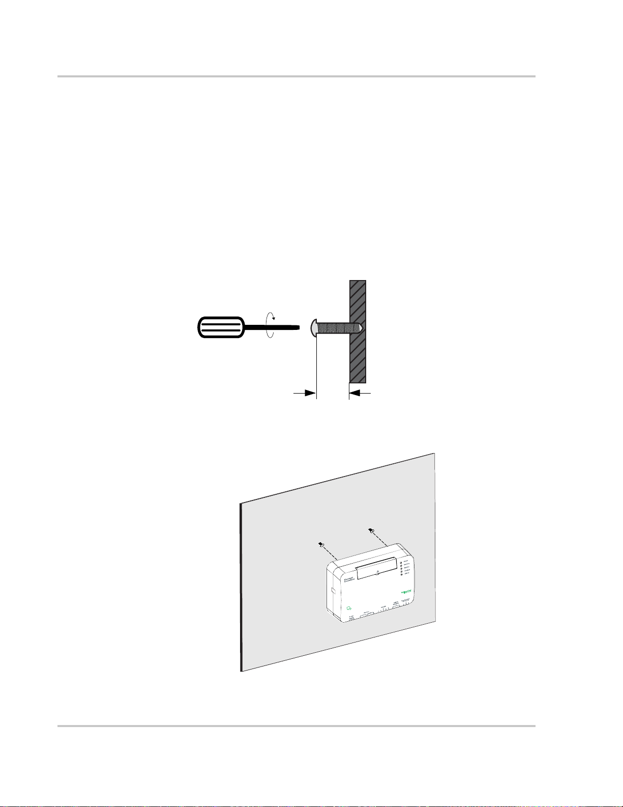
1. Choose the location for mounting the device. Mounting hardware for plywood
wall material is supplied.
2. Using the template in the Conext ComBox Quick Start Guide, mark the
mounting holes on the wall with a pencil. The holes must be at the same
height and 4 7/16 inches (112 mm) apart.
3. Insert the mounting screws supplied in the marked locations on the wall,
leaving a space of about ¼ inch (6 mm) between the wall and screw head.
.
4. Place the Conext ComBox on the mounting screws, and confirm a snug fit
before going to the next step.
5. Connect the wiring and cables. Go to “Wiring the Conext ComBox to an
Ethernet Network” on page 2–9.
2–4 975-0704-01-01 Revision A

DIN Rail Mount
Side tab
DIN rail catch
Mounting the Conext ComBox
A standard 35-mm “top hat” DIN rail (EN50022) must be used for mounting.
To mount the Conext ComBox on the DIN Rail:
1. Choose the location for mounting the device.
2. Using heavy duty scissors or a diagonal cutter, cut both ends of the side tab
on one end of the Conext ComBox.
3. Break off the side tab. You may need to use pliers for this.
4. Repeat steps 2 and 3 for the tab at the other end of the Conext ComBox.
5. Use a suitable tool, such as a screwdriver, to pull down the catch on the
bottom of the Conext ComBox.
6. Mount the Conext ComBox on the DIN rail and release the catch. See the
following illustration.
7. Connect the wiring and cables.
975-0704-01-01 Revision A 2–5
Installation
S
hi
el
d
D
0D1
3/8 in.
(10 mm)
Wiring the RS 485 Modbus Connector for Data
Communication
Note
: Modbus support is available only for the Conext ComBox (Part Number
865-1058), and Conext Modbus Converter (Part Number 865-1059), used with
Schneider Electric Conext series inverter products.
The RS 485 Modbus connector supplied with this Conext ComBox – Freedom
SW (Part Number 809-0918), is not required for operation or supported by
Xantrex technical support.
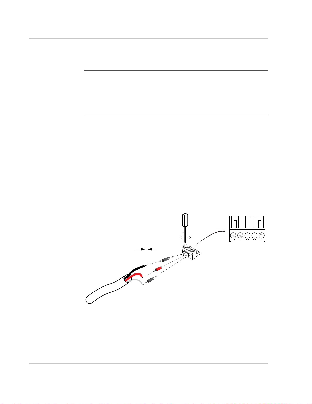
The RS 485 Modbus connector provides three terminals to wire communication
cables to the Conext ComBox. The five-terminal RS 485 connector uses the first
three terminals for a data cable. The cable has a size of 16–24 AWG with
1.5 mm
To wire the RS 485 Modbus connector for data communication:
1. Select a two-wire, twisted pair, shielded cable not longer than 164 feet
2. Strip 3/8 in.(10 mm) from the end of the wires to be connected and attach
3. Insert the ferrules and the shield wire into the connector terminals as shown
2
–0.25 mm2 wires. The cable can be shielded or non-shielded.
(50 m). Refer to the local electrical code and application to select the
insulation and temperature class of the cable to be used.
ferrules to the two signal wires (red and black in the following diagram).
in the following diagram.
4. Secure the wires by tightening the screw on the terminal.
The middle terminal is not connected internally but is provided for the shield
connection of the cable.
5. If you intend to use the Dry Contact, go to “Wiring the Dry Contact
2–6 975-0704-01-01 Revision A
Connector”. Otherwise, go to “Wiring the Conext ComBox to an Ethernet
Network”.
Wiring the RS 485 Modbus Connector for Data Communication
24 V
Power
Supply
See NOTE below.
Modbus
Device 1
RS 485
120-ohm
Terminator
Modbus
Device 2
Modbus
Device 3
Modbus
Device 4
RS 485
120-ohm
Terminator
Connect the
RS 485 connector
to the RS 485 port.
D1
D0
Shield
Modbus versus
Xanbus
Connecting the
Conext ComBox
with other Modbus
Devices
The RS 485 Modbus connection and Xanbus cable connection provide data
communication from the network and devices to the Conext ComBox.
Communication with Modbus devices is handled through the RS 485 or 10/100
Ethernet connection on the Conext ComBox while communication with Xanbus
components occurs through the Xanbus ports of Xanbus-enabled devices.
In the Modbus implementation, the Conext ComBox acts as a slave to an RS 485
master device. The RS 485 connection to the Conext ComBox allows
communication between the Xanbus network and the master device. This
enables Conext devices to link to third-party software and building management
systems.
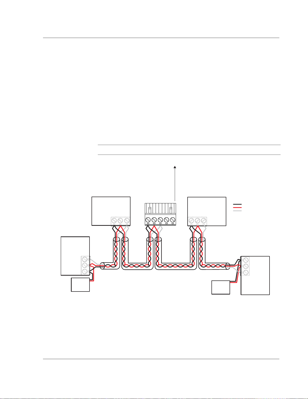
If a Modbus device, including the Conext ComBox, is installed as the last device
in a daisy chain, a 120 ohm terminator must be used because they do not have
an internal terminator for the RS 485 network. When inserting two wires in one
terminal, as in the case of daisy-chained RS 485 Modbus devices, use smaller
gauge wires. See the following example.
Note
: Turn off all Modbus and other devices prior to wiring the connectors.
975-0704-01-01 Revision A 2–7
Installation
DANGER
NO
Com
NC
normally
closed
common
normally open
3/8 in.
(10 mm)
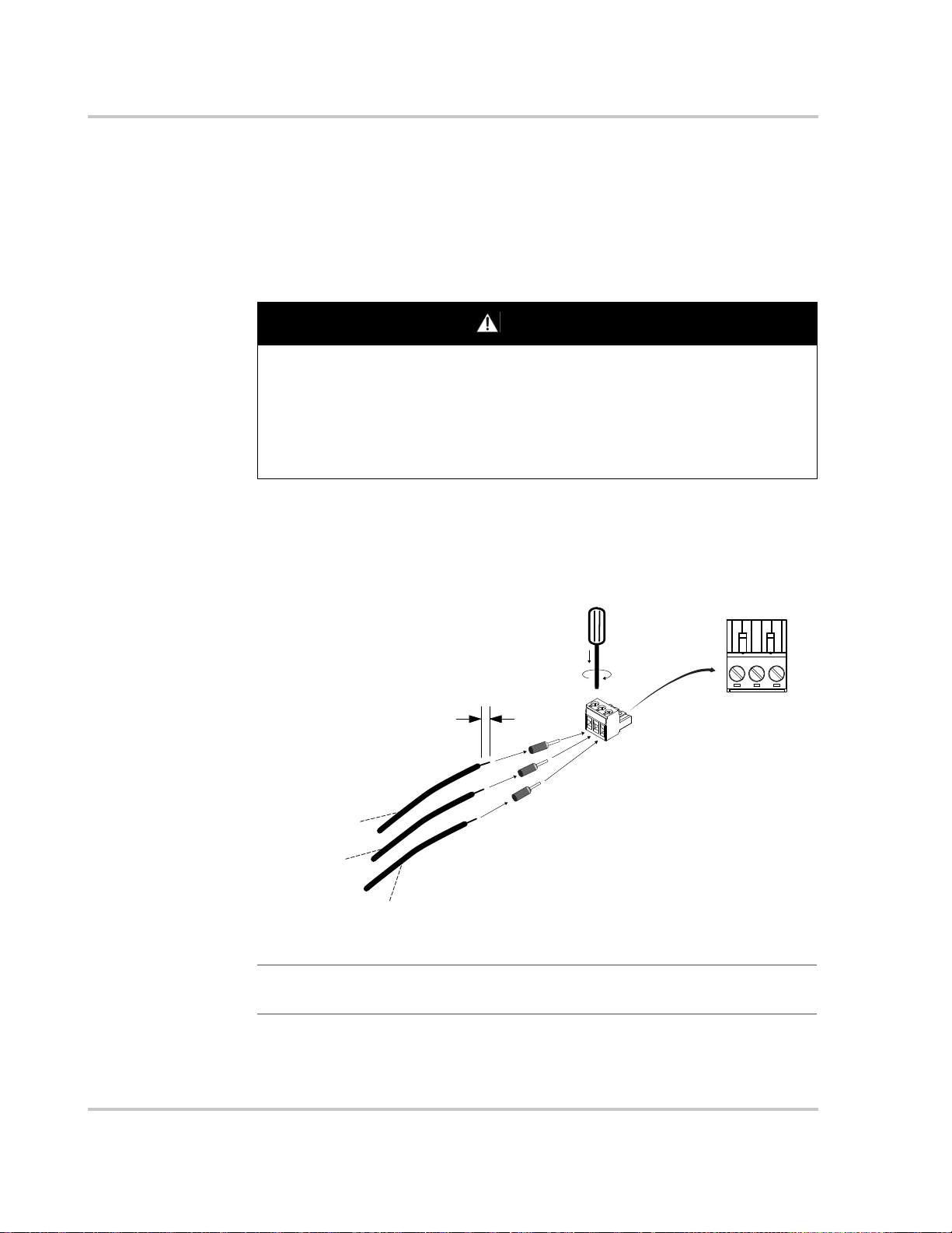
Wiring the Dry Contact Connector
Wiring instructions for dry contact wiring for SELV devices is included in this
section. The dry contact connector is intended to control the trigger of SELV
devices such as small DC fans or external AC or DC relays. It does not provide
power to the Conext ComBox.
To wire the dry contact connector:
ELECTRIC SHOCK AND FIRE HAZARD
• Turn off all other devices prior to wiring the connectors.
• The Dry contact port must only be connected to a circuit rated 24V DC
max, 4A max, and supplied from an SELV source.
Failure to follow these instructions will result in death or serious injury.
1. Strip 3/8 in. (10 mm) from the end of the wire to be connected and attach
ferrules to the bare wires.
2. Insert the ferrule into the Dry Contact connector’s wire terminal.
3. Secure the wire by tightening the screw on the terminal.
4. Repeat steps 2 and 3 for the remaining wires.
Note: The Dry Contact Connector should not be used for any safety-critical
applications.
2–8 975-0704-01-01 Revision A
5. Once all the Dry Contact wires are secured, push the Dry Contact connector
into the Dry Contact port until it locks into place.
6. Go to “Wiring the Conext ComBox to an Ethernet Network”.

Wiring the Conext ComBox to an Ethernet Network
NOTICE
Wiring the Conext ComBox to an Ethernet Network
Note
: The computer and network router may remain powered at this stage in
the process. If not already powered, make sure these two devices are on before
proceeding.
Before connecting a computer and router to the Conext ComBox, make sure it
meets the following prerequisites.
Router The network router must be able to supply DHCP addresses automatically to
connected devices. If your network router does not support automatic DHCP,
refer to your network router’s user guide or contact your system administrator.
Operating System •Microsoft
•Microsoft
• Windows Vista
•Mac OS
Web Browsers • Mozilla
•Microsoft
• Google Chrome
• Safari
• Android 4.0 or later (Ice Cream Sandwich)
®
Windows® 7 (recommended) or later
®
Windows XP® (SP2, SP3)
®
X86
®
X 10.4.8. or later
®
Firefox® 12.x or later
®
Windows® Internet Explorer® 8.x or later
™
18.x or later
®
5.x or later
Note: JavaScript and cookies must be enabled in your web browser.
To connect the Conext ComBox to a computer on an Ethernet network:
1. Make sure the computer and network router are turned on and the Conext
ComBox is not turned on. Make sure the network router selected has DHCP
enabled.
2. Connect one end of an Ethernet cable to the computer’s network port.
EQUIPMENT DAMAGE
• Do not connect an Ethernet cable from the Conext ComBox to the
WAN/MODEM port on the network router.
• Do not connect an Ethernet cable plug into a Xanbus port on the Conext
ComBox.
Failure to follow these instructions can damage equipment.
3. Connect the other end of the Ethernet cable to a vacant Ethernet/LAN port on
the network router.
975-0704-01-01 Revision A 2–9

Installation
Step 1:
Conext ComBox OFF
Laptop, tablet, and router ON
Step 2
Step 3
Ethernet cable
supplied
Step 4
Step 5
4. Connect one end of the Ethernet cable (supplied) to the LAN port on the
5. Connect the other end of the Ethernet cable to the Conext ComBox.
network router.
At this stage, the network router should be on but the LED showing port
activity on the router will not show any indication.
At this stage the Ethernet cable should be the only cable (except for the Dry
Contact if used) plugged into the Conext ComBox.
2–10 975-0704-01-01 Revision A

Turning On the Conext ComBox
WARNING
The Conext ComBox must be wired into an Ethernet connection before it is
powered up. Follow the sequence of steps in “Wiring the Conext ComBox to an
Ethernet Network” on page 2–9.
To turn on the Conext ComBox:
1. Connect a power source to the Conext ComBox. You can do either of the
following:
• Plug the AC/DC power adapter into the AC wall outlet (see “Connecting
the AC/DC Power Adapter”), or
• Plug the RS 485 connector, which has been wired with a 24 V DC power
supply, to the RS 485 port on the Conext ComBox until it locks into place.
See “Wiring the RS 485 Modbus Connector for Power to the Conext
ComBox” for the wiring procedure.
Note
: Modbus support is available only for the Conext ComBox (Part Number
865-1058), and Conext Modbus Converter (Part Number 865-1059), used with
Schneider Electric Conext series inverter products.
The RS 485 Modbus connector supplied with this Conext ComBox – Freedom
SW (Part Number 809- 0918), is not required for operation or supported by
Xantrex technical support.
Turning On the Conext ComBox
PHYSICAL INJURY HAZARD
Xanbus is a valid power source for the Conext ComBox. However, for the initial
configuration, using Xanbus as a power source is not recommended. The
Conext ComBox clock will override the other Xanbus devices’ clocks and
could trigger unintentional time-based events. Therefore, DO NOT connect the
Conext ComBox to the Xanbus network prior to setting up the internal clock of
the Conext ComBox. Refer to “Changing the Time” on page 3–7. If Xanbus is
the only source powering the ComBox, after installation verify the time settings
in all devices.
Failure to follow these instructions can result in death or serious injury.
2. When power is applied to the Conext ComBox, all the LEDs flash once and
then the Power LED flashes intermittently for approximately two minutes
during the application loading and initialization sequence.
Wait until the Power LED lights up steadily before proceeding to the next
step. See “LED Indicator Lights (LEDs)” on page 1–4.
3. When the Conext ComBox is ready, proceed to either “Connecting to the
Web Interface Using the Discovery Tool” on page 2–15 or “Connecting to the
Web Interface Using a USB Thumb Drive” on page 2–16.
975-0704-01-01 Revision A 2–11

Installation
DANGER
Connecting the AC/DC Power Adapter
ELECTRIC SHOCK AND FIRE HAZARD
Use only the AC/DC Power Adapter supplied with this Conext ComBox unit.
When ordering a replacement, reference PN: 0J-921-0023-Z.
Failure to follow these instructions will result in death or serious injury.
To use the AC/DC power adapter supplied with the Conext ComBox as a
power source:
1. Conext ComBox uses a universal plug with interchangeable pins and plug
styles.
2. Connect the power plug to the AC outlet.
3. Connect the other plug of AC/DC power adapter to the Power port on the
Conext ComBox.
4. Go to step 2 of “Turning On the Conext ComBox”.
Wiring the RS 485 Modbus Connector for Power to the Conext ComBox
Note: Modbus support is available only for the Conext ComBox (Part Number
865-1058), and Conext Modbus Converter (Part Number 865-1059), used with
Schneider Electric Conext series inverter products.
The RS 485 Modbus connector supplied with this Conext ComBox – Freedom
SW (Part Number 809- 0918), is not required for operation or supported by
Xantrex technical support.
To use the Modbus RS 485 connector to provide power to the Conext ComBox,
use the following procedure. When powering the Conext ComBox through the
24 V DC terminals on the RS 485 connector, use a power supply (AC/DC or DC/
DC) that provides galvanic isolation to meet the required SELV connections.
2–12 975-0704-01-01 Revision A
DANGER
ELECTRIC SHOCK AND FIRE HAZARD
NOTICE
If the power terminals on the Modbus RS 485 connector are used, the RS 485
connector must only be connected to a circuit rated 24V DC max, 1A max
(fused on the positive wire), and supplied from an SELV source.
Failure to follow these instructions will result in death or serious injury.
EQUIPMENT DAMAGE
Turn OFF all devices before connecting cables. The Conext ComBox does not
have an ON/OFF switch. See “Power Cycle” below.
Failure to follow these instructions can damage equipment or affect
performance.
Power Cycle To power cycle the Conext ComBox:
1. Turn the Conext ComBox OFF – perform a proper shutdown (see “Shutting
down the Conext ComBox” on page 3–17) then unplug and disconnect it
from all power sources.
2. Wait ten seconds before the next step.
Ensure that there is no USB thumb drive inserted in the USB Host port.
Turning On the Conext ComBox
3. Turn the Conext ComBox ON – plug and connect it to a power source.
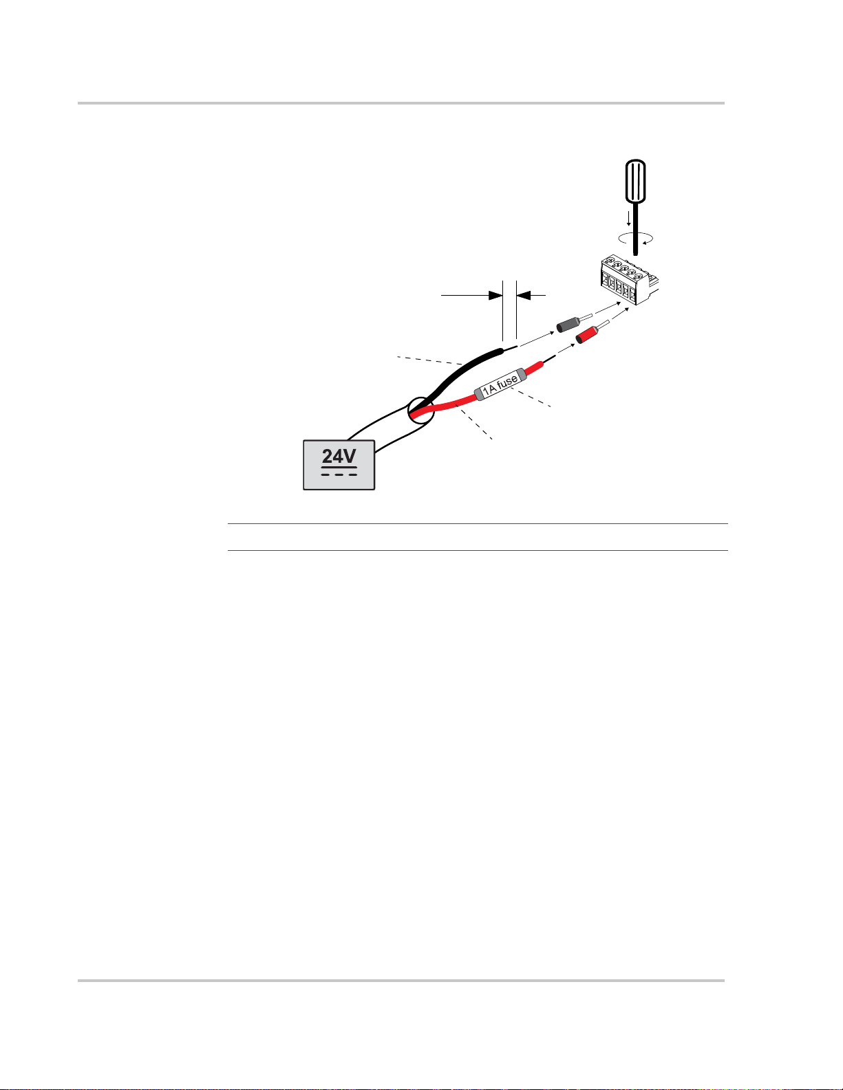
Wiring Steps To wire the RS 485 Modbus connector for power to the Conext ComBox:
1. Turn off the 24 V DC power supply.
2. Unplug the RS 485 connector from the RS 485 port on the Conext ComBox.
3. Strip 3/8 in. (10 mm) from the end of the 0 V (–) wire of the power cable.
4. Terminate the wire with a ferrule.
5. Install a 1A DC fuse on the 24 V (+) wire of the power cable and strip 3/8 in.
(10 mm) from the end of the wire.
6. Terminate the wire with a ferrule.
975-0704-01-01 Revision A 2–13
Installation
3/8 in.
(10 mm)
power supply
24 V (+)
0 V (–)
1A DC fuse on
the positive wire
7. Insert the ferrules into the Modbus connector’s wire terminals as shown.
Note
: The polarity of the wires is shown above and on the unit.
8. Secure the wires by tightening the screws on the terminal.
9. Plug the Modbus connector into the RS 485 port of the Conext ComBox.
10. Turn on the 24 V DC power supply.
11. Go to step 2 of “Turning On the Conext ComBox”.
2–14 975-0704-01-01 Revision A
Connecting to the Web Interface Using the Discovery Tool
Connecting to the Web Interface Using the Discovery Tool
After the Conext ComBox is wired into and powered up on a LAN, it will exist as a
LAN device at an IP address. The following procedure describes how to find the
Conext ComBox LAN address using the Discovery Tool.
To find the Conext ComBox on your network:
1. Download the Discovery Tool from the website:
http://xantrex.com/power-products/default/conext-combox-freedomsw
2. Temporarily disable all antivirus software including firewall protection
software running in the background.
3. Open the Device Discovery Tool folder.
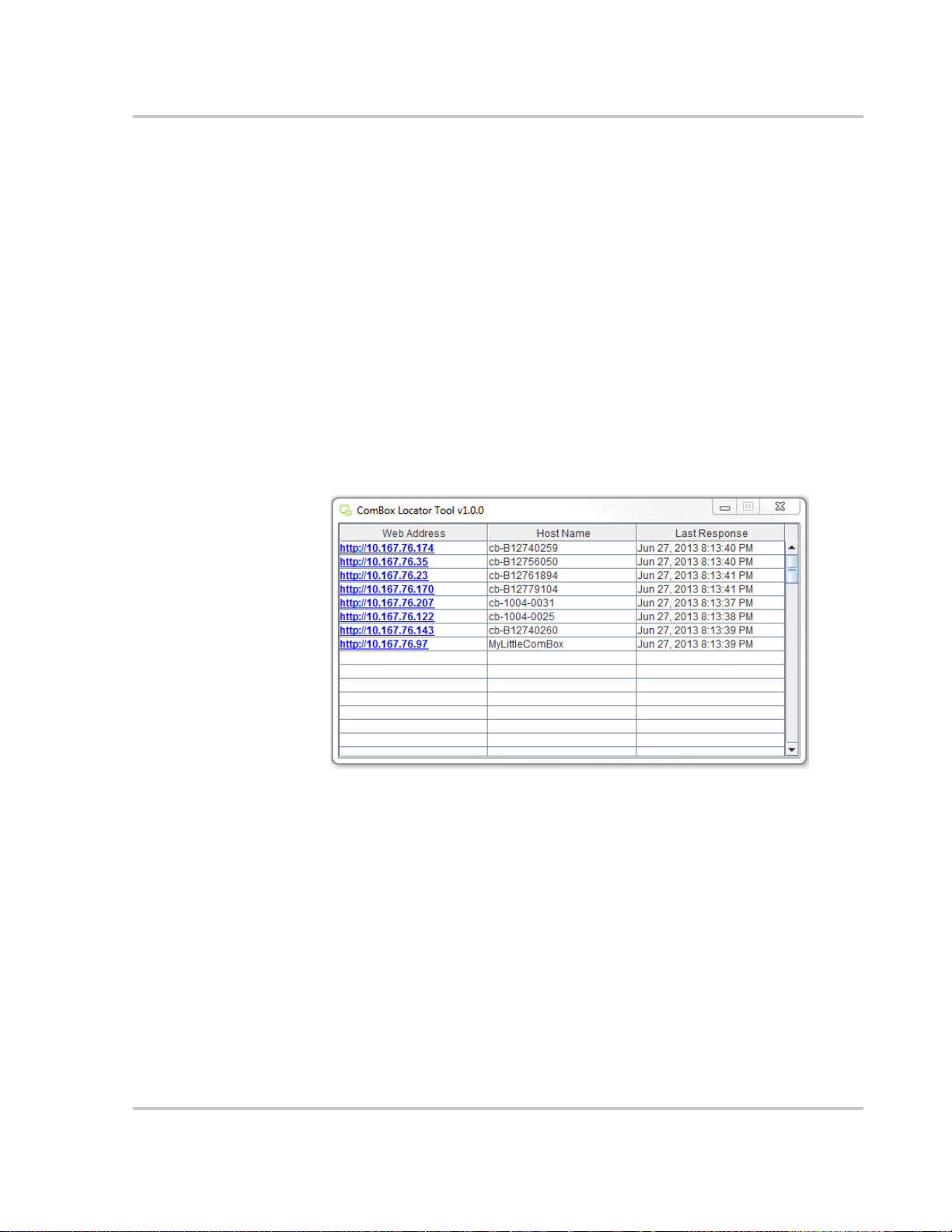
4. Double-click ConextComBoxLocator.jar.
This tool requires Java Runtime Environment (JRE). If you see a message
about this, go to http://www.java.com/en/download/index.jsp to download and
install JRE.
5. In the list that appears, click the Web Address for the Conext ComBox
(cb-XXXX where XXXX is a factory- assigned number).
If a web browser opens up, you will see the Conext ComBox user interface
Login window. Go to the next step.
The default value of the Web Server Port is 80. For example, if you change
this value to 8080, you must append the URL address with “:8080” at the end
of the IP address (e.g. http://10.167.73.66:8080).
If a web browser window does not open:
• Note the Web Address for the Conext ComBox.
• Open a web browser.
• Enter the Conext ComBox Web Address in the URL field.
• Press Enter on the keyboard. The Conext ComBox web interface Login
window appears.
975-0704-01-01 Revision A 2–15

Installation
6. Enable all antivirus software including firewall protection software.
7. To complete configuration of your Conext ComBox, go to the “Configuration”
section.
Connecting to the Web Interface Using a USB Thumb Drive
In cases where it is not practical to obtain the Conext ComBox’s IP address using
the Device Discovery tool (or using the Windows network browser), obtain the IP
address using a USB thumb drive.
To connect using a USB thumb drive:
1. Plug a USB thumb drive into the Conext ComBox’s USB Host data port while
the Conext ComBox unit is powered on (the Power LED is steadily on and not
flashing).
2. Watch the Memory LED and wait for it to flash quickly five times.
3. Remove the USB thumb drive from the USB Host data port.
4. Plug the USB thumb drive into your computer’s USB port.
5. Use the file system browser on your computer to navigate to the thumb
drive’s root directory.
6. Look for a file named serial number.html, where serial number is the Serial
Number of the Conext ComBox.
7. Double-click the serial number.html file. Your default web browser will launch
and display the System Information screen.
2–16 975-0704-01-01 Revision A
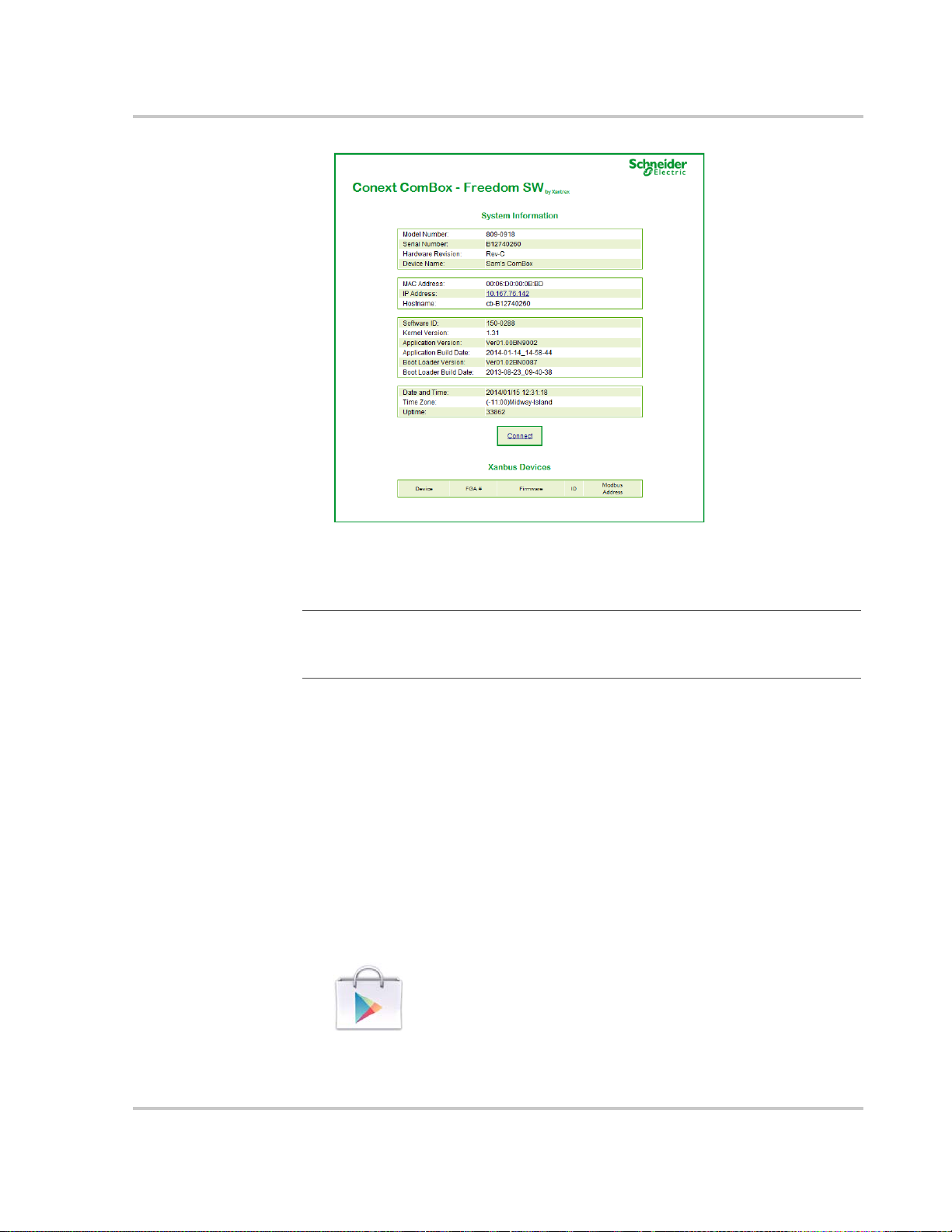
Connecting to the Web Interface Using an Android Tablet
8. Click the Connect button. The web browser opens and the Conext ComBox
web interface Login window appears.
Note: Connecting to the web interface through the System Information screen
only works if your computer is on the same Local Area Network as the Conext
ComBox.
Connecting to the Web Interface Using an Android Tablet
If you want to use a tablet to access the web interface, you must install the
Conext ComBox – Freedom SW mobile application available on Google Play.
The Conext ComBox mobile application is designed for tablets running Android
4.0 or later.
To connect using a tablet:
1. Make sure that the Conext ComBox is turned on and that the router is
connected to the internet with WiFi turned on.
2. On the tablet home screen, tap the Google Play icon:
3. In the Google Play store, search for Conext ComBox Freedom SW.
4. Tap Install and follow the instructions on the screen to install the application.
975-0704-01-01 Revision A 2–17

Installation
2–18 975-0704-01-01 Revision A

3 Configuration
Chapter 3 describes how to configure settings
for the Conext ComBox – Freedom SW. It also
includes how to connect devices to the Xanbus
network.
It includes:
• Configuration Steps
• Logging In
• Changing the Admin Password
• Changing the Time
• Changing E-Mail Settings
• Connecting the Conext ComBox to the
Xanbus Network
• Changing Basic Conext ComBox Settings
• Changing Advanced Conext ComBox
Settings
• Resetting the Conext ComBox to Factory
Settings
• Changing Device Settings
• Upgrading Firmware
975-0704-01-01 Revision A 3–1

Configuration
Configuration Steps
To complete Conext ComBox setup, you must successfully complete the
procedures in Chapter 2, “Installation”. Make sure the Conext ComBox is
connected, the Power LED is on, and the Status LED is off. Your Xanbus devices
should still be in standby mode.
When you log in to the web interface, most of the setup information appears
automatically with their default values. Some information requires change (such
as passwords), some information can be modified as needed, and some
information can only be modified by a qualified IT professional.
The following items are part of the Conext ComBox configuration process:
Primary
Secondary
Optional/
Occasional
p Log in - see “Logging In”
p Change the password - see “Changing the Admin Password”
p Set the time - see “Changing the Time”
p Enter e-mail information - see “Changing E-Mail Settings” and sending
reports - see “E-mail Reporting”
p Connect the Conext ComBox to the Xanbus network - see “Connecting the
Conext ComBox to the Xanbus Network”
p Configure basic ComBox settings in the control panel- see “Changing Basic
Conext ComBox Settings”
p Change TCP/IP settings if you want to use static IP addresses - see “TCP/IP
Settings”
p Configure Conext ComBox settings - see “Changing Advanced Conext
ComBox Settings”
p Clear the device memory - see “Clearing the Internal Firmware Memory”
p Upgrade the device firmware - see “Upgrading Firmware”
3–2 975-0704-01-01 Revision A

Logging In
admin
password
NOTE: See “Two Types of
Accounts” below.
Logging In
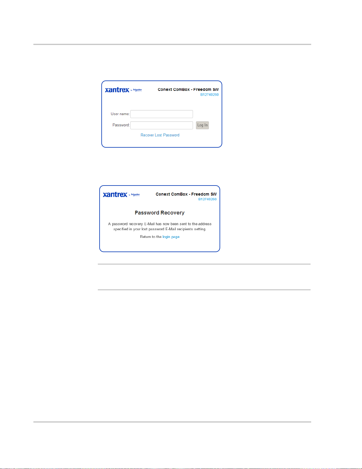
The first time you log in to the Conext ComBox web user interface, use the default
User name: admin and Password: password.
Two Ty p e s o f A c co u n t s
User name Password Privileges
admin password System-level access.
Lets you make changes to Conext ComBox
settings and Xanbus device settings, and
access all system monitoring, status, and
logging tools.
user user Limited access.
Lets you display system and status monitoring
tools, and make basic changes to the
Freedom SW configuration using the Basic
settings button on the Home screen.
975-0704-01-01 Revision A 3–3

Configuration
The Home screen appears after logging in successfully.
Note
: The Freedom SW has one AC input. Your ComBox will be configured to display
GRID or GENERATOR power flow (but not both at the same time).
Once you log in, click in the menu bar to change the password.
3–4 975-0704-01-01 Revision A

Changing the Admin Password
Change the password from the default “password” as soon as possible.
Changing the Admin Password
Changing the
Admin password
To change the Conext ComBox Admin Password:
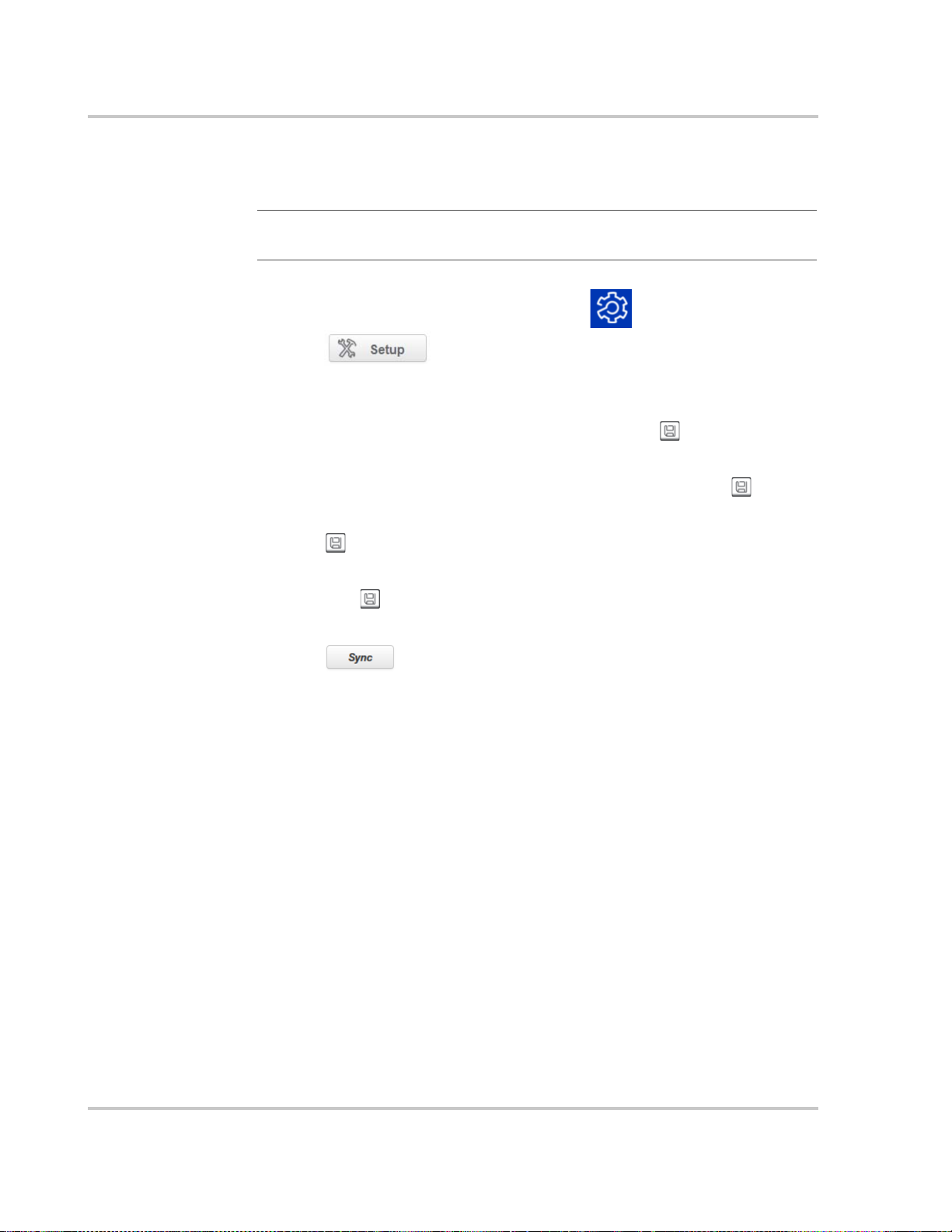
1. In the menu bar, click .
2. Click in the left side menu.
3. Under Conext ComBox Settings, click Change Admin Password.
4. Enter the Old Password.
5. Enter your New Password.
The password should contain at least eight alphanumeric (0-9, a-z, A-Z)
characters with no special characters and spaces. Passwords are casesensitive, and the maximum length is 32 characters.
6. Enter the New Password (confirm) again.
7. Click Submit.
A message indicates that the password change was successful.
975-0704-01-01 Revision A 3–5
Configuration
Recovering the
Admin password
.
To recover a Password:
If you forget the password, click Recover Lost Password in the Login window.
An e-mail will be sent to the designated e-mail address(es) containing the current
or a random temporary password for your Conext ComBox.
Note: You must have the Conext ComBox E-mail Settings configured and
connected to the internet for this feature to work. See “Changing E-Mail
Settings” on page 3–9’.
3–6 975-0704-01-01 Revision A

Changing the Time
WARNING
PHYSICAL INJURY HAZARD
Be careful when changing the Conext ComBox time setting. It will override any
time settings on individual Xanbus-enabled devices in the network. The time
represents the entire system. Any appliance or equipment that is timecontrolled by a Xanbus device, such as a generator connected to an AGS,
can inadvertently turn on at the wrong time.
Failure to follow these instructions can result in death or serious injury.
You can also choose to use the network time for your system. If enabled, network
time (SNTP) will override the Conext ComBox Time setting at the next SNTP
polling update. See “Using Network Time” on page 3–8. The default setting has
SNTP network time enabled (SNTP state is On).
Note: This date/time setting overrides settings on other devices in the system.
To set the Conext ComBox time and date:
Changing the Time
1. On the Home screen, click to display the Basic Settings control panel.
2. Click Time & Zone and then select the appropriate values. Click Submit.
975-0704-01-01 Revision A 3–7
Configuration
Using Network
Time
You can choose to use the network time for your Conext ComBox system. You
must be logged on as Admin to access Network Time and other advanced
settings.
: If you enable this option, it will replace any manual settings you set
Note
under Time and Zone at the next update according to the SNTP poll setting.
To use the network time and date:
1. Log in as Admin, and in the menu bar, click .
2. Click in the left side menu.
3. Under Conext ComBox settings, click Network Time (SNTP).
4. In SNTP Server Name, enter the IP address or URL of the network time
server, (pool.ntp.org is recommended) and then click .
5. In SNTP Poll Interval, enter (in hours) how often you want to update the
Conext ComBox system time to the network time and then click .
6. To enable the automatic network time setting, select SNTP State On and then
click .
To disable the automatic network time setting, select SNTP State Off and
then click .
7. To perform a manual network time synchronization (SNTP State must be On),
click under Perform SNTP Synchronization.
3–8 975-0704-01-01 Revision A

Changing E-Mail Settings
If you forget your password and want to have it sent to you, you must provide a
an e-mail address. Lost password recovery is not possible without first setting up
a valid e-mail address and enabling e-mail notification.
: E-mail Settings is a networking feature that requires a Local Area
Note
Network with Internet access. If you do not have Internet access through your
router, this feature is not available.
Changing E-Mail Settings
Mailer Status Activate or deactivate e-mailing
features. When enabled, a user who
forgets a password when trying to log
in can have the Conext ComBox send
the current password or a randomly
generated temporary password by
e-mail.
975-0704-01-01 Revision A 3–9

Configuration
E-mail Server Address Specify the mail server address
provided by the Internet service
provider. It has the format
mailserver.yourdomain.com. Contact
your Internet service provider for the
correct information.
E-mail Server Port Specify the port number used by a
computer to transmit electronic data
through the Internet. The number 25 is
typically reserved for e-mail.
E-mail Recipients Enter multiple e-mail addresses
separated by a comma and no space.
Any address listed here will receive email messages generated by the
Conext ComBox.
E-mail Authentication Enable or disable an external e-mail’s
authentication settings. When enabled,
you have to supply the E-mail User ID
and E-mail Password below.
E-mail User ID Specify the external e-mail account’s
user ID, which is usually the full e-mail
address that includes the domain
name.
E-mail Password Specify the external e-mail account’s
password.
Lost Password E-Mail Recipients Specify a valid e-mail address where
the current password or a random
temporary password can be sent.
For multiple e-mail recipients, separate
the addresses with a comma and no
space.
Lost Password E-Mail From Address Specify a valid e-mail address that can
be used as an identifier of the sender.
Generally, the sender is also the user of
the Conext ComBox.
By default, this is set to no-
reply@schneider-electric.com and
typically does not need to be changed.
Reset Lost Passwords Select No to send the current
password by e-mail.
Select Yes to generate a random
temporary password to be sent by
e-mail.
3–10 975-0704-01-01 Revision A

Connecting the Conext ComBox to the Xanbus Network
Send Test E-Mail Test that the e-mail settings above
have been configured correctly.
Press the button to send a
sample e-mail message to the
addresses listed in the E-mail
Recipients parameter. Mailer Status
must be enabled for the button to work.
Connecting the Conext ComBox to the Xanbus Network
After you install and configure the Conext ComBox, you can connect it to the
Xanbus network. The Xanbus network cable (a CAT5 cable), can provide both
data communication and power from Xanbus-enabled devices.
Important: Make sure the ComBox clock is configured before connecting
ComBox to the Xanbus network. See “Changing the Time” on page 3–7.
Xanbus is a valid power source for the Conext ComBox. However, for first-time
setup, it is not recommended. The Conext ComBox clock will override the other
Xanbus devices’ clocks and could trigger unintentional time-based events.
DO NOT connect the Conext ComBox to the Xanbus network before setting up
the internal clock of the Conext ComBox. If Xanbus is the only power source to
the ComBox, after installation verify the time settings in all devices.
When you connect the Conext ComBox to the network, the web application
automatically discovers any new Xanbus devices, and Modbus addresses are
assigned according to the starting address configuration settings. Log out of the
web user interface and then log in again to check the Modbus address for the
new device and its status.
When applying power to the Conext ComBox through the Xanbus network, make
sure the Xanbus network itself has power. Only Freedom SW inverter/chargers
can provide power to the Xanbus network and must be operating.
Note:
• Xanbus components can be arranged in any order.
• Use a network terminator at both ends of the Xanbus network.
975-0704-01-01 Revision A 3–11
Configuration
NOTICE
Network
Terminator
SCP AGS
Freedom SW
Freedom SW
Conext ComBox
Network
Terminator
Connect to Xanbus ports only
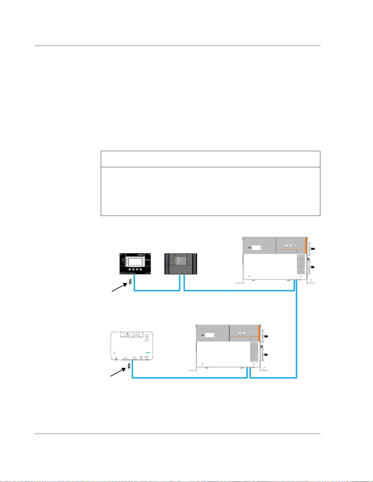
To connect the Conext ComBox to an existing Xanbus network:
The assumption at this point is that there is an existing Xanbus network and all
Xanbus-enabled devices in that network have been previously interconnected
with each other.
1. Put the Freedom SW inverter/chargers and Xanbus AGS into standby mode
before connecting the Conext ComBox to avoid triggering any unintentional
time-based events.
You can put the inverter/chargers out of standby mode later when you have
completed configuration of the Conext ComBox.
2. Using the sample illustration below, connect the Conext ComBox to the
Xanbus network.
EQUIPMENT DAMAGE
Do not connect a Xanbus RJ-45 cable plug into the 10/100 Ethernet port of the
Conext ComBox.
Failure to follow these instructions can damage equipment or affect
network performance.
Be sure to terminate the Xanbus network with Xanbus network terminators at both
ends.
SCP
TM
Fault kW Inverting
Batt
%
Low Battery Battery Type Search Battery Bank
Cutoff Mode Capacity (Ah)
AGM/
LOW HIGH GEL Flooded
Max Off
1000
30
800
600
FREEDOM
SW 2000
100
400
200
Fault kW Inverting
Batt
A Charging
%
Low Battery Battery Type Search Battery Bank
Cutoff Mode Capacity (Ah)
AGM/
LOW HIGH GEL Flooded
Max Off
1000
30
800
600
100
400
A Charging
FREEDOM
200
2000
SW
3–12 975-0704-01-01 Revision A

Changing Basic Conext ComBox Settings
Basic Freedom
SW Settings
When the Conext ComBox starts communicating with other Xanbus-enabled
devices on the network, the Xanbus LED will go on.
The Conext ComBox is now ready to configure, control, and monitor the devices
connected on the Xanbus network.
Changing Basic Conext ComBox Settings
To configure basic settings for one or more Freedom SW products, click
on the Home screen to display the control panel.
Note: The Freedom SW has one AC input. Your ComBox will be configured to display
GRID or GENERATOR power flow (but not both at the same time).
975-0704-01-01 Revision A 3–13

Configuration
Control Panel
In the control panel, adjust the following settings as needed, and click the close
button when done.
Select Enable to turn on the inverter. When the
inverter is on, any AC loads connected to it receive
power. Select Disable to turn off the inverter.
If there are two inverter/chargers in the system, this
setting applies to both devices.
Select Auto to automatically start or stop the
generator based on the settings selected in the
Xanbus AGS. These settings include triggers for low
battery voltage, AC loads on the inverter, thermostat
triggers and exercise time.
Select Manual On to override the automatic start
settings and start the generator. The generator will
run until manually stopped (Manual Off) or when it
reaches the Maximum Run Time setting defined in
the AGS.
Select Manual Off to override the automatic stop
settings and stop the generator when it has been
started manually (Manual On).
For information on AGS settings see the Xanbus
Automatic Generator Start Owner’s Guide.
Select the appropriate time and time zone from the
list to synchronize the ComBox and Xanbus SCP
internal clocks.
It is important for devices on the Xanbus network to
have the same system time. If the internal clocks are
not synchronized, timing-reliant devices such as the
AGS could start or stop unintentionally.
Note: This setting also sets the time and zone value
in the Settings screen. See “Changing Advanced
Conext ComBox Settings” on page 3–15.
3–14 975-0704-01-01 Revision A
Changing Advanced Conext ComBox Settings
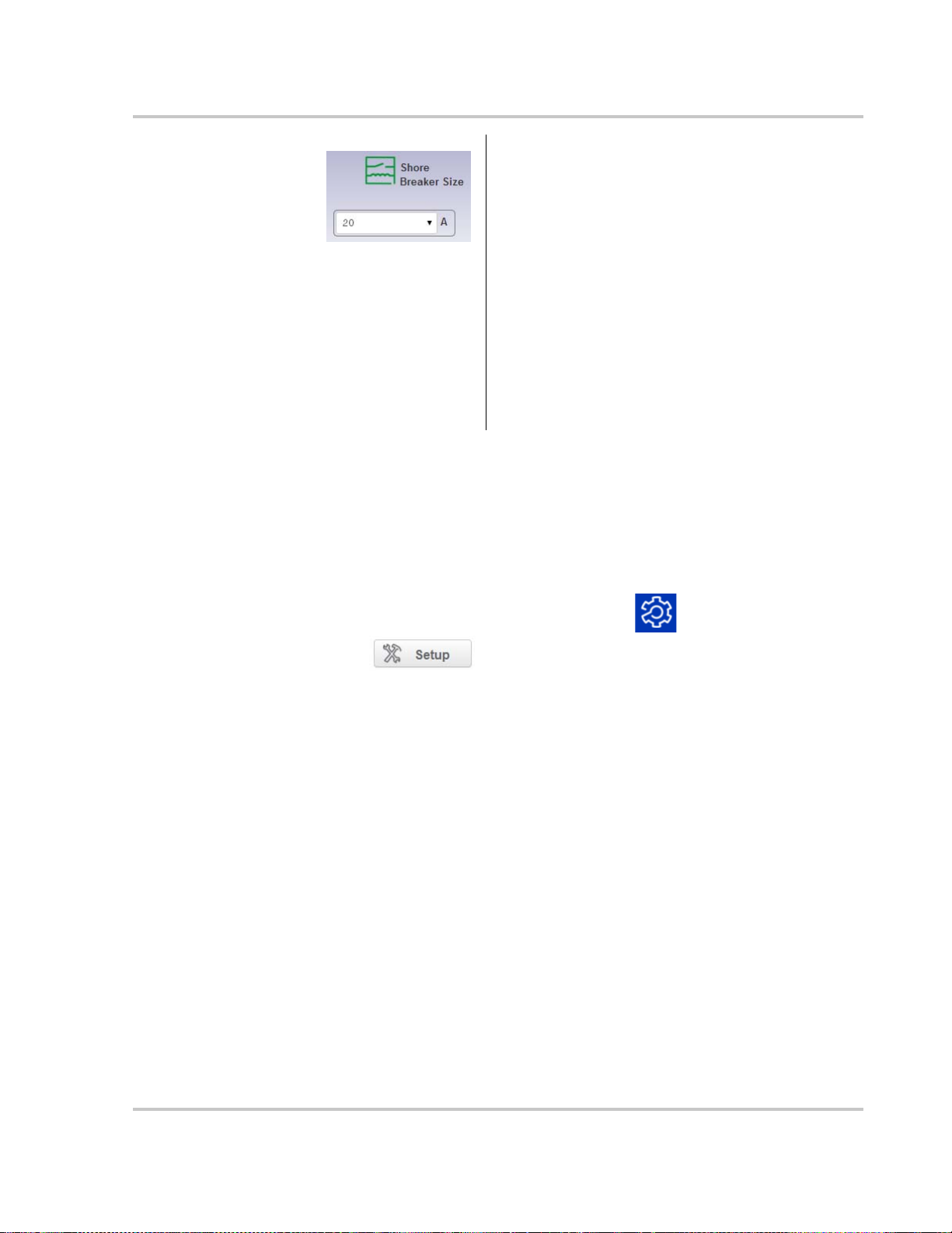
Set the amperage limit for the AC shore breaker
using the drop down list.
If the system has both a Freedom Sequence power
management system and a Freedom SW inverter/
charger installed, this setting applies to both
devices. If the system does not have a Freedom
Sequence, then only the Freedom SW inverter/
charger shore breaker size is set.
When input current exceeds the selected value, the
Freedom SW inverter/charger reduces its charge
current to limit the total power to 80% of this setting,
and the Freedom Sequence progressively sheds low
priority loads to avoid unnecessary tripping of the
AC shore breaker.
Changing Advanced Conext ComBox Settings
The section describes how to configure the advanced Conext ComBox
parameters. To access these settings, you must be logged in as Admin.
To access all Conext ComBox settings:
1. Log in as Admin, and in the menu bar, click .
2. Click in the left side menu.
You will see a screen similar to the one shown below.
975-0704-01-01 Revision A 3–15

Configuration
3. Click the setting type you want to change.
That portion of the window expands to display the change options for that
setting. The size and content of the expanded window varies depending on
the setting type.
General Settings
4. In the expanded window, click to see the current setting. This may be
different from the value shown if the change was made in another way.
5. Modify the value(s) as necessary.
6. Click to save the change(s).
3–16 975-0704-01-01 Revision A

Changing Advanced Conext ComBox Settings
Changing the
device name
Rebooting the
Conext ComBox
Shutting down the
Conext ComBox
The default Device Friendly Name is the device’s serial number assigned at the
factory. It is good practice to change this default to a user-friendly name.
To change the device name:
1. Replace the default value using alphanumeric characters.
2. Click to save the setting.
3. To recall the previous value, click .
You can reboot the Conext ComBox unit from the web user interface without
doing a power cycle. This type of “soft” rebooting is oftentimes necessary when
certain settings are changed, like changing the Xanbus Bit Rate parameter.
To reboot the Conext ComBox:
1. Click the button. A Warning dialog box appears.
2. Click the OK button on the Warning dialog box.
3. To discontinue rebooting, click the Cancel button on the Warning dialog box.
You should shut down the Conext ComBox unit from the web user interface.
Shutting down is equivalent to turning off the unit, usually for preparing to store
the unit away or to reinstall the unit at a different location.
Note: Do not shut down by abruptly disconnecting all power sources to the
Conext ComBox without following the procedure below. An abrupt disconnection
may result in data corruption.
To shut down the Conext ComBox:
1. Click the button. A Warning dialog box appears.
2. Click the OK button on the Warning dialog box.
3. To discontinue shutting down, click the Cancel button on the Warning dialog
box.
Change User Password Settings
The Change User Password setting applies only to the Conext ComBox user
account.
975-0704-01-01 Revision A 3–17
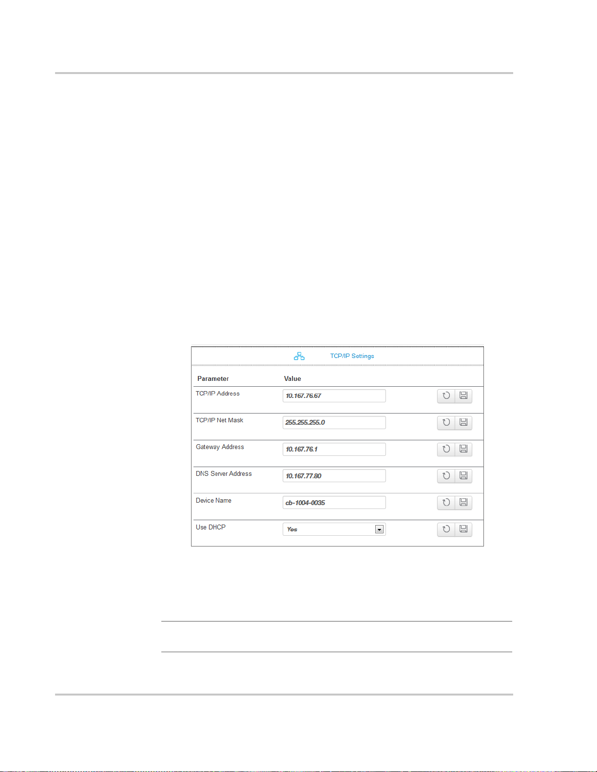
Configuration
To change the user password:
1. Enter the Old Password.
2. Enter your New Password.
The password should contain at least eight alphanumeric (0-9, a-z, A-Z)
characters with no special characters and spaces. Passwords are
case-sensitive and the maximum length is 32 characters.
3. Enter the New Password (confirm) again.
4. Click Submit.
A message indicates that the password change was successful.
Change Admin Password Settings
The Change Admin Password setting applies only to the Conext ComBox admin
account.
See “Changing the Admin Password” on page 3–5.
TCP/IP Settings
By default, the Use DHCP parameter is set to Yes. By enabling DHCP, the four
parameters (TCP/IP Address, TCP/IP Net Mask, Gateway Address, and DNS
Server Address) are filled automatically. If the Use DHCP parameter is set to No,
you have to manually fill the four parameters with static IP addresses.
Note: Only a qualified IT professional should perform changes to TCP/IP
related settings.
3–18 975-0704-01-01 Revision A

E-mail Settings
E-mail Reporting
Changing Advanced Conext ComBox Settings
See “Changing E-Mail Settings” on page 3–9.
Note: E-mail Settings is a networking feature that requires a Local Area
Network with Internet access. If you do not have Internet access through your
router, this feature is not available.
Note
: E-mail Reporting is a networking feature that requires a Local Area
Network with Internet access. If you do not have Internet access through your
router, this feature is not available.
975-0704-01-01 Revision A 3–19

Configuration
E-mail System Report Activate or deactivate system reporting
features. When activated (Yes), system
reports are sent electronically to
recipients listed in
E-Mail Recipients under E-mail Settings.
System Report Include (Included) or exclude (Not
Included) certain categories in the
system reports that are being sent. The
system reports are broken down into
different categories such as Generator
Energy, Load Energy, etc.
E-mail Device Report Activate or deactivate device-specific
reporting features. When activated (Yes),
device reports are sent electronically to
recipients listed in
E-Mail Recipients under E-mail Settings.
E-mail Report Frequency Change the frequency of reporting by
day, week, or month.
E-mail Report Day For weekly reporting, choose a day of the
week to receive system reports.
For monthly reporting, choose whether to
receive system reports at the last day of
each month or any particular day of the
month.
Send Test Report Test that the E-mail Settings in “Changing
E-Mail Settings” on page 3–9 have been
configured correctly.
Press the button to send a
sample e-mail message to the addresses
listed in the E-mail Recipients parameter.
3–20 975-0704-01-01 Revision A

Web
Changing Advanced Conext ComBox Settings
: Web is a networking feature that requires a Local Area Network with
Note
Internet access. If you do not have Internet access through your router, this
feature is not available.
If you want Web access to the Conext ComBox:
•In Web Server Access, select HTTP and then click .
If you do not want Web access to the Conext ComBox:
•In Web Server Access, select Disabled and then click .
The default value of the Web Server Port is 80. If this value is changed to 8080,
you must append the URL address with “:8080” at the end of the IP address.
Note: You must restart ComBox after changing the Web Server Port.
Note
: If the Web server is disabled (for example, for security reasons), the Web
server will not be available on the next reboot of the Conext ComBox. To regain
access to the Web server, “Resetting the Conext ComBox to Factory Settings” is
necessary to make configuration changes.
975-0704-01-01 Revision A 3–21
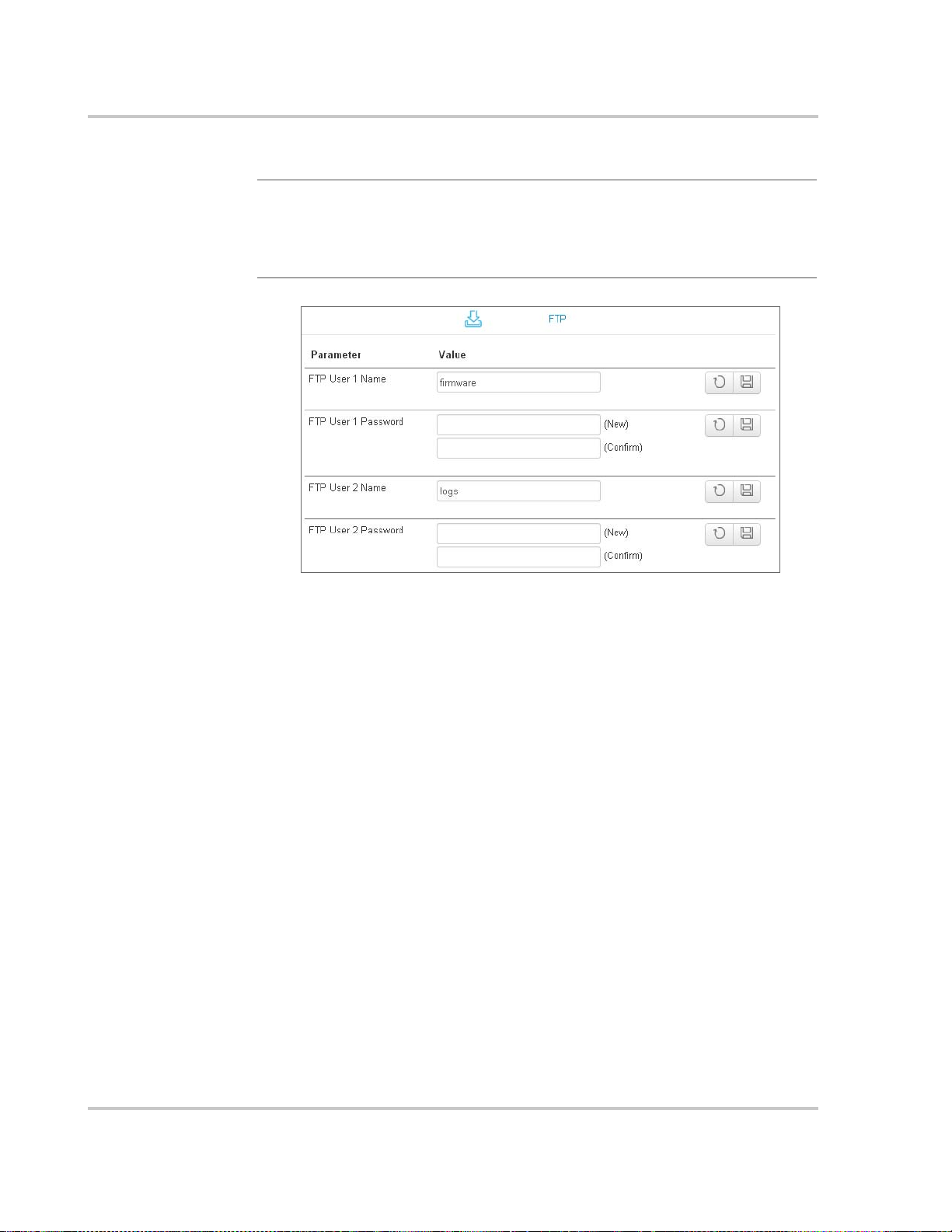
Configuration
FTP
Note
: FTP is a networking feature that requires a Local Area Network with
Internet access. If you do not have Internet access through your router, this
feature is not available.
This setting is for advanced users only.
Use for updating
firmware
Use for
downloading logs
The FTP User 1 Name and FTP User 1 Password are used for firmware
upgrades. By default, the password is the same as the user name so it must be
changed.
For upgrades go to:
• http://xantrex.com/power-products/default/conext-combox-freedomsw
The FTP User 2 Name and FTP User 2 Password are used to download log
information. By default, the password is the same as the user name so it must be
changed.
3–22 975-0704-01-01 Revision A
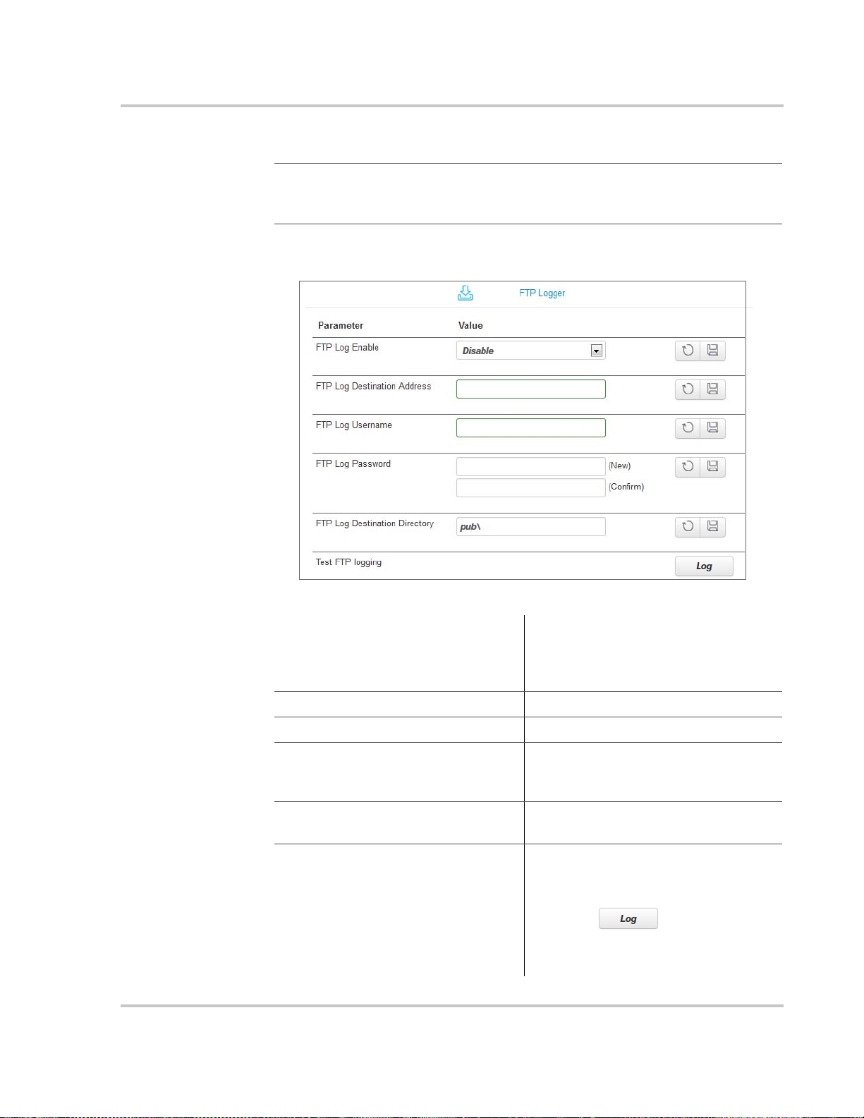
FTP Logger
Changing Advanced Conext ComBox Settings
Note
: FTP Logger is a networking feature that requires a Local Area Network
with Internet access. If you do not have Internet access through your router, this
feature is not available.
This setting allows the user to push event and detected fault logs to an FTP site.
FTP Log Enable Activate or deactivate FTP logging
features. When activated (Enable), FTP
logs are sent electronically to an FTP
site.
FTP Log Destination Address Specify a valid FTP site.
FTP Log Username Specify the FTP site’s valid user name.
FTP Log Password Specify the FTP site’s valid password in
the (New) field. Repeat the password
in the (Confirm) field.
FTP Log Destination Directory Specify a valid directory on the FTP
site where all the logs will be stored.
Test FTP Logging Test that the FTP Logger settings have
been configured correctly.
Press the button to send a
sample log to the FTP site specified in
FTP Log Destination Address.
975-0704-01-01 Revision A 3–23

Configuration
Dry Contact Relay
You can set the Relay Mode of Operation to Automatic so that the relay will
automatically go on if a fault is detected in the system.
To manually control the mode of operation so that the relay is always on (or off),
select On (or Off).
Suppress Device Faults/Warnings
You can suppress certain fault and warning codes from being included in the
device reports that are sent to E-Mail Recipients specified in E-Mail Settings.
List the fault and warning codes for each device you want to exclude in the report
by entering the name of the code. Separate multiple codes by comma.
The fault and warning codes for all the devices are usually listed under the
Troubleshooting section of the device’s Owner’s Guide.
3–24 975-0704-01-01 Revision A
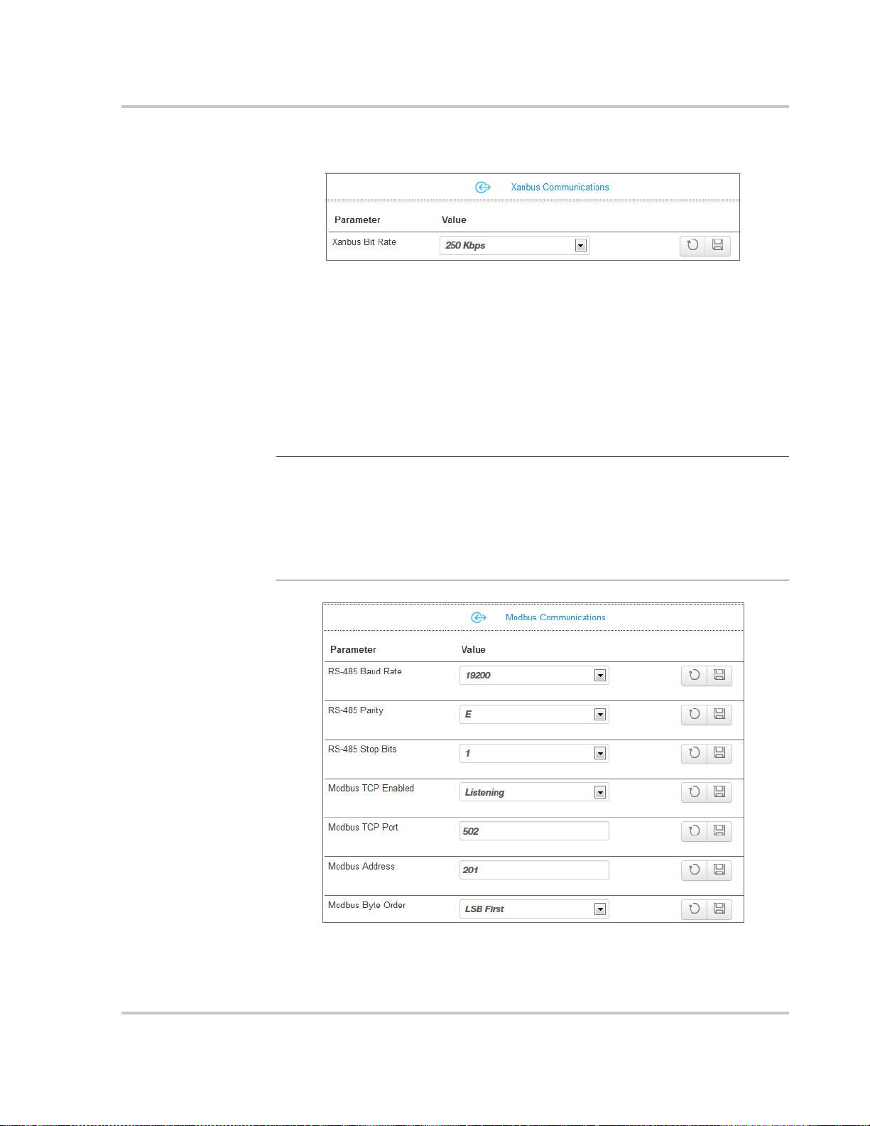
Xanbus Communications
The Xanbus Bit Rate parameter for the Conext ComBox has two possible
values: 125 and 250 Kbps. The default value for the Xanbus Bit Rate is
250 Kbps. When this setting is changed, reboot the Conext ComBox for the new
setting to take effect. See “Rebooting the Conext ComBox” on page 3–17.
Freedom SW devices and components require a 250 Kbps bit rate. You cannot
change the bit rate for Freedom SW system devices and components.
Modbus Communications
Note: Modbus support is available only for the Conext ComBox (Part Number
865-1058), and Conext Modbus Converter (Part Number 865-1059), used with
Schneider Electric Conext series inverter products.
Changing Advanced Conext ComBox Settings
The Modbus Communications option available with this Conext ComBox –
Freedom SW (Part Number 809- 0918), is not required for operation or
supported by Xantrex technical support.
975-0704-01-01 Revision A 3–25
Configuration
OETCNX
CNXOET
12345678
56781234
Modbus Byte Order
All of the RS 485 and Modbus settings for the Conext ComBox can be changed
as necessary. The default value for the Modbus TCP Port is 502 and the Server
Modbus Address is 201.
Select Listening in Modbus TCP Enabled to enable Modbus communication.
Note
:
When writing a character string using function code 0x10 (Write Multiple
Registers), the NUL terminator MUST be written or the string will not be stored.
When writing 32-bit modbus registers, both 16-bit registers which make up the
32-bit value must be written in order to store the data.
You can configure the Conext ComBox to change the Modbus byte and word
ordering for packed ASCII strings, and 32-bit values. There are two settings for
Modbus Byte Order:
1. Least Significant byte/word first (LSB First)
2. Most Significant byte/word first (MSB First)
Select the appropriate setting for your Modbus network.
Packed String
Example:
32-bit Word
Example:
The following are examples of how the settings operate.
When sending the text string "CONEXT" over Modbus:
1. Least Significant byte:
2. Most Significant byte:
When sending the value 0x12345678 over modbus:
1. Least Significant word:
2. Most Significant word:
3–26 975-0704-01-01 Revision A

Modbus Address List
Note
865-1058), and Conext Modbus Converter (Part Number 865-1059), used with
Schneider Electric Conext series inverter products.
The Modbus Address List option available with this Conext ComBox – Freedom
SW (Part Number 809- 0918), is not required for operation or supported by
Xantrex technical support.
Use this function to change the Modbus address of a device. The Conext
ComBox automatically assigns addresses when it is installed, but individual
values can be changed as necessary. The default addresses are assigned per
device type.
Note: To change the initial starting address settings, see “Modbus Address
Enumeration”.
Changing Advanced Conext ComBox Settings
: Modbus support is available only for the Conext ComBox (Part Number
To change a device Modbus address:
1. In Setup, click Modbus Address List.
The expanded window displays a table of addresses that are already
reserved along with the associated device, its ID and On Line status.
Note: Valid Modbus addresses are listed from 1 to 247. The rest are assigned
special meanings.
2. To change a device Modbus address:
• Select the Device from the drop-down list.
Its address is displayed in the address box.
If you want to make sure you have selected the correct device:
975-0704-01-01 Revision A 3–27
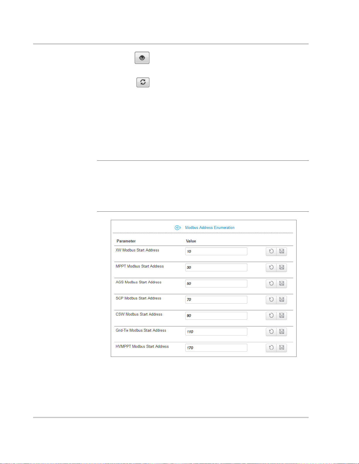
Configuration
Click and a physical indicator on the device will flash, light up, or
beep depending on the device.
• Click to make sure you view the latest information.
• Enter the new address for the device in the address box. Do not use an
address that is already reserved.
• Click Submit to save the address change.
To reset all of the device Modbus addresses to their default values:
u In Modbus Address List, click Reset Addresses.
Modbus Address Enumeration
Note: Modbus support is available only for the Conext ComBox (Part Number
865-1058), and Conext Modbus Converter (Part Number 865-1059), used with
Schneider Electric Conext series inverter products.
The Modbus Address Enumeration option available with this Conext ComBox –
Freedom SW (Part Number 809- 0918), is not required for operation or
supported by Xantrex technical support.
Use this setting to change the initial starting Modbus addresses for device types.
The Conext ComBox automatically assigns starting addresses when it is installed
but the starting values can be changed as you wish.
3–28 975-0704-01-01 Revision A

Changing Advanced Conext ComBox Settings
Make these changes before connecting new devices to the Conext ComBox
system. When the Conext ComBox detects a new device, it will assign the
address based on the current start address setting for that device type.
For example, a Freedom SW Modbus Start Address of 10:
• The first Freedom SW discovered on the network will be assigned the
address 10.
• The second Freedom SW discovered on the network will be assigned the
address 11, and so on.
The starting addresses for each device type on installation of the Conext
ComBox are listed above.
To change device type starting addresses:
1. In Modbus Device Address Enumeration, click for the device type to
ensure you have the current information.
2. Enter the new starting value for the device type and click .
Note: Valid Modbus addresses can be from 1 to 247. The rest of the numbers
are assigned special meanings.
3. Once you have saved all device type starting addresses, there are two
options:
• You can keep the existing device addresses, and the new start address
will be applied only to newly discovered devices.
When a new device is detected, the Conext ComBox determines the
starting address of that device type, finds the first unused address for
that device type, and assigns this address to the new device
• The Conext ComBox can perform a device rediscovery to reassign
addresses based on the changed starting addresses.
To reassign new addresses to all devices:
In Modbus Address List, click Reset Addresses. Then, perform a reboot
(see “Rebooting the Conext ComBox” on page 3–17).
975-0704-01-01 Revision A 3–29

Configuration
quick flashes
10 seconds
elapsed time
System Diagram
Use this setting to include (checked box) or exclude (unchecked box) system
diagrams of each electrical system component as displayed in the Home screen.
Resetting the Conext ComBox to Factory Settings
If you need to return the Conext ComBox to all of the original factory settings, you
can perform a reset.
To reset the Conext ComBox to original factory settings:
1. Turn off the Conext ComBox by shutting it down properly (as shown on
page 3–17) and then disconnecting all its power sources. Make sure the
Power LED is off. Wait ten seconds before the next step.
To turn the unit on, insert a pointed object such as a paper clip into the Reset
pinhole, and press the button while reconnecting the Conext ComBox’s
power source.
2. Continue pressing (holding) the Reset pinhole button until all indicator LEDs
flash quickly five times (approximately 10 seconds) and then quickly release
the button.
3–30 975-0704-01-01 Revision A
Important: Do not hold the reset button too long after observing the quick
NOTICE
flashes. When you observe that the indicator LEDs have begun flashing slowly,
the internal firmware memory will have already been cleared. There is no way to
undo this except to do an upgrade. See “Upgrading Firmware” on page 3–35.
Note
: The Power LED flashes slowly during the Conext ComBox application
loading and flashes quickly during application initialization. The other LEDs go
on as the startup progresses. This process takes about two minutes.
3. When the reset is complete, the Power indicator is on to indicate the Conext
ComBox is ready.
Changing Device Settings
The Conext ComBox allows you to configure settings on the Freedom SW,
Xanbus SCP and Xanbus AGS.
Before making any changes, familiarise yourself thoroughly with the effects of
changing the power system settings.
Changing Device Settings
EQUIPMENT DAMAGE
• Consult the device’s Owner’s Guide when changing the device’s settings.
• Make sure the device connected on the Xanbus or Modbus network is in
standby mode before changing settings.
• Do not change any settings unless you are familiar with the device.
Failure to follow these instructions can damage equipment.
To set a device in Standby mode:
1. Click the Devices icon to show all Xanbus devices in the network.
2. Select the device type from the Devices screen.
975-0704-01-01 Revision A 3–31

Configuration
3. Click the device you want to change from the Devices screen above.
The Device Summary Table screen opens. If there are more than one of the
same device type, the devices will be listed in the summary table.
4. Click the Freedom SW, SCP, or AGS you want to change from the summary
table. The Device Status screen opens.
3–32 975-0704-01-01 Revision A

5. Click in the left side menu.
Changing Device Settings
6. You will see a list of Device Settings for that type of device.
7. Click to expand the Controls setting.
8. Change the Operating Mode parameter to Standby.
9. Click to save the setting.
To change a Device Setting after putting the device on Standby:
1. After putting a device on Standby mode, proceed to change the device’s
other settings.
Important: Device settings for each Xanbus device vary. Be sure to consult the
device’s Owner’s Guide before trying to change the settings via the Conext
ComBox.
975-0704-01-01 Revision A 3–33

Configuration
2. Click the Device Setting type you want to change.
That portion of the window will expand to display the change options for that
setting.
3. In the expanded window, click to see the current setting. This may be
different from the value shown, if the change was made in another way – for
example, another device like the SCP was used to change the value.
4. Modify the value(s) as necessary.
5. Click to save the change(s).
Using Cascading Parameters
Xanbus-enabled devices are typically configured one at a time. However,
because devices often have common settings, cascading parameters can
simplify and speed up system configuration. When a parameter is “cascaded,” a
newly configured device setting on one device is applied to all devices of the
same device type on a common AC or DC connection.
For example, if cascading parameters are enabled and a Battery Size (Ah)
parameter is changed on the Freedom SW inverter setup menu, the same battery
size setting is applied to the second inverter.
To enable or disable cascading parameters:
1. Put the device on standby mode. See “To set a device in Standby mode:” on
page 3–31.
2. Click to access the individual devices menu.
3–34 975-0704-01-01 Revision A

Upgrading Firmware
3. Click the device you want to configure.
4. Click in the left side menu to see a list of Device Settings for
that type of device.
Important: Device settings for each Xanbus device vary. Consult the device
Owner’s Guide before trying to change the settings via the Conext ComBox.
Also, when configuring the network-managed power system with cascading
parameters enabled, you should verify that the configurations have been
cascaded correctly to other devices. Communication errors may cause
parameters to revert to their original values or generate a warning message.
5. Click to expand the device setting.
6. Click the check box to enable the setting. If the box is already checked then
cascading is already set up and no further action is necessary.
7. Click to save the change.
Upgrading Firmware
You can perform firmware upgrades for your Conext ComBox and Xanbusenabled devices when they are available for download. You can download them
to a USB thumb drive, or to a laptop that you then connect to the Conext
ComBox.
Firmware upgrades are available at:
• http://xantrex.com/power-products/default/conext-combox-freedomsw
Note: It is recommended you clear the internal firmware memory of the Conext
ComBox before installing firmware upgrades.
975-0704-01-01 Revision A 3–35

Configuration
Quick flashes
Slow flashes
10 seconds
elapsed time
5 seconds
elapsed time
Continue to hold the Reset pinhole
to bypass the Reset to Factory
Settings procedure.
The Upgrading Firmware
procedure starts here.
Clearing the Internal Firmware Memory
Note
: Clearing internal firmware memory should be done for Conext ComBox
upgrades only. It is not necessary for upgrades to other devices on the network.
To clear the Conext ComBox internal firmware memory:
1. Turn off the Conext ComBox by shutting it down and disconnecting all its
power sources. Make sure the Power LED is off. Wait ten seconds before the
next step.
2. Insert a pointed object such as a paper clip into the Reset pinhole and press
the button while turning on the Conext ComBox by reconnecting to its power
source.
3–36 975-0704-01-01 Revision A
3. Continue holding the Reset pinhole button until all indicator LEDs flash
quickly five times (approximately 10 seconds). Continue to hold the button
until the LEDs flash slowly (approximately 5 seconds). When the memory has
been cleared, the Status and Power LEDs are on and a firmware upgrade
must be done.

Installing Conext ComBox Upgrades from a Thumb Drive
To install an upgrade for the Conext ComBox using a thumb drive:
1. Connect the thumb drive to a computer with Internet access.
There must be only one .bdl file on the thumb drive. If there are two or more
.bdl files, there is no guarantee which .bdl file will be chosen.
2. In a web browser, go to the following website to select the upgrade you
need:
http://xantrex.com/power-products/default/conext-combox-freedomsw
3. Once you have found the upgrade, save the .bdl file to the root directory of
the thumb drive.
Note
: Save the .bdl file to the root directory of the thumb drive so the upgrade
can install properly.
4. Clear the Conext ComBox internal memory. See “Clearing the Internal
Firmware Memory”.
Connect the thumb drive to the USB port labeled Host on the top front of the
Conext ComBox.
Upgrading Firmware
The firmware upgrade begins automatically.
5. Watch the indicator LEDs on the Conext ComBox. When the Xanbus LED
goes on, it is now okay to remove the thumb drive.
As the upgrade progresses the Power LED flashes. The other LEDs go on to
indicate the upgrade process. This can take several minutes depending on
the size of the upgrade.
6. When the upgrade is complete, the Power LED is on to indicate that the
Conext ComBox is ready.
7. Clear your computer’s web browser cache after the upgrade before you log
back in to the Conext ComBox’s web user interface.
Clearing a web
browser’s cache
975-0704-01-01 Revision A 3–37
To clear the web browser’s cache:
1. In PC-based web browsers, press the keyboard shortcut
.
2. In the dialog box that opens (varies for each web browser), select an option
to clear temporary Internet files or “cache”.

Configuration
3. For Mac’s Safari web browser, go to Preferences and then to Security.
3–38 975-0704-01-01 Revision A
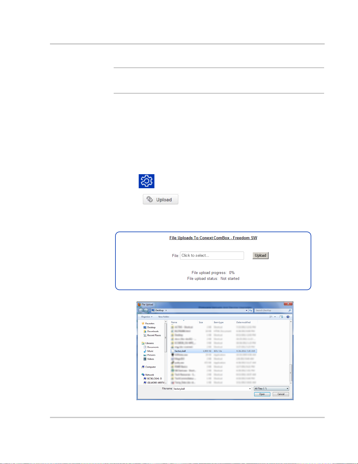
Installing Conext ComBox Upgrades Remotely
Note
: Internet Explorer 8.0 and 9.0 do not support firmware upgrades. Use
Chrome 18.x or later, IE 10.x or later, Firefox 12 or later, or Safari 5.x or later for
Conext ComBox upgrades.
To install a Conext ComBox upgrade remotely:
1. In a web browser, go to the following website to select the Conext ComBox
upgrade you need:
http://xantrex.com/power-products/default/conext-combox-freedomsw
2. After you find the upgrade, save the .bdl file in a local directory.
3. In your web browser, connect to your Conext ComBox.
4. Log in to the Conext ComBox web user interface with your user name and
password.
5. Click in the menu bar.
6. Click in the left side menu.
Upgrading Firmware
7. In File under File Uploads to Conext ComBox, click the field box to select the
.bdl file (factory.bdl) you saved in a local directory from the Xantrex website.
975-0704-01-01 Revision A 3–39

Configuration
8. Click Upload, and then OK in the warning dialog box.
As the bundle is transferred to the Conext ComBox, progress is indicated in
percentage, and a message screen indicates when the file transfer has been
completed successfully.
When the bundle file has transferred to the Conext ComBox, the files in the
bundle are automatically extracted and reprogramming of the Conext
ComBox begins.
9. Clear your web browser cache before you log back in to the Conext
ComBox’s web user interface. See “Clearing a web browser’s cache” on
page 3–37.
10. Reboot the Conext ComBox. See “Rebooting the Conext ComBox” on
page 3–17.
Bootloader
Upgrade
What happens when a new bootloader is included in the upgrade file?
It is possible that the bundle file may also contain a bootloader upgrade file. To
find out, you need to log back in and follow these instructions.
1. In your web browser, connect to your Conext ComBox.
2. Log in to the Conext ComBox web user interface with your user name and
password.
3. Click in the menu bar.
4. Click in the left side menu. If a new bootloader is included in
the bundle file, you are automatically prompted to update the Conext
ComBox bootloader.
5. Click OK, and wait while the bootloader upgrade progress completes. The
Conext ComBox restarts automatically when the upgrade is finished.
6. Clear your web browser cache before you log back in to the Conext
ComBox’s web user interface. See “Clearing a web browser’s cache” on
page 3–37.
3–40 975-0704-01-01 Revision A

Installing Xanbus Device Upgrades
You can upgrade firmware for specific Xanbus-enabled devices remotely or from
a computer connected to the Conext ComBox with the USB cable supplied.
Note
: Your Web browser may not support the upgrade function. Use Chrome
18.x or later, IE 10.x or later, Firefox 12 or later, or Safari 5.x or later for Conext
ComBox upgrades.
To install upgrades for Xanbus devices connected to the Conext ComBox:
1. In a Web browser, go to http://www.xantrex.com to select the device upgrade
that you need.
2. Once you have found the upgrade, save the .xf0 file in a local directory.
3. In your Web browser, connect to the Conext ComBox.
4. Log in to the Conext ComBox web user interface with your user name and
password.
5. Click in the menu bar.
6. Click in the left side menu.
Upgrading Firmware
7. In File under File Uploads to Conext ComBox, click to select the .bdl file you
saved from the Xantrex website.
8. Once the file is successfully transferred to the Conext ComBox, go to the
Xanbus Device Upgrades section.
9. In Device, click to load the latest list of devices.
10. Select the Device you want to upgrade from the drop-down list.
You can click to confirm you have selected the device you want.
When you click the icon, some type of visual and/or audio indicators on the
selected device will flash.
11. In Firmware file, select the .xf0 file for the device upgrade.
12. Click Upgrade.
Device upgrade progress is indicated in percent and Device upgrade status
is OK when the upgrade has completed successfully.
975-0704-01-01 Revision A 3–41

Configuration
If the device upgrade is not successful, click Upgrade again to retry.
If retrying does not work:
• Do a power cycle of the Xanbus device that is being upgraded.
• Then, click Upgrade on the web interface.
3–42 975-0704-01-01 Revision A

4 Monitoring
Chapter 4 describes the many ways the
Conext ComBox – Freedom SW can monitor
system components.
It includes:
• Monitoring LEDs
• Monitoring Conext ComBox Status
Information
• Monitoring System Components
• Managing Data Logs
975-0704-01-01 Revision A 4–1

Monitoring
Monitoring LEDs
LED indicators allow you to monitor the functioning of the Conext ComBox. There
are five LEDs in the upper right corner of the Conext ComBox:
• Power
•Memory
•Xanbus
• Modbus
• Status
All LED indicators are green except for the amber Status indicator.
Startup
The Power LED flashes slowly when the Conext ComBox application is loading
and flashes quickly during application initialization. The other LEDs illuminate as
startup progresses. Once the Conext ComBox is ready, the Power LED turns on
steadily. This process takes about two minutes.
4–2 975-0704-01-01 Revision A

Operating Mode
Monitoring Conext ComBox Status Information
The LED states and descriptions are listed in the following table.
Indicator State Description
Power On Powered and ready to communicate
Flashing The Conext ComBox is rebooting
Memory Flashing Logging data to internal memory
Xanbus On Actively communicating or transferring data
with the Xanbus network
Modbus Flashing Receiving messages from a Modbus master,
one flash per message
Status On Checking the status on a Xanbus device or the
Conext ComBox. Checking the web user
interface status screen to identify the current
state of the device or checking the e-mail for
reported faults
Monitoring Conext ComBox Status Information
You can view the current settings for the Conext ComBox without making
changes.
To view Conext ComBox Status Information:
1. Click in the menu bar.
2. Click in the left side menu to display the status information
screen.
975-0704-01-01 Revision A 4–3

Monitoring
3. Click the setting type you want to view.
The selected setting expands to display the options for that setting as shown
in the following screen. The size and content of the expanded window varies
depending on the setting type.
Modbus Address
List
Note: Modbus support is available only for the Conext ComBox (Part Number
865-1058), and Conext Modbus Converter (Part Number 865-1059), used with
Schneider Electric Conext series inverter products.
The Modbus Address List displayed with this Conext ComBox – Freedom SW
(Part Number 809- 0918), is not required for operation or supported by Xantrex
technical support.
Web Application
Version
Conext ComBox
Version
Device Information Displays information about the Conext ComBox hardware such as the Device
Displays information about the Conext ComBox web user interface. It shows the
build and version number.
Displays information about the Conext ComBox firmware. It shows the
application version and its build date. It also shows the bootloader version and
its build date.
name. It shows the model number, serial number, and hardware revision number.
It also shows the MAC address, IP address, and hostname.
4–4 975-0704-01-01 Revision A
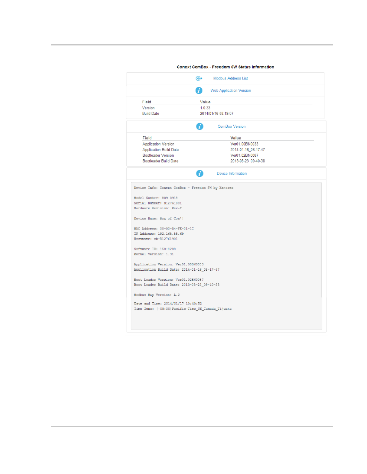
Monitoring Conext ComBox Status Information
Note: The information
displayed in these
examples will be
different from those in
your Conext ComBox.
975-0704-01-01 Revision A 4–5

Monitoring
Monitoring System Components
The system components are: devices, battery, loads, grid, solar, and generator.
• Devices - refers to the Xanbus units, such as inverter/chargers, automatic
generator starters (AGS), and system control panels (SCP).
• Battery - refers to the total energy stored in the battery system. It monitors
energy during charging as well as discharging.
• Loads - generally refers to total energy that is being used by electrical
appliances and machines directly connected to the inverters in the system. It
is not a specific appliance or machine.
• Grid Support- not available in this version of Conext ComBox – Freedom SW.
• Solar - reserved for future use. A Xanbus-enabled solar charge controller
certified for use on vehicles and boats is not currently available.
• Generator - refers to energy that is produced by a generator and accepted in
the system.
Devices
When you click the Devices icon you obtain direct access to all individual
Xanbus-enabled devices, allowing you to monitor and configure the settings of
each Xanbus-enabled device. Your commands are communicated from the web
user interface to each device, effectively controlling them remotely.
To access a Xanbus-enabled device:
1. Click the Devices icon from the home screen or menu bar. The Devices
screen opens.
4–6 975-0704-01-01 Revision A

Monitoring System Components
use for information
and monitoring
use for control and
configuration
2. Click the device you want to monitor or control from the Devices screen.
The Device Summary Table screen opens up. If there are more than one of
the same device type, the devices will be listed in the summary table.
3. Click the specific device listed in the summary table that you want to monitor or
change settings. The Device Status screen opens.
The Device Status screen is the initial screen. Click in the left
side menu if you want to return to this screen after navigating away from it.
975-0704-01-01 Revision A 4–7
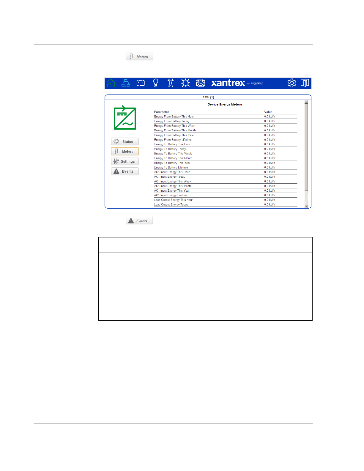
Monitoring
NOTICE
4. Click in the left side menu, if you want general energy-related
information gathered by the device, such as energy consumption, output,
and load.
5. Click in the left side menu, if you want information about faults
and warnings reported by the device.
EQUIPMENT DAMAGE
• Consult the device Owner’s Guide when changing the device’s settings.
• Ensure that the Xanbus-enabled device connected to the network is in
standby mode before changing settings. See “To set a device in Standby
mode:” on page 3–31.
• Do not change any settings unless you are familiar with the device.
Failure to follow these instructions can damage equipment.
4–8 975-0704-01-01 Revision A

Monitoring System Components
6. Click in the left side menu.
You will see a list of Device Settings for that type of device.
7. Before making any changes, put the device on standby mode. See “To set a
device in Standby mode:” on page 3–31.
8. Change the settings accordingly.
975-0704-01-01 Revision A 4–9

Monitoring
aggregate energy
information
real-time system
readings
Y-axis
X-axis
2nd data
series
1st data
series
interval
setting
1st calendar controls 2nd calendar controls
graph type
setting
data area
objects
Note: For a description of each graph element refer to the following table on page 4–11.
System Component Energy Graphs
Each of the system components, except Devices, generates an interactive
energy graph that allows you to monitor energy readings of the Battery, Loads,
and Generator. Aggregate energy information collected on a daily, weekly,
monthly, and yearly basis can be displayed for each of the components using
bar and line graphs. Using the graphs as an aid, you can analyze your system’s
performance and maximize its energy consumption. You can make decisions on
effective load management, and find areas for energy efficiency.
4–10 975-0704-01-01 Revision A

Monitoring System Components
Graph Element Description
Aggregate Energy Information Displays total energy used by the system component. It accumulates
data on a daily, weekly, monthly, yearly, and lifetime basis.
• Daily aggregates information collected at the start of the day
(12:00AM), up to the most recently completed hour.
• Weekly aggregates data starting from the most recent Sunday
up to the most completed day to date.
• Monthly sums up all information for the current month from day
1 up to the most completed day to date.
• Yea rl y sums up all information for the current year from month 1
up to the most completed month to date.
• Lifetime aggregates all data collected from the very beginning
the system started.
Important: Energy aggregation is based on the data collected by
ComBox. Actual lifetime energy for each device may differ.
Real-Time System Readings Displays real-time information on the system component selected.
Data Area This is where the graph is presented. If you hover the mouse pointer
over the data area, an information bubble containing information on the
object displays.
X-Axis The X-axis label generally represents time. The tick mark labels on the
X-axis change depending on the time Interval Setting selected. For
example, if the Interval Setting is Hours, then the tick mark labels will
be each hour of the day starting from 12:00 AM.
Y-Axis The Y-axis label is Energy in watt-hours (Wh). The tick mark labels on
the Y-axis adjusts accordingly. For example, if the watt measurement
expands to kilowatts, then the labels will appear with a “k”.
Data Series There are two data series. This means that you can display two
different data sets which you can analyze and compare.
The 1st Data Series (represented in Orange) always pertains to a data
set or data sets belonging to the system component selected. For
example, if the system component is Battery, then the 1st Data Series
could either be Battery Charge or Battery Discharge. For sources like
Generator, which have power flow in only one direction, there will be
only “input” energy viewable in the 1st Data Series.
The 2nd Data Series (represented in Blue) pertains to data sets
belonging to all the system components. Collectively, the data sets of
all system components are
and Battery Charge.
Calendar Controls There are two calendar controls. The 1st Calendar Controls (also in
Orange) is meant for the 1st Data Series. The 2nd Calendar Controls (in
Blue) is for the 2nd Data Series.
The controls are the left arrow, right arrow, and the calendar pop up link
in between the two arrows. When you click the calendar pop-up link, it
displays a calendar selector application.
975-0704-01-01 Revision A 4–11
Load Output, PV Input, Battery Discharge,
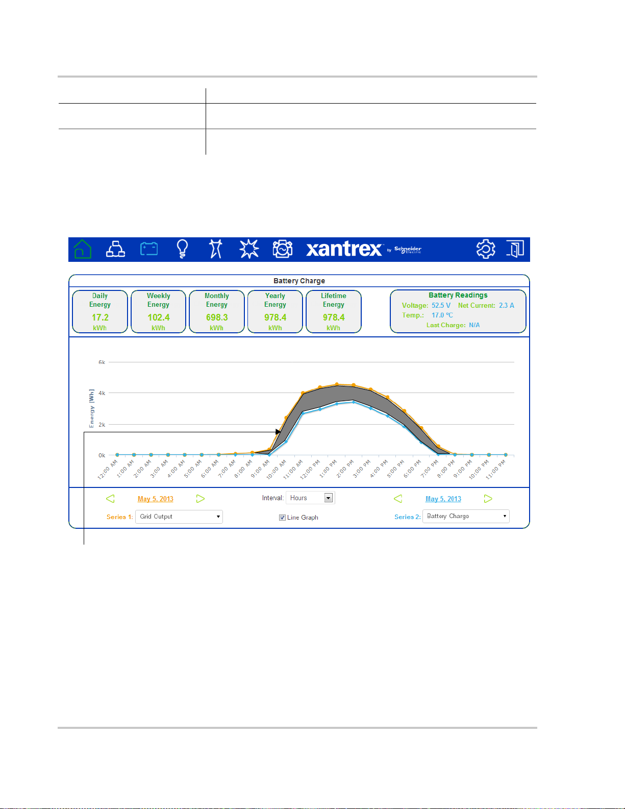
Monitoring
Observation #1: This is net energy that is
consumed by loads that are backed up by
Freedom SW inverters.
Graph Element Description
Interval Setting The interval setting changes the Y-axis label to one of four choices:
Hours, Days, Months, or Years.
Graph Type Setting By default, the graph displays bars. You have the option to display a
line graph simply by selecting the check box next to the Line Graph.
Interpreting a Battery Energy Graph
This graph compares energy from shore power (Series 1) versus energy that is
stored during charging (Series 2).
4–12 975-0704-01-01 Revision A

Interpreting a Load Energy Graph
Observation #1: The loads
are receiving pass-through
energy from the grid (shore
power).
Observation #2: The system is disconnected from shore power and is running off the battery.
This graph compares energy consumed by system loads versus energy received
from the utility grid (shore power).
Monitoring System Components
975-0704-01-01 Revision A 4–13
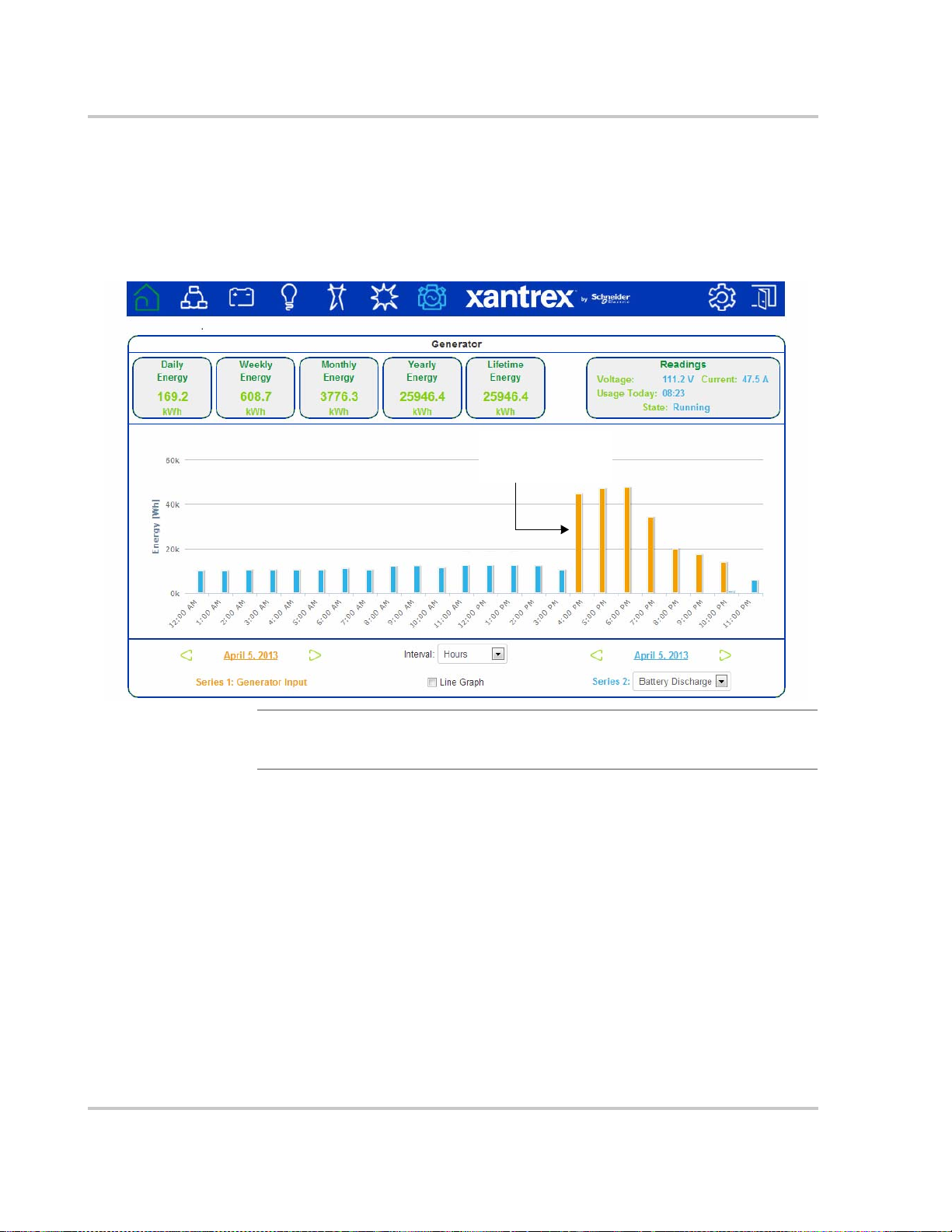
Monitoring
Observation #1: Shows that
around 4pm, the generator
was turned on and kept
running until 10pm.
Interpreting a Generator Energy Graph
This graph compares the total generator input versus battery discharge for a site
operating in a diesel cycle charging application. The baseload was
approximately 10-12 KW average throughout the day, represented by the blue
bars. The orange bars represent the total energy from the generator to power the
loads and charge the batteries again.
Important: This graph is based on a diesel cycle charging application and is
shown for illustration purposes only. Different systems perform variably and the
graph above may not be typical.
4–14 975-0704-01-01 Revision A
 Loading...