


Freedom Marine 10 15 20 25 30
Owner's Manual
Xantrex
Freedom Marine Series
Inverter/Charger

Thank you for purchasing a Xantrex Freedom Marine Series Inverter/Charger. Xantrex takes pride in manufacturing quality products specifically
designed to meet your power requirements.
Freedom Marine Inverter/Chargers provide silent, efficient and reliable AC power for a variety of applications. They feature “hands-free” operation, automatic three-stage battery charging and automatic AC transfer switching. For your convenience, service is available world-wide from qualified service centers.
If you have any questions about your Freedom Marine Inverter/Charger, please contact
Xantrex toll free: 1-800-670-0707.
For technical support and additional information about Xantrex products, visit our Web site at www.xantrex.com or e-mail us at CustomerService@xantrex.com
SAFETY SUMMARY
Safety information for installation and operation is contained throughout this manual where it applies and is not included in this summary.
Definitions:
Warning statements identify conditions or practices which could result in personal injury, loss of life, damage to equipment or other property.
Notice of Copyright
Fuse Replacement For continued protection against the possibility of fire, replace the fuse only with a fuse of the specified voltage, current and type ratings.
Power Source To avoid damage, operate the equipment only within the specified AC (line) and DC (battery) voltages.
Servicing To reduce the risk of electric shock do not open this unit. There are no user serviceable parts inside. Refer all service to qualified personnel.
Xantrex Freedom Marine Series Inverter/Charger © December 2002 Xantrex International. All rights reserved. Xantrex is a registered trademark of Xantrex International.
Disclaimer
UNLESS SPECIFICALLY AGREED TO IN WRITING, XANTREX TECHNOLOGY INC. (“XANTREX”)
(a)MAKES NO WARRANTY AS TO THE ACCURACY, SUFFICIENCY OR SUITABILITY OF ANY TECHNICAL OR OTHER INFORMATION PROVIDED IN ITS MANUALS OR OTHER DOCUMENTATION.
(b)ASSUMES NO RESPONSIBILITY OR LIABILITY FOR LOSS OR DAMAGE, WHETHER DIRECT, INDIRECT, CONSEQUENTIAL OR INCIDENTAL, WHICH MIGHT ARISE OUT OF THE USE OF SUCH INFORMATION. THE USE OF ANY SUCH INFORMATION WILL BE ENTIRELY AT THE USER’S RISK.
Date and Revision December 2002, Revision 2 |
Part Number 445-0194-01-01 |
|
Contact Information Web: www.xantrex.com |
|
Email: CustomerService@xantrex.com |
Phone: 1-800-670-0707 (toll free), 1-604-422-2777 (direct) |
Fax: 1-604-420-2145 |
|
2

TABLE OF CONTENTS
Introduction. . . . . . . . . . . . . . . . . . . . . . . . |
. 4 |
Installation Options . . . . . . . . . . . . . . . . . |
.29 |
|
Things You Should Know |
6 |
Shorepower Configurations |
|
|
Inverter/Charger Configurations |
|
|||
Circuit Breaker Protection |
|
|
||
|
Dual In/Dual Out Configuration |
|
||
Thermostat Controlled Cooling |
|
|
||
|
Installation Option 1 |
|
||
Inverter Idle Circuit |
|
|
||
|
Installation Option 2 |
|
||
Low and High Battery Shutdown |
|
|
||
|
Installation Option 3 |
|
||
Power Sharing |
|
|
||
|
Installation Option 4 |
|
||
Temperature Sensitive Charging |
|
|
||
|
|
|
||
Operation . . . . . . . . . . . . . . . . . . . . . . . . . |
8 |
Installation Checks . . . . . . . . . . . . . . . . . . |
.37 |
|
echo-charge . . . . . . . . . . . . . . . . . . . . . . . . . |
10 |
Troubleshooting . . . . . . . . . . . . . . . . . . . . . |
39 |
|
Optional Remote Control Panels |
11 |
LED Fault Status |
|
|
Things to Check |
|
|||
Batteries |
12 |
|
||
Glossary |
41 |
|||
Battery Types |
|
|||
Battery Interconnection |
|
Specifications . . . . . . . . . . . . . . . . . . . . . . . . . |
43 |
|
Battery Bank Ratings and Sizing |
|
Warranty |
44 |
|
Battery Charging. . . . . . . . . . . . . . . . . . . . |
16 |
|||
Freedom Battery Chargers |
|
|
|
|
Battery Charger Voltage Settings. . . . . . . |
20 |
|
|
|
Installation Precautions . . . . . . . . . . . . . . |
21 |
|
|
|
Installation . . . . . . . . . . . . . . . . . . . . . . . . . |
22 |
|
|
|
Key Installation Points |
|
|
|
|
Grounding |
|
|
|
|
Neutral Bonding |
|
|
|
|
AC Wiring |
|
|
|
AC Input
AC Output
Ground Fault Circuit Interrupters
Remote Control Wiring
TSC Temperature Sensor
DC Wiring
Battery Cable Fusing
Hardware Stack-up Options
Specially designed for use in marine environment
3

INTRODUCTION
This owner’s manual describes the Freedom Marine Series Inverter/Chargers from Xantrex. These units perform four distinct functions:
1.DC to AC power inverting.
2.Automatic transfer switching between inverter power and incoming AC power.
3.Automatic three-stage battery charging plus manual battery equalizing.
4.Multiple battery bank charging.
• The inverter provides regulated 120 volt AC power at a crystal controlled frequency from a deep cycle battery bank and is rated at:
Freedom 10 |
1000 watts |
Freedom 15 |
1500 watts |
Freedom 20 |
2000 watts |
Freedom 25 |
2500 watts |
Freedom 30 |
3000 watts |
The output is a modified sine wave and is compatible with most appliances, tools and other 120 VAC equipment. (Note: Certain laser printers, breadmakers, digital clocks and small battery chargers may not operate on modfied sine wave.) The idle mode reduces battery power consumption when AC loads are
removed from the inverter output. High efficiency ensures the longest possible battery life between charges. All models are designed to deliver surge current for starting loads larger than the continuous rating of the inverter.
• The internal transfer switch allows the Freedom Inverter/Charger to be connected to an external AC source and transfer the source power through the unit directly to the loads. When the external AC power source is disconnected, the transfer switch allows automatic switching of the loads back to the inverter.
The Freedom Inverter/Charger operates as a self-contained backup power system— just add batteries.
• Freedom battery chargers with temperature sensitive charging (TSC) are electronically controlled. The primary charge output current is rated at 12 volts:
Freedom 10 |
50 |
amps DC |
Freedom 15 |
75 |
amps DC |
Freedom 20 |
100 amps DC |
|
Freedom 25 |
130 amps DC |
|
Freedom 30 |
140 amps DC |
|
They are designed to rapidly and optimally charge wet cell, gel cell, or Absorbed Glass Mat (AGM)** deep-cycle batteries. Battery charging is automatically accomplished in three stages: Bulk Charge, Acceptance Charge and Float Charge. In most cases, no attention or maintenance is required.
When using a Freedom or LINK remote control panel, a manually engaged Equalize Charge cycle is possible.
**Battery type selection is set on the front of the unit or with an optional remote (Remote Control Panel or Link Instrument).
4

INTRODUCTION
Multiple Battery Bank Charging
Multiple battery bank charging is provided through additional output from the built-in echocharge. The echo-charge is used to charge start or auxiliary batteries. This Digital echocharge is current limited to 15 amps and follows the three-stage charge curve of the inverter/charger and battery setting of the house battery bank. The number of active echo-charge outputs depends of the model of the inverter/charger.
Model |
Multi-bank outputs |
Freedom 10 |
1 |
Freedom 15 |
1 |
Freedom 20 |
1 |
Freedom 25 |
2 |
Freedom 30 |
2 |
|
|
echo-charge 1
echo-charge 2
Freedom Marine Inverter/Charger
5
THINGS YOU SHOULD KNOW
Circuit Breaker Protection
The Freedom Inverter/Charger is supplemental circuit breaker protected. The INVERT/CHARGE breaker on the front of the unit protects against sustained inverter/ charger over-current conditions.
This supplemental circuit breaker protects the output of the unit when operating in “Invert Mode” and protects the internal battery charger circuits when operating in “Charge Mode.” When an over-current condition occurs, the circuit breaker is reset by pushing the button back in after the fault is removed. This circuit breaker is not suitable for branch circuit protection. To comply with NEC, additional branch circuit rated breakers may be required between the output of the unit and the load.
Freedom 25 and 30 have two outputs. Both outputs are protected by the supplemental circuit breaker when operating in “Invert Mode.” During transfer/charge operation, the outputs are protected by the circuit breakers feeding the two inputs to the unit.
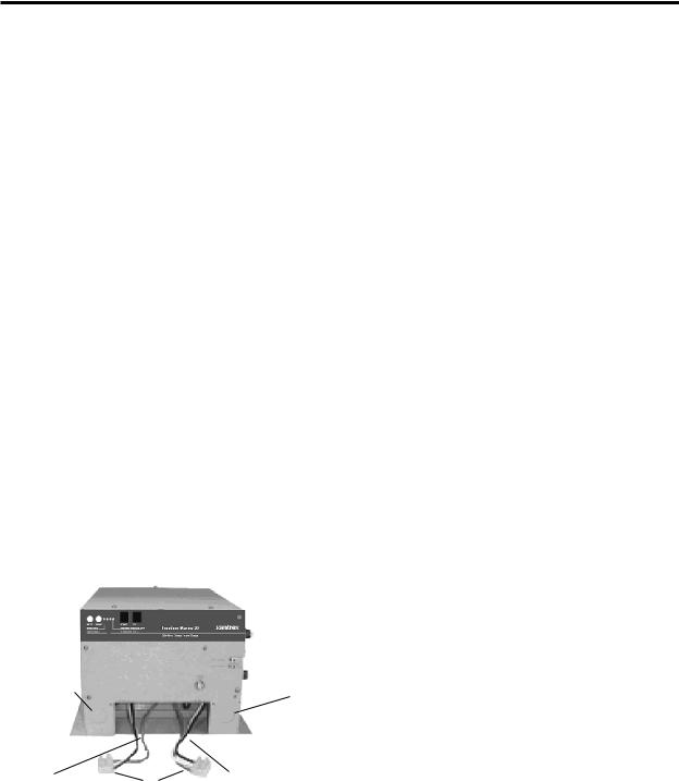
Thermostat Controlled Cooling
Freedom Inverter/Chargers are equipped with a thermostatically controlled fan that cools the unit so it can operate continually at its rated output.
KNOCKOUT |
KNOCKOUT |
|
AC OUTPUT
AC INPUT COMPRESSION TERMINAL
BLOCK installed
Inverter Idle Circuit
The idle circuit reduces battery power consumption when no AC load is present. Response from idle is instantaneous. When using a Freedom or Link remote control panel the idle threshold is adjustable. The unit does not produce 120 volts when in idle. An idle pulse is sent out approximately twice a second to see if a load is present. To bring the unit out of the idle condition, apply a load larger than the idle set point.
Low and High Battery Shutdown
When in inverter mode, if the battery voltage drops to 10.0 volts, the inverter will automatically shut off. Charge the batteries to 13.5 volts to automatically resume operation.
Voltage shutdown also occurs for a high battery condition at 15.5 volts. Operation will resume automatically when the battery voltage drops below 15.5 volts. Check all DC sources on the system for the reason for the excessive voltage.
Power Sharing
When connected to an external AC source the battery charger and transfer functions are engaged. A unique Power Sharing feature automatically reduces the AC power consumption of the battery charger when the loads threaten to trip the incoming circuit breaker.
Freedom 25 and 30 have two AC inputs. The battery charger is supplied AC from AC input #1. These models will reduce the current available to the charger when the demand for current to the load on AC output #1 reaches the factory default setting. AC input #2 is a direct transfer to AC output #2 and has no power sharing control.
6
THINGS YOU SHOULD KNOW
The Power Sharing set point of each unit has a factory default setting. This can be changed when using the Freedom or Link remote control panel. Refer to the Freedom Remote Control Panel or Link manual for information on Power Sharing setting and adjustment.
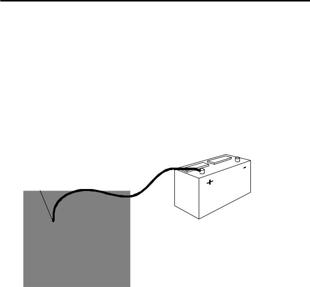
Temperature Sensitive Charging (TSC)
When the supplied battery temperature sensor is connected to the unit and the batteries, the charge voltage is controlled based on battery temperature. The charger adjusts the charge voltage to the best level insuring safe charging for selected battery type. Charge voltage regulation optimizes the battery life cycle.
Electronic Protection
Fast-acting electronic circuits protect the inverter from overloads and short circuits. Other protection includes a low and high battery voltage cutoff and automatic shutdown if an over temperature condition occurs. When the fault condition is corrected, the unit will automatically reset. For example: remove overload, charge batteries or allow to cool.
TSC Sensor
Battery
7
OPERATION
The Freedom Inverter/Charger provides 120 volt AC power from auxiliary DC batteries, automatic battery charging and automatic AC transfer switching between an external AC source and inverter mode AC output.
The Freedom Inverter/Charger may be operated with or without a remote control panel or Link instrument.
When operating the inverter/charger without a Freedom or Link remote control panel:
Front Panel Controls and Indicators
INVERT MODE
The INVERT push-button switch is located on the front of the unit.
• To turn the inverter ON, press and hold the INVERT switch until the INVERT LED is solid green. The unit is now inverting. Press the INVERT switch again to turn the inverter OFF. Note: The charge LED will be blinking slowly indicating Charger ready status but external AC power is not connected.
CHARGE MODE
The CHARGE push-button switch is located on the front of the unit.
When external AC is applied to the AC input of the unit, the charger automatically turns ON. The CHARGE LED will be solid green. The unit is now charging. Press the CHARGE switch again to turn the charger OFF. The charger defaults to ON when operating without a remote or with the Freedom Remote Control Panel. Refer to the Link manual when using a Link remote control panel.
INVERT
CHARGE
STATUS LEDs
Each Status LED performs two functions, providing operation status and battery type selection.
|
Status LEDs |
|
Front Panel |
INVERT CHARGE |
REMOTE TSC |
INVERT/WET |
OVERTEMP |
|
OVERLOAD / AGM |
CHARGE / GEL1 |
LOW BATTERY / GEL 2 |
Operation Status
INVERT - Green LED
•When the LED is solid green, the unit is in invert mode. This occurs by pressing the INVERT switch.
•When the LED is blinking slowly (1 time per second), the inverter is in standby with AC power applied and the transfer switch engaged
•When the LED is OFF, the inverter is
OFF.
CHARGE - Green LED
•When the LED is solid green, the unit is in the charge mode and external AC power is being supplied.
•When the LED is blinking slowly, (1 time per second) the charger is ready, but external AC power is not available.
•When the LED is OFF, the charger has been manually turned OFF. This can only be accomplished while AC power is being supplied since the charger will automatically restart each time AC power is applied.
8 |
Freedom Marine 20 |
OPERATION
NOTE: When AC power is available, the default setting for the charger is ON. If the unit was manually turned OFF and AC power is interrupted and becomes available again, the charger will return to ON.
LOW BATTERY - Red LED
•When the LED is OFF the battery voltage is normal, between 10.5 and 15.0 volts DC.
•When the LED is solid red, it indicates a battery warning condition, the battery voltage is below 10.5 volts DC or above 15.0 volts DC.
•When the LED is blinking slowly, (once per second), a battery shutdown has occurred. The voltage is either below 10.0 volts DC or above 15.5 volts DC.
•When the LED is blinking rapidly (five times per second), a potential problem in the DC system has been detected. Check your batteries, battery cables and DC loads.
OVER-TEMP/OVERLOAD - Red LED
•When the LED is Off operation is normal.
•When the LED is red, there is an overtemp or overload condition. Check for excessive loads or short circuit on the output of the inverter. Correct the condition and restart by pushing the INVERT switch.
•When the LED is blinking slowly (once per second), an over-current condition or a short circuit has occurred. The system has shut OFF and will not automatically restart. Correct the fault condition and manually restart the system by pushing the INVERT switch.
LOW BATTERY & OVER-TEMP/OVERLOAD
- Red LEDs
When both LEDs are blinking, an AC backfeed was detected. A backfeed occurs
when AC power from an external source is connected to the output of the inverter. Inspect wiring for a possible input/output wiring error. This condition must be corrected before further operation. A backfeed will damage the unit and void the warranty.
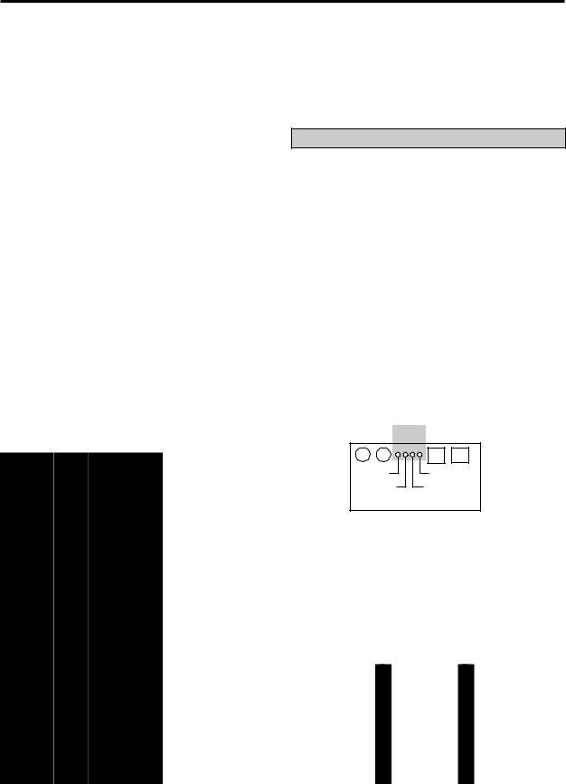
Battery Type Selection
• Battery type setup. To enter the battery type select mode, press and hold the INVERT switch for five seconds. The status LEDs will change from indicating status information to OFF. Press the CHARGE switch once. One of the four LEDs will blink rapidly, indicating the existing battery type selection.
Press the CHARGE switch again to change the battery type. Continue to press until the desired battery type is selected. If the CHARGE switch is not pressed for five seconds, the unit will return to normal operation and the battery type selection will have been made. Refer to page 20 for additional information on battery type settings.
WET GEL 1 |
GEL 2 AGM |
Status LEDs |
|
INVERT CHARGE |
REMOTE TSC |
INVERT/WET |
OVERTEMP |
|
OVERLOAD / AGM |
CHARGE / GEL1 |
LOW BATTERY / GEL 2 |
Front Panel
When the 12 volt input to the unit is disconnected, the battery type setting is stored in non-volatile memory. When the unit is reconnected, the battery type selection conveniently returns to the previous setting.
If installed with the Freedom or Link remote control panel, the unit will be set up and controlled from the remote. Refer to the remote manual for more information.
9

OPERATION
When a Freedom or Link remote control panel is connected to the unit, the switch on the unit or on the remote may be used to turn the unit ON/OFF. If the unit is turned ON using the front panel switch and then turned OFF using a Remote or Link, the unit will not be completely OFF. If the unit will not be used for an extended period of time, turn the unit completely OFF. The unit is completely OFF when the LED display on the unit is OFF.
TSC (Temperature Sensitive Charging)
This provides for the connection of a sensor to measure battery temperature for compensated charging. If no sensor is connected the charge voltage levels are set to defaults based on battery type.
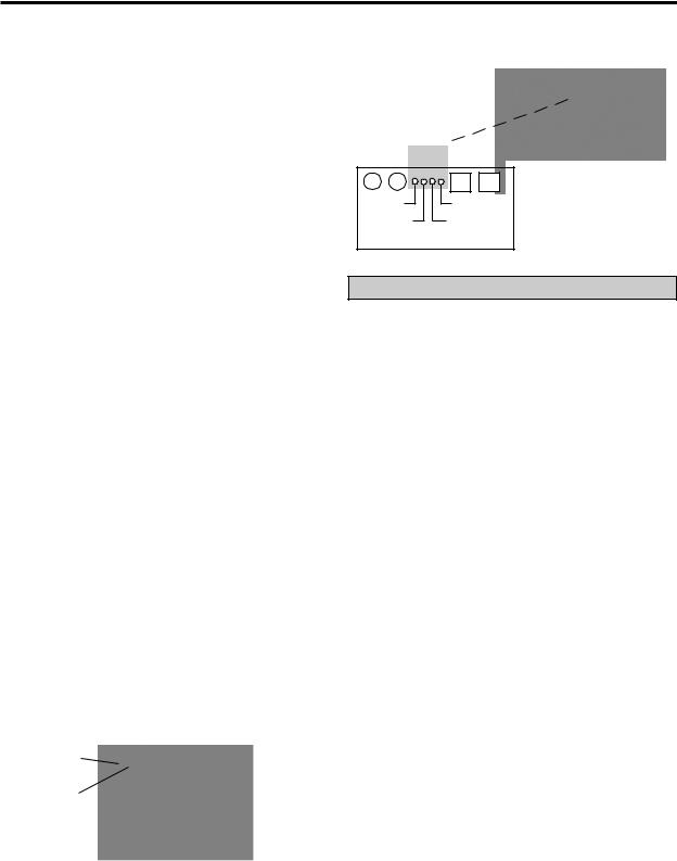
echo-charge
The echo-charge feature is incorporated in the Freedom Marine Inverter/Charger to enable multiple battery bank charging of the start or auxiliary battery. Freedom 10, 15, 20 have one active echo-charge output. Freedom 25, 30 have two active outputs.
The echo-charge automatically switches On/Off, charging an auxiliary or start battery without affecting the main house battery bank. The maximum charge current is 15 amps at
14.4volts.
The echo-charge is a voltage follower, fol-
lowing the three-stage charge modes of the Freedom Marine Charger. The echo-charge senses if the start battery needs charging and diverts a portion of the charging current (up to 15 amps) to the start battery. This method pro-
tects the auxiliary battery from overcharging and ensures a long life for the battery.
|
Over-temp |
Low |
Remote TSC |
Battery
echo-charge
Freedom Marine 20
NOTE: The charger will always follow the house battery setting, even if you mix the type of batteries in your house and start battery bank. If the house battery bank is either GEL or AGM and the start or auxiliary battery is wet/ flooded, the charger will follow the GEL or AGM voltage setting.
The echo-charge will turn ON any time the house battery is above 13 volts, regardless of the charging source.
OPTIONAL REMOTES
If using one of the remotes, refer to the installation instructions included with the remote.
10

OPTIONAL REMOTE CONTROL PANELS
Remote Control Panel
An optional remote control panel is available. The LED bar graphs on the remote control panel show battery voltage and DC current in both inverter and charger modes.
Easy-to-see red, yellow and green LEDs show the battery state-of-charge. Power Sharing, charger ON/OFF, and inverter ON/ OFF controls are provided. SET UP features include selection of Idle Threshold, Battery Type and Battery Capacity.
LINK 2000
The Link 2000 has the same features as the Link 1000, providing inverter/charger control and complete battery state-of-charge information. It monitors two battery banks.
LINK 2000
Remote Control Panel
Advanced Remote Control Panels Link Instruments
Advanced remote control panels are also available: the Link 1000, 2000 and 2000-R.
LINK 1000
Link 1000 controls the Freedom Inverter/ Charger and provides complete battery state-of-charge information including DC voltage, current, amp hours consumed, Time Remaining and historical data for a single battery bank.
LINK 2000-R
The Link 2000-R adds the ability to regulate an engine-driven alternator. The precision regulator in the Link 2000-R allows the alternator to be controlled as a three-stage battery charging system.
If a Link Instrument is used to control the inverter/charger, refer to the Link Owner’s Manual for installation, setup and control information.
LINK 1000
11

BATTERIES
BATTERY TYPES
Use only deep-cycle batteries with your Freedom Inverter/Charger. These fall into three broad categories: wet cell, gel cell and Advanced AGM (Absorbed Glass Mat) batteries.
Wet Cell Batteries
True deep-cycle wet cell batteries are characterized by relatively thick internal plates that are alloyed with antimony.
Common 12 volt marine/RV deep-cycle batteries are acceptable. Golf cart batteries perform well and may have a longer life. These 6 volt batteries must be used in series connected pairs. High quality deep-cycle batteries offer good performance and are available in a wide variety of sizes.
Wet cell batteries will give off gas as a natural result of charging and will experience some water loss. It is very important that the electrolyte level be checked frequently and topped off with distilled water when necessary. Follow the battery manufacturer’s recommendations for maintenance.
Never allow the top of the battery plates to be exposed to air, as contamination of the cell will result. Keep the tops of batteries clean.
Always provide adequate ventilation for the battery storage compartment.
Do not use ordinary car batteries or engine starting batteries with your inverter/ charger. Beware of any battery that is rated only in Cold Cranking Amps (CCA). This is a rating which applies only to engine starting batteries. In general, most wet cell batteries that are described as hybrid type batteries, suitable for either engine starting or deep-cycle applications, are a compromise and will have limited life if deeply discharged.
12
BATTERIES
Beware of so-called maintenance-free wet cell batteries. These batteries have calcium alloyed with the lead liquid. They are sealed and water cannot be added. Do not confuse them with true gel cell or AGM batteries—they will not hold up well to deep discharging and repeated cycling.
Gel Cell Batteries
Gel cell batteries are lead-acid batteries similar in many ways to the common wet cell battery, but differences in the chemistry and construction provide some unique features.
•No Maintenance
•Low Self-Discharge Rate
•Low Internal Resistance
Even though gel cells are sealed batteries, the battery compartment should still be ventilated.
Advanced AGM (Absorbed Glass Mat) Batteries
This battery is lead acid but maintenance free. They hold the liquid electrolyte in a sponge-like material. The performance is similar to gel cell batteries. The charge parameters are similar to wet cell batteries.
Battery Selection
The most important feature to consider in making your battery selection is to select true deep cycle batteries rated in amp hours (Ah) and sized to match your power requirements.
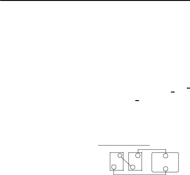
BATTERY INTERCONNECTION
In most cases, you will be using a bank of two or more batteries with your inverter/charger. You may connect batteries together in two configurations—series and parallel— depending on their voltage.
Series Configuration
Connecting two batteries in series will double the voltage of the battery bank. For instance, two 6 volt batteries connected in series will produce 12 volts. The amp-hour capacity of the battery bank will be the same as each individual battery. Example, two 6 volt 220 amp-hour batteries in series will produce one 12 volt 220 amp-hour battery bank.
++
Series
Series Increase Voltage
+ |
+ |
+ |
6V |
6V |
12V INVERTER |
_ |
_ |
_ |
|
|
|
EACH BATTERY |
|
TOTAL BATTERY |
CAPACITY: |
|
BANK CAPACITY: |
220 |
|
220 |
AMP HOURS |
|
AMP HOURS |
@ 6 VDC |
|
@ 12 VDC |
13
BATTERIES
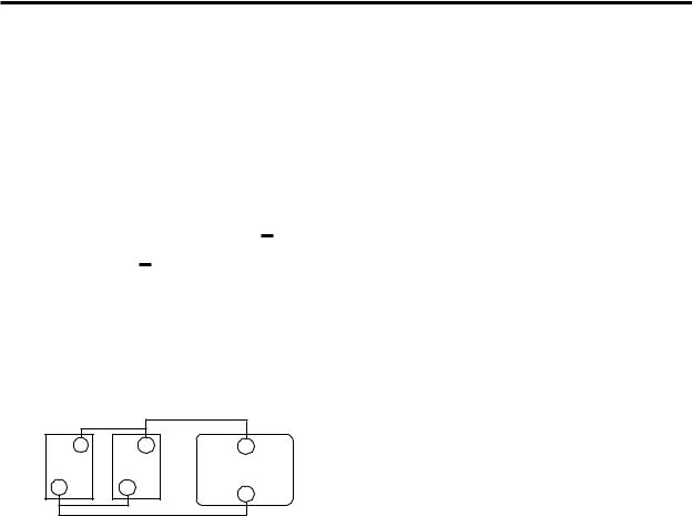
Parallel Configuration
Connecting two batteries in parallel will double the amp-hour rating of the battery bank, while the voltage will be the same as each individual battery. Example, two 12 volt 105 amp-hour batteries in parallel will produce one 12 volt 210 amp-hour battery bank.
+
+
Parallel
Parallel Increase Amp-hour Capacity
+ |
+ |
+ |
|
12V |
12V |
12VINVERTER |
|
_ |
_ |
||
_ |
|||
|
|
||
EACH BATTERY |
|
TOTAL BATTERY |
|
CAPACITY: |
|
BANK CAPACITY: |
|
105 |
|
210 |
|
AMP HOURS |
|
AMP HOURS |
|
@ 12 VDC |
|
@ 12 VDC |
Only similar batteries should be connected together in one bank. Do not connect old and new batteries together or wet and gel cell batteries together. In the above drawing, the load is connected to the positive terminal of the first battery and the negative terminal of the last battery. This practice helps to balance the battery bank and is called cross-connecting the battery bank.
Note: It is not advisable to connect batteries of different case sizes or amp-hour ratings in the same battery bank.
Always use properly sized wire and terminals for your interconnecting battery cables. For size information refer to NEC requirements or contact your local electrician.
BATTERY BANK RATINGS AND SIZING
Deep-cycle batteries are usually rated in amp hours. The amp-hour rating is based on a 20-hour discharge rate, therefore, a 100 amp-hour battery can deliver 5 amps for 20 hours. If the discharge rate is greater than 5 amps, the available amp hours are decreased. For example, if the load is increased to 100 amps, only about 45 amp hours will be available at this rate of discharge.
Deep-cycle batteries can be discharged about 80% of capacity before damage occurs. Shallow cycling will result in much longer battery life. Calculating a battery bank size based on 50% discharge cycling is generally considered to be a good compromise between long battery life and size.
14
|
|
|
|
|
|
|
|
|
|
|
|
|
|
|
|
BATTERIES |
|
|
|
|
|
|
|
|
|
|
|
|
|
|
|
|
|
||
To achieve 50% cycling you should |
|
|
|
|
AMP-HOUR CONSUMPTION FORMULAS |
||||||||||||
calculate your amp-hour consumption |
|
|
|
|
|
|
|
|
|
|
|
|
|||||
|
|
|
|
|
|
|
(AC amps x 10) x 1.1 x hours of |
|
|||||||||
between charging cycles and use a battery |
|
|
|
|
|||||||||||||
bank with twice that capacity**. Each AC |
|
|
|
|
|
operation = DC amp hours |
|
||||||||||
appliance or tool has a rating plate on it and will |
|
|
|
(watts/ DC voltage) x 1.1 x hours of |
|
||||||||||||
be rated in either AC amps or watts or AC VA |
|
|
|
|
|||||||||||||
|
|
|
operation = DC amp hours |
|
|||||||||||||
(volt-amps) apparent power. To calculate amp- |
|
|
|
|
|||||||||||||
|
|
|
(AC VA/ DC voltage) x 1.1 x hours of |
|
|||||||||||||
hour consumption, use one of the formulas to |
|
|
|
|
|||||||||||||
the right to calculate the DC amp-hour draw for |
|
|
|
operation = DC amp hours |
|
||||||||||||
a 12 volt system. |
|
|
|
|
|
|
|
|
|
|
|
DC voltage is 12, 24 or 32 depending on |
|
||||
|
|
|
|
|
|
|
|
|
|
|
|
|
|
||||
Calculate the amp hours for every AC |
|
|
|
|
|
|
|
|
your system. |
|
|||||||
appliance or tool that will be operated on the |
|
|
|
|
|
|
|
|
|||||||||
|
|
|
|
|
|
|
|
||||||||||
inverter. This will provide the total number of |
|
|
In all formulas, 1.1 is the correction factor for |
||||||||||||||
amp hours used between recharges. Size the |
|
|
|
|
|
|
inverter efficiency. |
||||||||||
battery bank using this number as a guideline. |
|
Typical Power Consumptlon |
|||||||||||||||
A good rule to follow is to size the battery bank |
|
||||||||||||||||
a minimum of two times larger than the |
|
|
|
|
|
The chart identifies typical power |
|||||||||||
total amp-hour load requirement. Plan on |
|
|
|
consumption for common AC loads. Use it as |
|||||||||||||
recharging when 50% discharged. |
|
|
|
|
|
a guide when identifying your power |
|||||||||||
**Batteries are typically charged to 85% of full |
|
requirements. |
|
|
|||||||||||||
|
|
|
|
|
|
Many electric motors have |
|||||||||||
charge when charging with alternators without 3-stage |
|
|
|
|
|
|
|||||||||||
regulators. |
|
|
|
|
|
|
|
|
|
|
|
|
|
|
|
momentary starting requirements |
|
|
|
|
|
|
|
|
|
|
|
|
|
|
|
|
|
||
|
|
|
|
|
|
|
|
|
|
|
|
|
|
|
|
well above their operational rating. |
|
|
Typical Power Consumption |
|
|
|
|
|
|
|
|
||||||||
|
|
|
|
|
|
|
|
|
Start up watts are listed where |
||||||||
|
|
|
|
|
|
|
|
|
|
|
|
|
|
|
|
||
Appliance |
Typical |
|
|
Appliance Run Times / Amp Hours |
|
|
|
|
appropriate. Individual styles and |
||||||||
Wattage |
|
|
|
|
|
|
|
|
|
|
|
|
|
brands of appliances may vary. |
|||
|
5 Min. |
15 Min. |
30 Min. |
|
1 Hr. |
|
2 Hr. |
|
3 Hr. |
|
8 Hr. |
24 Hr. |
|||||
|
|
|
|
|
|
|
|
|
|
|
|
|
|
|
|
|
|
|
|
|
|
|
|
|
|
|
|
|
|
|
|
|
|
If using the same battery |
|
13" Color TV |
50 |
.33 |
1 |
2 |
|
4 |
|
8 |
|
12 |
|
|
32 |
96 |
|
||
|
|
|
|
|
|
|
|
||||||||||
|
|
|
|
|
|
|
|
|
|
|
|
|
|
|
|
bank for the inverter and other |
|
19" Color TV |
100 |
.66 |
2 |
4 |
|
8 |
|
16 |
|
24 |
|
|
64 |
192 |
|
||
|
|
|
|
|
|
|
|
||||||||||
|
|
|
|
|
|
|
|
|
|
|
|
|
|
|
|
DC loads, be sure to consider |
|
VCR |
50 |
.33 |
1 |
2 |
|
4 |
|
8 |
|
12 |
|
|
32 |
96 |
|
||
|
|
|
|
|
|
|
|
||||||||||
|
|
|
|
|
|
|
|
|
|
|
|
|
|
|
|
the power consumption of the |
|
Lamp |
100 |
.66 |
2 |
4 |
|
8 |
|
16 |
|
24 |
|
|
64 |
192 |
|
||
|
|
|
|
|
|
|
|
||||||||||
|
|
|
|
|
|
|
|
|
|
|
|
|
|
|
|
DC loads when sizing the |
|
Blender |
300 |
2 |
6 |
12 |
|
|
|
|
|
|
|
|
|
|
|
||
|
|
|
|
|
|
|
|
|
|
|
|
|
|
|
|
battery bank. |
|
Laptop Computer |
50 |
.33 |
1 |
2 |
|
4 |
|
8 |
|
|
|
|
|
|
|
||
Curling Iron |
50 |
.33 |
1 |
2 |
|
|
|
|
|
|
|
|
|
|
|
|
|
|
|
|
|
|
|
|
|
|
|
|
|
|
|
|
|
|
|
3/8 Power Drill |
500 |
3.3 |
10 |
20 |
|
|
|
|
|
|
|
|
|
|
|
|
|
|
|
|
|
|
|
|
|
|
|
|
|
|
|
|
|
|
|
Icemaker* |
200 |
|
|
2.6 |
|
5.2 |
|
10.4 |
|
15.6 |
|
41.6 |
83.2 |
|
|
|
|
|
|
|
|
|
|
|
|
|
|
|
|
|
|
|
|
|
|
Coffee Maker |
1000 |
6.6 |
20 |
40 |
|
80 |
|
160 |
|
|
|
|
|
|
|
|
|
|
|
|
|
|
|
|
|
|
|
|
|
|
|
|
|
|
|
3 cu' Refrigerator* |
150 |
|
|
2 |
|
4 |
|
8 |
|
12 |
|
|
32 |
96 |
|
|
|
|
|
|
|
|
|
|
|
|
|
|
|
|
|
|
|
|
|
20 cu' Refrigerator* |
750 |
|
|
21 |
|
42 |
|
84 |
|
126 |
|
336 |
672 |
|
|
|
|
|
|
|
|
|
|
|
|
|
|
|
|
|
|
|
|
|
|
Compact Microwave |
750 |
5 |
15 |
30 |
|
60 |
|
120 |
|
180 |
|
|
|
|
|
|
|
|
|
|
|
|
|
|
|
|
|
|
|
|
|
|
|
|
|
Full Size Microwave |
1500 |
10 |
30 |
60 |
|
120 |
|
240 |
|
360 |
|
|
|
|
NOTE Certain laser printers, breadmakers, |
||
|
|
|
|
|
|
|
|
|
|
|
|
|
|
|
|
||
|
|
|
|
|
|
|
|
|
|
|
|
|
|
|
|
||
Vacuum |
1100 |
7.3 |
22 |
44 |
|
88 |
|
176 |
|
264 |
|
|
|
|
digital clocks and appliance/tool chargers |
||
|
|
|
|
|
|
|
|
|
|
|
|
|
|
|
|
||
Number in each box represents the total Amp hours used (@ 12 volt DC) based on various continuous run times. *Note refrigeration is typically calculated using a 1/3-duty cyle.
may not operate on modified sine wave.
15
 Loading...