


XHR
Table of contents
 Loading...
Operating Manual
Internal GPIB Interface
for XHR/XFR Series
Programmable DC
Power Supplies
GPIB-XHR
GPIB-XFR
GPIB-XFR3


Operating Manual for
Internal GPIB Interface
for XHR 1000 Watt Series,
XFR 1200 Watt Series and
XFR 2800 Watt Series
Programmable DC
Power Supplies

ii Operating Manual for GPIB for XHR/XFR Series Power Supply
Limited
Warranty
What does this warranty cover and how long does it last?
This Limited Warranty is provided by Xantrex Technology, Inc. (“Xantrex”) and
covers defects in workmanship and materials in your GPIB Interface Card. This
warranty lasts for a Warranty Period of 5 years from the date of purchase at point of
sale to you, the original end user customer.
What will Xantrex do?
Xantrex will, at its option, repair or replace the defective product free of charge,
provided that you notify Xantrex of the product defect within the Warranty Period,
and provided that Xantrex through inspection establishes the existence of such a
defect and that it is covered by this Limited Warranty.
Xantrex will, at its option, use new and/or reconditioned parts in performing
warranty repair and building replacement products. Xantrex reserves the right to use
parts or products of original or improved design in the repair or replacement. If
Xantrex repairs or replaces a product, its warranty continues for the remaining
portion of the original Warranty Period or 90 days from the date of the return
shipment to the customer, whichever is greater. All replaced products and all parts
removed from repaired products become the property of Xantrex.
Xantrex covers both parts and labor necessary to repair the product, and return
shipment to the customer via a Xantrex-selected non-expedited surface freight
within the contiguous United States and Canada. Alaska and Hawaii are excluded.
Contact Xantrex Customer Service for details on freight policy for return shipments
outside of the contiguous United States and Canada.
How do you get service?
If your product requires troubleshooting or warranty service, contact your merchant.
If you are unable to contact your merchant, or the merchant is unable to provide
service, contact Xantrex directly at:
Phone: 604 422 8595
Toll Free North America: 1 800 667 8422
Fax: 604 421 3056
Email: info@xantrex.com

Release 3.1 iii
Direct returns may be performed according to the Xantrex Return Material
Authorization Policy described in your product manual. For some products, Xantrex
maintains a network of regional Authorized Service Centers. Call Xantrex or check
our website to see if your product can be repaired at one of these facilities.
In any warranty claim, dated proof of purchase must accompany the product and the
product must not have been disassembled or modified without prior written
authorization by Xantrex.
Proof of purchase may be in any one of the following forms:
• The dated purchase receipt from the original purchase of the product at point of
sale to the end user, or
• The dated dealer invoice or purchase receipt showing original equipment
manufacturer (OEM) status, or
• The dated invoice or purchase receipt showing the product exchanged under
warranty
What does this warranty not cover?
This Limited Warranty does not cover normal wear and tear of the product or costs
related to the removal, installation, or troubleshooting of the customer’s electrical
systems. This warranty does not apply to and Xantrex will not be responsible for any
defect in or damage to:
a. the product if it has been misused, neglected, improperly installed, physically
damaged or altered, either internally or externally, or damaged from improper
use or use in an unsuitable environment;
b. the product if it has been subjected to fire, water, generalized corrosion,
biological infestations, and high input voltage from lightning strikes;
c. the product if repairs have been done to it other than by Xantrex or its authorized
service centers (hereafter “ASCs”);
d. the product if it is used as a component part of a product expressly warranted by
another manufacturer;
e. the product if its original identification (trade-mark, serial number) markings
have been defaced, altered, or removed.

iv Operating Manual for GPIB for XHR/XFR Series Power Supply
Disclaimer Product
THIS LIMITED WARRANTY IS THE SOLE AND EXCLUSIVE WARRANTY PROVIDED
BY XANTREX IN CONNECTION WITH YOUR XANTREX PRODUCT AND IS, WHERE
PERMITTED BY LAW, IN LIEU OF ALL OTHER WARRANTIES, CONDITIONS,
GUARANTEES, REPRESENTATIONS, OBLIGATIONS AND LIABILITIES, EXPRESS
OR IMPLIED, STATUTORY OR OTHERWISE IN CONNECTION WITH THE PRODUCT,
HOWEVER ARISING (WHETHER BY CONTRACT, TORT, NEGLIGENCE, PRINCIPLES
OF MANUFACTURER’S LIABILITY, OPERATION OF LAW, CONDUCT, STATEMENT
OR OTHERWISE), INCLUDING WITHOUT RESTRICTION ANY IMPLIED WARRANTY
OR CONDITION OF QUALITY, MERCHANTABILITY OR FITNESS FOR A
PARTICULAR PURPOSE. ANY IMPLIED WARRANTY OF MERCHANTABILITY OR
FITNESS FOR A PARTICULAR PURPOSE TO THE EXTENT REQUIRED UNDER
APPLICABLE LAW TO APPLY TO THE PRODUCT SHALL BE LIMITED IN DURATION
TO THE PERIOD STIPULATED UNDER THIS LIMITED WARRANTY.
IN NO EVENT WILL XANTREX BE LIABLE FOR ANY SPECIAL, DIRECT, INDIRECT,
INCIDENTAL OR CONSEQUENTIAL DAMAGES, LOSSES, COSTS OR EXPENSES
HOWEVER ARISING WHETHER IN CONTRACT OR TORT INCLUDING WITHOUT
RESTRICTION ANY ECONOMIC LOSSES OF ANY KIND, ANY LOSS OR DAMAGE TO
PROPERTY, ANY PERSONAL INJURY, ANY DAMAGE OR INJURY ARISING FROM OR
AS A RESULT OF MISUSE OR ABUSE, OR THE INCORRECT INSTALLATION,
INTEGRATION OR OPERATION OF THE PRODUCT.
Exclusions If this product is a consumer product, federal law does not allow an exclusion of
implied warranties. To the extent you are entitled to implied warranties under federal
law, to the extent permitted by applicable law they are limited to the duration of this
Limited Warranty. Some states and provinces do not allow limitations or exclusions
on implied warranties or on the duration of an implied warranty or on the limitation
or exclusion of incidental or consequential damages, so the above limitation(s) or
exclusion(s) may not apply to you. This Limited Warranty gives you specific legal
rights. You may have other rights which may vary from state to state or province to
province.

Release 3.1 v
Information WITHOUT LIMITING THE GENERALITY OF THE FOREGOING, UNLESS
SPECIFICALLY AGREED TO BY IT IN WRITING, XANTREX
a. MAKES NO WARRANTY AS TO THE ACCURACY, SUFFICIENCY OR SUITABILITY
OF ANY TECHNICAL OR OTHER INFORMATION PROVIDED IN MANUALS OR
OTHER DOCUMENTATION PROVIDED BY IT IN CONNECTION WITH THE
PRODUCT; AND
b. ASSUMES NO RESPONSIBILITY OR LIABILITY FOR LOSSES, DAMAGES,
COSTS OR EXPENSES, WHETHER SPECIAL, DIRECT, INDIRECT,
CONSEQUENTIAL OR INCIDENTAL, WHICH MIGHT ARISE OUT OF THE USE OF
SUCH INFORMATION.
THE USE OF ANY SUCH INFORMATION WILL BE ENTIRELY AT THE USER’S RISK.
WARNING:
Limitations
on Use
Please refer to your product user manual for limitations on uses of the product.
Specifically, please note that this power supply is not intended for use in connection
with life support systems and Xantrex makes no warranty or representation in
connection with any use of the product for such purposes.
Xantrex Technology, Inc.
8999 Nelson Way
Burnaby, British Columbia
Canada V5A 4B5
Information
About Your
Power
Supply
Please record the following information when you first open your Power Supply
package:
Release Release 3.1 (2002-06)
Copyright
©
2002 Xantrex Technology Inc. All rights reserved.
Printed in Canada
Model Number ______________________________________________
Serial Number ______________________________________________
Purchased From ______________________________________________
Purchase Date ______________________________________________
vi Operating Manual for GPIB for XHR/XFR Series Power Supply
Power
Supply
Safety
Warnings,
Cautions,
and Notes
Warnings, cautions, and notes are defined and formatted in this manual as shown
below.
WARNING—High Energy and High Voltage
Exercise caution when using and calibrating a power supply. High energy levels
can be stored at the output voltage terminals on a power supply in normal
operation. In addition, potentially lethal voltages exist in the power circuit and on
the output and sense connectors of a power supply with a rated output greater
than 40 V. Filter capacitors store potentially dangerous energy for some time after
power is removed.
!
CAUTION
Operate the power supply in an environment free of flammable gases or fumes.
To ensure that the power supply’s safety features are not compromised, use the
power supply as specified in this manual and do not substitute parts or make any
unauthorized modifications. Contact the service technician for service and repair
help. Repairs must be made by experienced service technicians only.
WARNING
Describes a potential hazard which could result in injury or death, or, a procedure
which, if not performed correctly, could result in injury or death.
!
CAUTION
Describes a procedure which, if not performed correctly, could result in damage
to data, equipment, or systems.
Note
Describes additional operating information which may affect the performance of the
equipment.

Release 3.1 vii
About This Manual
This technical manual is for the internal GPIB interface, a microprocessor-controlled
option card for XHR Series and XFR Series DC output power supplies. This manual
provides you with descriptions and specifications, user options, and configuration
instructions, in addition to a command set which enables you to manage the power
supply from an external source. Error messages and calibration procedures are also
included.
This manual is designed for the user who is familiar with basic electrical theory
especially as it applies to the operation of power supplies. This implies a recognition
of Constant Voltage and Constant Current operation modes and the control of input
and output power, as well as the observance of safe techniques while effecting supply
or pin connections and any changes in switch settings. The user should also have
experience with a computer-based communications software package.
Refer to your power supply manual for installation, configuration, and operating
procedures for your power supply.
Main Sections
Section 1 Features and Specifications Describes the power supply and lists
its features and specifications.
Section 2 Installation and Configuration Goes through basic setup
procedures. Describes inspection, cleaning, shipping, and storage procedures.
Includes additional options for configuring the GPIB interface for operation.
Section 3 Operation Lists the complete command set, status registers, and error
codes.
Section 4 Calibration Provides detailed procedures for voltage and current
mode calibration as well as over voltage protection (OVP) calibration. Includes
calibration for programming and readback accuracy.
Manual Revisions
The current release of this manual is listed below. Updates may be issued as an
addendum.
Release 3.1 (2002/06)

About This Manual
viii Operating Manual for GPIB for XHR/XFR Series Power Supply

Release 3.1 ix
Contents
About This Manual . . . . . . . . . . . . . . . . . . . . . . . . . . . . . . . . . . . . . . . . . . . . . . . . . . . vii
Section 1.
Features and
Specifications
Description . . . . . . . . . . . . . . . . . . . . . . . . . . . . . . . . . . . . . . . . . . . . . . . . . . . . . . . . . 11
Features and Functions . . . . . . . . . . . . . . . . . . . . . . . . . . . . . . . . . . . . . . . . . . . . . . . 12
Features. . . . . . . . . . . . . . . . . . . . . . . . . . . . . . . . . . . . . . . . . . . . . . . . . . . . . . . 12
Programmable Functions. . . . . . . . . . . . . . . . . . . . . . . . . . . . . . . . . . . . . . . . . . 12
Readback Functions . . . . . . . . . . . . . . . . . . . . . . . . . . . . . . . . . . . . . . . . . . . . . 12
Specifications . . . . . . . . . . . . . . . . . . . . . . . . . . . . . . . . . . . . . . . . . . . . . . . . . . . . . . . 13
Section 2.
Installation
and
Configuration
Introduction. . . . . . . . . . . . . . . . . . . . . . . . . . . . . . . . . . . . . . . . . . . . . . . . . . . . . . . . . 19
Initial Inspection . . . . . . . . . . . . . . . . . . . . . . . . . . . . . . . . . . . . . . . . . . . . . . . . . . . . . 19
Basic Setup Procedure. . . . . . . . . . . . . . . . . . . . . . . . . . . . . . . . . . . . . . . . . . . . . . . . 23
IEEE-488 Primary Address Selection. . . . . . . . . . . . . . . . . . . . . . . . . . . . . . . . . . . . . 24
Power On Service Request (PON SRQ) . . . . . . . . . . . . . . . . . . . . . . . . . . . . . . . . . . 25
Remote/Local Operation. . . . . . . . . . . . . . . . . . . . . . . . . . . . . . . . . . . . . . . . . . . . . . .25
Remote/Local Mode Startup . . . . . . . . . . . . . . . . . . . . . . . . . . . . . . . . . . . . . . .25
Remote Mode Operation . . . . . . . . . . . . . . . . . . . . . . . . . . . . . . . . . . . . . . . . . . 26
Local Mode Operation . . . . . . . . . . . . . . . . . . . . . . . . . . . . . . . . . . . . . . . . . . . . 27
Setting Local Lockout. . . . . . . . . . . . . . . . . . . . . . . . . . . . . . . . . . . . . . . . . . . . . 27
IEEE-488 Controller Connection. . . . . . . . . . . . . . . . . . . . . . . . . . . . . . . . . . . . . . . . . 28
Internal PCB Jumper Selections. . . . . . . . . . . . . . . . . . . . . . . . . . . . . . . . . . . . . . . . . 28
OVP Selection . . . . . . . . . . . . . . . . . . . . . . . . . . . . . . . . . . . . . . . . . . . . . . . . . . 28
TTL Shutdown . . . . . . . . . . . . . . . . . . . . . . . . . . . . . . . . . . . . . . . . . . . . . . . . . .29
User Signals . . . . . . . . . . . . . . . . . . . . . . . . . . . . . . . . . . . . . . . . . . . . . . . . . . . . . . . . 30
Connector J7 User Signals . . . . . . . . . . . . . . . . . . . . . . . . . . . . . . . . . . . . . . . . 30
J7 Cable Connection . . . . . . . . . . . . . . . . . . . . . . . . . . . . . . . . . . . . . . . . . . . . . 31
Section 3.
Operation
Introduction. . . . . . . . . . . . . . . . . . . . . . . . . . . . . . . . . . . . . . . . . . . . . . . . . . . . . . . . . 33
GPIB Operation . . . . . . . . . . . . . . . . . . . . . . . . . . . . . . . . . . . . . . . . . . . . . . . . . . . . . 33
Multiline Control Functions. . . . . . . . . . . . . . . . . . . . . . . . . . . . . . . . . . . . . . . . . 34
Device Clear. . . . . . . . . . . . . . . . . . . . . . . . . . . . . . . . . . . . . . . . . . . . . . . . . . . . 34
Device Trigger . . . . . . . . . . . . . . . . . . . . . . . . . . . . . . . . . . . . . . . . . . . . . . . . . .35
Parallel Poll . . . . . . . . . . . . . . . . . . . . . . . . . . . . . . . . . . . . . . . . . . . . . . . . . . . . 35
Local Lockout. . . . . . . . . . . . . . . . . . . . . . . . . . . . . . . . . . . . . . . . . . . . . . . . . . . 35
Service Request. . . . . . . . . . . . . . . . . . . . . . . . . . . . . . . . . . . . . . . . . . . . . . . . . 36
Serial Poll. . . . . . . . . . . . . . . . . . . . . . . . . . . . . . . . . . . . . . . . . . . . . . . . . . . . . . 36
Command Syntax . . . . . . . . . . . . . . . . . . . . . . . . . . . . . . . . . . . . . . . . . . . . . . . . . . . . 37
Manual Conventions . . . . . . . . . . . . . . . . . . . . . . . . . . . . . . . . . . . . . . . . . . . . . 37
Command Format and Parameters . . . . . . . . . . . . . . . . . . . . . . . . . . . . . . . . . . 37
Command Strings . . . . . . . . . . . . . . . . . . . . . . . . . . . . . . . . . . . . . . . . . . . . . . .39
Command Terminators . . . . . . . . . . . . . . . . . . . . . . . . . . . . . . . . . . . . . . . . . . . 39
Order . . . . . . . . . . . . . . . . . . . . . . . . . . . . . . . . . . . . . . . . . . . . . . . . . . . . . . . . . 39
Command Summary. . . . . . . . . . . . . . . . . . . . . . . . . . . . . . . . . . . . . . . . . . . . . . . . . .40

Contents
x
Operating Manual for GPIB for XHR/XFR Series Power Supply
Command Reference. . . . . . . . . . . . . . . . . . . . . . . . . . . . . . . . . . . . . . . . . . . . . . . . . 43
Accumulated Status, Status, and Fault Registers . . . . . . . . . . . . . . . . . . . . . . . . . . . 50
Error Codes . . . . . . . . . . . . . . . . . . . . . . . . . . . . . . . . . . . . . . . . . . . . . . . . . . . . . . . . 51
Troubleshooting . . . . . . . . . . . . . . . . . . . . . . . . . . . . . . . . . . . . . . . . . . . . . . . . . . . . . 52
Diagnostic LEDs . . . . . . . . . . . . . . . . . . . . . . . . . . . . . . . . . . . . . . . . . . . . . . . . 52
Section 4.
Calibration
Introduction . . . . . . . . . . . . . . . . . . . . . . . . . . . . . . . . . . . . . . . . . . . . . . . . . . . . . . . . 53
Voltage Mode Calibration. . . . . . . . . . . . . . . . . . . . . . . . . . . . . . . . . . . . . . . . . . . . . . 54
Voltage Calibration Setup . . . . . . . . . . . . . . . . . . . . . . . . . . . . . . . . . . . . . . . . . 54
Voltage Program Calibration Procedure . . . . . . . . . . . . . . . . . . . . . . . . . . . . . . 54
Voltage Readback Calibration Procedure . . . . . . . . . . . . . . . . . . . . . . . . . . . . . 54
Current Mode Calibration. . . . . . . . . . . . . . . . . . . . . . . . . . . . . . . . . . . . . . . . . . . . . . 56
Current Calibration Setup . . . . . . . . . . . . . . . . . . . . . . . . . . . . . . . . . . . . . . . . . 56
Current Program Calibration Procedure . . . . . . . . . . . . . . . . . . . . . . . . . . . . . . 56
Current Readback Calibration Procedure . . . . . . . . . . . . . . . . . . . . . . . . . . . . . 57
Over Voltage Protection (OVP) Calibration . . . . . . . . . . . . . . . . . . . . . . . . . . . . . . . . 58
Release 3.1 11
Section 1. Features and Specifications
Description
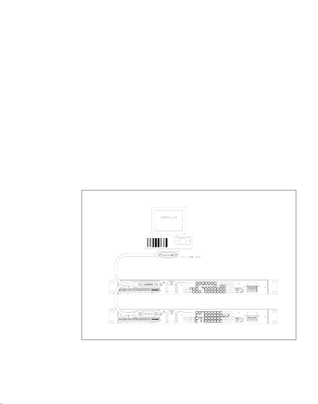
The internal GPIB interface card allows you to operate your power supply from a
computer controller via the IEEE-488 communications bus. See Figure 1.1, “Sample
Configuration using GPIB Interface”.
The GPIB interface allows complete remote programming of your power supply,
including status reporting, settings query, and interrupt generation with
user-designated fault conditions. Both the voltage and current output are precisely
programmed directly in volts and amps with 16-bit resolution. Additionally, the
built-in DVM and current shunt measure the actual power supply output and provide
you with 16-bit readback. The programming command set is easy-to-use and
includes software calibration commands. The interface card comes standard with
several protection features such as programmable over voltage protection, foldback,
load isolation signal, and soft limits.
Figure 1.1 Sample Configuration using GPIB Interface
(1200 Watt DC Power Supplies Shown)

Features and Specifications
Features and Functions
12 Operating Manual for GPIB for XHR/XFR Series Power Supply
Features and Functions
Features • 16-bit programming and readback of voltage and current
• Programmable soft limits for voltage and current
• Programmable over voltage protection with reset
• Easy-to-use, self-documenting command set
• Isolated user-programmable signals such as fault, polarity, isolation, and
auxiliary signals
• LED status signals: error, addressed, service request, over voltage protection,
and remote operation
• Foldback in CV or CC mode with reset
• Local Lockout capability
• Software calibration
Programmable
Functions
• Output voltage and current
• Soft limits for voltage and current
• Overvoltage protection
• Output enable/disable
• Maskable fault interrupt
• Hold and trigger
• User-programmable output relay signals
Readback
Functions
• Actual measured voltage and current
• Voltage and current settings
• Soft voltage and current limits
• Overvoltage protection setting
• Present and accumulated power supply status
• Programming error codes
• Fault codes
• Power supply model and version identification
• Firmware revision levels

Features and Specifications
Specifications
Release 3.1 13
Specifications
The specifications in this section are warranted at 25°C ±5°C unless otherwise
specified. All specifications are subject to change without notice.
Table 1. 1
Specifications for XFR 1200 W Series Supply with GPIB Interface Installed (7.5 V to 40 V)
Models 7.5-140 12-100 20-60 35-35 40-30
Program Resolution
Voltage
Current
OVP
1.16mV
19.6mA
1.16mV
1.8mV
14mA
1.8mV
3.08mV
8.4mA
3.08mV
5.4mV
5.4mA
5.4mV
6.2mV
4.2mA
6.2mV
Program Accuracy
1
Voltage
Current
OVP
1. Apply accuracy specifications according to the following voltage program accuracy example:
Set a model 20-60 power supply to 10 volts.
The expected result will be within the range of 10 volts ± 75mV ± 0.12% of the set voltage of 10 volts.
10mV
±0.12%
500mA
±0.1%
80mV
50mV
±0.12%
460mA
±0.1%
150mV
75mV
±0.12%
250mA
±0.1%
200mV
75mV
±0.3%
200mA
±0.1%
350mV
75mV
±0.3%
150mA
±0.15%
400mV
Readback Resolution
Voltage
Current
1.16mV
19.6mA
1.8mV
14mA
3.08mV
8.4mA
5.4mV
5.4mA
6.2mV
4.2mA
Readback Accuracy
1
Voltage
Current
30mV
±0.12%
500mA
±0.1%
60mV
±0.12%
460mA
±0.1%
75mV
±0.12%
250mA
±0.1%
75mV
±0.3%
200mA
±0.1%
75mV
±0.3%
150mA
±0.15%

Features and Specifications
Specifications
14 Operating Manual for GPIB for XHR/XFR Series Power Supply
Table 1. 2
Specifications for XFR 1200 W Series Supply with GPIB Interface Installed (60 V to 600 V)
Models 60-20 100-12 150-8 300-4 600-2
Program Resolution
Voltage
Current
OVP
9.2mV
2.8mA
9.2mV
15.4mV
1.68mA
15.4mV
23.1mV
1.12mA
23.1mV
46.2mV
0.56mA
46.2mV
92.4mV
0.28mA
92.4mV
Program Accuracy
1
Voltage
Current
OVP
1. Apply accuracy specifications according to the following voltage program accuracy example:
Set a model 20-60 power supply to 10 volts.
The expected result will be within the range of 10 volts ± 75mV ± 0.12% of the set voltage of 10 volts.
150mV
±0.25%
120mA
±0.1%
600mV
150mV
±0.35%
80mA
±0.1%
800mV
225mV
±0.35%
80mA
±0.1%
1.5V
225mV
±0.35%
80mA
±0.1%
3.0V
250mV
±0.35%
50mA
±0.1%
6V
Readback Resolution
Voltage
Current
9.2mV
2.8mA
15.4mV
1.68mA
23.1mV
1.12mA
46.2mV
0.56mA
92.4mV
0.28mA
Readback Accuracy
1
Voltage
Current
150mV
±0.25%
120mA
±0.1%
150mV
±0.35%
80mA
±0.1%
225mV
±0.35%
80mA
±0.1%
225mV
±0.35%
80mA
±0.1%
250mV
±0.35%
50mA
±0.1%

Features and Specifications
Specifications
Release 3.1 15
Table 1. 3
Specifications for XFR 2800 W Series Supply with GPIB Interface Installed (7.5 V to 40 V)
Models 7.5-300 12-220 20-130 33-85 40-70
Program Resolution
Voltage
Current
OVP
1.16mV
42.0mA
1.16mV
1.8mV
30.8mA
1.8mV
3.08mV
18.2mA
3.08mV
5.1mV
13.0mA
5.1mV
6.2mV
9.8mA
6.2mV
Program Accuracy
1
Voltage
Current
OVP
10mV
±0.12%
900mA
±0.1%
80mV
50mV
±0.12%
750mA
±0.1%
150mV
75mV
±0.12%
500mA
±0.1%
200mV
75mV
±0.3%
425mA
±0.1%
330mV
75mV
±0.3%
350mA
±0.1%
400mV
Readback Resolution
Voltage
Current
1.16mV
42.0mA
1.8mV
30.8mA
3.08mV
18.2mA
5.1mV
13.0mA
6.2mV
9.8mA
Readback Accuracy
1
Voltage
Current
1. Apply accuracy specifications according to the following voltage program accuracy example:
Set a model 20-130 power supply to 10 volts.
The expected result will be within the range of 10 volts ± 75mV ± 0.12% of the set voltage of 10 volts.
30mV
±0.12%
900mA
±0.1%
60mV
±0.12%
750mA
±0.1%
75mV
±0.12%
500mA
±0.1%
75mV
±0.3%
425mA
±0.1%
75mV
±0.3%
350mA
±0.1%

Features and Specifications
Specifications
16 Operating Manual for GPIB for XHR/XFR Series Power Supply
Table 1. 4
Specifications for XFR 2800 W Series Supply with GPIB Interface Installed (60 V to 600 V)
Models 60-46 100-28 150-18 300-9 600-4
Program Resolution
Voltage
Current
OVP
9.2mV
6.44mA
9.2mV
15.4mV
3.92mA
15.4mV
23.1mV
2.52mA
23.1mV
46.2mV
1.26mA
46.2mV
92.4mV
0.56mA
92.4mV
Program Accuracy
1
Voltage
Current
OVP
1. Apply accuracy specifications according to the following voltage program accuracy example:
Set a model 20-130 power supply to 10 volts.
The expected result will be within the range of 10 volts ± 75mV ± 0.12% of the set voltage of 10 volts
150mV
±0.25%
250mA
±0.1%
600mV
150mV
±0.35%
140mA
±0.15%
800mV
225mV
±0.35%
120mA
±0.1%
1.5V
225mV
±0.35%
80mA
±0.1%
3.0V
250mV
±0.35%
80mA
±0.1%
6V
Readback Resolution
Voltage
Current
9.2mV
6.44mA
15.4mV
3.92mA
23.1mV
2.52mA
46.2mV
1.26mA
92.4mV
0.56mA
Readback Accuracy
1
Voltage
Current
150mV
±0.25%
250mA
±0.1%
150mV
±0.35%
140mA
±0.15%
225mV
±0.35%
120mA
±0.1%
225mV
±0.35%
80mA
±0.1%
250mV
±0.35%
80mA
±0.1%

Features and Specifications
Specifications
Release 3.1 17
Table 1.5 Specifications for XHR 1000 W Series Supply with GPIB Interface Installed (7.5 V to 60 V)
Models 7.5-130 20-50 33-33 40-25 60-18
Program Resolution
Voltage
Current
OVP
1.16mV
42.0mA
1.16mV
1.8mV
30.8mA
1.8mV
3.08mV
18.2mA
3.08mV
6.2mV
9.8mA
6.2mV
9.2mV
6.44mA
9.2mV
Program Accuracy
1
Voltage
Current
OVP
1. Apply accuracy specifications according to the following voltage program accuracy example:
Set a model 20-50 power supply to 10 volts.
The expected result will be within the range of 10 volts ± 50mV ± 0.12% of the set voltage of 10 volts.
10mV
±0.12%
900mA
±0.1%
80mV
50mV
±0.12%
750mA
±0.1%
150mV
75mV
±0.12%
500mA
±0.1%
200mV
75mV
±0.3%
350mA
±0.1%
400mV
150mV
±0.25%
250mA
±0.1%
600mV
Readback Resolution
Voltage
Current
1.16mV
42.0mA
1.8mV
30.8mA
3.08mV
18.2mA
6.2mV
9.8mA
9.2mV
6.44mA
Readback Accuracy
1
Voltage
Current
30mV
±0.12%
900mA
±0.1%
60mV
±0.12%
750mA
±0.1%
75mV
±0.12%
500mA
±0.1%
75mV
±0.3%
350mA
±0.1%
150mV
±0.25%
250mA
±0.1%
Loading...