


 Loading...
KD-18 |
SERVICE MANUAL |
18” & 24” ADA Models |
Built-In Dishwashers |
W11187658 |

FORWARD
This Service Manual, "18” & 24” ADA Built-In Dishwashers” (Part No. W11187658), provides the In-Home
Service Professional with service information for the “18” & 24” ADA Built-In Dishwasher."
The Wiring Diagram used in this Service Manual is typical and should be used for training purposes only. Always use the Wiring Diagram supplied with the product tech sheet when servicing the dishwasher.
For specific operating and installation information on the model being serviced, refer to the “Use and Care
Guide” or “Installation Instructions” provided with the dishwasher.
GOALS AND OBJECTIVES
The goal of this Service Manual is to provide information that will enable the In-Home Service Professional to properly diagnose malfunctions and repair the “18” & 24” ADA Built-In Dishwasher.”
The objectives of this Service Manual are to:
•Understand and follow proper safety precautions.
•Successfully troubleshoot and diagnose malfunctions.
•Successfully perform necessary repairs.
•Successfully return the dishwasher to its proper operational status.
WHIRLPOOL CORPORATION assumes no responsibility for any repairs made on our
products by anyone other than authorized In-Home Service Professionals.
Copyright © 2018, Whirlpool Corporation, Benton Harbor, MI 49022
ii n 18” & 24” ADA Built-In Dishwashers

TABLE OF CONTENTS
18” & 24” ADA Built-In Dishwashers
SECTION1—GENERAL INFORMATION
DISHWASHER SAFETY......................................................................................................................... |
1-2 |
GENERAL INFORMATION.................................................................................................................... |
1-3 |
18”PRODUCT AND CABINET OPENING DIMENSIONS ....................................................................... |
1-4 |
24”PRODUCT AND CABINET OPENING DIMENSIONS ....................................................................... |
1-5 |
MODEL & SERIAL NUMBER LABEL...................................................................................................... |
1-6 |
TECH SHEET LOCATION....................................................................................................................... |
1-6 |
MODEL & SERIAL NUMBER NOMENCLATURE.................................................................................... |
1-7 |
DISHWASHER SPECIFICATIONS........................................................................................................... |
1-8 |
SECTION2—DIAGNOSTICS&TROUBLESHOOTING
DIAGNOSTIC&TROUBLESHOOTING WARNINGS............................................................................... |
2-2 |
SERVICE MODE-24”DISHWASHER,FRONT DISPLAY ......................................................................... |
2-3 |
SERVICE MODE-18”DISHWASHER,FRONT DISPLAY ......................................................................... |
2-4 |
SERVICE MODE-18”&24”DISHWASHER,TOP DISPLAY(PANEL READY) .......................................... |
2-5 |
SERVICE ERROR CODES....................................................................................................................... |
2-6 |
TROUBLESHOOTING GUIDE................................................................................................................ |
2-7 |
CUSTOMER TROUBLESHOOTING GUIDE.......................................................................................... |
2-11 |
SECTION3—TESTING
TESTING WARNINGS........................................................................................................................... |
3-2 |
WIRING DIAGRAM.............................................................................................................................. |
3-3 |
GENERAL THEORY OF OPERATION..................................................................................................... |
3-4 |
POWER CHECK..................................................................................................................................... |
3-4 |
DOOR SWITCH CIRCUIT....................................................................................................................... |
3-5 |
COMPONENT TESTING........................................................................................................................ |
3-6 |
CONTROL BOARD................................................................................................................................ |
3-6 |
WATER INLET VALVE............................................................................................................................ |
3-8 |
DISPENSER CIRCUIT............................................................................................................................ |
3-9 |
HEATING ELEMENT............................................................................................................................ |
3-10 |
TURBIDITY SENSOR........................................................................................................................... |
3-11 |
THERMISTOR..................................................................................................................................... |
3-12 |
OVERFLOW SWITCH.......................................................................................................................... |
3-13 |
FLOW METER..................................................................................................................................... |
3-14 |
WASH PUMP...................................................................................................................................... |
3-15 |
DRAIN PUMP..................................................................................................................................... |
3-16 |
PRESSURE SWITCH............................................................................................................................ |
3-17 |
NOTES................................................................................................................................................ |
3-18 |
Continued on next page . . .
18” & 24” ADA Built-In Dishwashers n iii

TABLE OF CONTENTS (CONTINUED)
18” & 24” ADA Built-In Dishwashers
SECTION4—COMPONENT ACCESS
REMOVING THE TUB GASKET AND TRIM........................................................................................... |
4-2 |
REMOVING THE DOOR PANEL............................................................................................................ |
4-3 |
REMOVING THE CONTROL PANEL(UI)................................................................................................ |
4-4 |
REMOVING DOOR SWITCH ASSEMBLY............................................................................................... |
4-5 |
REMOVING DISPENSER ASSEMBLY..................................................................................................... |
4-6 |
REPLACING THE INNER DOOR PANEL................................................................................................. |
4-7 |
REMOVING THE AIR BREAKER ASSEMBLY.......................................................................................... |
4-8 |
REMOVING THE NOZZLE DUCT........................................................................................................... |
4-9 |
REMOVING THE CONTROL BOARD................................................................................................... |
4-10 |
REMOVING THE WATER VALVE......................................................................................................... |
4-11 |
UNDER TUB COMPONENTS.............................................................................................................. |
4-12 |
REMOVING THE PRESSURE SWITCH................................................................................................. |
4-13 |
REMOVING THE DRAIN PUMP.......................................................................................................... |
4-14 |
REMOVING THE THERMISTOR&TURBIDITY SENSOR ..................................................................... |
4-15 |
REMOVING THE HEATER ELEMENT................................................................................................... |
4-16 |
REMOVING THE WASH PUMP ASSEMBLY........................................................................................ |
4-17 |
REMOVING THE SUMP ASSEMBLY.................................................................................................... |
4-18 |
NOTES................................................................................................................................................ |
4-20 |
PRODUCT SPECIFICATIONS & WARRANTY INFORMATION SOURCES (inside back cover)
iv n 18” & 24” ADA Built-In Dishwashers

GENERAL INFORMATION
Section 1:
General Information
This section provides general safety, parts, and information for the 18” & 24” ADA Built-In Dishwashers.
Dishwasher Safety
General Information
Dishwasher Care
18” Product and Cabinet Opening Dimensions
24” Product and Cabinet Opening Dimensions
Model & Serial Number Label
Tech Sheet Location
Model & Serial Number Nomenclature
Dishwasher Specification
18” & 24” ADA Built-In Dishwashers n 1-1
GENERAL INFORMATION
Dishwasher Safety
Your safety and the safety of others are very important.
We have provided many important safety messages in this manual and on your appliance. Always read and obey all safety messages.
This is the safety alert symbol.
This symbol alerts you to potential hazards that can kill or hurt you and others.
All safety messages will follow the safety alert symbol and either the word “DANGER” or “WARNING.” These words mean:
 DANGER
  WARNING
You can be killed or seriously injured if you don't immediately follow instructions.
You can be killed or seriously injured if you don't follow instructions.
All safety messages will tell you what the potential hazard is, tell you how to reduce the chance of injury, and tell you what can happen if the instructions are not followed.
1-2 n 18” & 24” ADA Built-In Dishwashers
GENERAL INFORMATION
General Information
Filtration System and Maintenance
Your dishwasher has a ltration system that |
|
|
ef ciently removes food particles from the |
|
|
wash water. |
Coarse lter |
|
The lter system consists of three parts: |
||
|
||
a ne lter plate, a coarse lter, and a |
|
|
lower lter. |
Fine lter |
|
IMPORTANT: To avoid damage to |
||
|
||
dishwasher, do not operate your |
Lower lter |
|
dishwasher without lters properly |
||
installed. Be sure lower lter is securely |
|
|
in place and upper lter assembly is locked |
|
|
into place. If the coarse lter turns freely, |
|
|
it is not locked into place. |
|
The lters may need to be cleaned when:
■ Visible objects or soils are on ne lter plate. ■ Dishes feel gritty to the touch.
See the “Filtration System” section in the full User Instructions for complete removal and maintenance schedule.
IMPORTANT: Do not use a wire brush or a scouring pad, etc., as they may damage the lters.
Rinse lter under running water until soils are removed. If you have hard-to-remove soils or calcium deposits because of hard water, a soft brush may be required.
Drying – Rinse aid is essential
You must use a drying agent such as a rinse aid for good drying performance. Rinse aid along with the Heated Dry option will provide improved drying and avoid excessive moisture on the dishwasher interior.
Press START every time you add a dish
If anyone opens the door after the dishwasher has started (such as for adding a dish, even during the delay time), the Start button must be pressed again to resume the cycle.
Press START and push the door •rmly closed.
Adjust Upper Rack
You can raise or lower the upper rack to •t all items in either the upper or lower rack.
To raise or lower the rack:
Empty the rack. Pull the rack out halfway and take notice of the position of the carriage wheel assembly and side rail on each side of the rack. Lift up on the front of the rack while pulling the rack out all the way. The rack will then be completely free of the side rails. Reverse this action to re-engage the rack's carriage wheels onto the rails in the higher or lower position desired.
NOTE: The upper rack must be level.
Dishwasher Care
Cleaning the Exterior
Clean the exterior of the dishwasher with only a soft, damp cloth and mild detergent. Avoid using abrasive cleaning products on the exterior of the dishwasher.
Cleaning and Maintaining the Interior
Many detergents may leave white spots or a white residue on dishware and on the interior of the dishwasher. Over time this residue can become unsightly and could affect dishwasher performance. Use of a dishwasher cleaning product such as affresh® Dishwasher Cleaner can help to remove the residue. Monthly use of affresh®
Dishwasher Cleaner is recommended to help maintain the dishwasher. Follow package directions.
NOTE: The manufacturer recommends the use of high-quality premeasured detergent tablets or packs and the use of rinse aid for dishwasher cleaning and daily care.
If you have a drain air gap, check and clean it if the dishwasher isn’t draining well.
To Reduce Risk of Property Damage During Vacation or Extended Time Without Use:
■When you will not be using the dishwasher during the summer months, turn off the
water and power supply to the dishwasher.
■Make sure the water supply lines are protected against freezing conditions. Ice formations in the supply lines can increase water pressure and cause damage to your dishwasher or home. Damage from freezing is not covered by the warranty.
■When storing your dishwasher in the winter, avoid water damage by having your dishwasher winterized by authorized service personnel.
18” & 24” ADA Built-In Dishwashers n 1-3
GENERAL INFORMATION
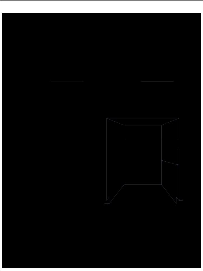
18” Product and Cabinet Opening Dimensions
|
|
|
21 9/16" |
|
|
|
|
|
22 5/16" |
|
|||
|
|
|
|
|
|
|
|
|
|||||
|
|
(54.7 cm) |
|
|
|
|
|
|
|
(56.6 cm) |
|||
|
|
|
|
|
|
|
|
|
|
|
|
|
|
|
|
|
|
|
|
|
|
|
|
|
|
|
|
|
|
|
|
|
|
|
|
|
|
|
|
|
|
|
|
|
|
|
|
|
|
|
|
|
|
|
|
|
|
|
|
|
|
|
|
|
|
|
|
|
|
321/2" |
321/2" |
(82.5 cm) min. |
(82.5 cm) min. |
35" |
35" |
(88.9 cm) max |
(88.9 cm) max |
21 9/16" |
22 5/16" |
(54.7 cm) |
(56.6 cm) |
Side View 18" Custom Wood Panel |
Side View 18" Metal Door Panel |
17 5/8" |
|
(44.7 cm) max |
|
|
18" |
|
(45.7 cm) min. |
32 1/2" |
32 1/2" |
(82.5 cm) min. |
(82.5 cm) min. |
|
|
35" |
24" |
(88.9 cm) max |
|
|
(61 cm) |
|
min. |
Front View
NOTE: Route the water supply line and power cable through the channels provided under the dishwasher (circled above).
Cutout Dimensions
Underside of countertop to oor
The enclosure must be at least 18" wide, 24" (61 cm) deep, and 32½" (82.5 cm) high.
For the front door of the dishwasher to be ush with the leading edge of the counter top, the counter top must be at least 24" (61 cm) deep.
This dishwasher is designed to be enclosed on the top and on both sides by a standard residential kitchen cabinet unit.
The installation enclosure must be clean and free of any obstructions.
NOTE: ADA installation, 32½" (82.5 cm) beneath 34" (86.4 cm) high countertops may be accomplished by adjusting the toekick and leveling legs.
1-4 n 18” & 24” ADA Built-In Dishwashers
GENERAL INFORMATION
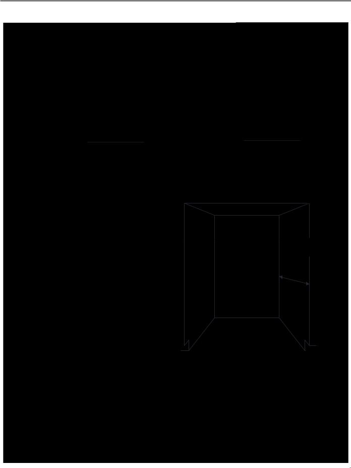
24” Product and Cabinet Opening Dimensions
|
|
|
21 9/16" |
|
|
|
|
|
22 5/16" |
|
|||
|
|
|
|
|
|
|
|
|
|||||
|
|
|
|
|
|
|
|||||||
|
|
|
|
||||||||||
|
|
(54.7 cm) |
|
|
|
|
|
|
|
(56.6 cm) |
|||
|
|
|
|
|
|
|
|
|
|
|
|
|
|
|
|
|
|
|
|
|
|
|
|
|
|
|
|
|
|
|
|
|
|
|
|
|
|
|
|
|
|
|
|
|
|
|
|
|
|
|
|
|
|
|
|
|
|
|
|
|
|
|
|
|
|
|
|
|
|
|
|
|
|
|
|
|
|
|
|
|
|
|
|
321/2" |
321/2" |
(82.5 cm) min. |
(82.5 cm) min. |
35" |
35" |
(88.9 cm) max |
(88.9 cm) max |
21 9/16" |
22 5/16" |
(54.7 cm) |
(56.6 cm) |
Side View 24" Custom Wood Panel |
Side View 24" Metal Door Panel |
23 1/2" |
|
(59.6 cm) |
|
|
24" |
|
(61 cm) min. |
32 1/2" |
32 1/2" |
|
(82.5 cm) min. |
(82.5 cm) min. |
|
35" |
24" |
|
(88.9 cm) max |
||
(61 cm) |
||
|
||
|
min. |
Front View
NOTE: Route the water supply line and power cable through the channels provided under the dishwasher (circled above).
Cutout Dimensions
Underside of countertop to oor
The enclosure must be at least 24" (61 cm) wide, 24" (61 cm) deep, and 32½" (82.5 cm) high.
For the front door of the dishwasher to be ush with the leading edge of the counter top, the counter top must be at least 24" (61 cm) deep.
This dishwasher is designed to be enclosed on the top and on both sides by a standard residential kitchen cabinet unit.
The installation enclosure must be clean and free of any obstructions.
NOTE: ADA installation, 32½" (82.5 cm) beneath 34" (86.4 cm) high countertops may be accomplished by adjusting the toekick and leveling legs.
18” & 24” ADA Built-In Dishwashers n 1-5

GENERAL INFORMATION
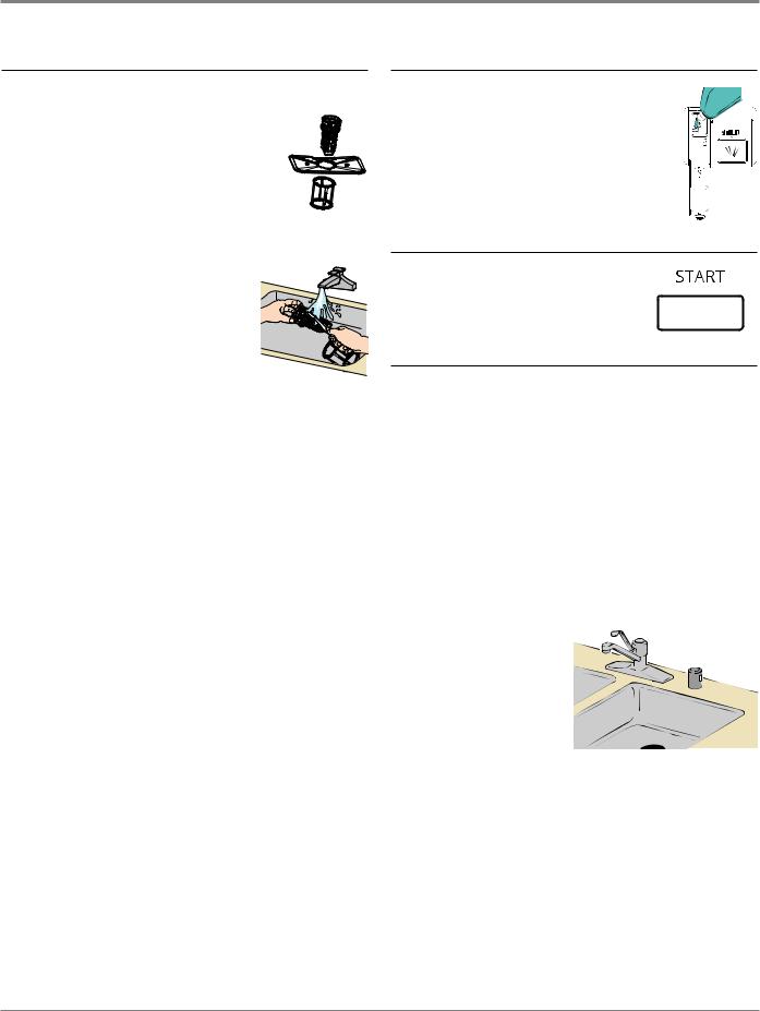
Model & Serial Number Label
Model & Serial Number
Label Location
(Rt. Side, Inner Door)
Figure 7 - Model/Serial Number Label located inside, on left side wall, toward front.
Tech Sheet Location
Tech Sheet Location
(Behind Door Panel)
Figure 8 - Tech Sheet located behind toe panel inside insulation folds.
1-6 n 18” & 24” ADA Built-In Dishwashers
GENERAL INFORMATION
Model & Serial Number Nomenclature
MODEL NUMBER |
|
W D F 518 S |
A H W 0 |
|
|||
|
|
|
|
INTERNATIONAL SALES OR
MARKETING CHANNEL
BRAND CLASSIFICATION
W = Whirlpool , U = Unbranded
PRODUCT IDENTIFIER
D = Dishwasher
PRODUCT TYPE
F = Front UI, T = Top UI (Panel Ready)
FEATURE SET
518 = 18” (45 cm) Model, 550 = 24” (60 cm) Model
TUB MATERIAL
S = Stainless Steal
MODEL TYPE
A = ADA
YEAR OF INTRODUCTION
H = 2018
COLOR
W = White, B = Black, S = Stainless Steel, M = Monochromatic Stainless, P = Panel Ready
ENGINEERING CHANGE
0 = Basic Release; 1 = First Revision; 2 = Second Revision
SERIAL NUMBER |
|
F |
|
K |
|
8 |
|
25 |
|
10000 |
|
|
|
|
|
|
|
|
|||||||
|
|
|
|
|
|
|
|
|
|
|
|
|
PRODUCTION SITE |
|
|
|
|
|
|
|
|
|
|
||
F = FINDLAY, OH |
|
|
|
|
|
|
|
|
|
|
||
|
|
|
|
|
|
|
|
|
|
|
|
|
SOURCE PRODUCTION |
|
|
|
|
|
|
|
|
|
|
||
K = HEFEI, CHINA |
|
|
|
|
|
|
|
|
|
|
||
|
|
|
|
|
|
|
|
|
|
|
|
|
YEAR OF PRODUCTION |
|
|
|
|
|
|
|
|
|
|
||
7 = 2017, 8 = 2018 |
|
|
|
|
|
|
|
|
|
|
|
|
|
|
|
|
|
|
|
|
|
|
|
|
|
WEEK OF PRODUCTION |
|
|
|
|
|
|
|
|
|
|
||
|
|
|
|
|
|
|
|
|
|
|
|
|
PRODUCT SEQUENCE NUMBER |
|
|
|
|
|
|
|
|
|
|
||
|
|
|
|
|
|
|
|
|
|
|
|
|
18” & 24” ADA Built-In Dishwashers n 1-7

GENERAL INFORMATION
|
Dishwasher Specifications |
|
|
|
|
Line Voltage/Frequency : |
|
120 VAC / 60 Hz |
|
|
|
Amps : |
|
15 or 20 Amp |
|
|
|
Circuit : |
|
Separate circuit with time-delay fuse or circuit breaker |
|
|
|
|
|
|
Supply Water Pressure : |
|
20 - 100 psi |
|
|
|
Supply Water Temperature : |
|
120° F (49° C) |
|
|
|
Water Charge |
|
Approx. 3.8 L each fill |
|
|
|
|
|
|
Dishwasher Type : |
|
Built-in |
|
|
|
Control Type: |
|
Electronic Control/Tap Touch |
|
|
|
Control Location : |
|
Front (Top-Panel Ready) |
|
|
|
Dispensers : |
|
Detergent and Rinse Aid |
|
|
|
Wash Levels : |
|
4 |
|
|
|
Decibel Level : |
|
50 dBA (18”), 51 dBA (24”) |
|
|
|
Cycles : |
|
18” - (5) Heavy, Light/China, Normal, Quick Wash, Rinse Only |
|
|
24” - (6) Glass, Heavy, Light/China, Normal, Quick Wash, Rinse Only |
|
|
|
Drying System : |
|
Recessed Heating Element |
|
|
|
Tub Material : |
|
Stainless Steel |
|
|
|
Rack Material : |
|
Nylon |
|
|
|
Wash System : |
|
Filter (Removable) |
|
|
|
Racks : |
|
2 |
|
|
|
Lower Spray Arm Rotation : |
|
20 - 40 rpm |
|
|
|
Upper Spray Arm Rotation : |
|
15 - 40 rpm |
|
|
|
|
|
|
ADA Compliant : |
|
Yes |
|
|
|
Energy Star Qualified : |
|
Yes |
|
|
|
Kosher Consumer Friendly : |
|
Yes |
|
|
|
CEE Tier : |
|
Tier 1 |
|
|
|
|
|
|
18” Dishwasher |
|
|
|
|
|
Depth : |
|
22” (55.88 cm) without handles, 22 7/16” (57 cm) with handles |
|
|
|
Height : |
|
34 1/2” (87.63 cm) max., 32 1/2 (82.55 cm) min. |
|
|
|
Width : |
|
17 5/8” (44.70 cm) |
|
|
|
Weight : |
|
75 lbs (34kg) |
|
|
|
|
|
|
24” Dishwasher |
|
|
|
|
|
Depth : |
|
24” (60.96 cm) without handles, 24 7/16” (62.10 cm) with handles |
|
|
|
Height : |
|
34 1/2” (87.63 cm) max., 32 1/2 (82.55 cm) min. |
|
|
|
Width : |
|
23 1/2” (59.69 cm) |
|
|
|
Weight : |
|
105 lbs (47.63kg) |
|
|
|
1-8 n 18” & 24” ADA Built-In Dishwashers

DIAGNOSTICS & TROUBLESHOOTING
Section 2:
Diagnostics &
Troubleshooting
This section provides diagnostic, fault codes, and troubleshooting information for the 18” & 24” ADA Built-In Dishwashers.
Diagnostics & Troubleshooting Safety
Service Mode - 24” Dishwasher, Front Display
Service Mode - 18” Dishwasher, Front Display
Service Mode - 18” & 24” Dishwasher, Top Display
Service Error Codes
Troubleshooting Guide
Customer Troubleshooting Guide
18” & 24” ADA Built-In Dishwashers n 2-1
DIAGNOSTICS & TROUBLESHOOTING
For Service Technician Use Only
 DANGER
Electrical Shock Hazard
Only authorized technicians should perform diagnostic voltage measurements.
After performing voltage measurements, disconnect power before servicing.
Failure to follow these instructions can result in death or electrical shock.
 WARNING
Electrical Shock Hazard Disconnect power before servicing.
Replace all parts and panels before operating.
Failure to do so can result in death or electrical shock.
Voltage Measurement Safety Information
When performing live voltage measurements, you must do the following:
Verify the controls are in the off position so that the appliance does not start when energized.Allow enough space to perform the voltage measurements without obstructions.
Keep other people a safe distance away from the appliance to prevent potential injury.Always use the proper testing equipment.
After voltage measurements, always disconnect power before servicing.
IMPORTANT: Electrostatic Discharge (ESD) Sensitive Electronics
ESD problems are present everywhere. Most people begin to feel an ESD discharge at approximately 3000V. It takes as little as 10V to destroy, damage, or weaken the main control assembly. The new main control assembly may appear to work well after repair is finished, but a malfunction may occur at a later date due to ESD stress.
Use an anti-static wrist strap. Connect wrist strap to green ground connection point or unpainted metal in the appliance
-OR-
Touch your finger repeatedly to a green ground connection point or unpainted metal in the appliance.
Before removing the part from its package, touch the anti-static bag to a green ground connection point or unpainted metal in the appliance.
Avoid touching electronic parts or terminal contacts; handle electronic control assembly by edges only.
When repackaging main control assembly in anti-static bag, observe above instructions.
IMPORTANT SAFETY NOTICE — “For Technicians only”
This service data sheet is intended for use by persons having electrical, electronic, and mechanical experience and knowledge at a level generally considered acceptable in the appliance repair trade. Any attempt to repair a major appliance may result in personal injury and property damage. The manufacturer or seller cannot be responsible, nor assume any liability for injury or damage of any kind arising from the use of this data sheet.
2-2 n 18” & 24” ADA Built-In Dishwashers

DIAGNOSTICS & TROUBLESHOOTING
For Service Technician Use Only
Service Mode
All ADA 18” & 24” dishwashers are programmed with a service mode to aid the technician in troubleshooting the dishwasher. Each component is cycled to verify if it is functioning correctly. Essentially, the procedure to enter service mode is similar between models except for a slight variation in button selection.
To Enter Service Mode—24” Dishwasher, Front Display
Figure 1 - 24” Dishwasher, Front Display
1.Turn the dishwasher off and make sure no LED’s are lit.
2.Disconnect power to the dishwasher.
3.Reapply power with the door open and quickly press and hold both the On/Off and Start/Pause buttons within 60 seconds from connecting power. Close the door and then the dishwasher will run as below.
Service Mode Chart
NO. |
COMPONENT |
SSD* |
NOTE |
|
|
|
|
1 |
WATER VALVE |
05 |
TURN ON WATER VALVE. THE FLOW METER WILL ALLOW 3 L OF WATER |
|
|
TURBIDITY |
TO ENTER THE DISHWASHER. (THIS STEP WILL DISPLAY THE TURBIDITY |
|
|
VALUE |
VALUE ON THE SSD.) |
2 |
WASH PUMP |
04 |
TURN ON THE WASH PUMP. AFTER 10 SECONDS THE HEATER WILL TURN |
|
HEATER |
|
ON. THE BEEPER WILL SOUND WHEN THE TEMPERATURE HAS RISEN 3 - 5 |
|
|
|
DEGREES. THE DISHWASHER WILL STOP WHEN THE TEMPERATURE HAS |
|
|
|
REACHED 57°C. PRESS START TO ENTER THE NEXT STEP. |
3 |
HIGH WASH PUMP |
03 |
TURN ON THE WASH PUMP FOR 8 SECONDS AFTER 2 SECOND DELAY. |
|
DISPENSER |
|
THEN TURN ON THE DISPENSER FOR 45 SECONDS. |
4 |
PAUSE |
02 |
PAUSE FOR 30 SECONDS. |
|
|
|
|
5 |
DRAIN PUMP |
01 |
TURN ON THE DRAIN PUMP FOR 30 SECONDS. |
|
|
|
|
6 |
END |
BOARD TYPE |
BEEP ONE TIME. (THE SSD WILL SHOW THE BOARD TYPE CODE.) |
|
|
CODE |
|
*SSD = Seven |
Segment Display |
|
|
To Exit Service Mode:
Disconnect power to the dishwasher.
18” & 24” ADA Built-In Dishwashers n 2-3

DIAGNOSTICS & TROUBLESHOOTING
For Service Technician Use Only
To Enter Service Mode—18” Dishwasher, Front Display
Figure 1 - 18” Dishwasher, Front Display
1.Turn the dishwasher off and make sure no LED’s are lit.
2.Disconnect power to the dishwasher.
3.Reapply power with the door open and quickly press and hold both the Cycles and Start/Cancel buttons within 60 seconds from connecting power. Close the door and then the dishwasher will run as below.
Service Mode Chart
NO. |
COMPONENT |
SSD* |
NOTE |
|
|
|
|
1 |
WATER VALVE |
05 |
TURN ON WATER VALVE. THE FLOW METER WILL ALLOW 3 L OF WATER |
|
|
TURBIDITY |
TO ENTER THE DISHWASHER. (THIS STEP WILL DISPLAY THE TURBIDITY |
|
|
VALUE |
VALUE ON THE SSD.) |
2 |
WASH PUMP |
04 |
TURN ON THE WASH PUMP. AFTER 10 SECONDS THE HEATER WILL TURN |
|
HEATER |
|
ON. THE BEEPER WILL SOUND WHEN THE TEMPERATURE HAS RISEN 3 - 5 |
|
|
|
DEGREES. THE DISHWASHER WILL STOP WHEN THE TEMPERATURE HAS |
|
|
|
REACHED 57°C. PRESS START TO ENTER THE NEXT STEP. |
3 |
HIGH WASH PUMP |
03 |
TURN ON THE WASH PUMP FOR 8 SECONDS AFTER 2 SECOND DELAY. |
|
DISPENSER |
|
THEN TURN ON THE DISPENSER FOR 45 SECONDS. |
4 |
PAUSE |
02 |
PAUSE FOR 30 SECONDS. |
|
|
|
|
5 |
DRAIN PUMP |
01 |
TURN ON THE DRAIN PUMP FOR 30 SECONDS. |
|
|
|
|
6 |
END |
BOARD TYPE |
BEEP ONE TIME. (THE SSD WILL SHOW THE BOARD TYPE CODE.) |
|
|
CODE |
|
*SSD = Seven |
Segment Display |
|
|
To Exit Service Mode:
Disconnect power to the dishwasher.
2-4 n 18” & 24” ADA Built-In Dishwashers
DIAGNOSTICS & TROUBLESHOOTING
For Service Technician Use Only
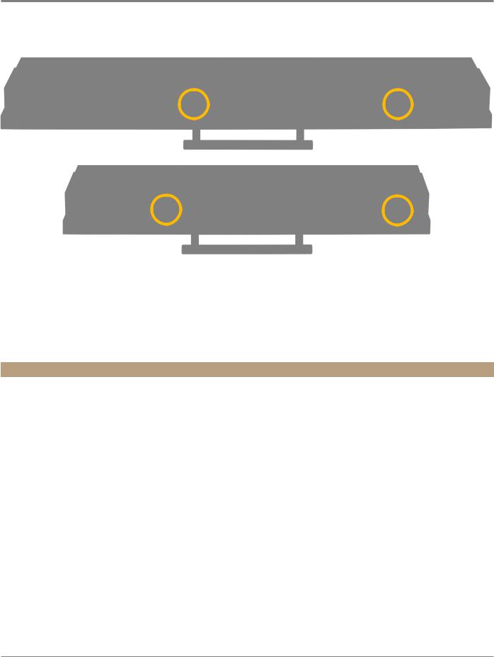
To Enter Service Mode—18” & 24” Dishwasher, Top Display (Panel Ready)
Figure 1 - 24” Dishwasher, Top Display
Figure 2 - 18” Dishwasher, Top Display
1.Turn the dishwasher off and make sure no LED’s are lit.
2.Disconnect power to the dishwasher.
3.Reapply power with the door open and quickly press and hold both the Rinse and Start buttons within 60 seconds from connecting power. Close the door and then the dishwasher will run as below.
Service Mode Chart
NO. |
COMPONENT |
SSD* |
NOTE |
|
|
|
|
1 |
WATER VALVE |
05 |
TURN ON WATER VALVE. THE FLOW METER WILL ALLOW 3 L OF WATER |
|
|
TURBIDITY |
TO ENTER THE DISHWASHER. (THIS STEP WILL DISPLAY THE TURBIDITY |
|
|
VALUE |
VALUE ON THE SSD.) |
2 |
WASH PUMP |
04 |
TURN ON THE WASH PUMP. AFTER 10 SECONDS THE HEATER WILL TURN |
|
HEATER |
|
ON. THE BEEPER WILL SOUND WHEN THE TEMPERATURE HAS RISEN 3 - 5 |
|
|
|
DEGREES. THE DISHWASHER WILL STOP WHEN THE TEMPERATURE HAS |
|
|
|
REACHED 57°C. PRESS START TO ENTER THE NEXT STEP. |
3 |
HIGH WASH PUMP |
03 |
TURN ON THE WASH PUMP FOR 8 SECONDS AFTER 2 SECOND DELAY. |
|
DISPENSER |
|
THEN TURN ON THE DISPENSER FOR 45 SECONDS. |
4 |
PAUSE |
02 |
PAUSE FOR 30 SECONDS. |
|
|
|
|
5 |
DRAIN PUMP |
01 |
TURN ON THE DRAIN PUMP FOR 30 SECONDS. |
|
|
|
|
6 |
END |
BOARD TYPE |
BEEP ONE TIME. (THE SSD WILL SHOW THE BOARD TYPE CODE.) |
|
|
CODE |
|
*SSD = Seven |
Segment Display |
|
|
To Exit Service Mode:
Disconnect power to the dishwasher.
18” & 24” ADA Built-In Dishwashers n 2-5
DIAGNOSTICS & TROUBLESHOOTING
For Service Technician Use Only
Service Error Codes
 DANGER
Electrical Shock Hazard
Only authorized technicians should perform diagnostic voltage measurements.
After performing voltage measurements, disconnect power before servicing.
Failure to follow these instructions can result in death or electrical shock.
Failure Solutions:
1.If an alarm occurs, the machine will enter a failure solving process: The buzzer sounds once per second for 30 seconds. The error code will be displayed. During that time, the drain pump will turn on for 2 minutes.
2.During the drain, if the door is opened, the drain timing will pause.
ERROR |
ERROR |
ERROR |
CAUSES |
WHAT TO CHECK |
CODE |
CODE |
|
|
|
SSD* |
NON-SSD* |
|
|
|
|
|
|
|
|
E1 |
“QUICK” |
WATER INLET |
DURING THE WATER INLET |
1. CHECK THE WATER SUPPLY. |
INDICATOR |
FAILURE |
STEP, IF THE FLOW METER |
2. CHECK THE INLET VALVE. |
|
|
FLASHES |
|
CAN’T DETECT A CORRECT |
|
|
|
3. CHECK THE INLET. |
||
|
|
|
FILL AFTER 4 MINUTES, E1 |
|
|
|
|
WILL BE DISPLAYED. |
4. CHECK THE FLOW METER. |
|
|
|
|
5. CHECK THE PRESSURE SWITCH. |
|
|
|
|
6. CHECK THE DRAIN. |
|
|
|
|
7. CHECK THE CONTROL. |
|
|
|
|
|
E3 |
“QUICK” |
HEATER FAILURE |
WHEN THE TEMPERATURE |
1. CHECK THE HEATER. |
& “GLASS” |
|
DOESN’T REACH THE |
2. CHECK THE THERMISTOR. |
|
|
INDICTORS |
|
CORRECT VALUE AFTER |
|
|
|
3. CHECK THE CONTROL. |
||
|
FLASH |
|
90 MINUTES, E3 WILL BE |
|
|
|
|
||
|
|
|
DISPLAYED. |
|
|
|
|
|
|
E4 |
“LIGHT” |
OVERFLOW |
IF WATER FLOWS INTO THE |
1. CHECK THE USE OF THE DETERGENT. |
INDICATOR |
|
BASE AND ACTIVATES THE |
2. CHECK WHETHER THE APPLIANCE IS LEVEL. |
|
|
FLASHES |
|
OVERFLOW SWITCH, THE |
|
|
|
3. CHECK THE OVERFLOW SWITCH. |
||
|
|
|
DISHWASHER WILL DISPLAY |
|
|
|
|
E4. |
4. CHECK THE DRAIN PUMP. |
|
|
|
|
5. CHECK THE AMOUNT OF WATER IN SUMP. |
|
|
|
|
6. LOCATE LEAK AND REPAIR. |
|
|
|
|
|
E6 |
“LIGHT” & NTC OPEN CIRCUIT |
TEMPERATURE SENSOR |
1. CHECK THE INLET WATER TEMPERATURE. |
|
“GLASS” |
FAILURE |
OPEN CIRCUIT, E6 WILL BE |
2. CHECK THE THERMISTOR. |
|
|
INDICATORS |
|
DISPLAYED. |
|
|
|
3. CHECK THE CONTROL. |
||
|
FLASH |
|
|
|
|
|
|
|
|
|
|
|
|
|
E7 |
“LIGHT, |
NTC SHORT |
TEMPERATURE SENSOR |
1. CHECK THE INLET WATER TEMPERATURE. |
GLASS, & |
CIRCUIT FAILURE |
SHORT CIRCUIT, E7 WILL BE |
2. CHECK THE THERMISTOR. |
|
|
QUICK” |
|
DISPLAYED. |
|
|
|
3. CHECK THE CONTROL. |
||
|
INDICATORS |
|
|
|
|
|
|
|
|
|
FLASH |
|
|
|
*SSD: Seven Segment Display (Not available on 24” Front Display Dishwashers.)
2-6 n 18” & 24” ADA Built-In Dishwashers
DIAGNOSTICS & TROUBLESHOOTING
For Service Technician Use Only
Troubleshooting Guide
 DANGER
Electrical Shock Hazard
Only authorized technicians should perform diagnostic voltage measurements.
After performing voltage measurements, disconnect power before servicing.
Failure to follow these instructions can result in death or electrical shock.
DESCRIPTION |
POTENTIAL CAUSES |
CHECK |
|||
|
|
|
|||
WON’T RUN OR POWER |
NO POWER TO UNIT OR BAD CONNECTION |
CHECK FUSES, CIRCUIT BREAKERS AND JUNCTION BOX |
|||
UP (“DEAD” KEYPAD/ |
|
CONNECTIONS. |
|||
CONSOLE) |
|
|
|
||
LOOSE CONNECTIONS IN DISHWASHER |
1. |
UNPLUG DISHWASHER OR DISCONNECT POWER. |
|||
¾¾ |
NO OPERATION |
||||
POWER UP CIRCUIT OR BETWEEN |
2. |
CHECK RESISTANCE OF ALL CONNECTIONS |
|||
¾¾ |
NO KEYPAD RESPONSE |
||||
KEYPAD(S) AND CONTROL |
|||||
|
IN POWER UP CIRCUIT TO CONTROL. CHECK |
||||
¾¾ NO LEDS OR DISPLAY |
|
|
|||
|
|
CONNECTIONS BETWEEN KEYPAD(S) AND |
|||
|
|
|
|
||
|
|
|
|
CONTROL. |
|
|
|
|
|
|
|
|
|
DOOR SWITCH NOT MAKING CONTACT: |
1. |
UNPLUG DISHWASHER OR DISCONNECT POWER. |
|
|
|
¾¾ FAULTY DOOR LATCH ASSEMBLY |
2. |
MEASURE RESISTANCE OF DOOR SWITCH |
|
|
|
¾¾ FAULTY DOOR SWITCH |
|
CONTACTS WHILE CHECKING MECHANICAL |
|
|
|
|
OPERATION OF LATCH ASSEMBLY. CONFIRM |
||
|
|
|
|
||
|
|
|
|
SWITCHES NOT LOOSE FROM ASSEMBLY. |
|
|
|
|
|
||
|
|
MULTIPLE OPEN OR SHORTED CIRCUITS IN |
SEE “CHECKING KEYPAD OPERATION”. |
||
|
|
KEYPAD |
|
|
|
|
|
FAULTY CONTROL |
1. |
UNPLUG DISHWASHER OR DISCONNECT POWER. |
|
|
|
|
2. |
CHECK/REPLACE CONTROL. |
|
|
|
|
|||
WON’T RUN AND LED |
BY DESIGN, IF THE DOOR IS OPENED |
INSTRUCT CUSTOMER, REFER TO USE AND CARE |
|||
FOR START/RESUME |
OR POWER IS INTERRUPTED DURING A |
GUIDE. |
|||
KEY IS DEAD |
CYCLE, THE USER MUST PRESS THE START/ |
|
|
||
|
|
RESUME KEY TO RESUME OPERATION. |
|
|
|
|
|
THE DOOR MUST BE LATCHED FOR THE |
CONFIRM DOOR IS CLOSED PROPERLY BEFORE |
||
|
|
START/RESUME KEY TO WORK |
PRESSING START/RESUME KEY. INSTRUCT CUSTOMER |
||
|
|
|
TO REFER TO USE AND CARE GUIDE. |
||
|
|
DOOR SWITCH NOT MAKING CONTACT: |
1. |
UNPLUG DISHWASHER OR DISCONNECT POWER. |
|
|
|
¾¾ FAULTY OR LOOSE DOOR LATCH |
2. |
MEASURE RESISTANCE OF DOOR SWITCH |
|
|
|
ASSEMBLY (WHICH CAN BE |
|
CONTACTS WHILE CHECKING MECHANICAL |
|
|
|
AGGRAVATED BY HIGH DOOR CLOSURE |
|
OPERATION OF LATCH ASSEMBLY. CONFIRM |
|
|
|
FORCE) |
|
SWITCHES NOT LOOSE FROM ASSEMBLY. CHECK |
|
|
|
¾¾ FAULTY DOOR SWITCH (HIGH |
|
STRIKE PLATE AND DOOR CLOSURE. |
|
|
|
RESISTANCE) |
3. |
CHECK/REPLACE CONTROL. |
|
|
|
¾¾ FAULTY CONTROL DOES NOT DETECT |
|
|
|
|
|
DOOR CLOSED |
|
|
|
|
|
START/RESUME KEY NOT RESPONDING |
SEE “ONE OR MORE KEYS WON’T RESPOND” |
||
|
|
|
PROBLEM BELOW. |
||
18” & 24” ADA Built-In Dishwashers n 2-7

DIAGNOSTICS & TROUBLESHOOTING
For Service Technician Use Only
Troubleshooting Guide (continued)
DESCRIPTION |
POTENTIAL CAUSES |
CHECK |
|
|
|
|
|
CONTROL LOCK WON’T |
INTERMITTENT OPEN OR SHORT OF |
SEE “CHECKING KEYPAD OPERATION”. |
|
ACCEPT KEY PRESSES, |
HEATED DRY KEY OR CIRCUIT IN KEYPAD OR |
|
|
CONTROL LOCK LED ON |
KEYPAD CONNECTION |
|
|
ONE OR MORE KEYS |
OPEN KEY OR LED CIRCUIT(S) ON THE |
SEE “CHECKING KEYPAD OPERATION”. |
|
WON’T RESPOND |
KEYPAD, OR OPEN CIRCUITS ON THE |
|
|
|
CONTROL TO THE KEYS AND LEDS. |
|
|
|
DOOR SWITCH NOT MAKING CONTACT. |
1. |
UNPLUG DISHWASHER OR DISCONNECT POWER. |
|
¾¾ FAULTY OR LOOSE DOOR LATCH |
2. |
MEASURE RESISTANCE OF DOOR SWITCH |
|
ASSEMBLY(WHICHCANBEAGGRAVATED |
|
CONTACTS WHILE CHECKING MECHANICAL |
|
BY HIGH DOOR CLOSURE FORCE) |
|
OPERATION OF LATCH ASSEMBLY. CONFIRM |
|
¾¾ FAULTY DOOR SWITCH (HIGH |
|
SWITCHES NOT LOOSE FROM ASSEMBLY. CHECK |
|
|
STRIKE PLATE AND DOOR CLOSURE. |
|
|
RESISTANCE) |
|
|
|
3. |
CHECK/REPLACE CONTROL. |
|
|
¾¾ FAULTY CONTROL DOES NOT DETECT |
||
|
DOOR CLOSED. |
|
|
WILL NOT FILL OR LOW |
LOW WATER PRESSURE OR NO WATER TO |
VERIFY WATER IS TURNED ON AND SUPPLY LINE |
|
WATER |
DISHWASHER |
ADEQUATE. CORRECT INSTALLATION AS NECESSARY. |
|
|
LOOSE CONNECTION TO DISHWASHER FILL |
1. |
UNPLUG DISHWASHER OR DISCONNECT POWER. |
|
VALVE, OR IN THE VALVE CIRCUIT OR IN |
2. |
CHECK RESISTANCES OF FILL VALVE SOLENOID |
|
FILL VALVE SOLENOID |
||
|
|
AND ALL CONNECTIONS IN THE FILL CIRCUIT. |
|
|
|
|
|
|
|
|
|
|
DRAIN LOOP DETACHED FROM TUB AND/ |
CHECK FOR WATER SIPHONING OUT OF THE UNIT: |
|
|
OR IMPROPER DRAIN CONNECTION |
1. |
ALLOW DISHWASHER TO COMPLETE A NORMAL |
|
|
|
FILL. |
|
|
2. |
DRAIN FOR 5-10 SECONDS BY PRESSING CANCEL/ |
|
|
|
DRAIN. |
|
|
3. |
OPEN DOOR AND CONFIRM WATER DOES NOT |
|
|
|
SIPHON OUT OF UNIT IF IT DOES, CONFIRM |
|
|
|
DRAIN LOOP IS ATTACHED TO SIDE OF |
|
|
|
DISHWASHER AND DRAIN HOSE IS CONNECTED |
|
|
|
TO A DRAIN AT LEAST 50.8 CM (20 INCHES) OFF |
|
|
|
THE FLOOR. |
|
INLET SCREEN ON FILL VALVE PLUGGED |
DISCONNECT WATER LINE TO FILL VALVE AND INSPECT |
|
|
|
INLET FOR OBSTRUCTION. |
|
|
FAULTY FILL VALVE DRIVE CIRCUIT ON THE |
CHECK OPERATION OF FILL VALVE BY CONTROL |
|
|
CONTROL |
DURING DIAGNOSTICS. |
|
|
CUSTOMER MISUNDERSTANDS PROPER |
CUSTOMER INSTRUCT: |
|
|
WATER LEVEL |
NORMAL WATER LEVEL IS JUST ABOVE FILTER SCREEN. |
|
|
|
||
|
|
|
|
WASH PUMP WILL NOT |
PUMP MOTOR SEIZED UP (WILL NOT TURN) |
1. |
UNPLUG DISHWASHER OR DISCONNECT POWER. |
PUMP |
|
|
|
|
|
|
|
|
PUMP MOTOR WINDINGS OPEN OR |
1. |
UNPLUG DISHWASHER OR DISCONNECT POWER. |
|
LOOSE/OPEN CONNECTION IN WASH |
2. |
CHECK RESISTANCE OF PUMP MOTOR WINDINGS |
|
PUMP CIRCUIT |
||
|
|
AND ALL CONNECTIONS IN THE WASH CIRCUIT |
|
|
|
|
INCLUDING THE PUMP MOTOR CAPACITOR. |
2-8 n 18” & 24” ADA Built-In Dishwashers
Loading...