


SKT60*TRIM KIT INSTALLATION INSTRUCTIONS
INSTRUCCIONES DE INSTALACIÓN DEL JUEGO
DE MARCOS SKT60*
INSTRUCTIONS D’INSTALLATION DE L’ENSEMBLE
D’OBTURATION SKT60*
W10691539C
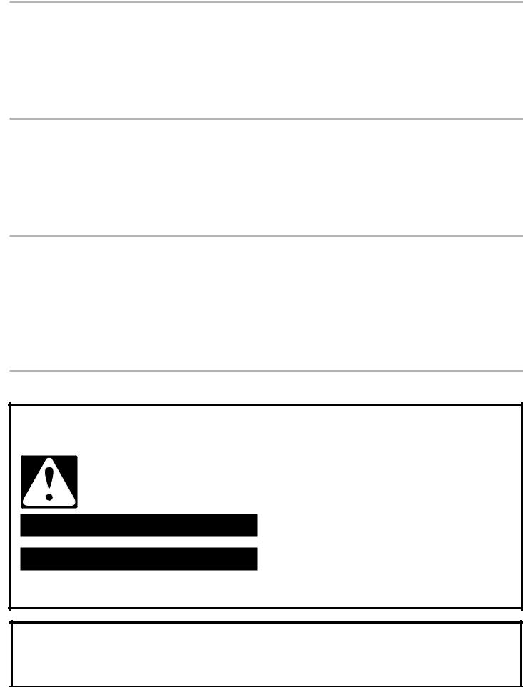
TABLE OF CONTENTS
SKT60* TRIM KIT SAFETY............................................................. |
2 |
INSTALLATION REQUIREMENTS................................................. |
3 |
Plan the Installation....................................................................... |
3 |
Opening Requirements................................................................. |
3 |
Tools Needed................................................................................ |
3 |
Parts Supplied.............................................................................. |
3 |
Electrical Requirements................................................................ |
4 |
ASSEMBLY INSTRUCTIONS.......................................................... |
4 |
Assemble the Top Grille................................................................ |
4 |
Attach the Side Rails.................................................................... |
5 |
INSTALLATION INSTRUCTIONS................................................... |
5 |
Install the Top Grille and Trim Assembly...................................... |
5 |
Place and Align Refrigerator and Freezer..................................... |
6 |
Move Refrigerator and Freezer to Final Location......................... |
7 |
Care and Cleaning........................................................................ |
8 |
ÍNDICE
SEGURIDAD DEL JUEGO DE MARCOS SKT60*......................... |
9 |
REQUISITOS DE INSTALACIÓN.................................................... |
9 |
Planifique la instalación................................................................ |
9 |
Requisitos para la abertura.......................................................... |
9 |
Herramientas necesarias............................................................ |
10 |
Piezas suministradas.................................................................. |
10 |
Requisitos eléctricos................................................................... |
11 |
INSTRUCCIONES DE ENSAMBLAJE......................................... |
11 |
Ensamble la rejilla superior......................................................... |
11 |
Sujete las extrusiones de los marcos laterales.......................... |
12 |
IINSTRUCCIONES DE INSTALACIÓN......................................... |
12 |
Instale el ensamblaje de la rejilla superior y del marco.............. |
12 |
Coloque y alinee el refrigerador y el congelador........................ |
13 |
Mueva el refrigerador y el congelador a su ubicación final....... |
14 |
Cuidado y limpieza..................................................................... |
16 |
TABLE DES MATIÈRES
SÉCURITÉ DE L’ENSEMBLE D’OBTURATION SKT60*............ |
17 |
EXIGENCES D’INSTALLATION.................................................... |
17 |
Planification de l’installation....................................................... |
17 |
Exigences d’ouverture................................................................ |
17 |
Outillage nécessaire.................................................................... |
18 |
Pièces fournies........................................................................... |
18 |
Spécifications électriques........................................................... |
19 |
INSTRUCTIONS D’ASSEMBLAGE.............................................. |
19 |
Assemblage de la grille supérieure............................................. |
19 |
Fixation des rails latéraux........................................................... |
20 |
INSTRUCTIONS D’INSTALLATION............................................. |
20 |
Installation de la grille et de la garniture supérieures................. |
20 |
Installation et alignement du réfrigérateur |
|
et du congélateur........................................................................ |
21 |
Déplacement du réfrigérateur et du congélateur |
|
à leur emplacement définitif....................................................... |
22 |
Entretien et nettoyage................................................................. |
24 |
SKT60*TRIM KIT SAFETY
Your safety and the safety of others are very important.
many important safety messages in this manual and on your appliance. Always read and obey all safety
safety alert symbol.
alerts you to potential hazards that can kill or hurt you and others.
messages will follow the safety alert symbol and either the word “DANGER” or “WARNING.” mean:
 DANGER
  WARNING
You can be killed or seriously injured if you don't immediately follow instructions.
You can be killed or seriously injured if you don't follow instructions.
All safety messages will tell you what the potential hazard is, tell you how to reduce the chance of injury, and tell you what can happen if the instructions are not followed.
State of California Proposition 65 Warnings:
WARNING: This product contains one or more chemicals known to the State of California to cause cancer.
WARNING: This product contains one or more chemicals known to the State of California to cause birth defects or other reproductive harm.
2

INSTALLATION REQUIREMENTS
The SKT60* Trim Kit provides an integrated appearance when installing an all-refrigerator and upright freezer side by side.
Plan the Installation
Plan your installation using these instructions in conjunction with the Use & Care Guides provided with the refrigerator and freezer.
IMPORTANT:
■■ For ease in handling and alignment, it is required that 2 people install the trim kit.
■■ Make sure there is enough area, approximately 7 ft (2.1 m) by 10 ft (3.1 m) to assemble parts on the floor.
■■ Lay a drop cloth on the floor to cushion the parts and cover the flooring.
■■ These instructions are intended as a general guide only and do not supersede any national or local codes in any way. Compliance with all local, state or national codes pertaining to this type of installation should be determined prior to installation.
Opening Requirements
Make sure the opening is 74¹⁄2" (189.2 cm) high by 62¹⁄8" (157.8 cm) wide by 24¹⁄4" (61.6 cm) deep as shown.
The inner opening dimensions of the installed trim kit will be 61.31" (155.7 cm) wide by 66.85" (189.7 cm) high.
NOTE: It is possible to make the trim kit fit vertical openings that are less than 74¹⁄2" (189.2 cm) high. The trim kit can be reduced in height by 1" (2.54 cm) increments. Each top grille (B) section is 1" (2.54 cm) in height. For each top grille (B) section that is not used, 1" (2.54 cm) must be cut from the base of both the left-hand (E) and right-hand (G) side trim pieces.
24¼" (61.6 cm) 
74½" (189.2 cm)
62⅛"
(157.8 cm)
Tools Needed
Assemble the required tools and parts before starting installation.
Read and follow the instructions provided with any of the required tools listed here. Proper installation is your responsibility.
Tools Needed |
|
|
|
■■ |
Cordless drill, ¹⁄8" bit |
■■ |
Torx®† T25 screwdriver |
■■ |
Phillips screwdriver |
■■ |
Carpenter’s level |
■■ |
Flat-blade screwdriver |
■■ |
Tape measure |
■■ Socket drive #2 bits |
■■ Tape (masking or painters) |
||
Parts Supplied
Remove the parts from the trim kit package. Make sure all parts are included.
IMPORTANT:
■■ Do not use sharp objects to remove packaging materials to avoid scratching surfaces.
■■ The metal parts can be damaged if they are dropped.
A 
B 
C 
D
E 
 G
G
F
|
|
H |
|
|
J |
|
|
I |
|
Stainless |
|
Description (Quantity) |
Steel Part |
White Part |
Number |
Number |
|
A. Top Trim Mount (1) |
W10682840 |
W10682841 |
B. Top Grille (6) (shown assembled) |
W10682846 |
W10682847 |
C. Top Trim Notched Grille (1) |
W10682843 |
W10682844 |
D. Top Plate (1) |
W10682876 |
W10682875 |
E. Left-Hand Side Trim (1) |
W10682850 |
W10682851 |
F. Gap Filler (1) |
W10682856 |
W10682857 |
G. Right-Hand Side Trim (1) |
W10682853 |
W10682854 |
H. Bottom Grille Assembly (1) |
W10682833 |
W10682834 |
I. Rear spacer (2) |
W10682858 |
W10682858 |
J. Bottom plate (1) |
W10907484 |
|
†®TORX is a registered trademark of ACUMENT INTELLECTUAL PROPERTIES, LLC
3
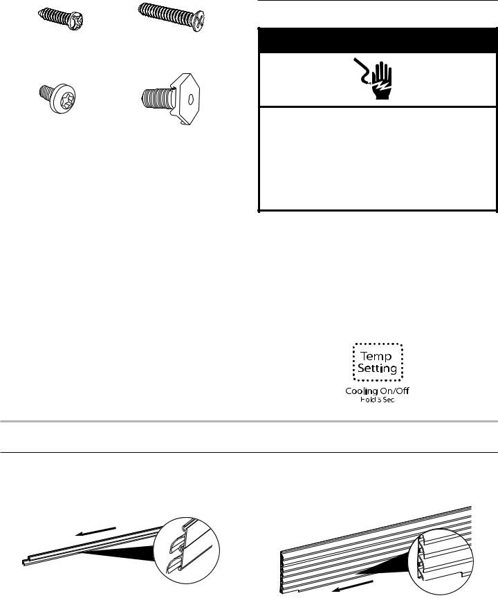
J. Pan-Head Phillips Screw (7) |
K. Countersunk Phillips Screw (2) |
Part Number 3-24004-091 |
Part Number 3-24004-159 |
L. Painted Pan-Head Torx®† |
M. Leveler Leg (4) |
Screw (4) White Kit Part |
Part Number 3-82710-001 |
Number W10383593 |
|
Stainless Steel Kit Part Number |
|
W10385275 |
|
Electrical Requirements
 WARNING
Electrical Shock Hazard Plug into a grounded 3 prong outlet. Do not remove ground prong.
Do not use an adapter.
Do not use an extension cord.
Failure to follow these instructions can result in death, fire, or electrical shock.
Before you move your freezer or refrigerator into its final location, it is important to make sure you have the proper electrical connection.
Recommended Grounding Method
A 115 Volt, 60 Hz., AC only, 15or 20-amp fused, grounded electrical supply is required. It is recommended that a separate circuit serving only your freezer be provided. Use an outlet that cannot be turned off by a switch. Do not use an extension cord.
NOTE: Before performing any type of installation, cleaning, or removing a light bulb, press and hold TEMP SETTING for 3 seconds to turn off cooling, and then disconnect the freezer r refrigerator from the electrical source.
ASSEMBLY INSTRUCTIONS
Assemble theTop Grille
1.Assemble the six top grille (B) sections by sliding one into the other through the tongue and groove feature as shown.
2.Attach the top trim notched grille (C) to those already assembled by sliding it into the bottom/lowest grille section.
4
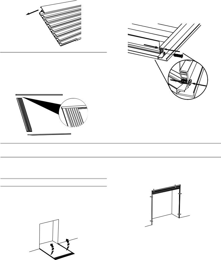
3.Install the top trim mount (A) onto the top grille assembly (B) by sliding it onto the grille section at the top.
2.Align the hole in the side trim piece (E and G) with the groove on the top grille (B) on each side of the grille assembly. There will be a ³⁄8" (9.5 mm) gap between side trim piece (E and G) and top grille (B).
3.Using the two countersunk Phillips screws (K) (provided), fasten the side trim piece (E and G) to the top grille assembly
(B). Insert the screw through the predrilled hole and into the groove on each side of the top grille assembly (B) as shown.
³⁄"
(9.5 mm)
Attach the Side Rails
1.Align the side trim pieces (E, G) with the sides of the top grille assembly (B).
NOTE: Make sure all the grille pieces are contained within the channel of the side trim pieces (E and G) and the top surface of the top grille (B) is flush with the top surface
of the sides.
INSTALLATION INSTRUCTIONS
Install theTop Grille andTrim Assembly
IMPORTANT: The top grille and trim assembly, and your floor can be damaged if the assembly is dropped.
Prepare the Opening
1.Place cardboard or hardboard over the floor at each side of the rough opening where the side trim will meet the floor.
2.Place the top grille and trim assembly face down on the floor centered in front of the rough opening.
3.Using two people, one on each side, lift the trim assembly and position it into place above and on each side of the opening.
4.Use several pieces of tape to temporarily hold the assembly in place as shown.
5.Mark the trim assembly hole locations around the opening. Remove the tape and lower the trim assembly back to the floor.
6.Using a cordless drill and ¹⁄8" diameter drill bit, drill holes where marked.
NOTE: Some cabinetry or wall materials may require predrilled holes using a 7⁄8" diameter drill bit.
7.Repeat steps 3 and 4.
5
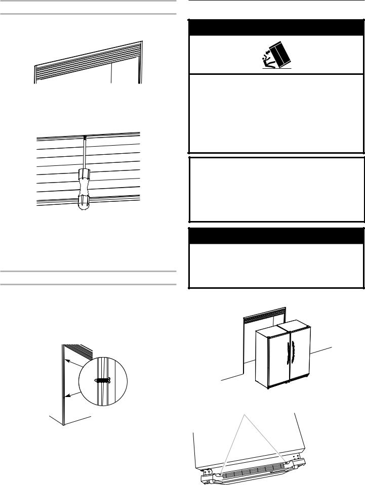
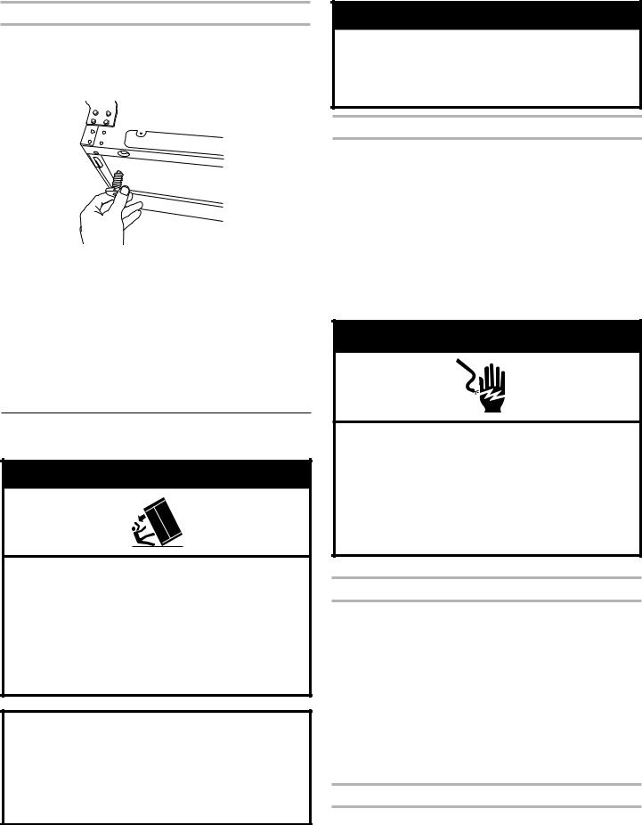
Fasten the Top Trim to the Opening
1.Align the top grille assembly against the opening, so that
it is tight and flush with the front surface of the wall opening or cabinetry.
2.From below and behind the top grille assembly, insert a panhead Phillips screw (J) through the predrilled center hole of the top grille (B) and into the wall opening or cabinetry. NOTE: Do not completely tighten the screw.
3.Using a carpenter’s level, level the top grille assembly (B), and shim as necessary.
NOTE: Shims are not provided with the trim kit.
4.Using two pan-head Phillips screws (J), fasten the top grille assembly (B) by inserting a screw through the predrilled holes at each end. Completely tighten the screws.
5.Completely tighten the center screw.
Fasten the Side Trim to the Opening
1.Using a carpenters level, make sure the sides are plumb and shim as necessary.
NOTE: Shims are not provided with the trim kit.
2.Using four pan-head Phillips screws (J) (two on each side), fasten both the left-hand (E) and right-hand side trim pieces
(G) to the opening or cabinetry. Make sure the trim pieces do not twist.
Place and Align Refrigerator and Freezer
 WARNING
Tip Over Hazard
Refrigerator is top heavy and tips easily when not completely installed.
Keep doors taped closed until refrigerator is completely installed.
Use two or more people to move and install refrigerator.
Failure to do so can result in death or serious injury.
When Moving Your Freezer or Refrigerator:
Your freezer and refrigerator are heavy. When moving the appliance for cleaning or service, be sure to cover the floor with cardboard or hardboard to avoid floor damage. Always pull the appliance straight out when moving it. Do not wiggle or “walk” the appliance when trying to move it, as floor damage could occur.
 WARNING
Excessive Weight Hazard
Use two or more people to move and install refrigerator.
Failure to do so can result in back or other injury.
1.Place the freezer and refrigerator in front of the opening (freezer on the left, refrigerator on the right).
2.Remove the plastic base grille from each appliance by removing the two Phillips screws.
A
A. Screw locations
6
Install Leveler Legs
1.Remove the four hex-head screws on each roller assembly. Set the roller assemblies aside.
2.Place the refrigerator/freezer on its back on top of a piece of cardboard or other protective material.
3.Insert two plastic leveler legs (M) into each cabinet.
4.Return refrigerator/freezer to an upright position.
5.Adjust the leveler legs (M) so that each appliance is level, plumb and at the same height as the other appliance.
NOTE: Now, the freezer and refrigerator each have two front leveler legs (M) that are adjustable. The back of each cabinet rests on two fixed supports.
6.Place a leveling tool on top of the cabinet. Check the level first side to side and then front to back.
To raise a corner – Turn the leveler leg clockwise.
To lower a corner – Turn the leveler leg counterclockwise.
7.Repeat Step 3 for the other appliance until both the freezer and refrigerator are level, plumb and at the same height.
Move Refrigerator and Freezer to Final Location
 WARNING
Tip Over Hazard
Refrigerator is top heavy and tips easily when not completely installed.
Keep doors taped closed until refrigerator is completely installed.
Use two or more people to move and install refrigerator.
Failure to do so can result in death or serious injury.
When Moving Your Freezer or Refrigerator:
Your freezer and refrigerator are heavy. When moving the appliance for cleaning or service, be sure to cover the floor with cardboard or hardboard to avoid floor damage. Always pull the appliance straight out when moving it. Do not wiggle or “walk” the appliance when trying to move it, as floor damage could occur.
 WARNING
Excessive Weight Hazard
Use two or more people to move and install refrigerator.
Failure to do so can result in back or other injury.
Move the First Appliance
IMPORTANT: If the electrical outlets are not centered in the back wall of the opening, move the appliance on the opposite side of the outlets into the opening first.
1.Cover the floor with cardboard or hardboard to avoid floor damage.
2.Attach a plastic foam rear spacer (I) to the rear center of both appliances.
NOTE: The rear spacers (I) ensure that the 2 appliances are positioned the correct distance from the wall to avoid cabinet damage.
3.Slide the first appliance into the opening far enough to connect the power cord to the electrical outlet.
IMPORTANT: Wait 24 hours before plugging in your refrigerator or freezer to avoid compressor failure.
 WARNING
Electrical Shock Hazard Plug into a grounded 3 prong outlet. Do not remove ground prong.
Do not use an adapter.
Do not use an extension cord.
Failure to follow these instructions can result in death, fire, or electrical shock.
4. Plug into a grounded 3 prong outlet.
Move the Second Appliance
IMPORTANT: If the electrical outlets are not centered in the back wall of the opening, move the appliance on the opposite side of the outlets into the opening first.
1.Slide the second appliance into the opening far enough to connect the power cord to the electrical outlet.
IMPORTANT: Wait 24 hours before plugging in your refrigerator or freezer to avoid compressor failure.
2.Plug into a grounded 3 prong outlet.
3.If needed, either door may be adjusted horizontally by loosening the three hinge bolts, moving the hinge and retightening the bolts.
NOTE: Provide additional support for the refrigerator door while the hinges are being moved. Do not depend on the door gasket magnets to hold the door in place while you are working.
Install the Top Plate
1.Insert one painted pan-head Torx®† screw (L) through the top plate (D) and thread it into the cabinet. Use the two rear holes in each cabinet.
NOTE: Do not completely tighten the screw.
7

2. Align the top plate (D) holes with the holes in the appliances |
A |
A |
|
and install the remaining three screws (L) as shown. |
|||
|
|
NOTE: Do not completely tighten the screws.
3. Push the refrigerator and freezer fully into the opening.
4.Check the level of the each appliance since it may have changed when you moved it into the opening.
NOTE: Depending on the level of the floor, you may need to remove each appliance and readjust several times to achieve a satisfactory alignment.
5.Completely tighten all four screws (L) in top plate (D).
Install Bottom Grille Assembly
1.Align the four clips on the bottom grille assembly (H)
(two for each cabinet) with the edge of the rounded openings in the base of the cabinets.
A.Grille clips aligned with edge of rounded openings
2.Push and snap all the grille clips into place.
NOTE: Make sure the grille clips are fully engaged and that the base grille side caps are situated outside the hinge bracket on each appliance.
Install the Gap Filler
1.Place the magnetic gap filler (F) between the refrigerator and freezer to fill in the gap between the appliances.
NOTE: The gap filler (F) should be flush with the tops of the appliance cabinets.
Care and Cleaning
Clean the trim and grille surfaces with a cotton cloth dampened with a solution of mild dish detergent and warm water. Do not use harsh or abrasive cleaners because they will damage the metal surface of the grille and trim.
8
 Loading...