


SC8720EDB
Table of contents
 Loading...
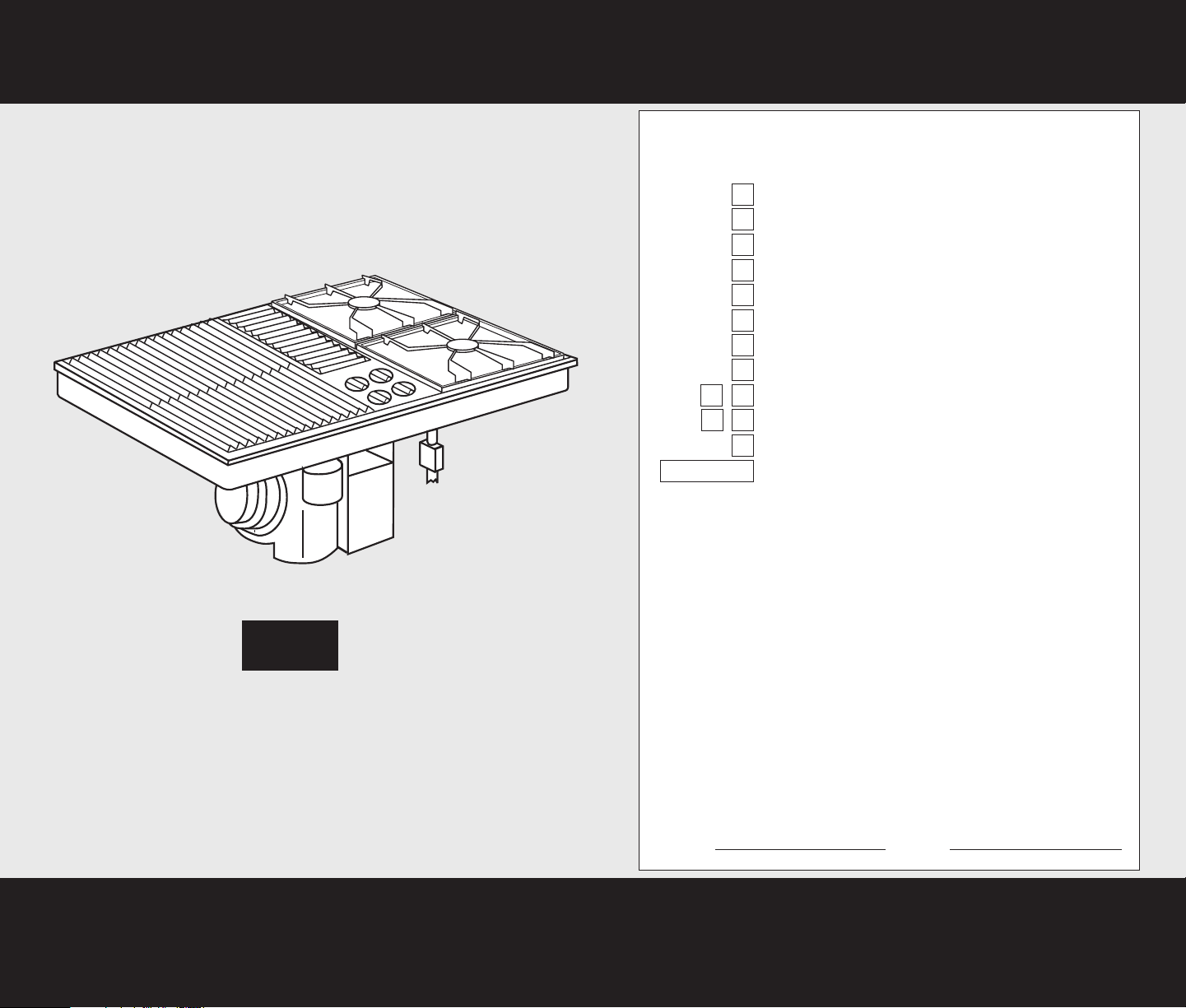
Quick Reference
Table of Contents:
Pages Before you start
Cutout dimensions
Clearance dimensions
Product dimensions
Tools and materials needed
Parts supplied
Electrical requirements
Gas supply requirements
Venting requirements
Installation steps
Gas conversions
Cooktop removal
Need assistance?
Check your Use and Care Guide for a toll-free number to call, or
call the dealer from whom you purchased the cooktop when you:
Have questions about the cooktop installation or operation.
Need to obtain the name and number of an authorized service
company.
The dealer is listed in the Yellow Pages of your phone directory
under “Appliances — Household — Major — Service and Repair.”
When you call, you will need:
The cooktop model number.
The cooktop serial number.
Both numbers are listed on the model/serial rating plate, located
on the bottom of the right side of the downdraft plenum.
Write both numbers down now before installing cooktop.
Model # Serial #
1
1
1
2
2
2
2
3
34
56
7
Back cover
IMPORTANT:
Read and save these instructions.
Installation Instructions
IMPORTANT:
Installer: Leave Installation Instructions with the homeowner.
Homeowner: Keep Installation Instructions for future reference.
Save Installation Instructions for local electrical inspector's use.
Part No.
8101P350-60/
8284676
30" GAS
Downdraft Cooktop
Modules selected at time of purchase.
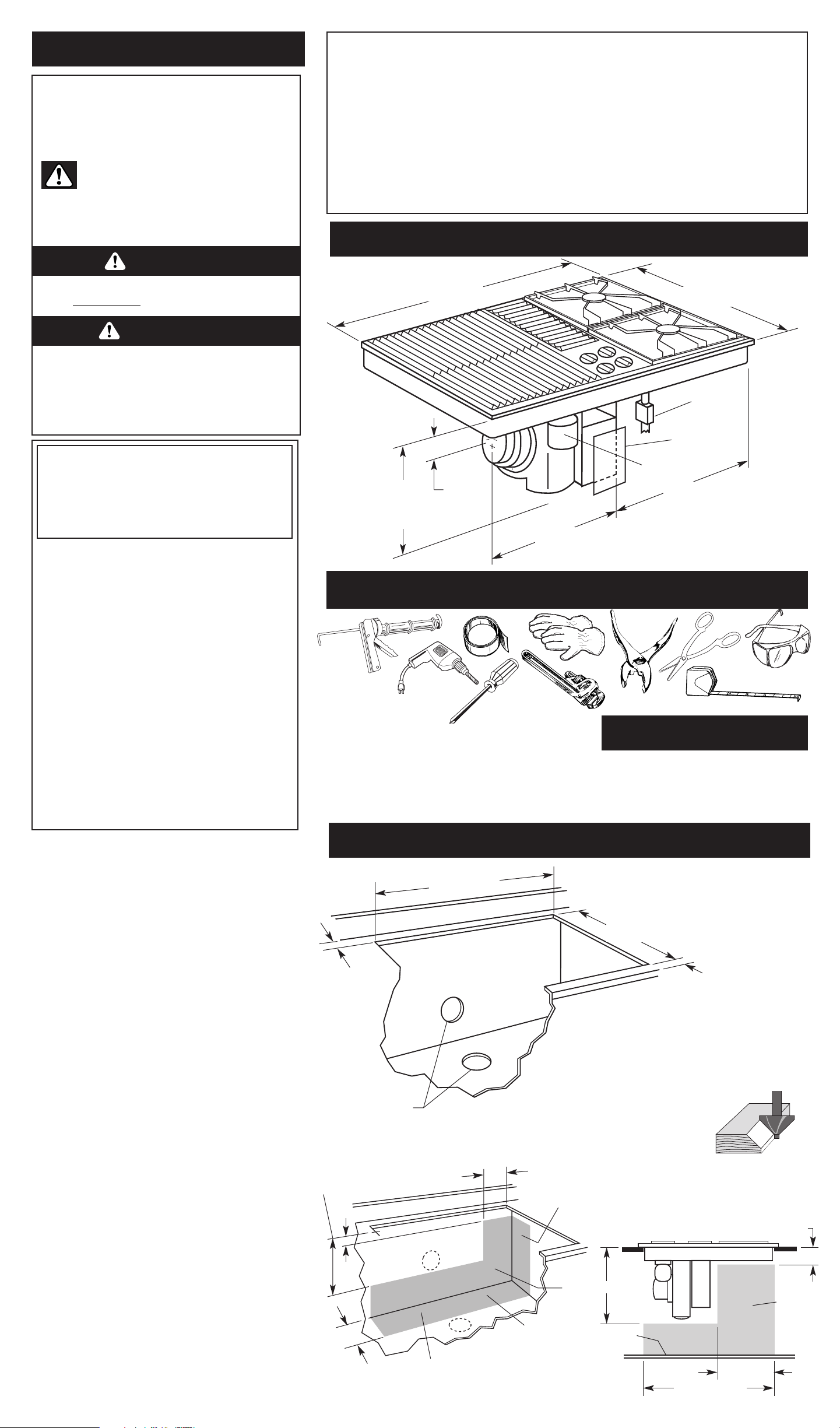
Product dimensions
Parts supplied:
Tools and materials needed:
tape measure
pipe
wrench
metal
snips
duct
tape
pliers
gloves
safety glasses
caulking
gun with
weather-
proof
caulking
Phillips
screwdriver
Blower can be
swiveled 90°.
Not shown:
• gas line shutoff valve
• L.P. gas-resistant pipe-joint compound
• AGA4
or CSA design-certified flexible metal connector
(4-5 feet) (1.2-1.5 m) or rigid gas supply line as needed
• flare union adapter for connection to pressure regulator
(1/2" NPT x 1/2" or 3/4" I.D.)
• wall or roof cap
• metal vent
• 2 sheet metal screws to attach transition vent to venting adapter
Remove parts from packages. Check that
all parts were included.
3-5/16"
(8.4 cm)
burner box
depth
• literature pack
• 4 orifice hoods
• exhaust flow rate tester card
pressure
regulator
wiring box
cover
grease
container
15-5/8"
(39.7 cm)
blower
housing
depth
29-7/8" (75.9 cm)
width
21-1/2" (54.6 cm)
depth
14"
(35.6 cm)
11-7/8"
(30.2 cm)
Minimum base cabinet dimensions —
30" (76.2 cm) base cabinet.
24" (61.0 cm) base cabinet depth
25" (63.5 cm) countertop depth
Cutout preparation:
Decorative laminate —
Chamfer all exposed
edges to prevent chipping laminate.
Cut radius corners and file to insure
smooth edges and to prevent cracking.
Page 1
Cutout dimensions
Before you start...
Important: Observe all governing codes and
ordinances.
Proper installation is your responsibility.
• Make sure you have everything necessary for correct
installation.
• Have a qualified technician install this cooktop.
• Comply with the installation clearances specified on
the model/serial rating plate.
Model/serial rating plate is located on the right side of
the downdraft plenum.
Cooktop location should be away from strong draft
areas, such as windows, doors and strong heating vents
or fans. Locate cooktop for convenient use in kitchen.
Grounded electrical outlet is required. See “Electrical
requirements,” Page 2.
Proper gas supply connection must be available. See
“Gas supply requirements,” Page 3.
Vent system must terminate outdoors.
All openings in the wall or floor where cooktop is to be
installed must be sealed.
When installing a cooktop under existing cabinets and
the installation does not meet the minimum cabinet
clearances, install a range hood above the cooktop to
avoid burn hazards.
It is the customer’s responsibility:
• To contact a qualified electrical installer.
• To assure that electrical installation adequate and in
conformance with National Electrical Code,
ANSI/NFPA 70 — latest edition* and all local codes
and ordinances.
Mobile home installation: The installation of this
cooktop must conform to the Manufactured Home
Construction and Safety Standards, Title 24 CFR, Part
3280 (formerly the Federal Standard for Mobile Home
Construction and Safety; Title 24 HUD part 280); or
when such standard is not applicable, the Standard for
Manufactured Home Installations (Manufactured Home
Sites, Communities and Setups), ANSI A225.1 — latest
edition*, or with local codes.
Copies of the standards listed may be obtained from:
* National Fire Protection Association
One Batterymarch Park
Quincy, Massachusetts 02269
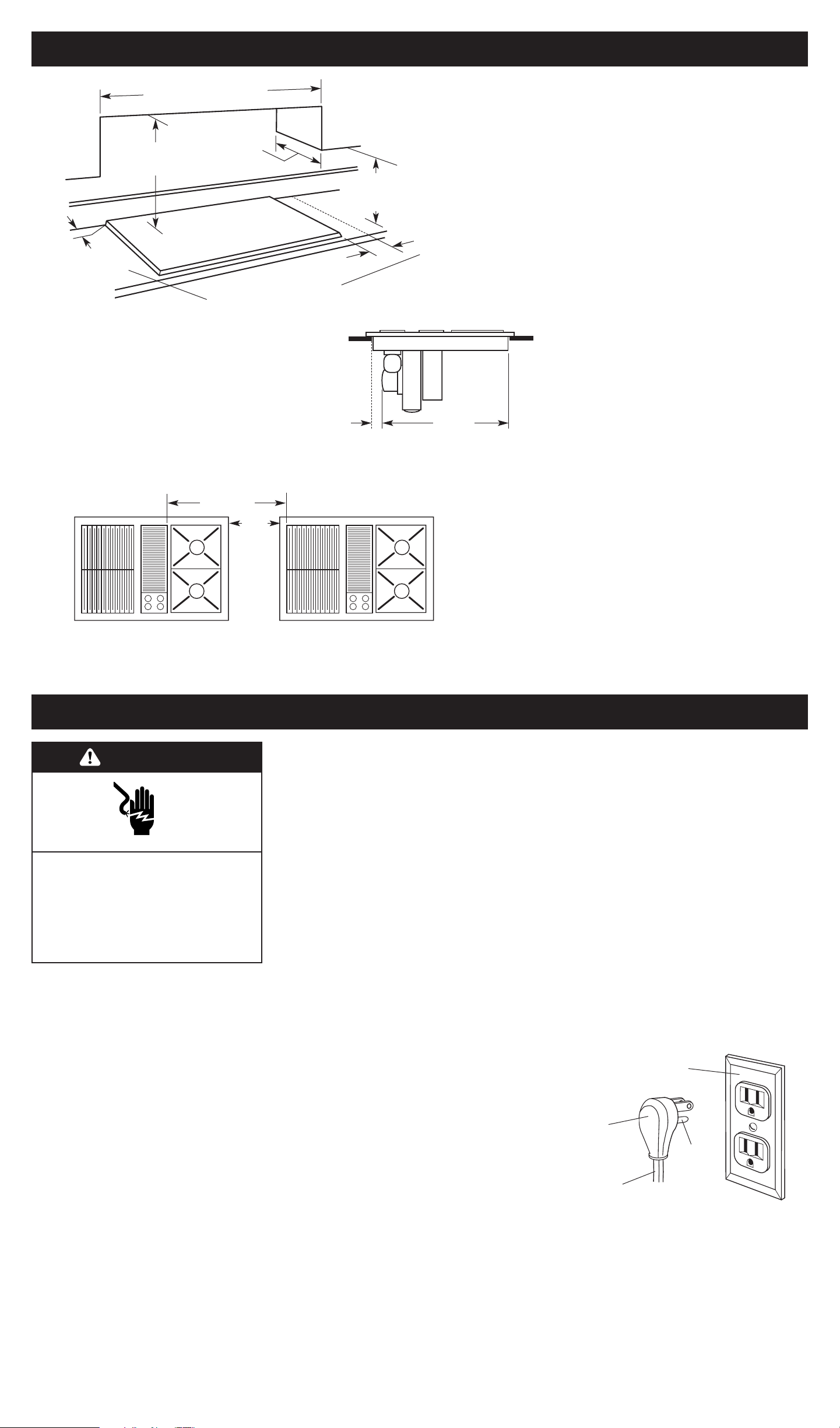
1-7/8" (4.8 cm)
minimum space
to front edge of
countertop
Select required vent
cutout (see page 4
for exhaust vent
cutout location).
Countertop must be
supported within
3" (7.6 cm) of cutout.
28-7/8" (73.3 cm)
cutout width
15/16" (2.4 cm)
minimum
distance to
backsplash or
vertical wall
20-15/16"
(53.2 cm)
cutout depth
16" (40.6 cm)
4" (10.2 cm)
14" (35.6 cm)
11" (27.9 cm)
side wall
rear
wall
cabinet bottom
Install gas line within shaded
area of cabinet.
11" (27.9 cm)
28-7/8" (73.3 cm)
16" (40.6 cm)
4" (10.2 cm)
cabinet
bottom
Install
grounded
electrical
outlet
within
shaded area
of rear wall.
Cabinet drawers under the
cooktop will need to be
removed and the drawer
fronts installed
permanently on front of
cabinet.
Your safety and the safety of
others are very important.
We have provided many important safety
message in this manual and on your appliance.
Always read and obey all safety messages.
WARNING
This is the safety alert symbol.
This symbol alerts you to potential hazards
that can kill or hurt you and others.
All safety messages will be preceded by the
safety alert symbol and the word “DANGER” or
“WARNING”. These words mean:
All safety messages will tell you what the
potential hazard is, tell you how to reduce the
chance of injury, and tell you what can happen if
the instructions are not followed.
You can be killed or seriously injured if you
don’t immediately follow instructions.
You can be killed or seriously injured if you
don’t follow instructions.
D ANGER
WARNING: If the information in this
manual is not followed exactly, a fire
or explosion may result causing
property damage, personal injury or
death.
— Do not store or use gasoline or
other flammable vapors and liquids
in the vicinity of this or any other
appliance.
— WHAT TO DO IF YOU SMELL GAS
• Do not try to light any appliance.
• Do not touch any electrical switch.
• Do not use any phone in your
building.
• Immediately call your gas supplier
from a neighbor’s phone. Follow
the gas supplier’s instructions.
• If you cannot reach your
gas supplier, call the fire
department.
— Installation and service must be
performed by a qualified installer,
service agency or the gas supplier.
WARNING: To reduce the risk of fire,
electric shock, or injury to persons, observe
the following:
Installation work and electrical wiring must
be done by qualified person(s) in
accordance with all applicable codes and
standards, including fire-rated construction.
Sufficient air is needed for proper
combustion and exhausting of gases
through the flue (chimney) of fuel burning
equipment to prevent back drafting. Follow
the heating equipment manufacturer’s
guideline and safety standards such as
those published by the American Society
for Heating, Refrigeration and Air
Conditioning Engineers (ASHRAE), and the
local code authorities.
When cutting or drilling into wall or ceiling,
do not damage electrical wiring and other
hidden utilities.
Ducted fans must always be vented to the
outdoors.
WARNING: To reduce the risk of fire, use
only metal ductwork.
Drill
Page 2
Electrical requirements
A 120-volt, 60-Hz, AC-only, 15- or 20-ampere,
fused electrical supply is required. A time-
delay fuse or circuit breaker is recommended.
It is recommended that a separate circuit
serving only this appliance be provided.
Electronic ignition systems operate within
wide voltage limits, but proper ground and
polarity are necessary. In addition to checking
that the outlet provides 120-volt power and is
correctly grounded, the outlet must be
checked by a qualified electrician to see if it is
wired with correct polarity.
Important: This cooktop is equipped with an
electronic ignition system that will not
operate if plugged into an outlet that is not
properly polarized.
The wiring diagram is located on the inside of
the terminal box cover.
ground
prong
3-prong polarized
ground-type outlet
3-prong
ground plug
power
supply cord
Recommended ground
method
For your personal safety, this cooktop must be
grounded. This appliance is equipped with a
3-prong ground plug. To minimize possible
shock hazard, the cord must be plugged into a
mating 3-prong ground-type outlet, grounded
in accordance with National Electrical Code
ANSI/NFPA 70 — latest edition* and all local
codes and ordinances. If a mating outlet is not
available, it is the personal responsibility and
obligation of the customer to have a properly
polarized and grounded, 3-prong outlet
installed by a qualified electrician.
Copies of the standards listed above may be obtained
from:
* National Fire Protection Association
One Batterymarch Park
Quincy, Massachusetts 02269
Electrical Shock Hazard
Plug into a grounded 3-prong outlet.
Do not remove ground prong.
Do not use an adapter.
Failure to follow these instructions
can result in death, fire, or electrical
shock.
WARNING
If codes permit and a separate ground
wire is used, it is recommended that a
qualified electrician determine that the
ground path is adequate.
Check with a qualified electrician if you
are not sure whether the cooktop is
properly grounded.
Do not ground to a gas pipe.
Clearance dimensions
Spacing for multiple downdraft cooktop installations:
Note: 30" (76.2 cm) minimum when bottom of wood
or metal cabinet is protected by not less than 1/4"
flame retardant millboard covered with not less than
No. 28 MSG sheet steel, 0.015" stainless steel,
0.024" aluminum or 0.020" copper.
36" (91.4 cm) minimum clearance between the top
of the cooking platform and bottom of unprotected
wood or sheet metal.
Do Not seal
cooktop to
countertop.
Minimum distance to nearest
combustible vertical surface extending
18" (45.7 cm) above cooktop
0" (0 cm)
**
See Note**
for minimum
clearances.
18" (45.7 cm)
minimum clearance
upper cabinet
to countertop
2"
(5.1 cm)
Side clearance — 2" (5.1 cm) minimum
clearance is required. 6" (15.2 cm) clearance
between side of cooktop and side wall is
recommended for maximum ventilation
performance.
Rear clearance — The rear edge of the
cooktop may be installed flush with
countertop backsplash. 15/16" (2.4 cm)
clearance between rear edge of appliance and
rear wall is recommended.
Installation location should
provide sufficient room for:
• Removing grease containers.
• Accessing gas regulator.
Minimum spacing shown is required for
satisfactory performance when installing the
downdraft cooktop in combination with one
or more downdraft cooktops.
18" (45.7 cm)
minimum
25-7/8"
(65.7 cm)
2"
(5.1 cm)
min.
motor
blower
clearance
30" (76.2 cm) minimum when
higher than 18" (45.7 cm)
13" (33 cm)
maximum upper
cabinet depth
5-3/8"
(13.7 cm)
minimum
between
cutouts
4-3/8"
(11.1 cm)
minimum
between
cooktops
Motor/blower clearance — 2" (5.1 cm)
clearance is required between motor and
cabinet for proper cooling. 6" (15.2 cm)
clearance is recommended for maximum
performance.
Loading...