


INSTALLATION INSTRUCTIONS
Commercial Washer
INSTRUCTIONS D’INSTALLATION
Laveuse commerciale
TABLE OF CONTENTS
. |
Page |
Washer Safety.......................................................................... |
2 |
Tools & Parts............................................................................. |
3 |
Dimensions............................................................................... |
4 |
Location Requirements........................................................... |
5 |
Drain System............................................................................ |
6 |
Electrical Requirements.......................................................... |
7 |
Installation Instructions........................................................... |
8 |
Connect Drain Hose................................................................. |
9 |
Connect Inlet Hoses.............................................................. |
10 |
Level Washer.......................................................................... |
11 |
Installing Coin Slide and Coin Box....................................... |
11 |
Complete Installation............................................................. |
12 |
Typical Full Load Sizes.......................................................... |
12 |
Washer Maintenance............................................................. |
13 |
If You Need Assistance.......................................................... |
14 |
Alternate Parts & Accessories.............................................. |
14 |
Warranty.................................................................................. |
15 |
TABLE DES MATIÈRES |
|
|
Page |
Sécurité de la laveuse............................................................ |
16 |
Outillage et pièces................................................................. |
17 |
Dimensions............................................................................. |
18 |
Exigences d’emplacement.................................................... |
19 |
Système de vidange............................................................... |
20 |
Spécifications électriques..................................................... |
21 |
Instructions d’installation...................................................... |
22 |
Raccordement du tuyau de vidange.................................... |
23 |
Raccordement des tuyaux d’arrivée d’eau.......................... |
24 |
Établissement de l’aplomb de la laveuse............................ |
25 |
Installation de la glissière et de la boîte à monnaie............ |
25 |
Achever l’installation............................................................. |
26 |
Taille typique des charges complètes.................................. |
26 |
Entretien de la laveuse.......................................................... |
27 |
Si vous avez besoin d’assistance......................................... |
28 |
Pièces supplémentaires et accessoires.............................. |
28 |
Garantie.................................................................................. |
29 |
W10837712A |
|
W10861398A – SP |
www.whirlpoolcommerciallaundry.com |

WASHER SAFETY
2

TOOLS & PARTS
Tools Needed:
|
|
|
|
Level |
Pliers |
Utility Knife |
|
|
|
|
|
|
|
|
|
9/16" (14 mm) |
Flat-Blade Screwdriver |
Open End Wrench |
|
Optional tools:
Flashlight |
Bucket |
Parts Supplied:
|
|
|
|
|
|
|
|
|
|
|
|
|
|
|
|
|
|
|
|
|
|
|
|
|
|
|
|
|
|
|
|
|
|
|
|
|
|
|
|
|
|
|
|
|
|
|
Water Inlet Hoses (2) |
|
Inlet Hose Washers (4) |
Drain Hose with Clamp, |
|||||||||||||||||||||||||||||||||||||||||||
|
|
|
|
|
|
|
|
|
|
|
|
|
|
|
|
|
|
|
|
|
|
|
|
|
|
|
|
|
|
|
|
|
|
|
|
|
|
|
|
|
|
|
|
|
|
U-Form, and Cable Tie |
|
|
|
|
|
|
|
|
|
|
|
|
|
|
|
|
|
|
|
|
|
|
|
|
|
|
|
|
|
|
|
|
|
|
|
|
|
|
|
|
|
|
|
|
|
|
|
Service Door Lock Assembly |
Coin Slide Decal Kit |
(coin slide models only) |
(on some models) |
3
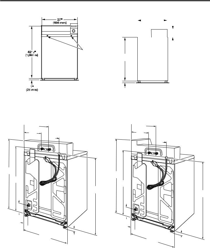
DIMENSIONS
Front View |
Side View |
Back View
Non-coin-operated models
 16"
16"
(406 mm)
101/2"
(267 mm)
421/2"
(1.080 m)
371/4"
(946 mm)
63/4" 
(171 mm)
 41/4"
41/4"
(108 mm)
27"
(686 mm)
Screw locations
51/2"
 (140 mm)
363/4"
(933 mm)
1"
(25 mm)
|
|
27" |
|
|
|
Non-coin-operated |
||||
|
|
|
|
|
|
|
|
|
models: |
|
|
|
|
|
|
|
|
||||
|
(686 mm) |
|
|
|
|
61/4" |
||||
|
|
|||||||||
|
|
|
|
|
|
|
|
|
|
(159 mm) |
|
|
|
|
|
|
|
|
|||
|
|
|
|
|
|
|
|
Coin-operated |
||
|
|
|
|
|
|
|
|
|
|
models: |
|
|
|
|
|
|
|
|
|
81/4" |
|
|
|
|
|
|
|
|||||
|
|
|
|
|
||||||
|
|
|
|
|
|
|
|
|
|
(210 mm) |
|
|
|
|
|
|
|
|
|
|
|
361/4"
(921 mm)
1" (25 mm)
Coin-operated models
 16"
16"
(406 mm)
101/2"
(267 mm)
51/2"
 (140 mm)
441/2"
(1.130 m)
371/4"
(946 mm)
363/4"
(933 mm)
63/4" 
(171 mm)
 41/4"
41/4"
(108 mm)
27" |
|
|
|
1" |
|||
(686 mm) |
|||
(25 mm) |
|||
|
|||
4

LOCATION REQUIREMENTS
Selecting the proper location for your washer improves performance and minimizes noise and possible washer “walk.”
Your washer can be installed in a basement, laundry room, or recessed area. See “Drain System.”
Companion appliance location requirements should also be considered.
IMPORTANT: Do not install or store the washer where it will be exposed to the weather. Do not store or operate the washer in temperatures at or below 32°F (0°C). Some water can remain in the washer and can cause damage in low temperatures. Proper installation is your responsibility.
You will need:
nA water heater set to 120°F (49°C).
nA grounded electrical outlet located within 4 ft. (1.2 m) of power cord on back of washer. See “Electrical Requirements.”
nHot and cold water faucets located within 4 ft. (1.2 m) of hot and cold water fill valves on washer, and water pressure of 20-100 psi (138-690 kPa). A pressure reduction valve should be used in the supply line where inlet pressure entering the building exceeds 100 PSI (690 kPa) to avoid damage to the washer mixing valve.
nSingle washer installations require 12" (300 mm) minimum risers to provide an air cushion and avoid noise and damage to valves.
nA level floor with maximum slope of 1" (25 mm) under entire washer. Installing on carpet is not recommended.
nFloor must support washer’s total weight (with water and load) of 315 lbs (143 kgs).
nA floor drain under the bulkhead. Prefabricated bulkheads with electrical outlets, water inlet lines, and drain facilities should be used only where local codes permit.
Recessed Area or Closet Installation
This washer may be installed in a recessed area or closet. The installation dimensions shown are the minimum spaces
allowable. Additional spacing should be considered for ease of installation and servicing. Companion appliance spacing should be considered.
Minimum installation spacing
5
 Loading...