


Cabrio WTW6400S
Whirlpool Cabrio WTW6400S, Cabrio WTW6600S, Cabrio WTW6400SW, Cabrio WTW6600SW, Cabrio WTW6600SG Technical Manual
...
L-80
JOB AID
Part No. 8178582
AUTOMATIC
WASHER
WITH 6TH SENSE
™
TECHNOLOGY
CONSUMER CARE TECHNICAL
EDUCATION GROUP PRESENTS
MODELS: WTW6400S & WTW6600S

FORWARD
This Whirlpool Job Aid, “Cabrio™ Automatic Washer With 6th Sense™ Technology” (Part No.8178582),
provides the In-Home Service Professional with information on the installation, operation, and
service of the Cabrio
™
Automatic Washer With 6th Sense™ Technology. For specific information
on the model being serviced, refer to the “Use and Care Guide,” or “Tech Sheet” provided with
the washer.
The Wiring Diagram used in this Job Aid is typical and should be used for training purposes only.
Always use the Wiring Diagram supplied with the product when servicing the unit.
GOALS AND OBJECTIVES
The goal of this Job Aid is to provide information that will enable the In-Home Service Professional
™
to properly diagnose malfunctions and repair the Cabrio
Technology.
The objectives of this Job Aid are to:
• Understand and follow proper safety precautions.
• Successfully troubleshoot and diagnose malfunctions.
• Successfully perform necessary repairs.
• Successfully return the washer to its proper operational status.
Automatic Washer With 6th Sense™
WHIRLPOOL CORPORATION assumes no responsibility for any repairs made on
our products by anyone other than authorized In-Home Service Professionals.
Copyright © 2006, Whirlpool Corporation, Benton Harbor, MI 49022
- ii -

TABLE OF CONTENTS
Page
GENERAL . . . . . . . . . . . . . . . . . . . . . . . . . . . . . . . . . . . . . . . . . . . . . . . . . . . . . . . . . . . . . . 1-1
Washer Safety . . . . . . . . . . . . . . . . . . . . . . . . . . . . . . . . . . . . . . . . . . . . . . . . . . . . . . . . . .
Model & Serial Number Designations . . . . . . . . . . . . . . . . . . . . . . . . . . . . . . . . . . . . . . . . 1-2
Model & Serial Number Label & Tech Sheet Locations . . . . . . . . . . . . . . . . . . . . . . . . . . .
Specifications . . . . . . . . . . . . . . . . . . . . . . . . . . . . . . . . . . . . . . . . . . . . . . . . . . . . . . . . . . 1-4
Impeller Wash Program/Selectability . . . . . . . . . . . . . . . . . . . . . . . . . . . . . . . . . . . . . . . . .
1-1
1-3
1-6
INSTALLATION INFORMATION
Installation Requirements . . . . . . . . . . . . . . . . . . . . . . . . . . . . . . . . . . . . . . . . . . . . . . . . . 2-1
Installation Instructions . . . . . . . . . . . . . . . . . . . . . . . . . . . . . . . . . . . . . . . . . . . . . . . . . . . 2-5
PRODUCT OPERATION
Theory Of Operation
Washer Use . . . . . . . . . . . . . . . . . . . . . . . . . . . . . . . . . . . . . . . . . . . . . . . . . . . . . . . . . . . .
Washer Care . . . . . . . . . . . . . . . . . . . . . . . . . . . . . . . . . . . . . . . . . . . . . . . . . . . . . . . . . .
Troubleshooting . . . . . . . . . . . . . . . . . . . . . . . . . . . . . . . . . . . . . . . . . . . . . . . . . . . . . . . .
COMPONENT ACCESS
Component Locations . . . . . . . . . . . . . . . . . . . . . . . . . . . . . . . . . . . . . . . . . . . . . . . . . . . . 4-1
Removing The Encoder And The User Interface Board
Removing The Water Inlet/Dispenser Valve Assembly, Power Supply Cord,
And Machine/Motor Control & Pressure Transducer . . . . . . . . . . . . . . . . . . . . . . . . . . .
Removing A Dispenser, The Fresh Fill Inlet Valve, And The Lid Lock . . . . . . . . . . . . . . . .
Removing The Lid And A Hinge . . . . . . . . . . . . . . . . . . . . . . . . . . . . . . . . . . . . . . . . . . . . .
Removing The Basket, Basket Hub, & Lint Filter
Removing The Drain And Recirculation Pumps
Removing The Drive Motor & Rotor Position Sensor
Removing The Tub
Accessing The Pressure Transducer Tubing, Recirculation Tube,
And Drain Pump Harness
. . . . . . . . . . . . . . . . . . . . . . . . . . . . . . . . . . . . . . . . . . . . . . . . . . . 3-1
. . . . . . . . . . . . . . . . . . . . . . . . . . . . . . . . . . . . . . . . . . . . . . . . . . . . . 3-1
. . . . . . . . . . . . . . . . . . . . . . . . . . . . . . . . . . . . . . . . . . . . . . . . . . . 4-1
. . . . . . . . . . . . . . . . . . . . . . . . . . . . . . . . . . . . . . . . . . . . . . . . . . . . . 4-16
. . . . . . . . . . . . . . . . . . . . . . . . . . . . . . . . . . . . . . . . . . . . . 2-1
3-3
3-12
3-14
. . . . . . . . . . . . . . . . . . . . . . . . . . 4-2
4-4
4-6
4-9
. . . . . . . . . . . . . . . . . . . . . . . . . . . . . . 4-10
. . . . . . . . . . . . . . . . . . . . . . . . . . . . . . . 4-12
. . . . . . . . . . . . . . . . . . . . . . . . . . . 4-14
. . . . . . . . . . . . . . . . . . . . . . . . . . . . . . . . . . . . . . . . . . . . . . 4-18
COMPONENT TESTING . . . . . . . . . . . . . . . . . . . . . . . . . . . . . . . . . . . . . . . . . . . . . . . . . . . 5-1
Water Inlet/Dispenser Valve Assembly
Drain Pump . . . . . . . . . . . . . . . . . . . . . . . . . . . . . . . . . . . . . . . . . . . . . . . . . . . . . . . . . . . . 5-2
Recirculation Pump . . . . . . . . . . . . . . . . . . . . . . . . . . . . . . . . . . . . . . . . . . . . . . . . . . . . . . 5-2
Lid Lock . . . . . . . . . . . . . . . . . . . . . . . . . . . . . . . . . . . . . . . . . . . . . . . . . . . . . . . . . . . . . . . 5-3
Drive Motor Stator . . . . . . . . . . . . . . . . . . . . . . . . . . . . . . . . . . . . . . . . . . . . . . . . . . . . . . . 5-4
DIAGNOSTICS & TROUBLESHOOTING . . . . . . . . . . . . . . . . . . . . . . . . . . . . . . . . . . . . . . 6-1
Display Fault/Error Codes . . . . . . . . . . . . . . . . . . . . . . . . . . . . . . . . . . . . . . . . . . . . . . . . . 6-1
Diagnostic Guide . . . . . . . . . . . . . . . . . . . . . . . . . . . . . . . . . . . . . . . . . . . . . . . . . . . . . . . . 6-4
Diagnostic Tests
Troubleshooting Guide
Troubleshooting Tests
Accessing & Removing The Electronic Assemblies . . . . . . . . . . . . . . . . . . . . . . . . . . . . .
WIRING DIAGRAM . . . . . . . . . . . . . . . . . . . . . . . . . . . . . . . . . . . . . . . . . . . . . . . . . . . . . . . 7-1
. . . . . . . . . . . . . . . . . . . . . . . . . . . . . . . . . . . . . . . . . . . . . . . . . . . . . . . . 6-4
. . . . . . . . . . . . . . . . . . . . . . . . . . . . . . . . . . . . . . . . . . . . . . . . . . . 6-9
. . . . . . . . . . . . . . . . . . . . . . . . . . . . . . . . . . . . . . . . . . . . . . . . . . . . 6-9
. . . . . . . . . . . . . . . . . . . . . . . . . . . . . . . . . . . . . . . 5-1
6-15
- iii -

— NOTES —
- iv -

GENERAL
DANGER
WARNING
WASHER SAFETY
Your safety and the safety of others are very important.
We have provided many important safety messages in this manual and on your appliance.
Always read and obey all safety messages.
This is the safety alert symbol.
This symbol alerts you to potential hazards that can kill or hurt you and others.
All safety messages will follow the safety alert symbol and either the word
“DANGER” or “WARNING.” These words mean:
You can be killed or seriously injured if you don’t
immediately follow instructions.
You can be killed or seriously injured if you don’t
follow instructions.
All safety messages will tell you what the potential hazard is, tell you how to reduce the
chance of injury, and tell you what can happen if the instructions are not followed.
1-1

MODEL & SERIAL NUMBER DESIGNATIONS
MODEL NUMBER
MODEL NUMBER W T W 6 6 00 S W 0
BRAND
W = Whirlpool
E = Estate
R = Roper
I = Inglis
ACCESS / FUEL
T = Top Load G = Gas
F = Front Load H = Horizontal
W = Work Space V = Vertical
E = Electric
PRODUCT
W = Washer P = Pedestal
D = Dryer B = Combo
T = Thin Twin C = Compact
SERIES
1 = Innovation 6 = Oasis
2 = Commercial 7 = Merloni
3 = Compact 8 = Horizon
4 = Stack 9 = Duet/Combo
5 = LEAP
PRICE POINT LEVELS (1 - 7)
TRADE PARTNER
00 = Brand 30 = NATM
10 = SBC 40 = Lowe’s
20 = Best Buy
YEAR OF INTRODUCTION
S = 2006
T = 2007
COLOR CODE
W = White w/Silver Metallic Console
G = Biscuit w/Gold Metallic Console
B = Black w/Black Metallic Console
ENGINEERING CHANGE
0 = Basic Original Release
1 = First Revision
SERIAL NUMBER
SERIAL NUMBER C T 41 10200
MANUFACTURING SITE
C = Clyde, OH
YEAR OF PRODUCTION
T = 2006
WEEK OF PRODUCTION
41 = 41st Week
PRODUCT SEQUENCE NUMBER
1-2

MODEL & SERIAL NUMBER LABEL &
TECH SHEET LOCATIONS
The Model/Serial Number Label and Tech Sheet locations are shown below.
Model/Serial Number Location
Tech Sheet Location
(Access Under Cabinet Top)
1-3

SPECIFICATIONS
MODEL NUMBERS WTW6400SW WTW6600SW, G, B
PRIMARY FEATURES
CAPACITY (IEC) 4.5 CU FT 4.5 CU FT
USABLE CAPACITY 18 LBS (8.16 KG) 18 LBS (8.16 KG)
MAX SPIN SPEED 950 1000
EXTERIOR
LID FINISH PORCELAIN POWDER COAT
LID SOLID GLASS
TOP FINISH PORCELAIN PORCELAIN
AGITATOR --- -- WASHPLATE IMPELLER IMPELLER
SOUND PACK Q. WASH PLUS Q. WASH ULTRA
TUB WRAP NO YES
MASTIC (FRONT) 1 - 4 X 12 PIECE 1 - 4 X 12 PIECE
CABINET PAD YES YES
LID SEALS NO YES
MAIN DRIVE MOTOR BRUSHLESS PERM MAGNET BRUSHLESS PERM MAGNET
DISPENSERS
MAIN DETERGENT YES YES
TYPE FLUSH FLUSH
CAPACITY 2/3 CUP 2/3 CUP
BLEACH YES YES
TYPE FLUSH/TIMED FLUSH/TIMED
CAPACITY 1 CUP 1 CUP
FABRIC SOFTENER YES YES
TYPE FLUSH/TIMED FLUSH/TIMED
CAPACITY 1/2 CUP 1/2 CUP
CYCLE DEFINITIONS
# OF CYCLES
WHITEST WHITES
DELICATES/HANDWASH
PERM PRESS / CASUAL
SHEETS/TOWELS
DARKS / COLORS
DELAY START
10
HEAVY DUTY
NORMAL
QUICK WASH
BULKY
WOOL
—
—
RINSE / SPIN
DRAIN / SPIN
CLEAN WASHER
11
HEAVY DUTY
NORMAL
WHITEST WHITES
DELICATES/HANDWASH
PERM PRESS / CASUAL
SHEETS/TOWELS
DARKS / COLORS
QUICK WASH
BULKY
WOOL
SOAK
YES -10 HOURS
RINSE / SPIN
DRAIN / SPIN
CLEAN WASHER
OPTIONS
FINAL SPIN SPEEDS SELECTABLE (3) L, M, H SELECTABLE (4) NO SPIN, L, M, H
SOAK PRE SOAK PRE SOAK
CATALYST OPTIONS
DEEP CLEAN
EXTRA RINSE
1-4
DEEP CLEAN
EXTRA RINSE

MODEL NUMBERS WTW6400SW WTW6600SW, G, B
SECONDARY
EOC OFF / SOFT / LOUD OFF / SOFT / LOUD
TIME REMAINING YES YES
TEMPS 5 - 4 ATC 5 - 4 ATC
ATC TEMPS H/C , W/W, W/C, C/C H/C , W/W, W/C, C/C
AUTO WATER LEVEL YES YES
WATER LEVELS
SOIL LEVELS 4 4
STATUS LED’S
ADDITIONAL INFORMATION
COLORS WHITE WHITE / BISCUIT / BLACK
SIZE ( W X D X H ) 28 X 27 X 42 IN (71.2 x 68.5 X 106.6 CM) 28 X 27 X 42 IN (71.2 x 68.5 X 106.6 CM)
WEIGHT (IN CARTON) 165 LBS (74.8 KG) 165 LBS (74.8 KG)
AUTO - NON SELECTABLE MIN. LEVEL = 3.5
(9 CM) ABOVE BASKET BOTTOM
WASH (4) / STATUS (3)
SOAK
WASHING
RINSING
SPIN
DONE
ADD-A-GARMENT
LID LOCKED
AUTO - NON SELECTABLE MIN. LEVEL =
˝
3.5˝ (9 CM) ABOVE BASKET BOTTOM
WASH (4) / STATUS (3)
SOAK
WASHING
RINSING
SPIN
DONE
ADD-A-GARMENT
LID LOCKED
1-5

IMPELLER WASH PROGRAM / SELECTABILITY
WTW 6400S
D = Default Setting
x = Selectable Setting
o = Not Selectable
1-6

WTW 6600S
D = Default Setting
x = Selectable Setting
o = Not Selectable
1-7

— NOTES —
1-8

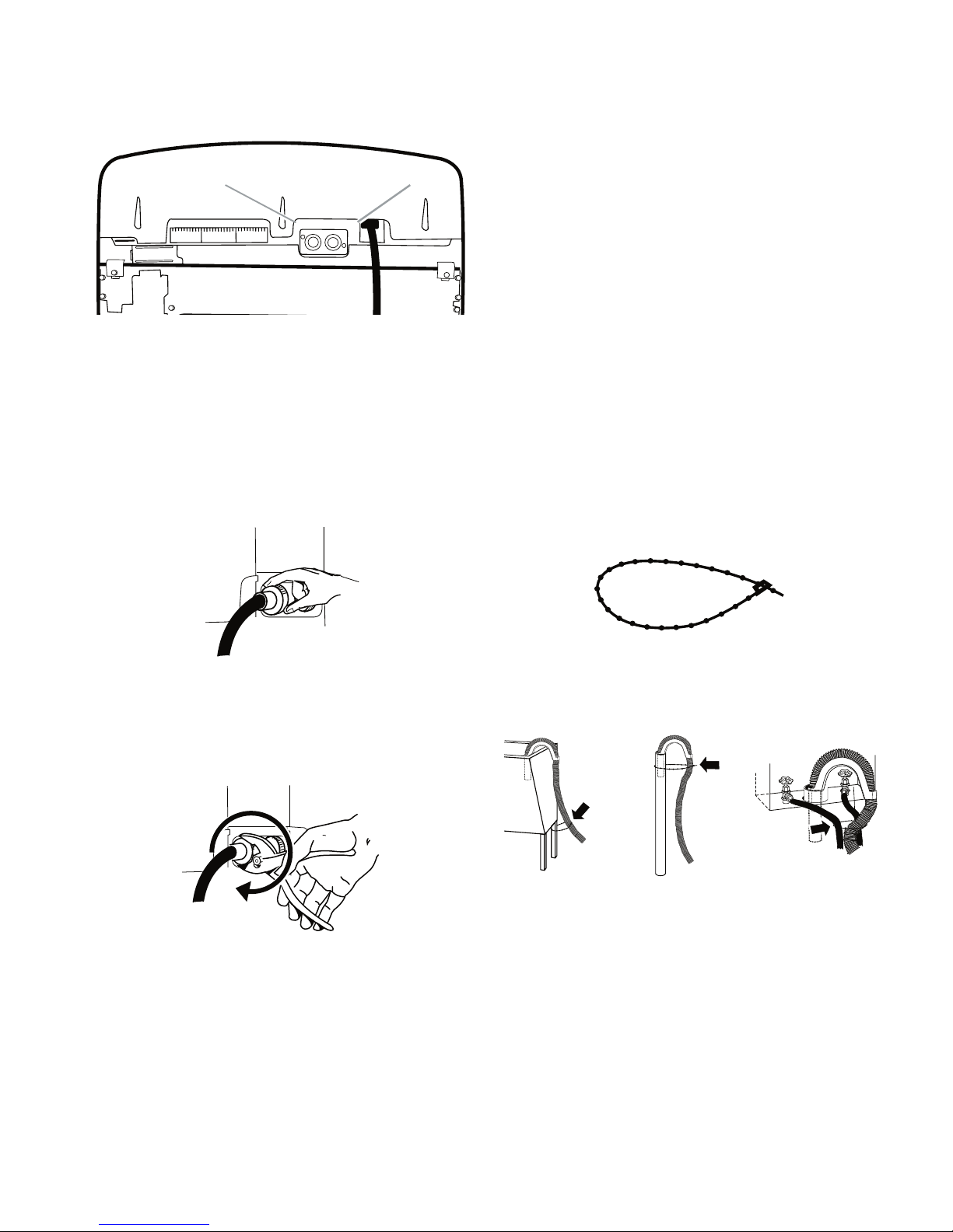
INSTALLATION INFORMATION
A. Drain hose form
B. Water inlet hoses (2
)
C. Flat water inlet hose washers (4
)
D. Beaded tie stra
p
A B
C
D
If You Have: You Will Need to Buy:
Laundry tub or
standpipe taller
than 96˝ (2.4 m)
Sump pump system (if not already
available)
1˝ (2.5 cm)
diameter
standpip
e
2˝ (5 cm) diameter to 1˝ (2.5 cm)
diameter standpipe adapter,
Part Number 3363920 and
connector kit
Part Number 285835
Overhead sewer Standard 20 gal. (76 L) 39˝ (99 cm) tall
drain tub or utility sink, sump pump and
connectors (available from local
plumbing su
ppliers)
Floor drain Siphon break, Part Number 285834;
additional drain hose,
Part Number 8318155 and connector
kit, Part
Number 285835
Water faucets
beyond reach of
fill hose
s
2 longer water fill
hoses:
6 ft (1.8 m) Part Number 76314,
10 ft (3.0 m) Part Number 350008
Lint clogged drain Drain protector, Part Number 367031
INSTALLATION REQUIREMENTS
TOOLS AND PARTS
Gather the required tools and parts before
starting installation. The parts supplied are in
the washer basket.
Tools needed for connecting the drain
hose and water inlet hoses:
Pliers that open to 1-9/16˝ (3.95 cm)
•
Flashlight (optional)
•
Parts Supplied:
Alternate Parts
Tools needed for securing the drain hose
and leveling the washer:
Adjustable or open end wrench 9/16˝
•
(14 mm)
Level
•
•
Wood block
Ruler or measuring tape
•
2-1

LOCATION REQUIREMENTS
A. Front view
B. Side view
C. Closet door with vents
A
B
C
17"*
(43.2 cm)
1"
(2.5 cm)
1"
(2.5 cm)
27-1/2
"
(69.9 cm)
1"*
(2.5 cm)
27"
(68.6 cm)
5"*
(12.7 cm)
14"* max.
(35.6 cm)
3"*
(7.6 cm)
3"*
(7.6 cm)
24 in. *
(155 cm )
2
2
48 in. *
(310 cm )
2
2
Selecting the proper location for your washer
improves performance and minimizes noise
and possible washer “walk.”
The washer can be installed in a basement,
laundry room, closet, or recessed area. See
“Drain System,” page 2-3.
IMPORTANT: Do not install or store the washer where it will be exposed to the weather.
Proper installation is your responsibility.
You will need:
•
A water heater set to deliver 120°F (49°C)
water to the washer.
•
A grounded electrical outlet located with
in 4 ft (1.2 m) of where the power cord is
attached to the back of the washer. See
“Electrical Requirements.”
Hot and cold water faucets located within
•
3 ft (90 cm) of the hot and cold water fill
valves, and water pressure of 20-100 psi
(138-690 kPa) for best performance.
A level floor with a maximum slope of
•
1˝(2.5 cm) under entire washer. Installing the washer on carpeting is not recom
mended.
A sturdy floor to support the washer
•
weight (washer, water and load) of 315 lbs
(143 kgs).
Do not store or operate your washer in tem
peratures at or below 32°F (0°C). Some wa
ter can remain in the washer and can cause
damage in low temperatures.
INSTALLATION SPACING FOR RECESSED
AREA AND CLOSET INSTALLATIONS
The following spacing dimensions are rec
ommended for this washer. This washer has
been tested for installation with spacing of 0
(0 cm) clearance on the sides. Recommend
ed spacing should be considered for the fol
lowing reasons:
Additional spacing should be considered
•
for ease of installation and servicing.
Additional spacing should be considered
•
on all sides of the washer to reduce noise
transfer.
For closet installation with a door, minimum
•
-
ventilation openings in the top and bottom
of the door are required. Louvered doors
with equivalent ventilation openings are
acceptable.
Companion appliance spacing should also
•
be considered.
-
-
-
* Required spacing
-
˝
-
-
2-2
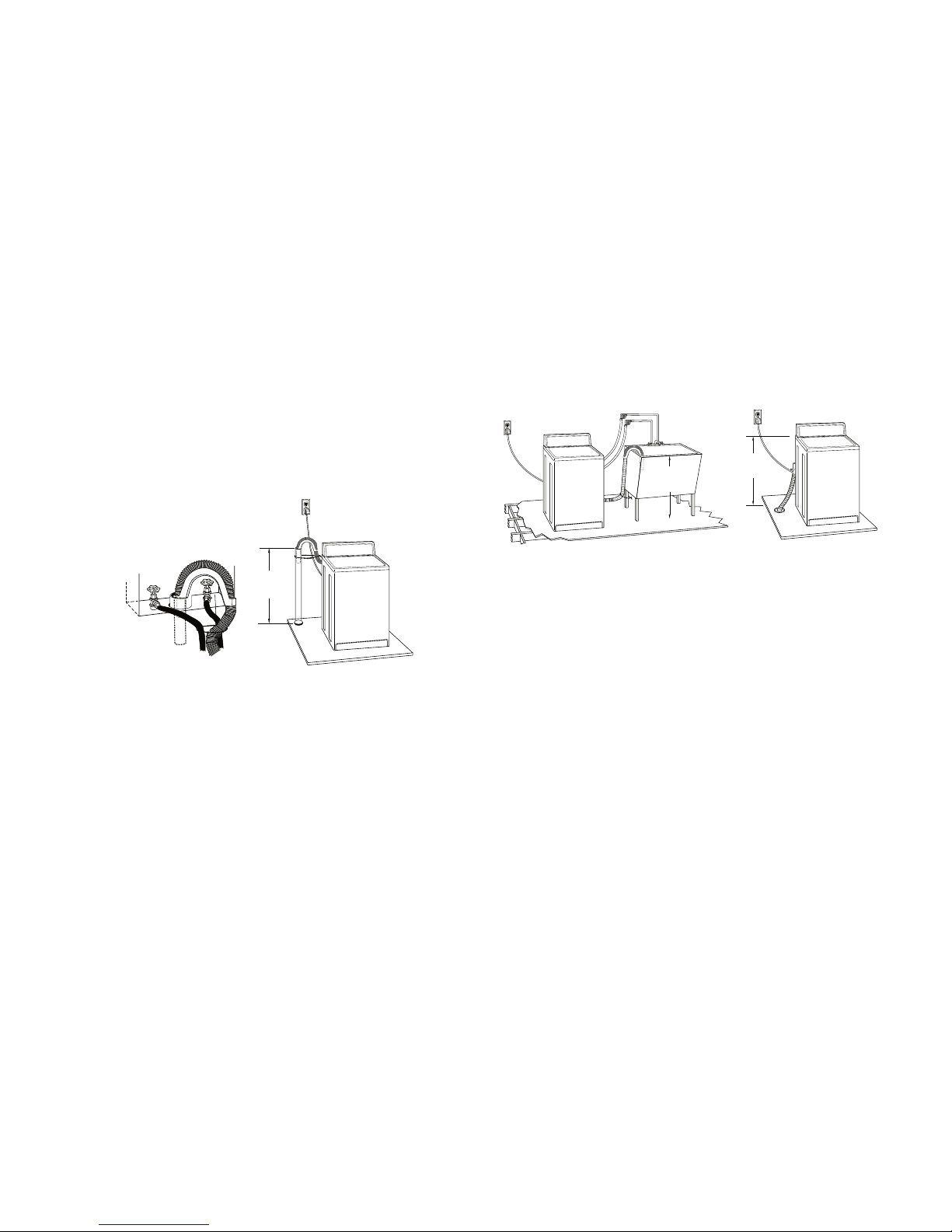
DRAIN SYSTEM
A
B
(99 cm)
39"
C
D
39"
(99 cm)
28"
(71 cm)
The washer can be installed using the standpipe drain system (floor or wall), the laundry
tub drain system, or the floor drain system.
Select the drain hose installation method you
need. See “Tools and Parts,” page 2-1.
LAUNDRY TUB DRAIN SYSTEM (VIEW C)
The laundry tub needs a minimum 20 gal.
(76 L) capacity. The top of the laundry tub
must be at least 39
and no higher than 96
˝ (99 cm) above the floor
˝ (244 cm) from the
bottom of the washer.
STANDPIPE DRAIN SYSTEM—WALL OR
FLOOR (VIEWS A & B)
The standpipe drain requires a minimum diameter standpipe of 2
˝ (5 cm). The minimum
carry-away capacity can be no less than 17
gal. (64 L) per minute. A 2
˝ (5 cm) diameter to
1˝ (2.5 cm) diameter standpipe adapter kit is
available. See “Tools and Parts,” page 2-1.
The top of the standpipe must be at least 39
(99 cm) high and no higher than 96
˝ (244 cm)
˝
from the bottom of the washer.
FLOOR DRAIN SYSTEM (VIEW D)
The floor drain system requires a siphon break
that may be purchased separately. See “Tools
and Parts,” page 2-1.
The siphon break must be a minimum of 28˝
(71 cm) from the bottom of the washer. Addi
tional hoses might be needed.
-
2-3
ELECTRICAL REQUIREMENTS
WARNING
Electrical Shock Hazard
Plug into a grounded 3 prong outlet.
Do not remove ground prong.
Do not use an adapter.
Do not use an extension cord.
Failure to follow these instructions can
result in death, fire, or electrical shock.
A 120 volt, 60 Hz., AC only, 15- or 20-
•
amp, fused electrical supply is required. A
time-delay fuse or circuit breaker is recom
mended. It is recommended that a sepa
rate circuit serving only this appliance be
provided.
This washer is equipped with a power sup-
•
ply cord having a 3 prong grounding plug.
To minimize possible shock hazard, the
•
cord must be plugged into a mating, 3
prong, grounding-type outlet, grounded
in accordance with local codes and ordinances. If a mating outlet is not available,
it is the personal responsibility and obli
gation of the customer to have the prop
erly grounded outlet installed by a qualified
electrician.
GROUNDING INSTRUCTIONS
For a grounded, cord-connected washer:
This washer must be grounded. In the event
of a malfunction or breakdown, grounding
will reduce the risk of electrical shock by
providing a path of least resistance for electric current. This washer is equipped with a
cord having an equipment-grounding con
ductor and a grounding plug. The plug must
be plugged into an appropriate outlet that
is properly installed and grounded in accordance with all local codes and ordinances.
WARNING: Improper connection of the
equipment-grounding conductor can result
in a risk of electric shock. Check with a qualified electrician or serviceman if you are in
doubt as to whether the appliance is properly
-
-
-
-
grounded.
Do not modify the plug provided with the
appliance—if it will not fit the outlet, have a
proper outlet installed by a qualified electri
cian.
For a permanently connected washer:
This washer must be connected to a ground
ed metal, permanent wiring system, or an
equipment-grounding conductor must be
run with the circuit conductors and connected to the equipment-grounding terminal or
lead on the appliance.
-
-
-
If codes permit and a separate ground wire
•
is used, it is recommended that a qualified
electrician determine that the ground path
is adequate.
Do not ground to a gas pipe.
•
Check with a qualified electrician if you are
•
not sure the washer is properly grounded.
Do not have a fuse in the neutral or ground
•
circuit.
2-4
INSTALLATION INSTRUCTIONS
WARNING
Excessive Weight Hazard
Use two or more people to move and
install washer.
Failure to do so can result in back or
other injury.
NOTE: To avoid floor damage, set the washer
onto cardboard before moving across floor.
IMPORTANT:
•
Be sure the foam shipping base has been
removed from the bottom of the washer as
directed in the Unpacking Instructions.
If foam shipping base has not been re-
•
moved, be sure lid is secured with tape be
fore laying washer on its back.
Removing the foam shipping base is nec-
•
essary for proper operation.
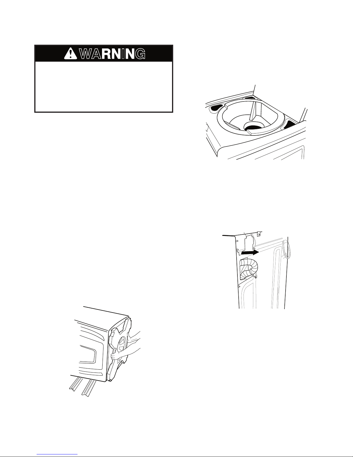
REMOVE SHIPPING BASE
AND PACKING RING
5. Remove tape from lid. Open lid and remove foam packing ring from washer tub.
Keep foam packing ring in case you need
to move the washer in the future.
CONNECT THE DRAIN HOSE
Proper connection of the drain hose protects
your floors from damage due to water leak
age. Read and follow these instructions.
The drain hose is connected to your washer
and is stored inside the washer cabinet.
-
1. Place cardboard supports from shipping
carton on floor behind washer for sup
port.
2. Using 2 or more people, tip the washer
onto its back and place on cardboard
supports.
3. Remove foam shipping base.
4. Set washer upright.
-
2-5
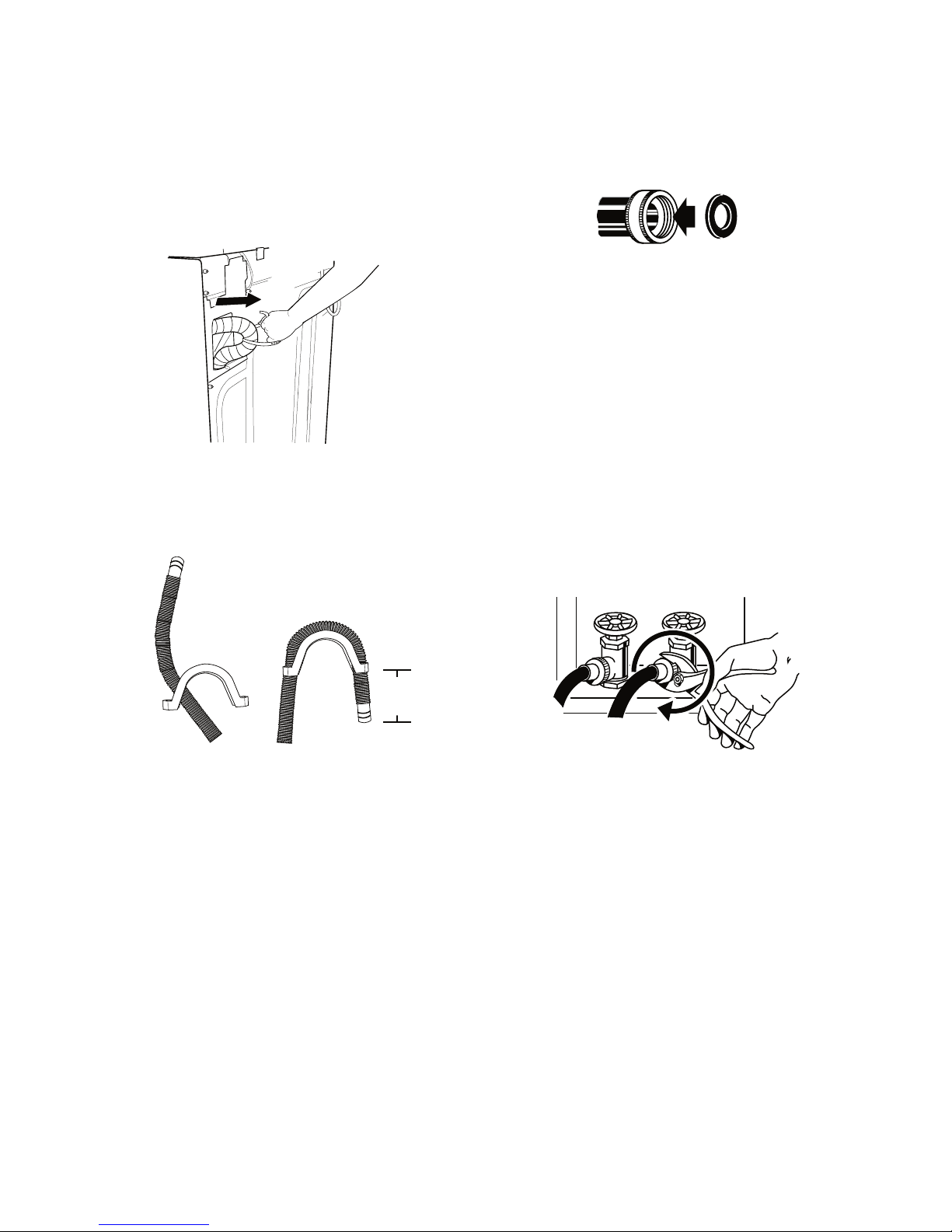
REMOVE DRAIN HOSE
A. Coupling
B. Washer
A B
A B
A
. Feed end of drain hose into one end of form. Secure the lip of the
form into one of the hose ribs.
B. Bend the hose over the top of the form and feed into the other en
d
of the form, extending it 6-8˝ (15.2 cm - 20.3 cm) beyond the form.
Secure the lip of form into one of the hose ribs.
6 - 8˝
(15.2 cm
-
20.3 cm
)
Tighten the couplings with an additional two-thirds turn.
FROM WASHER CABINET
Pull the corrugated drain hose out of the
washer by first grabbing the pull tie. Continue
to pull the hose until the end emerges. Do not
force excess drain hose back into the rear of
the washer.
LAUNDRY TUB DRAIN
OR STANDPIPE DRAIN
Connecting the drain hose form to the cor
rugated drain hose
CONNECT THE INLET HOSES
1. Insert new flat washers (supplied) into
each end of the inlet hoses. Firmly seat
the washers in the couplings.
CONNECT THE INLET HOSES TO
THE WATER FAUCETS
Make sure the washer basket is empty.
2. Attach the hose labeled hot to the hot
water faucet. Screw on coupling by hand
until it is seated on the washer.
3. Attach the hose labeled cold to the cold
water faucet. Screw on coupling by hand
-
until it is seated on the washer.
4. Using pliers, tighten the couplings with
an additional two-thirds turn.
To keep drain water from going back into
the washer:
Do not force excess drain hose into stand-
•
pipe. Hose should be secure but loose
enough to provide a gap for air.
Do not lay excess hose on the bottom of
•
the laundry tub.
FLOOR DRAIN
Do not install the drain hose form on to the
corrugated drain hose. You may need addi
tional parts. See Floor drain under “Tools and
Parts,” page 2-1.
NOTE: Do not overtighten or use tape or sealants on the valve. Damage to the valves can
result.
Clear the water lines
Run water through both faucets and inlet
•
hoses, into a laundry tub, drainpipe or buck
et, to get rid of particles in the water lines
that might clog the inlet valve screens.
Check the temperature of the water to
•
make sure that the hot water hose is con
nected to the hot water faucet and that the
cold water hose is connected to the cold
-
water faucet.
2-6
-
-
CONNECT THE INLET HOSES
COLD
HOT
A. Hot water inlet valve
B. Cold water inlet valve
HO
T
COL
D
A
B
COLD
HO
T
Beaded tie strap
CBA
TO THE WASHER
1. Attach the hot water hose to the inlet
valve labeled hot.
2. Attaching one hose coupling first makes
it easier to tighten the connection with pli
ers.
Check for leaks
Turn on the water faucets and check for
•
leaks. A small amount of water might en
ter the washer. You will drain this in a later
step.
NOTE: Replace inlet hoses after 5 years of
use to reduce the risk of hose failure. Record
hose installation or replacement dates for fu
ture reference.
If you connect only one water hose, you
•
must cap off the remaining water inlet
port.
Periodically inspect and replace hoses
•
if bulges, kinks, cuts, wear, or leaks are
found.
-
SECURE THE DRAIN HOSE
-
-
3. Screw on coupling by hand until it is seated on the washer.
4. Using pliers, tighten the coupling with an
additional two-thirds turn.
NOTE: Do not overtighten or use tape or sealants on the valve. Damage to the valves can
result.
5. Attach the cold water hose to the inlet
valve labeled cold.
6. Screw on coupling by hand until it is seated on the washer.
1. Drape the power cord over the console.
2. Remove any cardboard used to move
washer.
3. Fasten the drain hose to the laundry tub
leg or drain standpipe with the beaded tie
strap. See view A or B.
If the washer faucets and the drain stand-
pipe are recessed, put the formed end of
the drain hose into the standpipe. Tightly
wrap the tie strap around the water inlet
hoses and the drain hose. See view C.
7. Using pliers, tighten the coupling with an
additional two-thirds turn.
NOTE: Do not overtighten or use tape or sealants on the valve. Damage to the valves can
result.
2-7
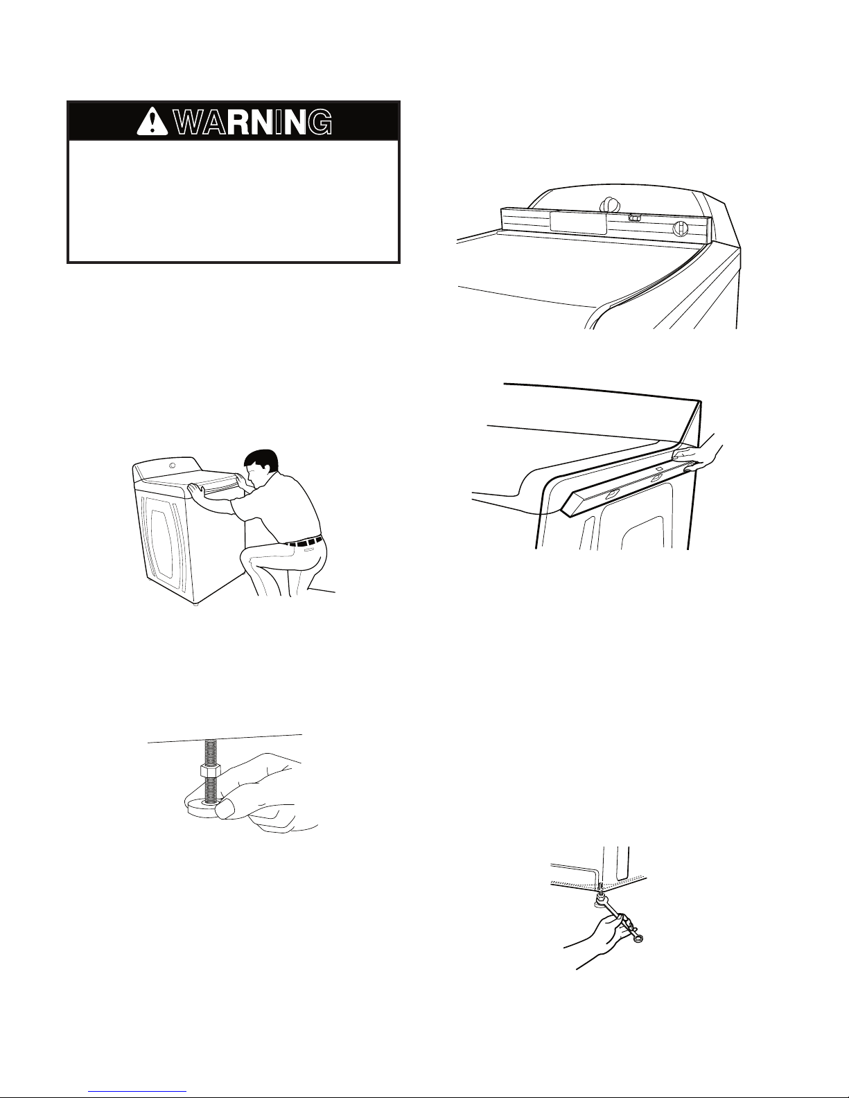
LEVEL THE WASHER
WARNING
Level the front.
Level the side
.
Excessive Weight Hazard
Use two or more people to move and
install washer.
Failure to do so can result in back or
other injury.
One washer foot has been installed at a different height on the washer. The other three
feet were preset at the factory. Properly level
ing your washer will minimize noise and vibra
tion.
1. Slide the washer to its final location.
2. Push on upper front panel to be sure the
washer is on its rear feet.
4. Check the levelness of the washer by
first placing a level on the lid near the
console. Next, place the level on the side
of the washer in the crease between the
top of the washer and the cabinet.
-
-
3. Lower right front foot until it contacts the
floor. By hand, firmly rotate foot as much
as an additional 1-1/2 turns. The other
three feet have been preset at the factory.
5. If the washer is not level, move the washer out slightly, tip back, prop up the front
of the washer on a wood block. Adjust the
feet up or down as necessary by twisting
the feet. Repeat steps 1 through 4 until
washer is level.
6. Use a 9/16˝ or 14 mm open-end wrench
to turn the locknut counterclockwise on
the foot tightly against the washer cabi
net.
IMPORTANT: If the locknut is not tight against
the washer cabinet, the washer may vibrate.
-
2-8

COMPLETE INSTALLATION
WARNING
1. Check the electrical requirements. Be
sure that you have the correct electrical
supply and the recommended grounding
method. See “Electrical Requirements,”
page 2-4.
2. Check that all parts are now installed. If
there is an extra part, go back through the
steps to see which step was skipped.
3. Check that you have all of your tools.
4. Keep the foam packing ring from the
washer tub for future relocation of the
washer. Dispose of or recycle all other
packaging materials.
5. Check that the water faucets are on.
Electrical Shock Hazard
Plug into a grounded 3 prong outlet.
Do not remove ground prong.
Do not use an adapter.
Do not use an extension cord.
Failure to follow these instructions can
result in death, fire, or electrical shock.
6. Check for leaks around faucets and inlet
hoses.
7. Plug into a grounded 3 prong outlet.
8. Remove any protective film or tape remaining on the washer.
9. Read “Washer Use,” page 3-3.
10. To test and to clean your washer, mea
sure 1/2 of the detergent manufacturer’s
recommended amount of High Efficiency
(HE) powdered or liquid detergent for a
medium size load and pour it into the de
tergent dispenser. Close the lid. Press
POWER. Select a normal cycle and press
Start. Allow it to complete one whole cycle.
-
-
2-9

— NOTES —
2-10
PRODUCT OPERATION
THEORY OF OPERATION
INTRODUCTION
The Cabrio™ Automatic Washer represents a
new design that differs from the traditional top
load machine. This washer operates without a
transmission, motor coupler, belt, basket drive
tube, or brake assembly.
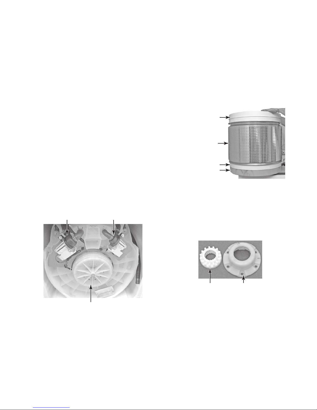
NEW COMPONENTS
The washer has the following new components:
Drive Motor—The drive motor is an electronically commutated direct drive 3-phase brush
less DC design that moves the impeller/agitator
and spin basket without the use of a transmis
sion. The motor is comprised of a stator that
is bolted to the base of the washer tub and a
rotor that is attached to the drive shaft. The
motor direction and speed is controlled by the
machine/motor controller, and is monitored by
a rotor position sensor, (RPS), located on the
stator.
Recirculation PumpDrain Pump
Basket—The basket is designed with a tra
ditional balance ring at the top and a flotation
chamber at the base. The outside surface of
the basket is punched to allow lint to catch on
the holes during the wash cycle. When the
water drains, the lint will be flushed off and
out the drain.
Balance Ring
-
-
Flotation Chamber
Basket Hub—The basket hub consists of two
splined components that engage or disengage
based on the position of the basket in the
vertical direction. The outer hub component
is fastened to the bottom of the basket, while
the inner component is attached to the end of
the drive shaft.
Basket
Balance Ring
-
Drive Motor
3-1
Inner Hub
(Drive Shaft)
Continued on the next page.
Outer Hub
(Basket)
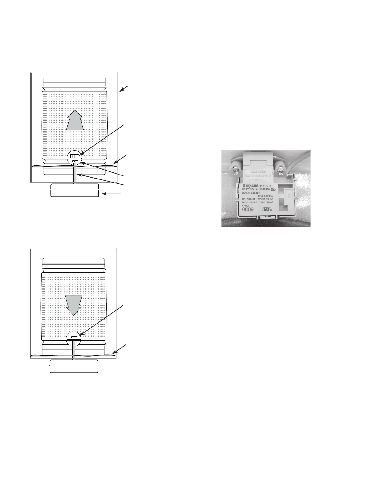
As the tub fills with water, the basket begins to
float and to rise. The splined hub components
now separate, and allow the basket to move
independently of the drive shaft.
Tub
Outer Basket Hub
Disengages
Water Level
Rises & Basket
Floats
Inner Hub Free
Drive Shaft
(Drive Motor)
When the tub drains, the basket drops back to
it’s original position, and the hub components
re-engage, connecting the basket to the shaft,
and permitting the basket to spin.
Lid Lock Mechanism—Since this washer
does not utilize a brake, a lid lock is used to
prevent access during the spin cycles. During
the drain and spin portions of the cycle, a lid
lock mechanism will lock the lid. The lid locks
are based on cycle phase. In general, the lid
locks when the basket spins greater than 23
rpm. After main wash, the lid is locked, and
remains locked until the end of the cycle. The
lid must be closed for the machine to fill, wash,
drain, or spin. Magnets in the washer lid close
a reed switch in the lid lock. This acts as the
lid switch.
Outer Basket Hub
Re-engages With Inner
Drive Shaft Hub
Water Level Drains
& Basket Drops
3-2
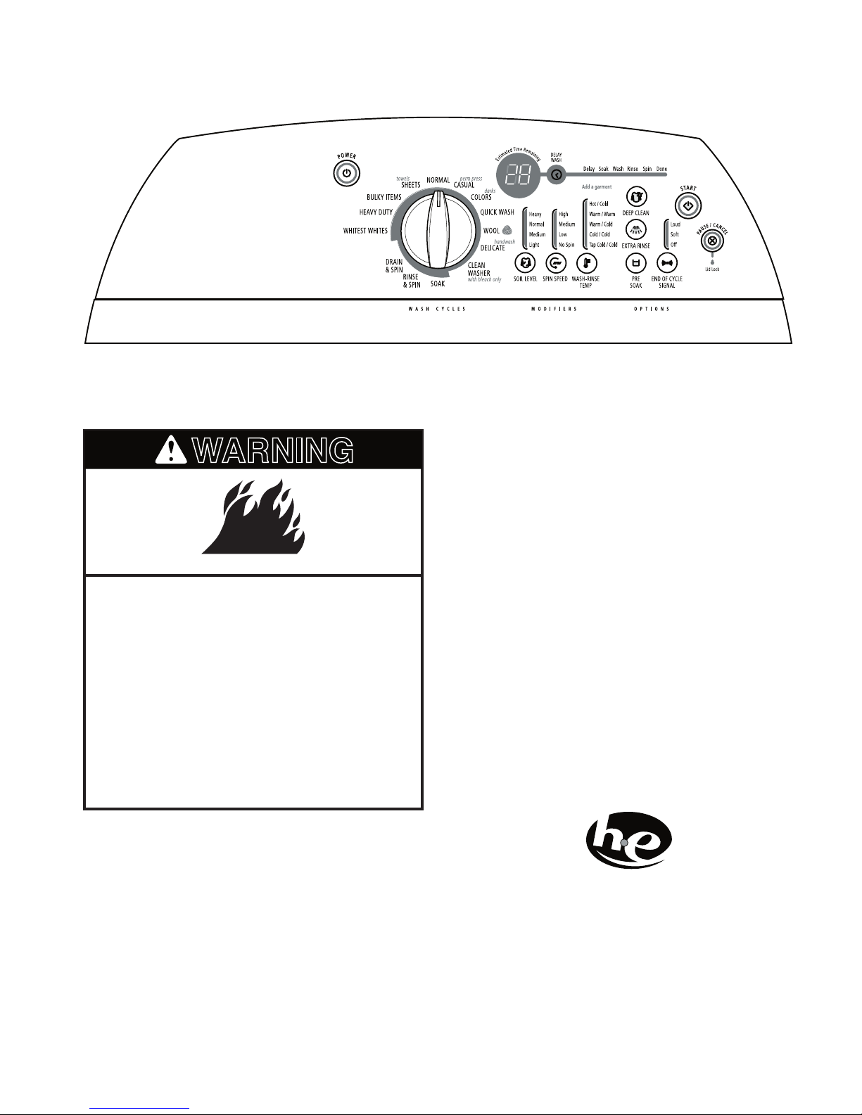
WASHER USE
WARNING
NOTE: Your washer model may differ slightly.
STARTING THE WASHER
Fire Hazard
Never place items in the washer that
are dampened with gasoline or other
flammable fluids.
No washer can completely remove oil.
Do not dry anything that has ever had
any type of oil on it (including cooking
oils).
Doing so can result in death, explosion,
or fire.
The following is a guide to starting the washer.
Periodic references to other sections of this
manual provide more detailed information.
USING THE PROPER DETERGENT
Use only High Efficiency (HE) detergents.
The package for this type of detergent will be
marked “HE” or “High Efficiency.” HE detergents
such as TIDE® HE are made to produce the
right amount of suds for the best performance
in low water wash systems. Follow the deter
gent manufacturer’s instructions to determine
the correct amount of detergent to use. The
washer’s new wash system will create too
much sudsing if regular non-HE detergent is
used. Using regular detergent will likely result in
washer errors, longer cycle times and reduced
rinsing performance.
It may also result in component failures and
noticeable mold or mildew.
-
3-3
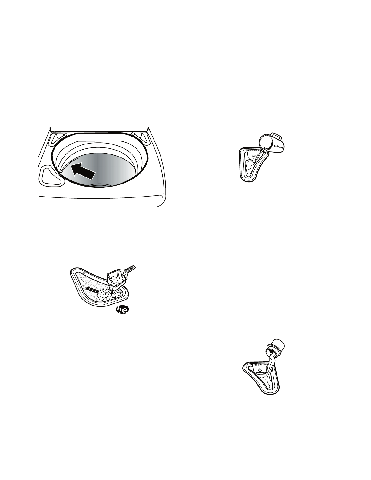
1. Place a load of sorted clothes into the
H
i
g
h
E
f
f
i
c
i
e
n
c
y
D
e
t
e
r
g
e
n
t
washer.
Load evenly to maintain washer bal
•
ance. Mix large and small items. Items
should move easily through the wash
water.
Load only to the top of the basket as
•
shown. Overloading can cause poor
cleaning. Items should move easily
through the wash water.
2. Pour measured powdered or liquid High
Efficiency (HE) detergent into the detergent
dispenser. Do not put detergent directly
into the wash tub or onto clothes in the
washer.
3. Add color-safe bleach, (powdered or liquid) to this dispenser, if needed. Be sure
-
to match powdered color-safe bleach with
powdered detergent or match liquid colorsafe bleach with liquid detergent.
4. Pour measured liquid chlorine bleach into
the liquid chlorine bleach dispenser, if
needed. Bleach is diluted and automati
cally dispensed at the proper time during
the wash cycle.
Do not overfill. Do not dilute. Do not use
•
more than 1 cup (250 mL) for a full load.
Use less with a smaller load size.
Follow the garment and the chlorine
•
bleach manufacturer’s directions for
proper use.
To avoid spilling, use a cup with a pour
•
ing spout. Do not let bleach splash, drip,
or run down into the washer basket.
At the end of the cycle, a small amount
•
of water may be left in the dispenser.
This is normal.
-
-
NOTE: Use only liquid chlorine bleach
in this dispenser.
5. Pour measured liquid fabric softener into
the fabric softener dispenser, if desired.
3-4
 Loading...