

Weslo 831.2976.3 Owner's Manual
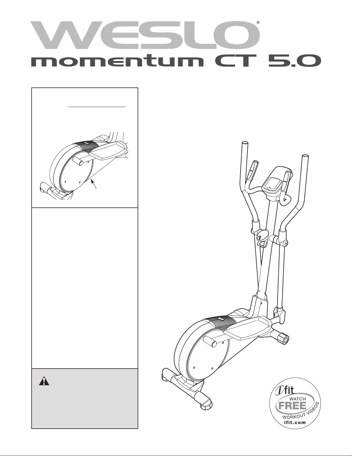
Model No. 831.29763.0
Serial No.
ELLIPTICAL EXERCISER
Write the serial number in the
space above for reference.
Serial Number
Decal
• Assembly
• Operation
• Maintenance
• Part List and Drawing
Userʼs Manual
Sears, Roebuck and Co.
Hoffman Estates, IL 60179
CAUTION
Read all precautions and instructions in this manual before using
this equipment. Keep this manual
for future reference.
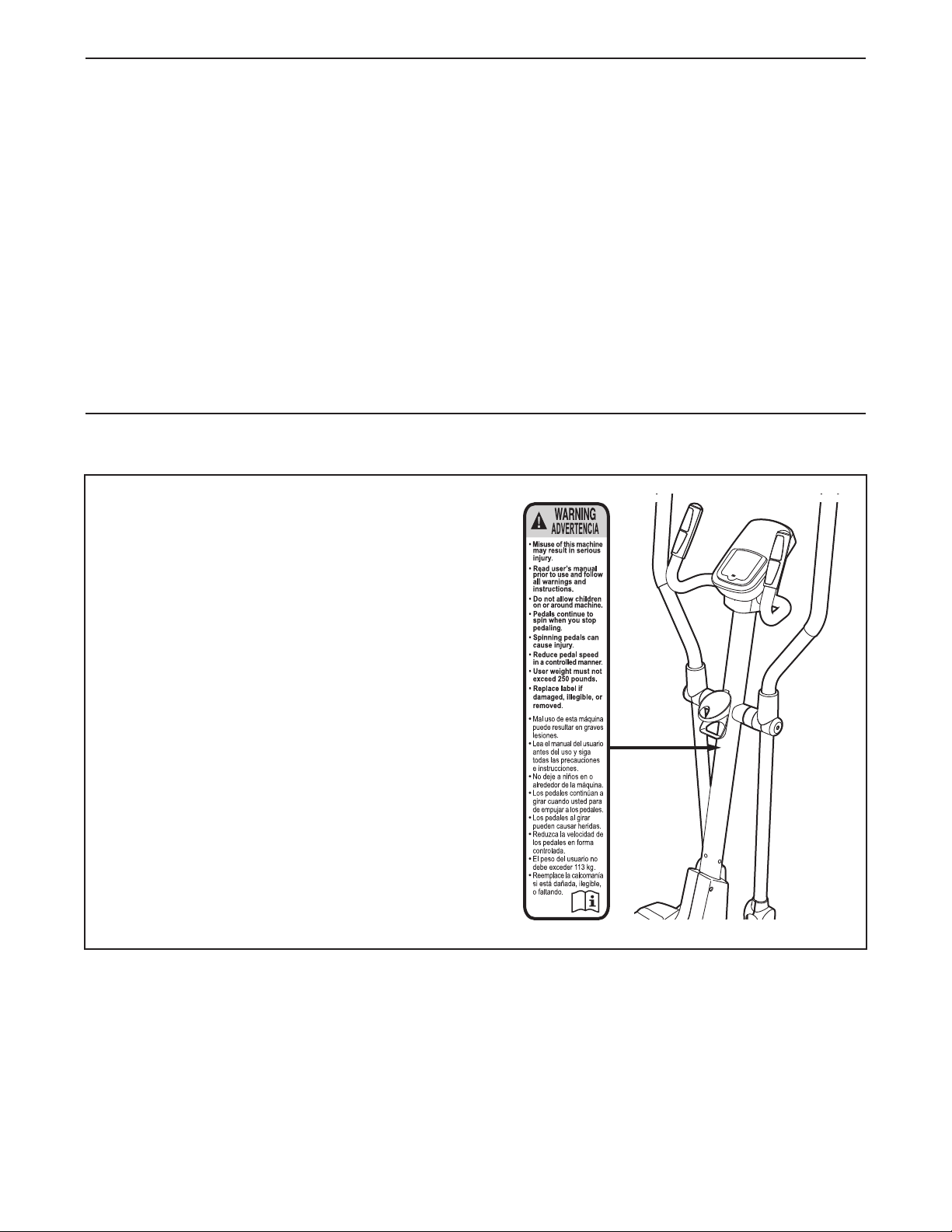
TABLE OF CONTENTS
WARNING DECAL PLACEMENT . . . . . . . . . . . . . . . . . . . . . . . . . . . . . . . . . . . . . . . . . . . . . . . . . . . . . . . . . . . . . .2
MPORTANT PRECAUTIONS . . . . . . . . . . . . . . . . . . . . . . . . . . . . . . . . . . . . . . . . . . . . . . . . . . . . . . . . . . . . . . . .3
I
BEFORE YOU BEGIN . . . . . . . . . . . . . . . . . . . . . . . . . . . . . . . . . . . . . . . . . . . . . . . . . . . . . . . . . . . . . . . . . . . . . .4
ASSEMBLY . . . . . . . . . . . . . . . . . . . . . . . . . . . . . . . . . . . . . . . . . . . . . . . . . . . . . . . . . . . . . . . . . . . . . . . . . . . . . . .5
HOW TO USE THE ELLIPTICAL . . . . . . . . . . . . . . . . . . . . . . . . . . . . . . . . . . . . . . . . . . . . . . . . . . . . . . . . . . . . .15
MAINTENANCE AND TROUBLESHOOTING . . . . . . . . . . . . . . . . . . . . . . . . . . . . . . . . . . . . . . . . . . . . . . . . . . .19
EXERCISE GUIDELINES . . . . . . . . . . . . . . . . . . . . . . . . . . . . . . . . . . . . . . . . . . . . . . . . . . . . . . . . . . . . . . . . . . .21
PART LIST . . . . . . . . . . . . . . . . . . . . . . . . . . . . . . . . . . . . . . . . . . . . . . . . . . . . . . . . . . . . . . . . . . . . . . . . . . . . . .22
EXPLODED DRAWING . . . . . . . . . . . . . . . . . . . . . . . . . . . . . . . . . . . . . . . . . . . . . . . . . . . . . . . . . . . . . . . . . . . .23
ORDERING REPLACEMENT PARTS . . . . . . . . . . . . . . . . . . . . . . . . . . . . . . . . . . . . . . . . . . . . . . . . . .Back Cover
90 DAY FULL WARRANTY . . . . . . . . . . . . . . . . . . . . . . . . . . . . . . . . . . . . . . . . . . . . . . . . . . . . . . . . . .Back Cover
WARNING DECAL PLACEMENT
This drawing shows the location(s) of the warning
decal(s). If a decal is missing or illegible, call
1-866-699-3756 and request a free replacement decal. Apply the decal in the location
shown. Note: The decal(s) may not be shown at
actual size.
2

IMPORTANT PRECAUTIONS
WARNING: To reduce the risk of serious injury, read all important precautions and
instructions in this manual and all warnings on your elliptical before using your elliptical. Sears
assumes no responsibility for personal injury or property damage sustained by or through the use of
his product.
t
1. Before beginning any exercise program,
consult your physician. This is especially
important for persons over age 35 or
persons with pre-existing health problems.
2. Use the elliptical only as described in this
manual.
3. It is the responsibility of the owner to ensure
that all users of the elliptical are adequately
informed of all precautions.
4. The elliptical is intended for home use only.
Do not use the elliptical in a commercial,
rental, or institutional setting.
5. Keep the elliptical indoors, away from
moisture and dust. Do not put the elliptical in
a garage or covered patio, or near water.
6. Place the elliptical on a level surface, with at
least 3 ft. (0.9 m) of clearance in the front
and rear of the elliptical and 2 ft. (0.6 m) on
each side. To protect the floor or carpet from
damage, place a mat under the elliptical.
9. The elliptical should not be used by persons
weighing more than 250 lbs. (113 kg).
10. Wear appropriate clothes while exercising;
do not wear loose clothes that could become
caught on the elliptical. Always wear athletic
shoes for foot protection while exercising.
11. Hold the handlebars or the upper body arms
when mounting, dismounting, or using the
elliptical.
12. The pulse sensor is not a medical device.
Various factors may affect the accuracy of
heart rate readings. The pulse sensor is
intended only as an exercise aid in
determining heart rate trends in general.
13. The elliptical does not have a freewheel; the
pedals will continue to move until the
flywheel stops. Reduce your pedaling speed
in a controlled way.
14. Keep your back straight while using the
elliptical; do not arch your back.
7. Inspect and properly tighten all parts
regularly. Replace any worn parts
immediately.
8. Keep children under age 12 and pets away
from the elliptical at all times.
15. Over exercising may result in serious injury
or death. If you feel faint or if you experience
pain while exercising, stop immediately and
cool down.
3
BEFORE YOU BEGIN
Thank you for selecting the new WESLO
OMENTUM CT 5.0 elliptical. The MOMENTUM CT
M
5.0 provides a selection of features designed to make
your workouts at home more effective and enjoyable.
For your benefit, read this manual carefully before
you use the elliptical. If you have questions after
reading this manual, please see the back cover of this
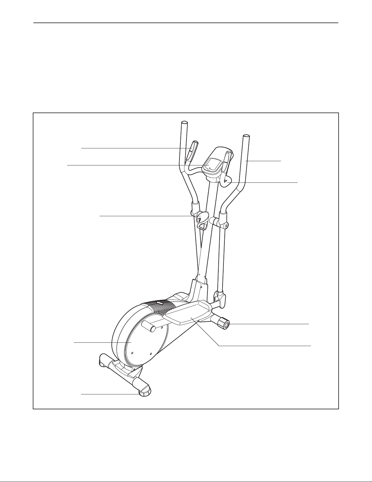
Pulse Sensor
Console
Water Bottle Holder*
®
manual. To help us assist you, note the product model
umber and serial number before contacting us. The
n
model number and the location of the serial number
decal are shown on the front cover of this manual.
Before reading further, please familiarize yourself with
the parts that are labeled in the drawing below.
Upper Body Arm
Handlebar
Pedal Disc
Leveling Foot
Wheel
Pedal
*Water bottle is not included
4
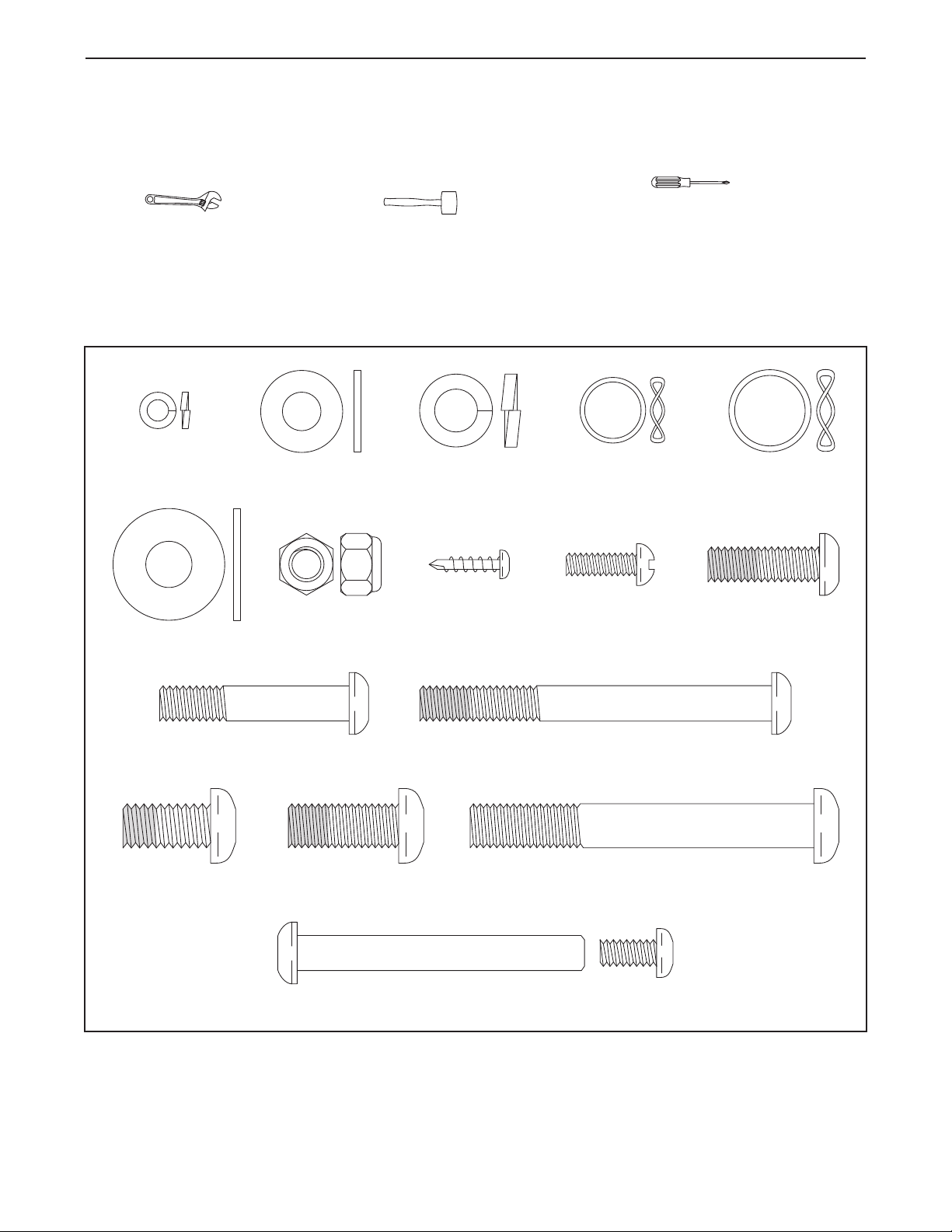
M10 Split
Washer (45)–4
M
M10
Washer (83)–2
M8 Locknut
(38)–8
Small Wave
Washer (69)–2
M5 Split
Washer (28)–6
M8 x 25mm Patch
Screw (56)–2
M8 Washer
(55)–2
M6 Bolt Set (25)–2
Large Wave
Washer (76)–2
M4 x 16mm
Self-tapping
Screw (52)–12
M10 x 78mm Button
Bolt (34)–4
M10 x 20mm Patch
Screw (7)–4
M10 x 25mm
Patch Screw (40)–2
M8 x 80mm Patch
Bolt (79)–2
M8 x 43mm Button
Bolt (50)–6
#10 x 16mm
Screw (27)–6
ASSEMBLY
Assembly requires two persons. Place all parts of the elliptical in a cleared area and remove all packing mate-
rials; do not dispose of the packing materials until assembly is completed.
In addition to the included tool(s), assembly requires a Phillips screwdriver , an adjustable
rench , and a rubber mallet .
w
See the drawings below to identify the small parts needed for assembly. The number in parentheses below each
drawing is the key number of the part, from the PART LIST near the end of this manual. The number following
the key number is the quantity needed for assembly. Note: If a part is not in the hardware kit, check to see if
it has been preassembled. If a part is missing, please call 1-866-699-3756. To avoid damaging parts, do
not use power tools for assembly.
5
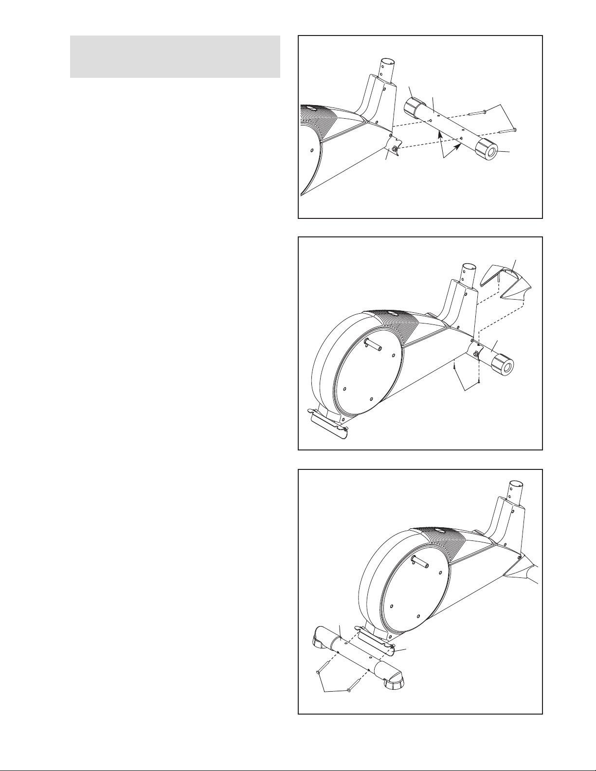
1.
To make assembly easier, read the
information on page 5 before you begin.
Identify the Front Stabilizer (63), which has a
Wheel (21) on each end.
Orient the Front Stabilizer (63) so that the small
holes face downward.
While a second person lifts the front of the
Frame (1), attach the Front Stabilizer (63) to the
Frame with two M10 x 78mm Button Bolts (34).
1
21
63
1
Small
Holes
4
3
21
2. Insert the Front Stabilizer Cover (68) into the
Front Stabilizer (63).
Attach the Front Stabilizer Cover (68) with two
M4 x 16mm Self-tapping Screws (52).
3. While a second person lifts the rear of the
Frame (1), attach the Rear Stabilizer (9) to the
Frame with two M10 x 78mm Button Bolts (34).
2
68
63
52
3
9
1
34
6
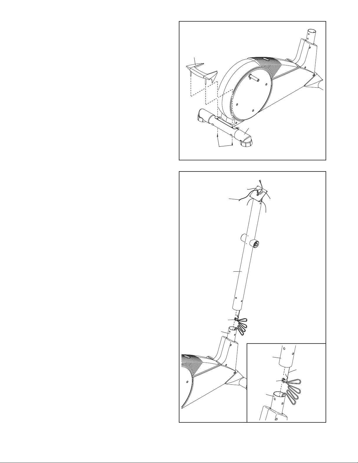
4. Insert the Rear Stabilizer Cover (67) into the
Rear Stabilizer (9).
Attach the Rear Stabilizer Cover (67) with two
M4 x 16mm Self-tapping Screws (52).
4
67
9
52
5. Orient the Upright (2) as shown. Have a second
person hold the Upright near the Frame (1).
See the inset drawing. Locate the wire tie in
the Upright (2). Tie the lower end of the wire tie
to the Wire Harness (73). Then, pull the upper
end of the wire tie until the Wire Harness is
routed through the Upright.
Tip: To prevent the Wire Harness (73) from
falling into the Upright (2), secure the Wire
Harness with the wire tie.
Tip: Avoid pinching the Wire Harness (73).
Slide the Upright (2) onto the Frame (1).
5
Wire Tie
2
73
1
Avoid pinching the
Wire Harness (73)
2
Wire Tie
73
1
7
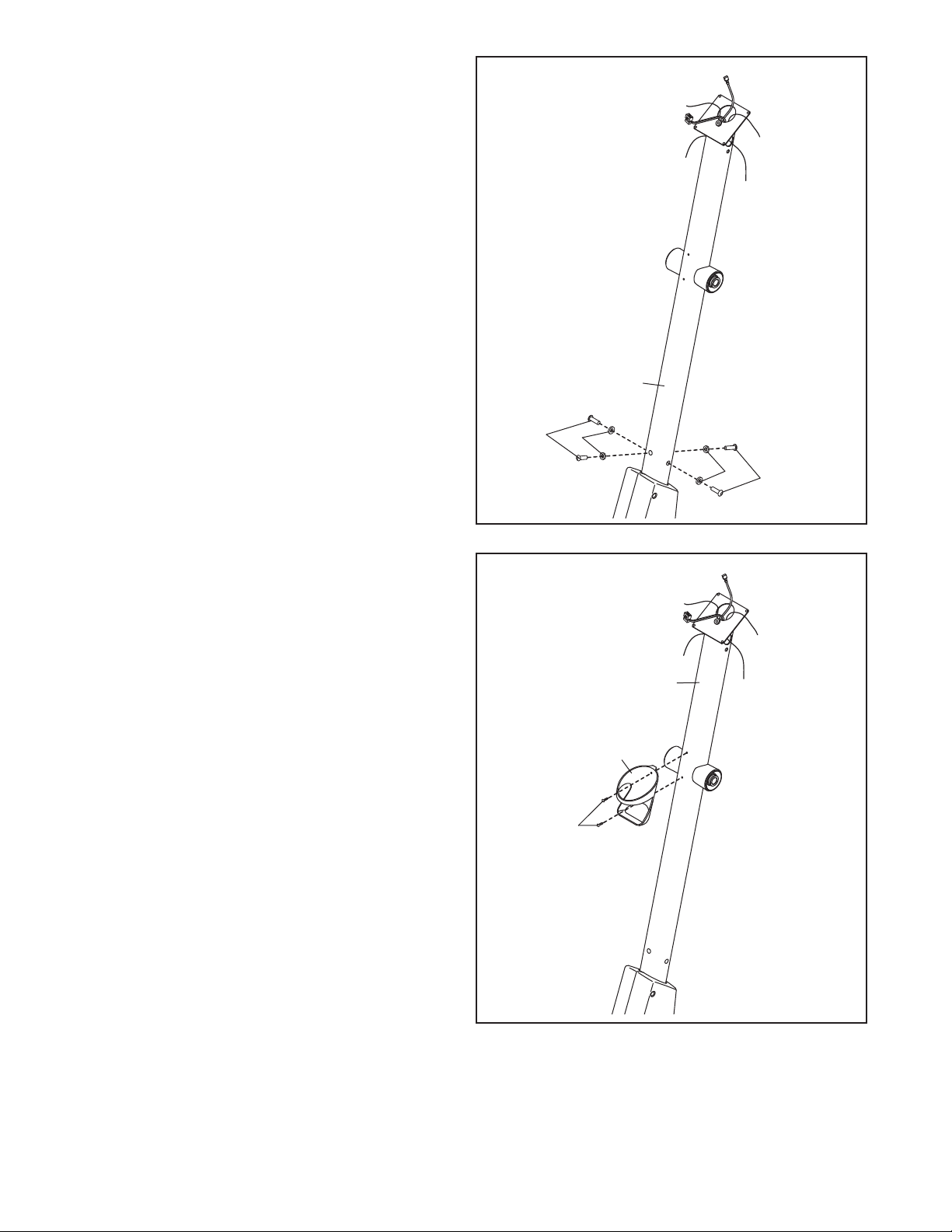
6. Attach the Upright (2) to the Frame (not shown)
with four M10 x 20mm Patch Screws (7) and
four M10 Split Washers (45). Do not tighten
the Patch Screws yet.
6
2
7
45
45
7
7. Attach the Water Bottle Holder (29) to the
Upright (2) with two M4 x 16mm Self-tapping
Screws (52).
7
2
29
52
8
 Loading...