

Weslo 831295021 Owner’s Manual
ModetNo.831.295021
SeriaJNo.
WritetheseriaUnumberinthe
spaceaboveforfuturereference,
SeriaUNumber
DecaU
Assembly
Operation
Maintenance
Part List and Drawing
, ,CAUTION
Read aHprecautions and instrueo
tions in this manual before using
this equipment. Save this rnanuaJ
for future reference.
Sears, Roebuck and Co., Roffman Estates, IL 60179
TABLE OF CONTENTS
iMPORTANT PRECAUTIONS ................................................................ 2
BEFORE YOU BEGIN ...................................................................... 4
ASSEMBLY .............................................................................. 5
OPERATION AND ADJUSTMENT ............................................................. 8
HOW TO FOLD AND MOVE THE TREADMILL ................................................. 11
MAINTENANCE AND TROUBLESHOOTING ................................................... 12
CONDiTiONiNG GUiDELiNES .............................................................. 14
ORDERING REPLACEMENT PARTS ................................................. Back Cover
FULL 90 DAY WARRANTY .......................................................... Back Cover
Note: An EXPLODED DRAWING and a PART LiST are attached in the center of this manual.
IMPORTANT PRECAUTIONS
WARNING: To educethedskofburne,f re,electricehook,or oju, topersons,read
the following important precautions and information before operating the tread mill.
1. it is the responsibility of the owner to ensure 10. When connecting the power cord (see page 8),
that all users of this treadmill are adequateJy pJug the power cord into a surge suppressor
informed of aH warnings and precautions. (not incJuded) and pJug the surge suppressor
2. Use the treadmill onJy as described.
3. Place the treadmill on a leveJ surface, with at
least eight feet of clearance behind it and two
feet on each side. Do not place the treadmill
on any surface that blocks air openings. To
protect the Hoot or carpet from damage,
place a mat under the treadmill
4. Keep the treadmill indoors, away from mois-
ture and dust. Do not put the treadmill in a
garage or covered patio, or near water.
5. Do not operate the treadmill where aerosol
products are used or where oxygen is being
administered.
6. Keep children under the age of !2 and pets
away from the treadmiff at aH times.
7. The treadmill should not be used by persons
weighing more than 250 pounds.
8. Never affow more than one person on the
treadmill at a time.
9. Wear suitabJe exercise cJothee when using
the treadmill. Do not wear loose clothes that
could become caught in the treadmill.
AtHetic support clothes are recommended
for both men and women. Always wearathlet-
ic shoes. Never use the treadmill with bare
feet, wearing only stockings, or in sandals.
into a grounded circuit ca pabJe of carrying 15
or more amps. No other appliance shoutd be
on the same circuit. Do not use an extension
cord.
11. Use only a eingJe-outJet eurge suppressor that
meets aH of the specifications described on
page 8. To purchase a surge suppressor, see
your locaJ Sears store or call 1o800-366-7278
and order part number 146148, or see your
Jocal eJectronics store.
12. Failure to use a properly functioning surge
suppressor could reeuff in damage to the con-
troJ system of the treadmiff, ff the control sys-
tem is damaged, the walking belt may change
speed, accelerate, or stop unexpectedJy,
which may result in a fail and serious injury.
13. Keep the power cord and the surge suppres-
sor away from heated surfaces.
14. Never move the walking belt while the power
is turned off. Do not operate the treadmill if
the power cord or pJug is damaged, or if the
treadmill ie not working properly. (See page 4
if the treadmill is not working properJy.}
15. Never start the treadmill while you are stand-
ing on the walking belt. AJwaye hold the
16.The treadmHJ is capable of high speeds. 21. inspect and properly tighten all parts of the
Adjust the speed in small increments to treadmill regularly.
avoid sudden jumps in speed.
17. Never leave the treadmill unattended while it is opening.
running. Always remove the key and unplug _Lmn'_
the power cord when the treadmill is not in 23. uP_l_,_E}_: Always unplug the power
use. cord immediately after use, before cleaning
18. Do not attempt to raise, Iower_ or move the
treadmill until it is property assembled. ISee
ASSEMBLY on page 5, and HOW TO MOVE
THE TREADMmLL on page 11.) You must be
able to safely Hft 45 pounds (20 kg) to raise,
Jower, or move the treadmill.
19. Do not change the incline of the treadmill by
placing objects under the treadmill 24. This treadmill is intended for in=home use
20. When folding or moving the treadmill, make onJy. Do not use this treadmill in any corn-
sure that the storage latch is fully closed, mercial, rentaJ, or institutional setting.
22. Never drop or insert any object into any
the treadmill, and before performing the
maintenance and adjustment procedures
described in this manual Never remove the
motor hood unless instructed to do so by an
authorized service representative. Servicing
other than the procedures in this manual
should be performed by an authorizedser-
vicerepresentative only.
WARNING: Beforebeginningthisorany0xerc eeprogram,consultyourphysician.
This is especially important for persons over the age of 35 or persons with pre-existing health prob-
lems. Read aH instructions before using. Sears assumes no responsibility for personal injury or
property damage sustained by or through the use of this product.
SAVE THESE iNSTRUCTiONS
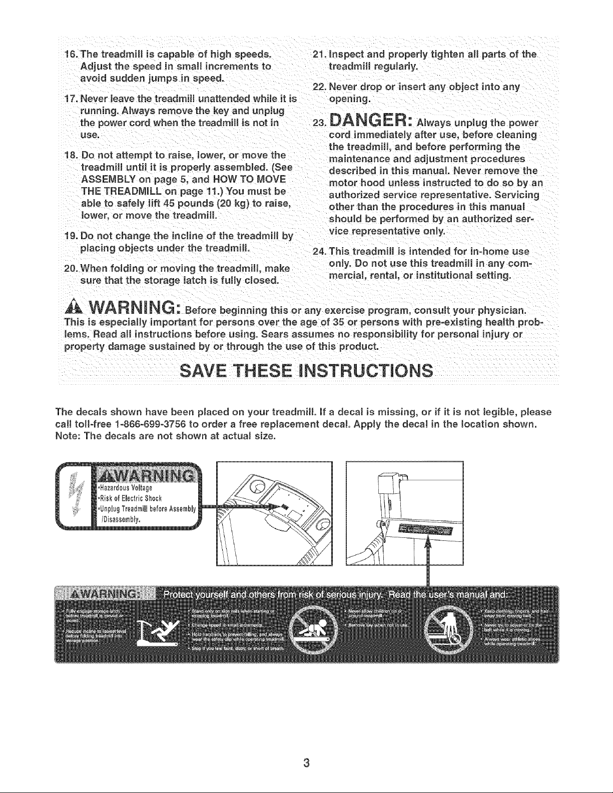
The decaJs shown have been placed on your treadmill, if a decaJ is missing, or if it is not Jegible, please
call toll-free 1=806-69g-3756 to order a free replacement decal Apply the decaJ in the tocation shown.
Note: The decals are not shown at actual size.
3
BEFORE YOU BFGmN
Thank you for selecting the WESLO _ CADENCE 78S
treadmill, The CADENCE 78S treadmill combines
advanced technology with innovative design to let you
enjoy an excellent form of cardiovascular exercise in
the convenience and privacy of your home, And when
you're not exercising, the unique CADENCE 78S
treadmill can be folded up, requiring less than half the
floor space of other treadmills,
For your benefit, read this manuaJ carefully before
using the treadmill, if you have questions after read-
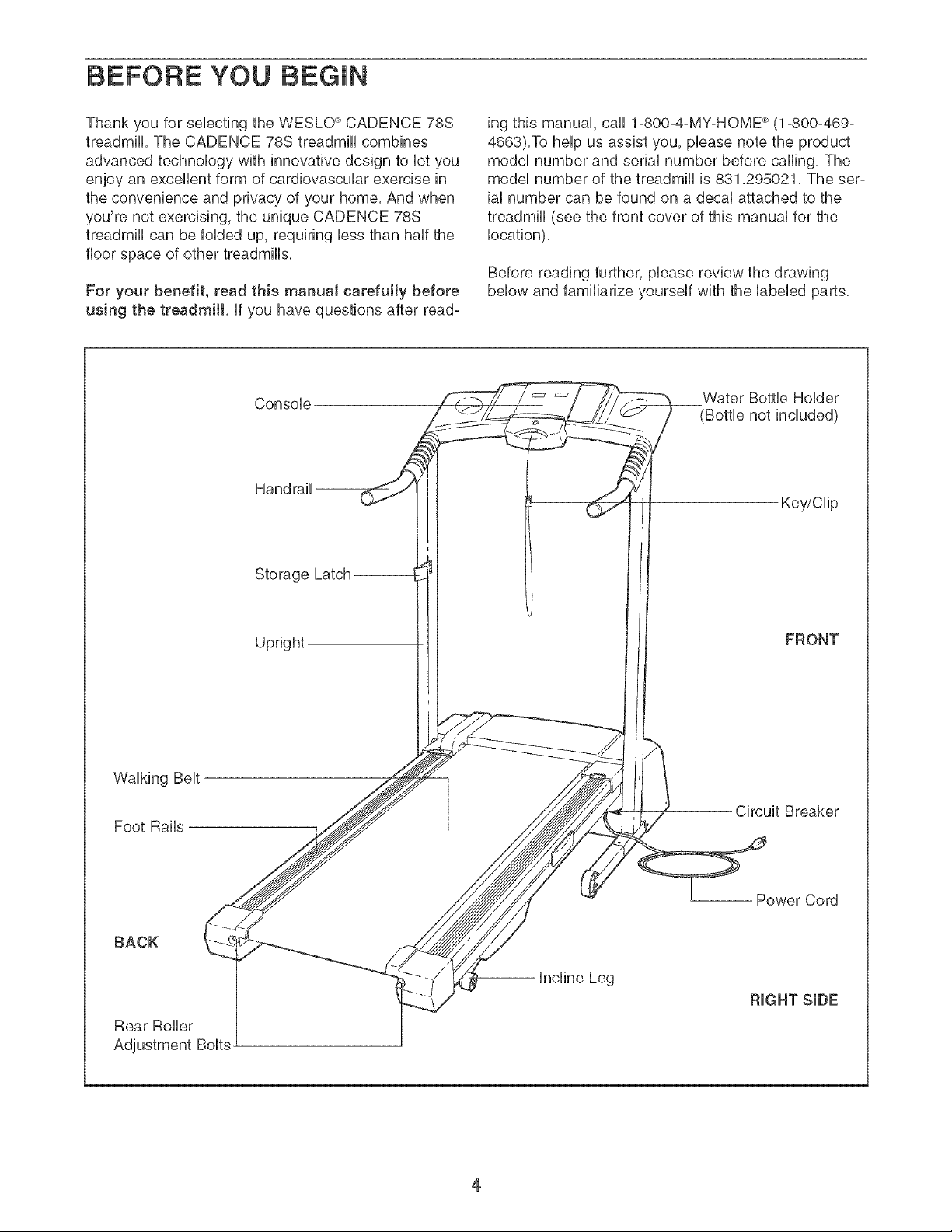
Console
Handrail --
Storage Latch
ing this manual, call 1-800-4-MY-HOME _ (1-800-469-
4663),To help us assist you, please note the product
model number and serial number before calling, The
model number of the treadmill is 831,295021, The ser-
ial number can be found on a decal attached to the
treadmill (see the front cover of this manual for the
location),
Before reading further, please review the drawing
below and familiarize yourself with the labeled parts,
Water Bottle Holder
(Bottle not included)
Key/Clip
Walking Belt
Foot Rails
BACK
Rear Roller
Adjustment Bolts
Upright
FRONT
Circuit Breaker
Power Cord
Incline Leg
RIGHT SIDE
4
Assembly requires two persons. Set the treadmHUin a cleared area and remove aHpacking materiaUs, Do not
dispose of the packing materiaUs until assembUy is compUeted,
Note: The underside of the treadmill walking belt is coated with high-performance lubricant, During shipping, a
small amount of lubricant may be transferred to the top of the walking belt or the shipping carton, This is a nor-
mal condition and does not affect treadmill pedormance, if there is lubricant on top of the walking belt, simply
wipe off the lubricant with a soft cloth and a mild, non-abrasive cleaner,
Assembly requires the included allen wrenches _ and your own phillips screwdriver
E
wire cutters ___._4o_, and needtenose pliers
To identify small parts, use the PART IDENTIFICATION CHART attached in the center of this manual
Note: if a part is not in the parts bag, first check to see if it has been prs-assembUsd, If a part is missing,
call toll-free 1-888-899-3758.
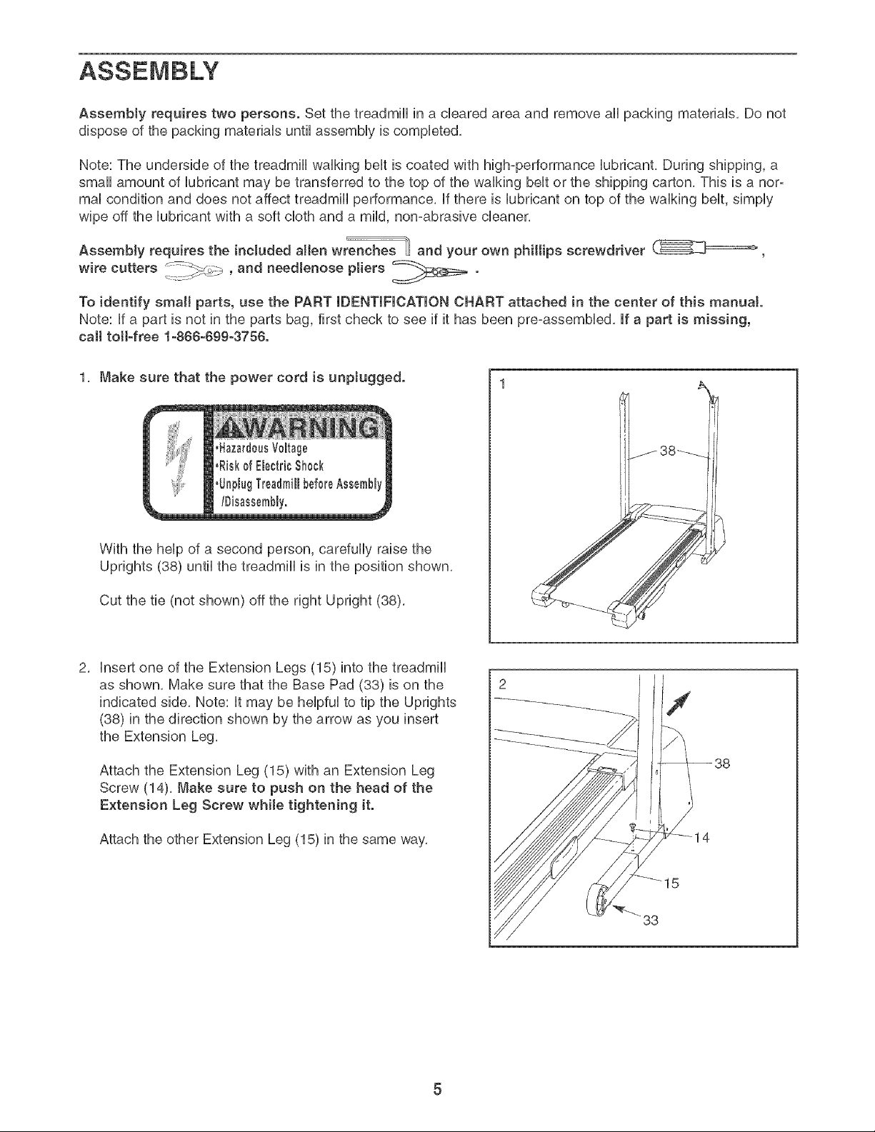
1, Make sure that the power cord is unpJugged.
With the help of a second person, carefully raise the
Uprights (88) until the treadmill is in the position shown,
Cut the tie (not shown) off the right Upright (38),
insert one of the Extension Legs (15) into the treadmill
as shown, Make sure that the Base Pad (33) is on the
indicated side, Note: it may be helpful to tip the Uprights
(38) in the direction shown by the arrow as you insert
the Extension Leg,
Attach the Extension Leg (15) with an Extension Leg
Screw (14), Make sure to push on the head of the
Extension Leg Screw while tightening it.
Attach the other Extension Leg (15) in the same way,
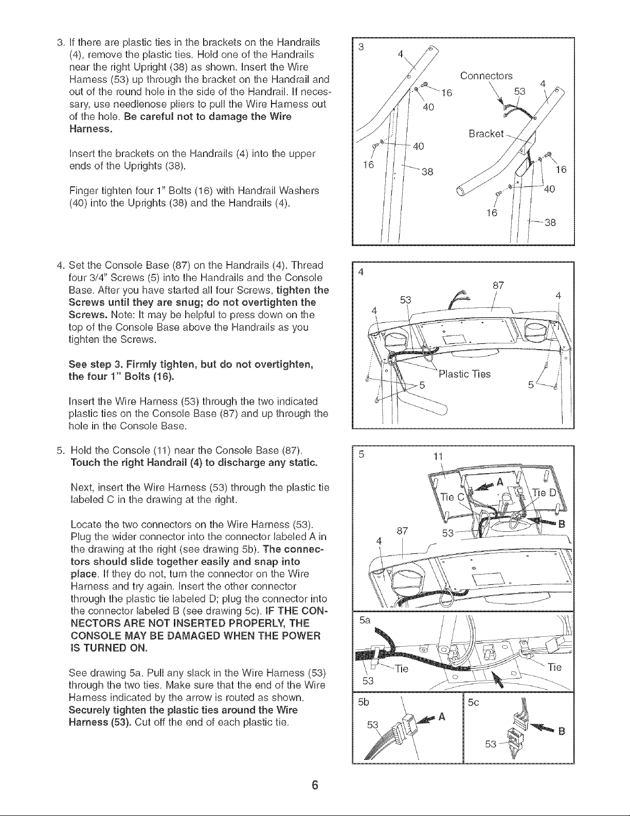
3,fftherearepUastictiesinthebracketsontheHandrails
(4),removetheplasticties,HoUdoneoftheHandrails
neartherightUpright(38)asshown,[nserttheWire
Harness(53)upthroughthebracketontheHandrailand
outoftheroundhoUeinthesideoftheHandrail,ffneces-
sary,useneedUenoseplierstopulltheWireHarnessout
ofthehoUe,Becarefu[notto damagethe Wire
Harness.
[nsertthebracketsontheHandrails(4)intotheupper
endsoftheUprights(38),
Fingertightenfour1"BoUts(16)withHandrailWashers
(40)intotheUprights(38)andtheHandrails(4),
4, Set the ConsoUe Base (87) on the Handrails (4), Thread
four 3/4" Screws (5) into the Handrails and the ConsoUe
Base, After you have started aHfour Screws, tighten the
Screws until they are snug; do not overtighten the
Screws. Note: It may be helpful to press down on the
top of the Console Base above the Handrails as you
tighten the Screws,
4\
\
Connectors
\ 53
Bracket
16
87
53
4
See step 3. Firmly tighten, but do not overtighten,
the four 1" Bolts (16).
hsert the Wire Harness (53) through the two indicated
plastic ties on the Console Base (87) and up through the
hole in the Console Base.
5. Hold the Console (11) near the Console Base (87).
Touch the right Handrait (4) to discharge any static.
Next, insert the Wire Harness (53) through the plastic fie
labeled C in the drawing at the right,
Locate the two connectors on the Wire Harness (53),
Plug the wider connector into the connector labeled A in
the drawing at the right (see drawing 5b), The connec-
tors should slide together easily and snap into
place, If they do not, turn the connector on the Wire
Harness and try again, Insert the other connector
through the plastic tie labeled D; plug the connector into
the connector labeled B (see drawing 5c), IF THE CON-
NECTORS ARE NOT INSERTED PROPERLY, THE
CONSOLE MAY BE DAMAGED WHEN THE POWER
IS TURNED ON.
T[es
5 11
87
See drawing 5a, Pull any slack in the Wire Harness (53)
through the two ties, Make sure that the end of the Wire
Harness indicated by the arrow is routed as shown,
Securely tighten the plastic ties around the Wire
Harness (53). Cut off the end of each plastic tie,
6
53
5c
B
 Loading...