

Page 1
R
SCANTEAM 3700 CCD
Page 2

Disclaimer
Welch Allyn, Data Collection, Inc. (d/b/a Hand Held Products) reserves the right to make changes in
specifications and other information contained in this document without prior notice, and the reader should in all
cases consult Hand Held Products to determine whether any such changes have been made. The information in
this publication does not represent a commitment on the part of Hand Held Products.
Hand Held Products shall not be liable for technical or editorial errors or omissions contained herein; nor for
incidental or consequential damages resulting from the furnishing, performance, or use of this material.
This document contains proprietary information which is protected by copyright. All rights are reserved. No
part of this document may be photocopied, reproduced, or translated into another language without the prior
written consent of Hand Held Products.
E2000 Welch Allyn Data Collection, Inc. All rights reserved.
Web Address: www.handheld.com
This device complies with part 15 of the FCC Rules. Operation is subject to the following two
conditions: (1) this device may not cause harmful interference, and (2) this device must accept
any interference received, including interference that may cause undesired operation.
FCC Class B Compliance Statement
This equipment has been tested and found to comply with the limits for a Class B digital device
pursuant to part 15 of the FCC Rules. These limits are designed to provide reasonable
protection against harmful interference in a residential installation. This equipment
generates, uses, and can radiate radio frequency energy and, if not installed and used in
accordance with the instructions, may cause harmful interference to radio communications.
However, there is no guarantee that interference will not occur in a particular installation. If
this equipment does cause harmful interference to radio or television reception, which can be
determined by turning the equipment off and on, the user is encouraged to try to correct the
interference by one or more of the following measures:
• Reorient or relocate the receiving antenna.
• Increase the separation between the equipment and receiver.
• Connect the equipment into an outlet on a circuit different from that to which the receiver
is connected.
• Consult the dealer or an experienced radio or television technician for help.
Caution: Any changes or modifications made to this device that are not expressly
approved by Welch Allyn, Inc. may void the user’s authority to operate the equipment.
Note: To maintain compliance with FCC Rules and Regulations, cables connected to this device must
be shielded cables, in which the cable shield wire(s) have been grounded (tied) to the connector shell.
Canadian Notice
This equipment does not exceed the Class B limits for radio noise emissions as described in
the Radio Interference Regulations of the Canadian Department of Communications.
Le present appareil numerique n’emet pas de bruits radioelectriques depassant les limites
applicables aux appareils numeriques de la classe B prescrites dans le Reglement sur le
brouillage radioelectrique edicte par le ministere des Communications du Canada.
The word SCANTEAM, the SCANTEAM logo, and the Welch Allyn logo are trademarks of Welch Allyn, Inc.
Throughout this manual, trademarked names may be used. Rather than put a trademark (TM) symbol in every
occurrence of a trademarked name, we state that we are using the names only in an editorial fashion, and to the
benefit of the trademark owner, with no intention of infringement.
Page 3

The CE mark on the product indicates that the system has been tested to and
conforms with the provisions noted within the 89/336/EEC Electromagnetic
Compatibility Directive and the 73/23/EEC Low Voltage Directive.
For further information, please contact:
Welch Allyn Ltd.
1st Floor
Dallam Court Dallam Lane
Warrington, Cheshire WA2 7LT
England
Welch Allyn shall not be liable for use of our product with equipment
(i.e., power supplies, personal computers, etc.) that is not CE marked and
does not comply with the Low Voltage Directive.
Patents
The SCANTEAM 3700 product is covered by the following U.S. Patent: 5,932,862. Other U.S. and foreign patents pending.
Page 4

Page 5

TABLE OF CONTENTS
Disclaimer
Agency Compliance
Chapter 1 SCANTEAM 3700 Description
Section Page
1.1 Introduction 1–1. . . . . . . . . . . . . . . . . . . . . . . . . . . . . . . . . . . . . . . . . .
1.2 SCANTEAM 3700 Hardware Description 1–1. . . . . . . . . . . . . . . .
1.2.1 Interface Port 1–2. . . . . . . . . . . . . . . . . . . . . . . . . . . . .
1.2.2 Nonvolatile Memory 1–2. . . . . . . . . . . . . . . . . . . . . . . .
1.3 SCANTEAM 3700 Software Description 1–2. . . . . . . . . . . . . . . . .
Chapter 2 System Hardware Description
Section Page
2.1 Introduction 2–1. . . . . . . . . . . . . . . . . . . . . . . . . . . . . . . . . . . . . . . . . .
2.2 General Characteristics of the 3700 2–2. . . . . . . . . . . . . . . . . . . . .
2.2.1 Mechanical Layout of the 3700 2–2. . . . . . . . . . . . . .
2.2.2 Single Modular Connector Port 2–3. . . . . . . . . . . . . .
2.2.3 Audible Indicator 2–3. . . . . . . . . . . . . . . . . . . . . . . . . . .
2.2.4 Mounting Inserts 2–3. . . . . . . . . . . . . . . . . . . . . . . . . . .
2.3 Operating Theory 2–3. . . . . . . . . . . . . . . . . . . . . . . . . . . . . . . . . . . . .
2.4 Scanner/Host Communication 2–4. . . . . . . . . . . . . . . . . . . . . . . . . .
2.4.1 Communications Port 2–4. . . . . . . . . . . . . . . . . . . . . .
2.4.2 Asynchronous ASCII Interface 2–4. . . . . . . . . . . . . . .
2.4.3 Hardwire Pinouts 2–5. . . . . . . . . . . . . . . . . . . . . . . . . .
2.5 Power Requirements 2–6. . . . . . . . . . . . . . . . . . . . . . . . . . . . . . . . . .
Chapter 3 Set–Up and Installation
Section Page
3.1 Introduction 3–1. . . . . . . . . . . . . . . . . . . . . . . . . . . . . . . . . . . . . . . . . .
3.2 General Preparation for Use 3–1. . . . . . . . . . . . . . . . . . . . . . . . . . .
3.3 Set–Up Procedure for Evaluation of the 3700 3–2. . . . . . . . . . . .
3.3.1 Preparation 3–2. . . . . . . . . . . . . . . . . . . . . . . . . . . . . . .
3.3.2 Set–up Procedure 3–3. . . . . . . . . . . . . . . . . . . . . . . . .
3.4 Installation in the Host Instrument 3–4. . . . . . . . . . . . . . . . . . . . . . .
i
Page 6

Chapter 4 Configuring the SCANTEAM 3700
Section Page
4.1 Preparation 4–1. . . . . . . . . . . . . . . . . . . . . . . . . . . . . . . . . . . . . . . . . .
4.2 Command Conventions 4–2. . . . . . . . . . . . . . . . . . . . . . . . . . . . . . .
4.3 Operational Commands 4–3. . . . . . . . . . . . . . . . . . . . . . . . . . . . . . .
4.4 Configuration Commands 4–5. . . . . . . . . . . . . . . . . . . . . . . . . . . . . .
4.5 Configuration Status Query Commands 4–15. . . . . . . . . . . . . . . . .
4.6 Default Operating Parameters 4–16. . . . . . . . . . . . . . . . . . . . . . . . . .
Chapter 5 Service/Technical Assistance
Section Page
5.1 Maintenance 5–1. . . . . . . . . . . . . . . . . . . . . . . . . . . . . . . . . . . . . . . . .
5.2 Troubleshooting Guide 5–1. . . . . . . . . . . . . . . . . . . . . . . . . . . . . . . .
5.2.1 Troubleshooting Hints 5–1. . . . . . . . . . . . . . . . . . . . . .
5.2.2 Diagnostic Procedure 5–2. . . . . . . . . . . . . . . . . . . . . .
5.2.3 Troubleshooting Checklist 5–2. . . . . . . . . . . . . . . . . .
5.3 Obtaining Factory Service 5–3. . . . . . . . . . . . . . . . . . . . . . . . . . . . .
5.3.1 Service Under Warranty 5–4. . . . . . . . . . . . . . . . . . . .
5.3.2 Out of Warranty Service 5–4. . . . . . . . . . . . . . . . . . . .
5.4 SCANTEAM 3700 Removal/Replacement 5–5. . . . . . . . . . . . . . .
ii
Page 7

Appendices
A CCD Operation and Bar Code Scanning
A.1 Objectives A–1. . . . . . . . . . . . . . . . . . . . . . . . . . . . . . . .
A.2 Scanning and Decoding a Bar Code Symbol A–1. .
A.3 Bar Code Basics and Scanning Techniques A–4. . .
B Technical Specifications
B.1 Scanner Performance B–1. . . . . . . . . . . . . . . . . . . . . .
B.2 Optical Specifications B–1. . . . . . . . . . . . . . . . . . . . . .
B.3 Electrical Specifications B–3. . . . . . . . . . . . . . . . . . . .
B.4 Environmental Specifications B–4. . . . . . . . . . . . . . . .
B.5 Mechanical Specifications B–5. . . . . . . . . . . . . . . . . .
B.6 Bar Code Label Specifications B–5. . . . . . . . . . . . . . .
B.7 SCANTEAM 3700 Interface Cable B–6. . . . . . . . . . .
C Serial Commands Summary
C.1 Configuration Commands C–1. . . . . . . . . . . . . . . . . . .
C.2 Operational Commands C–2. . . . . . . . . . . . . . . . . . . .
C.3 Configuration Status Query Commands C–2. . . . . . .
C.4 Default Configuration Settings C–3. . . . . . . . . . . . . . .
D ASCII Conversion Table
Glossary
Index
SCANTEAM 3700 Limited Warranty
iii
Page 8

List of Tables
Table Page
4.1 SCANTEAM 3700 Code ID Values 4–7. . . . . . . . . . . . . . . . . . . . . .
5.1 SCANTEAM 3700 Troubleshooting Checklist 5–2. . . . . . . . . . . . .
List of Illustrations
Figure Page
2.1 Basic System Operation 2–1. . . . . . . . . . . . . . . . . . . . . . . . . . . . . . .
2.2 3700 Fixed Mount CCD Dimensions 2–2. . . . . . . . . . . . . . . . . . . .
2.3 Basic Scanner/Decoder Operation 2–3. . . . . . . . . . . . . . . . . . . . . .
3.1 SCANTEAM 3700 Identification Label 3–2. . . . . . . . . . . . . . . . . . .
3.2 Mounting Dimensions for the 3700 3–5. . . . . . . . . . . . . . . . . . . . . .
3.3 Examples of SCANTEAM 3700 Barcode Orientation 3–6. . . . . .
3.4 SCANTEAM 3700 Pitch, Skew & Tilt Tolerance 3–7. . . . . . . . . . .
3.5 Specular Reflection Interference 3–7. . . . . . . . . . . . . . . . . . . . . . . .
3.6 Scanner Illumination Clearance 3–8. . . . . . . . . . . . . . . . . . . . . . . .
A.1 Main Elements of the 3700 CCD Bar Code System A–1. . . . . . .
A.2 SCANTEAM 3700 Timing Sequence A–3. . . . . . . . . . . . . . . . . . . .
iv
Page 9

Preface
Intended Audience
This manual is written for users familiar with serial data communications. An
understanding of integrated circuitry and bar code technology is recommended.
Overview of the Technical Manual
Chapter 1 provides a brief description of SCANTEAM 3700 software and hardware.
Chapter 2 discusses the system’s hardware, including connectors, ports, and power
requirements.
Chapter 3 explains how to set up and install your 3700 Machine Mount CCD.
Chapter 4 describes the default operating and configuration parameters and explains
how to change these to meet your specific needs using serial commands sent through the
host RS–232 communications interface. Explains how to use the configuration status
query commands.
Chapter 5 explains how to obtain service and technical assistance.
Appendix A is a guide to CCD operation, bar code basics and scanning techniques.
Appendix B provides information about scanning performance, optical, electrical,
environmental, mechanical and bar code label specifications.
Appendix C lists the configuration, operational and configuration status query serial
commands. The default configuration settings are also listed.
Appendix D provides an ASCII conversion chart.
v
Page 10

Related Publications
Reading Between the Lines: An Introduction to
Bar Code Technology
Craig K. Harmon and Russ Adams
1989 Helmers Publishing Inc.
174 Concord Street
Peterborough, NH 03458
(603) 924–9631
The Bar Code Book: Reading, Printing, and
Specification of Bar Code Symbols
Roger C. Palmer
1989 Helmers Publishing Inc.
174 Concord Street
Peterborough, NH 03458
(603) 924–9631
Handbook of Bar Coding Systems
Harry E. Burke
1984 NCR Corporation
Van Nostrand Reinhold Company, Inc.
115 Fifth Avenue
New York, New York 10003
Automatic ID Resource Catalog
AIM USA Publications
634 Alpha Drive
Pittsburgh, PA 15238–2802
Fax: 412–963–8753
Phone: 412–963–8588
AIM “Guidelines on Symbology Identifiers,” “Uniform Symbology Specifications”
(USS), and other AIM resources from the address above.
vi
Page 11

SCANTEAM 3700 DESCRIPTION
1.1 Introduction
The Hand Held Products SCANTEAM 3700 is a fixed mount CCD bar code scanner
with integral decoder for easy integration into host equipment. Typical host equipment
with bar code requirements satisfied by the 3700 include automated clinical chemistry
analyzers, pharmaceutical label verification systems, industrial automation equipment,
robotic systems, materials handling equipment, library systems, point of sale terminals
and office equipment.
The 3700 features Hand Held Products’ time–proven decoding algorithms in a
microprocessor–controlled bar code scanner/decoder and offers configurable operating
parameters, providing you with the capability to tailor the 3700 to your present
requirements and the flexibility to meet your future application requirements.
The following features are available with every SCANTEAM 3700:
• Economical, reliable, safe CCD scanning technology
• Audible indicator configurable for good read or no read
• True RS–232 data communications with RTS/CTS, XON/XOFF, ACK/NAK
• Autodiscrimination of 6 bar code symbologies
• 100 scans per second (standard); other scan rates available
• Flexible scan trigger configurations
• Decoder configurable for high security
• Scan voting to ensure bar code data integrity
• Automatic read timeout
• Ease of configuration through RS–232 interface
1
1.2 SCANTEAM 3700 Hardware Description
The SCANTEAM 3700 housing is molded ABS formed to enclose the optics platform
and electronics. Standard housing width is 3.5 inches (88.9mm). The housing length is
2.9 inches (73.7mm) and the height is fixed at 1.05 inches (26.7mm).
The scanner uses red (660 nm wavelength) LED’s to illuminate the bar code label. A
high resolution CCD (charge coupled device) is used as an image or reading sensor. A
trigger signal can direct the 3700 to read the bar code. The trigger signal may originate
from the scanner itself, from a host serial communications program, or from a hardware
object sensor. The scanned code is converted to a digital signal in the scanner, then
decoded and sent to the host computer or system. Scan width and focal point of the
optics may be customized to the particular requirements of your application.
SCANTEAM 3700 Description 1–1
Page 12

Communication is achieved using full duplex, asynchronous serial ASCII through a
bidirectional RS–232 connection to the host system. The host defines or sets the
configurable features and controls the operation of the 3700. The 3700’s configuration
may be stored in non–volatile memory.
Note: In this manual, the term “host” refers to any computer that communicates with the
SCANTEAM 3700 through its RS–232 port. During the configuration procedure, the host
can be the main computer which controls the entire application, or can be a PC which has
been connected to the 3700 for just that purpose. The terms “host instrument,” “host
equipment,” and “host device” all refer to the system in which the 3700 has been
integrated and which communicates with, controls and configures the operating features.
1.2.1 Interface Port
The SCANTEAM 3700 has one port for I/O and Power. The port is a 10 pin RJ11
modular female connector. Hardwire connection to the scanner motherboard is available
for additional features Pin assignments and function descriptions are presented in
Appendix B. Cables are available from Hand Held Products for evaluation of the 3700.
Hand Held Products can provide custom cables for host integration. A modular
connector was chosen as the standard configuration for ease in servicing the scanner once
installed..
1.2.2 Nonvolatile Memory
The 3700 contains nonvolatile FLASH memory which is used to store operating
parameters configured by means of host serial commands. This memory is easily
reconfigurable to modify or add symbologies, as well as to modify or add serial
commands to emulate a currently installed scanner.
1.3 SCANTEAM 3700 Software Description
SCANTEAM 3700 software employs Hand Held Products’ time–proven decoding
algorithms, controls the microprocessor functions, selects the scanner ports, decodes the
bar codes, and formats the serial output messages.
The 3700 standard default parameters can be easily reconfigured to meet most scanning
requirements. Application–specific features and options are configurable through the
RS–232 communications link to the host system.
The 3700 can be configured to autodiscriminate among the following bar code
symbologies and their variations: Codabar, Code 39, Code 128, Interleaved 2 of 5, UPC
and EAN. Most common bar code options, such as validating symbol length and
optional check character, are supported and easily selected. Symbologies can be added
from Hand Held Products’ library of decoding algorithms.
In addition to decoding selections; data output formats, such as preamble and postamble
strings, and operating parameters are also configurable through the host RS–232 serial
communications connection.
1–2 SCANTEAM 3700 Description
Page 13
SYSTEM HARDWARE DESCRIPTION
2.1 Introduction
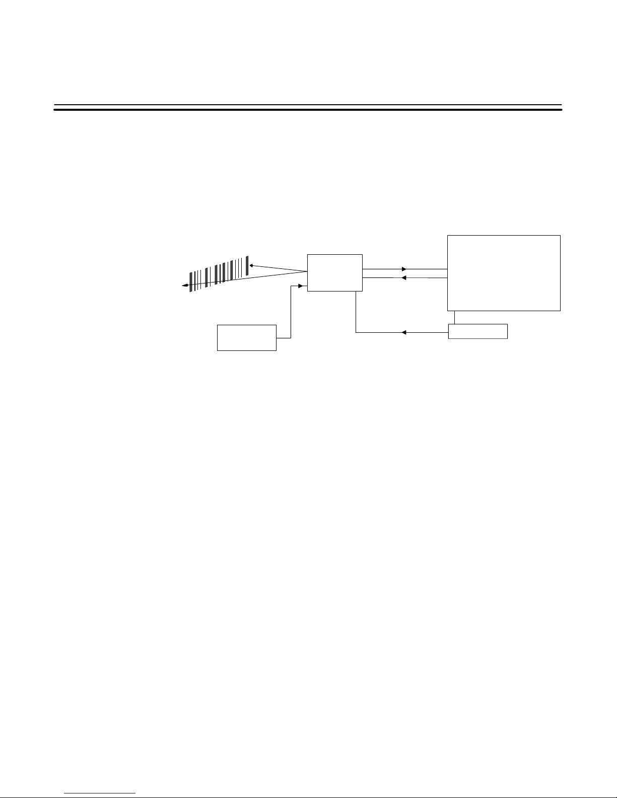
The major components of the system are the SCANTEAM 3700 Machine Mount CCD
and the host instrument or equipment. Electrical power is generally supplied to the 3700
Machine Mount CCD by the host system. Figure 2.1 shows the functional relationships
between the components of the basic system.
SCANTEAM
3700
Machine
Mount CCD
Asynchronous
Communication
2
Host System
Auxiliary Trigger
Bar Code
Provides Data Input
Aux Trigger
Triggers Decoder
Device
(Optional)
Scanning Circuitry ✺
Scans Bar Code
Decoder
Enables Scanning Circuitry
Reads Bar Code
Sends Decoded Bar Code
to Host
✺ Scanning circuitry is internal to 3700.
Figure 2.1 Basic System Operation
Power Supply
Host Application
Supplies Power to 3700 (typically)
Sends Configuration Commands
Sends Operational Commands
Sends Configuration Status Query
Commands
Sends Software Trigger Signal
(Optional)
System Hardware Description 2–1
Page 14
2.2 General Characteristics of the 3700
2.2.1 Mechanical Layout of the 3700
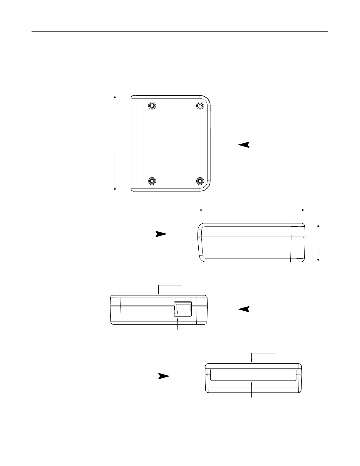
Figure 2.2 shows several views of the SCANTEAM 3700 Machine Mount CCD,
including general dimensions, the location of connectors, and the scanner window.
3.5”
[88.9]
Top View
2.9”
[73.7]
Side View
Front View
millimeters in brackets [mm]
Mounting Surface
Interface Port
(I/O Communications and Power)
Back View
Scanner Window
1.05”
[26.7]
Mounting Surface
2–2 System Hardware Description
Figure 2.2 3700 Fixed Mount CCD Dimensions
Page 15
2.2.2 Single Modular Input /Output /Power Port
The interface port is an 8–pin female modular connector used for attaching the
Asynchronous Serial Communications Interface Cable. Allows triggering capability (at
pin 2) for an external triggering device, such as an object sensor or a switch. Power and
ground connections are also on this port.
2.2.3 Audible Indicator
The beeper can be disabled by using a configuration command. Refer to Chapter 4 for
information on setting configuration commands. The beeper also sounds on power–up or
reconfiguration as an audible self–check of software configuration.
2.2.4 Mounting Inserts
Inserts are molded into the housing to retain mounting screws. Inserts are available for
metric (3.5) or SAE (#6–32) screws.
2.3 Operating Theory
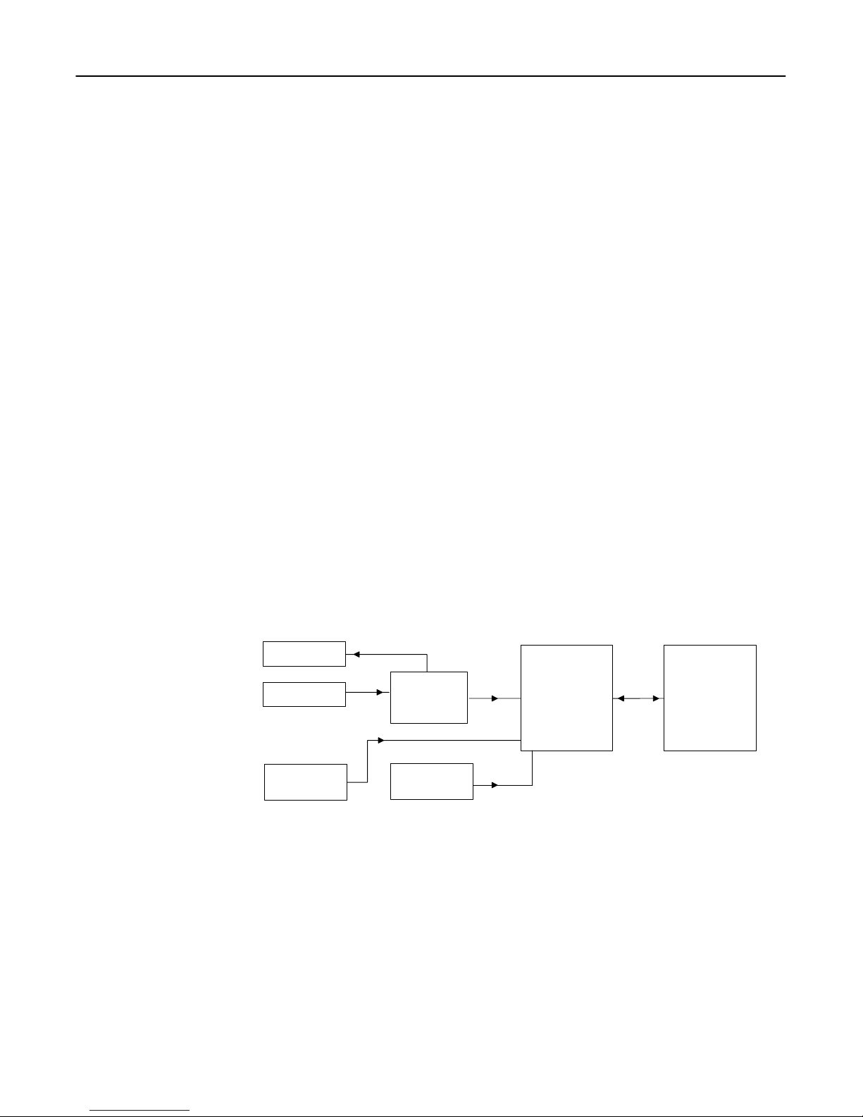
Figure 2.3 presents a block diagram of the basic SCANTEAM 3700 Machine Mount
CCD operation.
The SCANTEAM 3700 Machine Mount CCD looks for data input from the scanning
circuitry, which includes the LED reflector (illuminates the bar code target), the CCD
sensor and imaging lens (focuses the scattered optical energy from the bar code symbol),
and the peak detectors and comparator (generates a digital representation of the bar code
symbol to send to the microprocessor). Refer to Appendix A, CCD Operation and Bar
Code Scanning, for a detailed explanation of 3700 scanning circuitry operation. When
the 3700 sees a trigger, a read cycle is started. The read cycle is completed when a bar
code is read or the read timeout expires.
LED Reflector
CCD Sensor
Auxiliary Trigger
(Optional)
LED Pulse Generator
Peak Detectors
and Comparator
Second Scanner
Digital Input
(Optional)
Decode
RS–232
Communications
Figure 2.3 Basic Scanner/Decoder Operation
Note: A trigger can be a hardware trigger, such as an object sensor, or a software command,
such as a serial trigger command or continuous read trigger mode command, from the
host. Refer to chapter 4 for description of serial trigger and trigger mode commands..
During a read cycle, the 3700 evaluates scanner data for a valid bar code symbol. If a
valid bar code symbol is seen, data is placed into the output queue where it may be
transmitted to the host through the RS–232 communications port. The 3700 can
optionally be configured to send a “No Read” message when a read cycle times out.
System Hardware Description 2–3
Page 16

2.4 Scanner/Host Communication
The RS–232 communications interface of the 3700 is used for entering configuration
commands from a PC or host instrument for specific application requirements. The
communications I/O port also sends decoded bar code data to the host.
2.4.1 Communications Port
The communications port connector for the 3700 is an 8–pin female modular socket for
interfacing to the host system or other communications device. Communications
between the host system and the 3700 occur using an Asynchronous ASCII protocol.
Refer to Appendix B for a complete description of pin assignments of the RS–232
communications port.
Caution: Do not use a host communications cable with more wires connected than are
required for the application. Damage to equipment within the system may result if
the communications connection is improperly wired.
2.4.2 Asynchronous Serial ASCII Interface
The Asynchronous serial ASCII Interface operates in Full Duplex Mode. Software
configuration parameters (see Chapter 4) control Baud Rate, Parity, Data Bits, Stop Bits,
Xon/Xoff, ACK/NAK, RTS/CTS, and Pre/Postambles.
Baud rate is a means of expressing data transmission speed, where “baud” equals the
number of signal events per second (roughly equivalent to bits per second). Parity is a
means of checking character bit patterns for validity by confirming if they contain an
Even or Odd number of “1”s. The communications port can be configured to operate at
baud rates of 600, 1200, 2400, 4800, 9600, 19200, and 38400, with even, odd, or no
parity.
Data bits refers to the number of bits used to encode each ASCII character in a data
message. Stop bits refers to the number of stop bits appended to each character. The
communications port can be configured to send 7 or 8 data bits, with 1 or 2 stop bits.
Note: For proper operation the 3700 must be configured for the same baud rate, parity, number
of data bits, and number of stop bits as the connected RS–232 host device.
Xon/Xoff are control characters that refer to ASCII characters “DC1” and “DC3,”
respectively. If enabled, Xon/Xoff is a method to control data flow in the following
manner. Whenever its buffers approaches full, the device receiving communications data
sends an “Xoff” to stop data transmission. The transmitting device stops data
transmission. When its buffer approaches empty, the receiving device sends “Xon” and
the transmitting device starts sending data again. The receiving device refers to the host
instrument. Likewise, the transmitting device refers to the 3700.
Note: The SCANTEAM 3700 will respond to XON and XOFF characters from the host, but will
not send these characters.
2–4 System Hardware Description
Page 17

ACK/NAK are ASCII characters that allow the receiving device to tell the sending
device to repeat a data message that contains errors. If enabled, the 3700 expects to
receive an ACK (positive acknowledgement of data transmission) or a NAK (negative
acknowledgement of data transmission) from the host after each message is sent. If a
NAK is received, the 3700 repeats the message. After three attempts to transmit have
been made, with successive NAK from the host, the 3700 will discard the message. The
3700 responds to communication from the host with an ACK or NAK.
Pins are available at the I/O Port to support RTS/CTS handshaking. The RTS/CTS
feature may be enabled or disabled in the scanner software configuration. During
communications, the 3700 will raise RTS and wait for CTS before each transmission. In
applications where the host system does not support “handshaking,” the CTS line may be
left unconnected and the 3700 will pull it to the active state. Alternately, if CTS is left
unconnected, RTS/CTS can be disabled by configuration command.
Preambles and postambles are optional ASCII strings that precede and are appended to
each data message sent by the 3700. Typical preamble and postamble strings would
include the ASCII control characters STX (start of text), ETX (end of text), CR (carriage
return) and LF (line feed). An identification character to indicate the type of bar code
read and source scanner port is included in the standard scanner software configuration.
2.4.3 Hardwire Pinouts
The following signals not related to communications are available by hardwiring to the
motherboard (factory ordered with all cable requirements). See Appendix B for the full
lising of available pinouts.
• Pin 1 Boot Strap
• Pin 2 Dig In – Auxiliary
• Pin 3 Reset
• Pin 4 IND – Good Read
Auxiliary Trigger
The scanned data input can be controlled by an external triggering device connected to
the Trigger/Enable line (pin 2 of the Communications port). The actual trigger can be as
simple as a foot actuated relay switch and as sophisticated as an optical sensor.
The Trigger/Enable line action depends on output mode, as follows:
• Bar/Space Output Mode – continuous scan while active
• ASCII Output Mode – read while active – transmit on timeout.
System Hardware Description 2–5
Page 18

2.5 Power Requirements
DC operating voltage is +5 volts and consumes approximately 200 milliamps when
scanning. Refer to Appendix B for a complete description of voltage range, current
consumption levels, and pin assignments.
2–6 System Hardware Description
Page 19

SET–UP AND INSTALLATION
3.1 Introduction
This chapter explains the SCANTEAM 3700 Machine Mount CCD set–up for use in the
design lab and a brief description of installation in a host instrument. The set–up
procedures are intended for a technician or design engineer to explore the functions and
features of the 3700 Machine Mount CCD in a hands–on setting, before the 3700 is
embedded in host equipment. The section on installation in a host instrument includes
the general mounting dimensions of the 3700.
Set–up and installation includes unpacking the unit, checking for possible damage during
shipment, and connecting the Machine Mount CCD to the host system. The host system
in the design lab will typically be a PC/DOS microcomputer with an RS–232
communications port and a serial communications program. Otherwise, the host system
is the instrument or equipment the 3700 is intended to be embedded in.
A Hand Held Products representative will provide application support if needed. Refer
to Chapter 5 for Hand Held Products’ service and technical assistance phone number(s).
3
3.2 General Preparation for Use
Upon receipt, open the carton. Keep the shipping carton since this should be used in the
event the scanner ever needs to be returned to the factory for service or repair.
Check the part numbers and confirm that each item on the packing list has been supplied.
Check that the scanner model number and any other companion products are the ones
ordered for your application. The scanner model and serial numbers are on the
identification label attached to the scanner enclosure. Refer to Figure 3.1. You may
want to record these numbers for easy reference when communicating with Hand Held
Products or your Sales Representative.
Thoroughly inspect the 3700 to determine if any damage has occurred during shipment.
Any damage should be reported immediately to the carrier that delivered the 3700.
Damage claims due to handling during shipping should be placed directly with the
carrier. Hand Held Products will quote for repair of shipment damage (refer to Chapter
5), but the final claim and negotiations with the carrier are the responsibility of the
purchaser.
When all the components of your order have been identified and checked, prepare the
3700 for service using the procedures provided in the following sections (for set–up in a
design lab or for installation in host equipment). To assure proper operation and prevent
possible damage to the 3700 or your host system, perform the following set–up
procedures in the sequence in which they are presented.
Note: Before starting the set–up or installation procedure, set the host system or computer
power switch to the “OFF” position.
Set–Up and Installation 3–1
Page 20
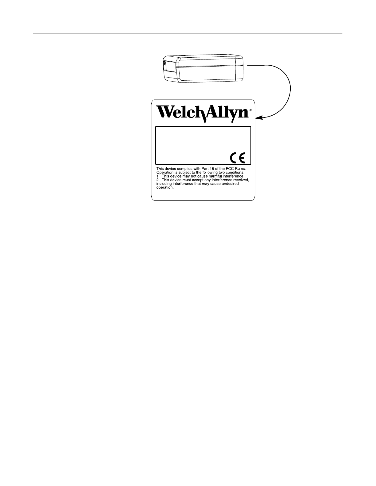
Enlarged View of Label
ST3700
NEAR CONTACT DECODED OUTPUT
ITEM# 3700-XYZ
SOFTWARE# 31203795-XYZ
DATE - S/N H-04-1234
MADE IN USA PATENT 5,294,783
www.welchallyn.com
Figure 3.1 SCANTEAM 3700 Identification Label
3.3 Set–up Procedure for Evaluation of the 3700
Caution: The 3700 contains static sensitive components. The 3700 has been designed for
internal protection against damage due to discharge. Precautions should be taken
to protect against static discharge to the 3700.
3.3.1 Preparation
Interface cables for evaluating the 3700 are available from Hand Held Products. Hand
Held Products also offers 110VAC and 220VAC to 5VDC power supplies for the 3700.
If you wish to construct your own cables, Appendix B lists the 3700 port pin
assignments.
Set–up Checklist
• SCANTEAM 3700 CCD Scanner
• SCANTEAM 3700 Input/Output/Power Cable
• 5 VDC Power Supply
• Computer with Serial I/O Port
• For I/O: may need a 25 pin to 9 pin convertor
(Refers to step 4 in 3.3.2 Set–up Procedure.)
• For I/O: may need a Null Modem adapter
(Refers to step 4 in 3.3.2 Set–up Procedure.)
• Terminal Emulation Software
(Refers to step 6 in 3.3.2 Set–up Procedure.)
3–2 Set–Up and Installation
Page 21

3.3.2 Set–up Procedure
This procedure will verify that bar code scanning and communications between the host
and the 3700 has been established.
To setup serial communications to the scanner
1) Connect the RS–232 communications (I/O) cable between the 3700 and the PC
serial port. (You may require a 25 pin to 9 pin converter and Null Modem adapter.
Contact your Hand Held Products sales representative or distributor for assistance.)
2) Connect power to the 3700. The scanner should beep once.
3) Start serial communications software program, such as PCTools Desktop (Central
Point Software), on the PC.
4) On the PC, set up the serial communications program to match the 3700 default
values:
• Baud rate = 9600
• Parity = Even
• Stop Bits = One
• Data Bits = Seven
5) The default factory scanner configuration for the SCANTEAM 3700 requires a
serial command from a host to trigger a scan. Change the trigger mode to
“Continuous Read, Send Once, Clear on Timeout” by typing <Kg , 1>. The elapsed
time between the typing of each character should not exceed 5 seconds. The
illumination LEDs should light in response to the command.
6) Confirm communications to the 3700 with the test label below. Observe that the
LED reflector is illuminated. Scan the test label“ABC123” below. The default
scanner configuration for preamble is Port ID and Code ID. Default postamble is
CR (carriage return) and LF (line feed). Observe within 3 seconds the message
“1bABC123” on the PC.
• “1” = Port ID
• “b ” = Code ID (Code 39 code ID is “b”)
• “ABC123” = The bar code label
A B C 1 2 3
This completes set–up of the SCANTEAM 3700 Machine Mount CCD for evaluation.
You are now ready to configure the 3700 to explore the functions and features.
Instructions for configuring the 3700 using configuration and operational commands are
provided in Chapter 4, Configuring the SCANTEAM 3700.
Set–Up and Installation 3–3
Page 22

3.4 Installation in the Host Instrument
Caution: The 3700 contains static sensitive components. Precautions must be taken to
eliminate potential static discharge to the 3700.
Installation in the host instrument includes the following activities:
1) Power down the host system or instrument.
2) Mount the SCANTEAM 3700 in the host instrument. The 3700 has four mounting
holes (threaded inserts). Be sure to allow access to all cable connections. Figures
3.2 and 3.3 show the general dimensions for mounting the 3700.
3) Connect the 3700 RS–232 Communication Port to the host system I/O.
4) If applicable, connect your object sensor or hardware triggering device to the 3700.
5) Power up the host system or instrument.
3–4 Set–Up and Installation
Page 23
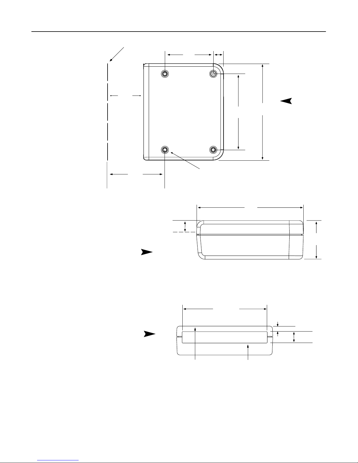
Focal Plane
REF
1.95”
[49.5]
1.75”
[44.5]
.375”
[9.5]
2.75”
[69.9]
3.5”
[88.9]
Top View
2.73”
[69.3]
Nominal Optics Center Line
Side View
Front View
.31” [7.9]
✺
Mounting Screw Location #6–32 UNC–2B or M3.5 (4 Places)
2.9”
[73.7]
1.05”
[26.7]
✺ Installation should provide adjustment to align the optical center line
on the intended target. This adjustment should account for tolerance
variation in the 3700 scanner, as well as the host equipment.
3.1” [78.7]
.2” [5.1]
.42” [10.7]
millimeters in brackets [mm]
Mounting Surface
Scanner Window
Figure 3.2 Mounting Dimensions for the 3700
Set–Up and Installation 3–5
Page 24

The 3700 Machine Mount CCD may be oriented in any way so that the beam scanning
path moves across the bar code as shown in Figure 3.3. Bar code presentation to the
scanner is important for successful scanning of the label. The first requirement is that the
beam scan path cross all bars on the label, as well a 0.25 inch quiet zone before and after
the code. The Automatic Identification Manufacturers (AIM), the industry association,
has defined orientation of the bar code label according to Figure 3.4.
Bar Code Target Moving
Perpendicular to Scan Beam
Optical Light Center Line
Mounting Surface
Optical Light Center Line
Mounting Surface
Bar Code Target Moving
Parallel to Scan Beam
Front View
Indicates relative direction
of bar code target movement
Mounting Surface
Figure 3.3 Examples of SCANTEAM 3700 Barcode Orientation
3–6 Set–Up and Installation
Page 25

PITCH OR ROLL
Rotation about the Y–axis ±7°
R
TILT
Rotation about the Z–axis
controlled by bar code
length and height
Figure 3.4 SCANTEAM 3700 Pitch, Skew and Tilt Tolerance
Bar Code Label
R
SKEW OR YAW
Rotation about the X–axis ±30°
(0 to –10° specular
reflection interference
✺ See Figure 3.5
Bar Code Label
THE ABOVE DEFINITIONS ARE FROM AIM SPECIFICATIONS
✺)
R
Bar Code Label
Rear View
R = Rotation
Bar
Code
Target
–30°
–10°
.31” [7.9]
Nominal Optics
Center Line
+30°
0°
Specular Zone
(Operation in the Specular Zone must be avoided)
Figure 3.5 Specular Reflection Interference
Set–Up and Installation 3–7
Mounting Surface
SCANTEAM
3700
Page 26

– NOM –
Focal Plane
3.5”
[88.9]
3.1”
[78.7]
1.55”
[39.4]
2°
15°
27°
.61”
[15.5]
.2”
[5.1]
2.4”
[61]
Minimum clearance required for
=
scanner illumination of target. [
Receive path/area. [
=
Top View
[ Illumination area is larger than receive area.
This completes installation of the SCANTEAM 3700 Machine Mount CCD in a host
instrument. You are now ready to configure the 3700 for your particular application.
Instructions for configuring the 3700 using configuration and operational commands are
provided in Chapter 4, Configuring the SCANTEAM 3700.
3–8 Set–Up and Installation
Side View
2°
millimeters in brackets [mm]
Figure 3.6 Scanner Illumination Clearance
Page 27

CONFIGURING THE SCANTEAM 3700
4.1 Preparation
This chapter provides instructions for configuring the software in the SCANTEAM 3700
Machine Mount CCD. The configuration process allows you to change the operating
parameters of the scanner software to explore the functions of the 3700. The
user–defined configuration is stored in volatile RAM memory and can be changed by the
user.
All communication between the host system and the 3700 Machine Mount CCD is
through the RS–232 communications interface using an Asynchronous ASCII protocol.
The host system sends commands one at a time to the 3700. During the configuration
process, there is no acknowledgement or other response from the 3700. It is important to
enter commands accurately. If a command is sent erroneously to the 3700, you may
terminate that command and send the command again. You may send configuration
status query commands to obtain a status listing of the configuration selections.
For detailed instructions on preparing the SCANTEAM 3700 for configuration, refer to
section 3.3, Set–up Procedure for Use in the Design Lab, or section 3.4, Installation in
the Host Instrument.
4
The application–specific features that can be modified using the RS–232 communication
line include the following:
• Auditory feedback for operator
• Bar code symbology may be disabled for security reasons
• Communications parameters
• Data message options
• Decoding enabled or disabled
• Fully configurable bar code symbologies and their options
• Triggering options.
Configuring the SCANTEAM 3700 4–1
Page 28

4.2 Command Conventions
The following conventions apply when entering configuration commands:
• Actual serial configuration command entries are highlighted in bold to distinguish
them from descriptive text.
• Spaces shown within command strings must not be included in the actual string;
they are for clarity only.
• Commas shown in command strings are used as item separators and are required as
place holders; except for trailing commas in abbreviated strings, which are not
required.
• Where a selection in a command string is indicated to be more than one character
(for example, the time value in the Read Timeout command) commas are never used
to separate the characters within that item.
Command Format
The command format contains the following, with the exception of two commands ✺:
• < data string >
The data string is the serial command. Send the hexadecimal equivalent of each ASCII
value when programming the 3700 from the host. An ASCII conversion chart is
provided in Appendix D.
The following three sections, 4.3, 4.4 and 4.5, explain the operational, configuration and
configuration status query commands, providing the ASCII and equivalent hex characters
for command definitions.
Note: In order to provide compatibility with drivers already written for the SCANTEAM 7300,
configuration commands that deal with multiple scanner ports in the SCANTEAM 7300
are also recognized by the SCANTEAM 3700 Machine Mount CCD. These commands
may contain port–specific data not relevant to the 3700. This extra data will be accepted,
but ignored. These items are identified in the command descriptions by a pound sign (#).
✺ The two commands, DC2 and DC4 for enabling and disabling decoding, do not
follow the above command format. They are single character commands which do
not need the “<” before or the “>” after the data byte.
4–2 Configuring the SCANTEAM 3700
Page 29

4.3 Operational Commands
Five operational commands recognized by the SCANTEAM 3700 are:
<A> – resets the 3700
DC4 – disables bar code scanning
DC2 – enables bar code scanning
<1> – serial trigger
<Z> – saves current configuration in non–volatile memory.
Explanations, ASCII and hex characters for the operational commands follow.
Reset Command <A>
COMMAND
ASCII Hex Characters
Reset <A> 3C 41 3E
Sending the operational command <A> causes the 3700 to reset. After reset the 3700
will operate according to the last configuration saved in non–volatile memory. If a valid
configuration cannot be retrieved from memory, the 3700 will operate according to the
default configuration.
Disable Decoding Command DC4
COMMAND
ASCII Hex Characters
Disable Decoding DC4 14
This is a single character command. Sending the operational command DC4 will cause
the 3700 to stop looking at bar code data.
Enable Decoding Command DC2
COMMAND
ASCII Hex Characters
Enable Decoding DC2 12
This is a single character command. Sending the operational command DC2 will allow
the 3700 to decode according to its current configuration.
Note: DC4 and DC2 are ASCII control characters. With a terminal emulation program running
on a PC, send a DC4 by holding down the CTRL key while pressing the “T” key. Send a
DC2 by holding down the CTRL key while pressing the “R” key.
Configuring the SCANTEAM 3700 4–3
Page 30

Serial Trigger Command <1>
COMMAND
ASCII Hex Characters
Serial Trigger <1> 3C 31 3E
Sending the operational command <1> sends a serial trigger to scanner port “1.” If the
Trigger Mode for Port “1” is set to allow serial triggers, the 3700 enables the Machine
Mount CCD and attempts to read a bar code.
Trigger Mode, a configuration command, is described in section 4.4.
Serial Trigger Command <2>
COMMAND
ASCII Hex Characters
Serial Trigger <2> 3C 32 3E
Sending the operational command <2> sends a serial trigger to scanner port “2.” If the
Trigger Mode for Port “2” is set to allow serial triggers, the 3700 enables the auxilliary
wand input port. The hardware configuration to support this port is optional.
Save Configuration Command <Z>
COMMAND
ASCII Hex Characters
Save Configuration <Z> 3C 5A 3E
Sending the operational command <Z> causes the current configuration to be saved in
non–volatile memory.
4–4 Configuring the SCANTEAM 3700
Page 31

4.4 Configuration Commands
Fifteen configuration commands recognized by the SCANTEAM 3700 are:
Ka – sets communication port
Kd – sets preamble
Ke – sets postamble
Kf – sets communications protocol
Kg – sets trigger mode
Kh – sets read timeout
Kk – sets no read message
Km – sets votes
Kp – sets Code 39
Kq – sets Codabar
Kr – sets I 2 of 5
Ks – sets UPD A/E and EAN 8/13
Kt – sets Code 128
Ku – sets beeper mode
Kv – scan rate
Explanations and ASCII characters for the configuration commands follow.
Note: The commands in this section are shown in ASCII format only. Refer to Appendix D for
an ASCII conversion chart.
Format for a Configuration Comand
<K mode_global , mode_port_1 , mode_port_2>
(2)
(3) (4) (5)
(1)
(1) Configuration commands start with “<” and end with “>.”
(2) Configuration commands include “K” as the start of the command text string. The
“K” must be upper case.
(3) The next letter in the command string defines the function and must be lower case.
(4) Where applicable, the “mode_global” portion of the command defines the selection
for the particular command (for both scanner inputs) unless specified otherwise in
the following mode portions of the command.
(5) “Mode_port_1” and “mode_port_2” refer to the configuration for the particular
scanner input. The 3700 CCD is port 1, and so is controlled by Mode 1. A second
(optional) external digital scanner input is configured as Mode 2.
Note: Default configuration indicated by asterisk “*” following default configuration. Default
options (if applicable) will follow in parenthesis.
(6) No more than five (5) seconds may pass between keystrokes or the decoder will not
recognize the command as a single string of characters.
(7) If an incorrect keystroke is entered, end the string with a “>” and enter the string
over from the beginning.
Configuring the SCANTEAM 3700 4–5
Page 32

Set Communications Port Command Ka
COMMAND
<Ka baud, parity, stop bits, data bits>
Parameter ASCII Option
Baud 0 600
1 1200
2 2400
3 4800
4 9600 *
5 19,200
6 38,400
Parity 0 none
1 even *
2 odd
Stop Bits 0 one *
1 two
Data Bits 0 seven *
1 eight
Sending the configuration command Ka sets the communications port parameters. Baud
rate, parity, stop bits and data bits may be selected. For example, if you wanted to set the
baud rate to 2400, the parity to none, the stop bits to two, and the data bits to eight; you
would send the following command: <Ka 2, 0, 1, 1>. If you only wanted to set the
baud rate to 4800, leaving the other parameters unchanged, you could send the following
abbreviated command: <Ka 3>. If you only wanted to set the stop bits to two, leaving
the other parameters unchanged, you could send the following command: <Ka , , 1>.
The default setting is 9600 baud, even parity, one stop bit, and seven data bits.
Tip: The Ka command does not become effective until the 3700 is reset. Since reset
causes the 3700 to use the configuration saved in non–volatile memory, the Ka
command should be followed by a Save Configuration command <Z> and a Reset
command <A>.
4–6 Configuring the SCANTEAM 3700
Page 33

Set Preamble Command Kd
COMMAND
<Kd enable, data>
Parameter ASCII Option
Enable 0 no
1 yes * (Port ID, Code ID)
Data one to four ASCII characters
Sending the configuration command Kd sets the preamble characters. The preamble
option may be enabled or disabled; if enabled, up to four preamble characters may be
defined. Any ASCII character can be specified except NUL, ACK, NAK, DC1, DC2,
DC3, DC4 or DEL. The character SUB should only be used as the first character in a
pair, with the second character being either a 1 or a 2. SUB 1 causes the 3700 to include
the Port ID in the preamble, while SUB 2 specifies that the Code ID should be included.
Table 4.1 lists the Code ID values. The default setting is preamble enabled, Port ID and
Code ID characters sent with data strings.
Tip: When character pairs SUB 1 and SUB 2 are specified in the preamble, the SUB
characters are not counted toward the maximum number of ASCII characters
allowed (four).
Code ID Value
Definition
a Codabar
b
e
j
Code 39
Interleaved 2 of 5
Code 128
c UPC
d
SPACE
EAN
No code
Table 4.1 SCANTEAM 3700 Code ID Values
Configuring the SCANTEAM 3700 4–7
Page 34

Set Postamble Command Ke
COMMAND
<Ke enable, data>
Parameter ASCII Option
Enable 0 no
1 yes * (CR, LF)
Data one to four ASCII characters
Sending the configuration command Ke sets the postamble characters. The postamble
option may be enabled or disabled; if enabled, up to four postamble characters may be
defined. Any ASCII character can be specified except NUL, ACK, NAK, DC1, DC2,
DC3, DC4 or DEL. The character SUB should only be used as the first character in a
pair, with the second character being either a 1 or a 2. SUB 1 causes the 3700 to include
the Port ID in the postamble, while SUB 2 specifies that the Code ID should be included.
Port ID is always 1. Table 4.1 lists the Code ID values. The default setting is postamble
enabled, CR and LF characters sent with data strings.
Tip: When character pairs SUB 1 and SUB 2 are specified in the postamble, the SUB
characters are not counted toward the maximum number of ASCII characters
allowed (four).
4–8 Configuring the SCANTEAM 3700
Page 35

Set Communications Protocol Command Kf
COMMAND
<Kf mode>
Parameter ASCII Option
Mode 0 Disable RTS/CTS *
Disable XON/XOFF *
Disable ACK/NAK *
Mode 1 Enable RTS/CTS
Disable XON/XOFF
Disable ACK/NAK
Mode 2 Disable RTS/CTS
Enable XON/XOFF
Disable ACK/NAK
Mode 3 Enable RTS/CTS
Enable XON/XOFF
Disable ACK/NAK
Mode 4 Disable RTS/CTS
Disable XON/XOFF
Enable ACK/NAK
Mode 5 Enable RTS/CTS
Disable XON/XOFF
Enable ACK/NAK
Mode 6 Disable RTS/CTS
Enable XON/XOFF
Enable ACK/NAK
Mode 7 Enable RTS/CTS
Enable XON/XOFF
Enable ACK/NAK
Sending the configuration command Kf sets the communications protocol. The default
setting is Mode 0, with RTS/CTS, XON/XOFF, and ACK/NAK disabled.
Configuring the SCANTEAM 3700 4–9
Page 36

Set Trigger Mode Command Kg
COMMAND
<Kg mode_global, mode_port_1, mode_port_2, #>
Parameter ASCII Option
Mode 0 Continuous Read
Mode 1 Continuous Read, Send Once, Clear on Timeout
Mode 2 External Trigger, Read While Active
Mode 3 External Trigger, Read Once
Mode 4 Serial Trigger
Mode 5 Serial Trigger or External Trigger,
Read Once *
Sending the configuration command Kg sets the trigger mode. The command string is
interpreted left to right. For example, if you send the following command: <Kg 4, 0>,
both ports will be set to mode 4, then port 1 changes back to mode 0. Likewise, if you
send the following command: <Kg , 0, 4>, port 1 is set to mode 0 and port 2 is set to
mode 4. Both commands have the same end result; port 1 will be in continuous read
mode and port 2 will be in serial trigger mode. The default setting is Mode_global 5,
selecting a serial trigger or an external trigger, one read.
Tip 1: Careful consideration must be taken when configuring multiple ports to a
continuous trigger mode. The 3700 decodes from only one port at a time. With
multiple ports triggered, the 3700 will select each in turn and attempt to read. If
no bar code label is present at the selected port, the 3700 will wait for read
timeout to expire before stepping to the next port. If read timeout is set to a value
near or greater than the time it takes a bar code label to pass by a scanner, then
the label will often be missed.
Set Read Timeout Command Kh
COMMAND
Parameter
Mode 0 Timeout Ends a Read Attempt * (150)
Time one to five ASCII digits,
Sending the configuration command Kh sets the read timeout. One to five ASCII digits
in the range of 10 to 65,000 determine the number of 10ms increments of time that the
3700 will, once triggered, wait while attempting to read from a port. For example, if you
wanted to set port 1 to timeout ends a read attempt after 100ms; you would send the
following command: <Kh , , 0, 10>. Port 2 is not changed. The default setting is
Mode_global 0 and Time_global 150 (150 x 10 msec = 1.5 seconds).
4–10 Configuring the SCANTEAM 3700
<Kh mode_global, time_global, mode_port_1, time_port_1,
mode_port_2, time_port_2, #, #>
ASCII Option
range of 10 to 65000
Page 37

Set No Read Message Command Kk
COMMAND
<Kk enable, data>
Parameter ASCII Option
Enable 0 no
1 yes * (NR)
Data one to seven ASCII characters
Sending the configuration command Kk sets the no read message. Any ASCII character
can be specified except NUL, ACK, NAK, DC1, DC2, DC3, DC4 or DEL. The default
setting is NR (no read).
Tip: The No Read Message is not sent for scanner ports that are configured for a
continuous trigger mode.
Set Votes Command Km
COMMAND
<Km data_global, data_port_1, data_port_2, #>
Parameter
ASCII Option
Data one or two ASCII digits
range of 1 to 31 * (3, 1)
Sending the configuration command Km sets the votes. One or two ASCII digits in the
range of 1 to 31 determine the number of consecutive identical decodes required for a
valid read. A selection of 1 means that no voting will take place. The default setting is
Data_port_1, 3 and Data_port_2, 1, which means voting is set to 3 for port 1 and set to 1
for port 2.
Tip: When using the voting feature for additional decode security, a value of three is
generally adequate in most applications.
Configuring the SCANTEAM 3700 4–11
Page 38

Set Code 39 Command Kp
COMMAND
<Kp enable, require checksum, send checksum, minimum
length, maximum length>
Parameter
ASCII Option
Enable 0 no
1 yes *
Require Checksum 0 no *
1 yes
Send Checksum 0 no *
1 yes
Minimum Length Set from 1 to 48 * (1)
Maximum Length Set from 1 to 48 * (48)
Sending the configuration command Kp sets Code 39 and all its parameters:
enable/disable, require checksum, send checksum, minimum length, and maximum
length. The default setting is Code 39 enabled, doesn’t require or send checksum,
minimum length 1, and maximum length 48.
Set Codabar Command Kq
COMMAND
<Kq enable, send start/stop, minimum length, maximum
length>
Parameter
ASCII Option
Enable 0 no
1 yes *
Send Start/Stop 0 no
1 yes *
Minimum Length Set from 1 to 60 * (6)
Maximum Length Set from 1 to 60 * (60)
Sending the configuration command Kq sets Codabar and all its parameters:
enable/disable, send start/stop, minimum length, and maximum length. The default
setting is Codabar enabled, send start/stop, minimum length 6, and maximum length 60.
4–12 Configuring the SCANTEAM 3700
Page 39

Set I 2 of 5 Command Kr
COMMAND
<Kr enable, require checksum, send checksum,
minimum length, maximum length>
Parameter
ASCII Option
Enable 0 no *
1 yes
Require Checksum 0 no *
1 yes
Send Checksum 0 no *
1 yes
Minimum Length Set from 2 to 80 * (6)
Maximum Length Set from 2 to 80 * (80)
Sending the configuration command Kr sets I 2 of 5 and all its parameters:
enable/disable, require checksum, send checksum, minimum length, and maximum
length. The default setting is I 2 of 5 disabled, doesn’t require or send checksum,
minimum length 6, and maximum length 80.
Tip 1: To require a fixed length, set the minimum and maximum lengths to the same
value.
Tip 2: An Interleaved 2 of 5 symbol must always have an even number of characters
encoded in it. However, if you have configured the 3700 to require a checksum but
not send the checksum, the 3700 will reduce the number of characters output by
one to an odd value. The minimum and maximum lengths will be checked after
the checksum is removed and so must be set to allow a symbol length that is one
less than actually encoded in the label to be read.
Set UPC A/E, EAN 8/13 Command Ks
COMMAND
<Ks enable UPC, enable EAN>
Parameter ASCII Option
Enable UPC 0 no
1 yes *
Enable EAN 0 no
1 yes *
Sending the configuration command Ks sets UPC A/E and EAN 8/13 to enable or
disable. The default setting is UPC A/E and EAN 8/13 enabled.
Configuring the SCANTEAM 3700 4–13
Page 40

Set Code 128 Command Kt
COMMAND
<Kt enable, minimum length, maximum length>
Parameter ASCII Option
Enable 0 no
1 yes *
Minimum Length Set from 1 to 80 * (1)
Maximum Length Set from 1 to 80 * (80)
Sending the configuration command Kt sets Code 128 and all its parameters:
enable/disable, minimum length, and maximum length. The default setting is Code 128
enabled, minimum length 1, and maximum length 80.
Set Beeper Mode Command Ku
COMMAND
<Ku mode_global, mode_port_1, mode_port_2, #>
Parameter
ASCII Option
Mode 0 Disable beeper *
Mode 1 Enable beeper on valid read
Mode 2 Enable beeper on failed read
Sending the configuration command Ku sets the beeper mode. For example, if you
wanted to enable the beeper for good reads on port 1; you would send the following
command: <Ku , 1>. The default setting is Mode_global 0, with beeper disabled.
Set Scan Rate Command Kv
COMMAND
<Kv rate, reserved, reserved>
Parameter
ASCII Option
Rate 0 50 scans per second
Rate 1 100 scans per second
Rate 3 200 scans per second
The Kv command has been retained in the 3700 for compatibility with the SCANTEAM
3600, but the 3700 scan rate is fixed at the time of manufacture and cannot be changed
by the Kv command. The <Kv?> status request (see next section) will report the scan
rate setting.
4–14 Configuring the SCANTEAM 3700
Page 41

4.5 Configuration Status Query Commands
The configuration status query commands are used to obtain a status listing of the
configuration command selections. You may request a listing of the entire series of
individual configuration status messages or you may request the status of a single
configuration status message be output to your host system or terminal. Descriptions and
ASCII characters for the configuration commands follow.
Note: The commands in this section are shown in ASCII format only. Refer to Appendix D for
an ASCII conversion chart.
The following command causes the entire series of individual configuration status
messages to be output to the host system:
<?> – configuration query.
Fifteen configuration status query commands recognized by the SCANTEAM 3700 are:
<Ka?> – communications port status
<Kd?> – preamble status
<Ke?> – postamble status
<Kf?> – communications protocol status
<Kg?> – trigger/enable mode status
<Kh?> – read timeout status
<Kk?> – no read message status
<Km?> – votes status
<Kp?> – Code 39 status
<Kq?> – Codabar status
<Kr?> – Interleaved 2 of 5 status
<Ks?> – UPC, EAN status
<Kt?> – Code 128 status
<Ku?> – beeper status
<Kv?> – scan rate status
Each configuration query will cause the current status of the selected option to be output
in a format identical to the configuration command string itself, except that global fields
are excluded. For example, if the trigger mode_global is set to 5 <Kg?> will result in
<Kg , 5, 5> being output by the 3700.
Except for the Communication Port Command, configuration commands take effect
immediately upon receipt by the 3700. Therefore most configuration commands can be
verified as having been received by the 3700 by immediately following the command
with a status query. For the Communications Port Command to become effective, the
command must be followed by a <Z><A> (save configuration and reset the 3700
commands) since the port is only initialized upon a reset. Since the 3700 reports the
current configuration of the port itself, the status query <Ka?> will not indicate if a
Communications Port Configuration Command has been received correctly until the
<Z><A> has been received.
All status output strings will include the current preamble and postamble. Thus if the
preamble is set to DC1 and the postamble to DC3 then a postamble status query <Ke?>
will result in the output string DC1<Ke1,DC3>DC3. The receiving system must be able
to handle the embedded DC3 and not treat it as the termination of the string.
Configuring the SCANTEAM 3700 4–15
Page 42

4.6 Default Operating Parameters
The SCANTEAM 3700 is configured at the Hand Held Products factory with standard
(default) operating parameters. The default configuration can be used as is or changed
(reconfigured) by downloading new parameters over an RS–232 communications line
from a host instrument. The default configuration settings are listed below.
Default Configuration Settings
• ACK / NAK Disabled
• Baud Rate 9600
• Beeper Mode Disable beeper
• Data Bits 7
• No Read Message “NR”
• Parity Even
• Postamble CR LF
• Preamble Port ID Code ID
• Read Timeout Timeout ends a read attempt, 1.5 seconds
• RTS/CTS Disabled
• Stop Bit 1
• Trigger Mode Serial Trigger or External Trigger, Read Once
• Votes Voting set to 3 for port 1 and set to 1 for port 2
• XON/XOFF Disabled
Default Configuration: Symbology Settings
• Codabar Enabled
Send Start/Stop Yes
Minimum Length 6
Maximum Length 60
• Code 39 Enabled
Require Checksum No
Send Checksum No
Minimum Length 1
Maximum Length 48
• Code 128 Enabled
Minimum Length 1
Maximum Length 80
• I 2 of 5 Disabled
Require Checksum No
Send Checksum No
Minimum Length 6
Maximum Length 80
• UPC A/E, EAN 8/13 Enabled
4–16 Configuring the SCANTEAM 3700
Page 43

SERVICE/TECHNICAL ASSISTANCE
5.1 Maintenance
The Hand Held Products SCANTEAM 3700 Machine Mount CCD Bar Code Scanner
and Decoder is designed to provide reliable and efficient operation, requiring no routine
maintenance. The 3700 has no moving physical parts. Convection air flow serves to
cool the unit. Maintenance, therefore is related to troubleshooting and replacement of the
3700 Machine Mount CCD.
Troubleshooting procedures are described in the following section. Section 5.4 provides
procedures for removing and replacing a SCANTEAM 3700 Machine Mount CCD.
5.2 Troubleshooting Guide
This section describes procedures for identifying problems that prevent the SCANTEAM
3700 from operating normally. Field repair procedures include the following:
• Power supply troubleshooting
• 3700 Machine Mount CCD troubleshooting
5
5.2.1 Troubleshooting Hints
If there is no power to the 3700 Machine Mount CCD, check the following:
• Host power supply output to the 3700. Check that the output voltage from the host
is +5 VDC. If the voltage isn’t present or is out of range, there may be a problem
with power distribution from the host system. Appendix B provides the specific
voltage range.
• If there is no output voltage, check to be sure the host instrument power switch is set
to “ON”; if this switch is on and there is no output voltage, there may be a problem
with the host power supply.
• Check all cables for secure connections and continuity (with an ohm/volt/meter).
Warning: Only a qualified person should attempt to replace a power supply.
Service/Technical Assistance 5–1
Page 44

5.2.2 Diagnostic Procedure
The SCANTEAM 3700 Machine Mount CCD may be reset to the last saved
configuration parameters by issuing a Reset Command. (A list of these parameters may
be found on in section 4.6 and C.4.)
• To perform a Reset Command, send an <A> serial command to the 3700. This
action causes all data in memory to be erased and the current user configuration
parameters to be loaded from non–volatile memory. In the absence of a user
configuration, the default configuration is loaded into memory. This action allows
the user to clear memory of any corrupt data from scanned data.
5.2.3 Troubleshooting Checklist
Problem
3700 does not scan.
3700 is not reading bar
code.
Beeper does not come on.
Data is not transmitted.
Possible Cause
1) Loose I/O communications cable.
2) Trigger mode not configured correctly.
3) Not triggered.
1) Bar code symbol type is disabled.
2) Symbol length is out of range.
3) Symbol does not contain a valid
checksum character.
4) Bar code is bad, damaged or out of spec.
5) Window is scratched or dirty.
1) 3700 is not decoding.
2) Good read is disabled.
1) Loose I/O communications cable.
2) 3700 is waiting for clear to send (CTS).
3) 3700 is waiting for XON.
Solution
1) Connect cable.
2) Configure the 3700 for the proper trigger
mode and read timeout value.
3) Provide trigger consistent with the trigger
mode configuration.
1) Enable the symbology.
2) Configure the 3700 for correct length.
3) Configure the 3700 to not require checksum
or use a label with a valid checksum.
4) Replace bar code.
5) Clean window.
1) See “3700 is not reading bar code.”
2) Configure the 3700 for desired good read
operation.
1) Connect cable.
2a) Have the receiving equipment generate CTS.
2b)Disconnect CTS signal allowing the 3700 to
force CTS to the active state.
3a) Send an XON to the 3700.
3b)Configure the 3700 to disable XON.
Data message is missing
or garbled.
Baud rate, parity, stop bits or data bits is
wrong.
Table 5.1 SCANTEAM 3700 Troubleshooting Checklist
5–2 Service/Technical Assistance
Configure the 3700 for the proper
communications parameters.
Page 45

5.3 Obtaining Factory Service
Hand Held Products provides service for all its products through a service center located
at its manufacturing facilities in Skaneateles, New York. To obtain warranty or
non–warranty service, return the unit to Hand Held Products (postage paid) with a copy
of the dated purchase record attached.
In the United States, please contact the Hand Held Products’ Product Service Department
at the address/telephone number listed below to obtain a Return Material Authorization
number (RMA #).
Main Office
Welch Allyn Data Collection, Inc. (d/b/a Hand Held Products)
4619 Jordan Road
P.O. Box 187
Skaneateles Falls, New York 13153–0187
Product Service Department
Telephone: (315) 685–4278 or 685–4360
Fax: (315) 685–4156
For service in Europe, please contact your Hand Held Products’ representative (at the
address that follows) or your local distributor.
European Office
Hand Held Products, Ltd.
Hondsruglaan 87 D
5628 DB Eindhoven
The Netherlands
Telephone: Int+ 31 40 242 4486
Fax: Int+ 31 40 242 5672
United Kingdom Office
Hand Held Products (UK) Ltd.
Dallam Court
Dallam Lane
Warrington
Cheshire WA2 7LT
United Kingdom
Telephone: Int+44 (0) 1 925 240055
or Int+353 1 216 0070
Fax: Int+44 (0) 1 925 631280
or Int+353 1 295 6353
For service in Asia, please contact your Hand Held Products’ representative (at the
address that follows) or your local distributor.
Asia/Pacific Office
Hand Held Products
10/F Tung Sun Commercial Centre
194–200 Lockhart Road
Wanchai, Hong Kong
Telephone: Int+852–2511–3050 or 2511–3132
Fax: Int+852–251–1355
For service in Japan, please contact your Hand Held Products’ representative (at the
address that follows) or your local distributor.
Service/Technical Assistance 5–3
Page 46

Japan Office
Hand Held Products
Bon Marusan 8F
3–5–1 Kanda–Jinbocho
Chiyoda–ku
Tokyo 101, Japan
Telephone: Int+81–3–5212–7392
Fax: Int+81–3–3261–7372
For service in Latin America, please contact your Hand Held Products’ representative (at
the address that follows) or your local distributor.
Latin America Office
Hand Held Products
5150 North Tamiami Trail
Suite 302
Naples, FL 34103–2821
Telephone: (941) 263–7600
Fax: (941) 263–9689
5.4 Help Desk
If you need assistance installing or troubleshooting your scanner, please call your
Distributor or the nearest Hand Held Products technical support office:
North America:
Telephone: (315) 685–2476 (8 a.m. to 6 p.m. EST)
Fax number: (315) 685–4960
E–mail: support@handheld.com
Europe:
Telephone–
European Ofc: Int+31 40 242 4486
U.K. Ofc: Int+44 1925 240055
E–mail: support@handheld.com
Asia:
Telephone: Int+852–2511–3050 or 2511–3132
E–mail: support@handheld.com
5.3.1 Service Under Warranty
All Welch Allyn bar code products carry a one (1) year warranty (from date of
shipment). The specific Limited Warranty coverage for the SCANTEAM 3700 Machine
Mount CCD is described near the end of this manual. Warranty service may be obtained
by contacting the Welch Allyn Customer Service Group.
5.3.2 Out Of Warranty Service
Factory service is also available for out of warranty products on a time and materials or
fixed price basis. The scanner/decoder should be returned (postage paid) for repair only
after obtaining a Return Material Authorization (RMA) from a Customer Service
Representative. When out of warranty product service is required, you will be advised of
a “not to exceed” price for repair when the Return Material Authorization is requested.
5–4 Service/Technical Assistance
Page 47

The following information is required to process an RMA for the product and should be
available for the Service Representative. It is located on the manufacturers label attached
to the box the SCANTEAM 3700 was shipped in.
Model Number
Serial Number
Date of Manufacture
Note: The Welch Allyn Customer Service Group cannot accept materials that are returned
without an RMA number.
When out of warranty service is required the Customer Service Representative will
request a Purchase Order Number in the amount of the “not to exceed” price for repair.
However, customers will be billed only for the actual service costs.
5.4 SCANTEAM 3700 Removal/Replacement
The application intention of the 3700 makes it a component of the host controlled
instrument. Power to the host system must be turned off before removing the 3700
Machine Mount CCD. Removing the 3700 involves reversing the steps that you
followed during installation (Chapter 3).
Caution: Some circuits in the 3700 Machine Mount CCD are sensitive to electrostatic
discharge. Be sure you are properly grounded before removing the 3700 from the
host system.
Note: Set the host instrument power switch to the “OFF” position.
Step 1: Disconnect the data communications/ power cable between the 3700 Machine
Mount CCD and the host system (see Chapter 2, Figure 2.2 for the exact
location of the port on the 3700).
Step 2: Using a screwdriver, remove the mounting screws, if applicable, from the 3700
Machine Mount CCD.
Step 3: Remove the 3700 Machine Mount CCD and place it immediately into an
antistatic container or an antistatic bag.
This completes the 3700 Machine Mount CCD removal procedure. For replacement
vinstructions, please follow the set–up and installation procedures in Chapter 3.
Service/Technical Assistance 5–5
Page 48

5–6 Service/Technical Assistance
Page 49

CCD OPERATION AND BAR CODE SCANNING
A.1 Objectives
This appendix describes:
• Reading and decoding a bar code symbol.
• Overview of how the SCANTEAM 3700 works, including a scanner diagram with
the main decoding elements listed.
• In–depth discussion of the operation of the scanner, including a block diagram and
discussion of the internal parts of the scanner, and a timing sequence diagram.
• Bar code basics and scanning tips.
A.2 Scanning and Decoding a Bar Code Symbol
The body of the SCANTEAM 3700 houses all the scanning elements, and
decoding/interface elements. Refer to Figure A.1.
A
LED
Reflector
Bar
Code
Symbol
Aperture
Lens
LED Pulse
Generator
CCD
Sensor
Bar Code
Label
Image
Decoding/Interface
Power Supply,
Digitizing,
Microprocessor,
Signal
Processing,
and Control
Circuitry
Cable
Modular
Connector
Pixel
Array
Figure A.1 Main Elements of the 3700 CCD Bar Code System
The SCANTEAM 3700 performs the following steps when scanning and decoding a bar
code symbol:
1. The scanner turns the LEDs (Light Emitting Diodes) inside the scanner ON, and the
light from the LEDs illuminate the bar code symbol.
CCD Operation and Bar Code Scanning A–1
Page 50

2. The black bars on the symbol absorb the LED light, while the white spaces scatter
the LED light.
3. A portion of the scattered light re–enters the scanner’s optical system and is detected
by the pixels of the CCD (Charged Coupled Device).
4. The CCD converts the returned light into a sequence of electrical pulses with
amplitude proportional to the energy level of the scattered light.
5. The digitizer converts the analog light signal to a bit serial representation of the bar
code symbol. The width of the binary signal pulse being proportional to the width of
the bars and spaces of the bar code symbol.
6. The Decoding Circuitry decodes the digitized pulses into characters of data
representative of the bar code symbol.
7. After a successful decode is complete, a beeper is sounded (if enabled to indicate a
Good Read). The decoded information is transmitted to the host.
8. Depending upon the trigger chosen, the scanner either continuously initiates another
scan cycle or waits for the next trigger to scan.
LED Reflector
The bar code symbol is illuminated with a bank of LEDs with a proprietary reflector.
The LEDs are pulsed, strobing illumination, to stop relative motion of the scanner and
the label.
CCD Sensor
The optical energy scattered from the bar code symbol is focused with a custom lens onto
the pixel array of the CCD sensor.
The switching transients from the CCD are removed with analog filters. This filtered
signal is then an analog representation of scattered light incident on the CCD.
Peak Detectors and Comparator
The positive and negative peak detectors retain the signal level associated with the
minimum black and maximum white reflectances respectively. The comparator
threshold is then set at a point between the black and white peak reflectance levels. The
threshold level and the analog representation of the scattered light are then compared
with a comparator, generating the bit serial digital representation of the bar code symbol.
A–2 CCD Operation and Bar Code Scanning
Page 51

Microprocessor
The microprocessor controls the generation of timing signals required for the operation
of the SCANTEAM 3700 device. Additionally it monitors the digital output of the
device, configures the operating parameters sent through serial commands (as required),
and decodes the scanned bar code data.
Timing Sequence
Figure A.2 illustrates the timing sequence for the SCANTEAM 3700.
Bar Code Symbol
Being Scanned
Timing
Shift Out Analog Data
Illumination
Analog Signal from CCD Array
White
Black
Digital Data Out
White
Black
Decoded Data (Decoded Output Only)
Figure A.2 SCANTEAM 3700 Timing Sequence
CCD Operation and Bar Code Scanning A–3
Page 52

A.3 Bar Code Basics and Scanning Tips
A Closer Look At Bar Code Symbols
The illustration at the right shows a typical bar code
symbol. If you look at it closely, you’ll see it is
composed of a series of dark lines (bars) and white
areas (spaces) of various widths. By arranging these
bars and spaces in a certain order, it is possible to
represent, or “encode” letters, words and numbers.
You may also print the numbers represented by the bar code symbol on the label. These
human readable characters allow you to know exactly what information the scanner is
sending to the register or terminal. The human readable characters under the bar code
symbol also allow you to key in information in case the bar code symbol is not readable.
The blank area located just before and just after the bar space pattern is called the “quiet
zone.” It is placed on the symbol so the scanner knows exactly where the bar code
begins and ends. It is important to remember where the quiet zone is located so you can
scan accurately.
0
42000 06200
Bar Code Scanning
The purpose of the bar code scanner is to “read” the image formed by the bars and
spaces. A signal sends the information printed on the bar code symbol to the terminal.
Several types of scanners are in use today. The most common types include the wand
scanner, the laser scanner, and the CCD scanner. All scanners use optical systems which
are protected by “windows” at the scanning end to read the bar code symbol. On wand
scanners, the window is located in the tip. Laser and CCD scanners have a larger and
more noticeable viewing “window.” It is important to keep these optics clean, because
just like the lenses on reading glasses, if they become dirty, scratched or smudged, they
won’t work properly.
If your scanner is attached to a decoder (or it is also a decoder), the decoder may have a
beeper that will let you know when a scan has been performed properly and that the bar
code has been read accurately. After you’ve scanned a symbol, listen for a single beep,
(called a “good read” beep). This lets you know that the bar code information has been
received by the terminal. If you don’t hear the single beep or if you hear several beeps, it
means the symbol is unacceptable to the decoder, and the terminal has not received the
bar code information. If that happens, try scanning the symbol again.
Before using any scanner, make sure the symbol is of good quality and that the optic area
of your scanner is clean. Any dirt or specks in the bar code symbol or on the scanner
optics may prevent it from reading accurately. Even a symbol that is smudged during
printing, or gets wrinkled when it is applied to an object can cause a reading problem. If
you can’t get a good read beep or you begin to receive error beeps, be sure to check the
scanner optics and the symbol. The decoder may need to enable the beeper, either with a
hardware configuration or with a software command.
A–4 CCD Operation and Bar Code Scanning
Page 53

TECHNICAL SPECIFICATIONS
B.1 Scanner Performance
The SCANTEAM 3700 performance has been measured in terms of the first bar
elongation/contraction and inner bar (space) elongation/contraction when scanning
Welch Allyn test targets. If you need more information on these measurements, contact
your Welch Allyn representative.
B.2 Optical Specifications
Scanning Direction: Single Line (Unidirectional)
Scan Rate: 100 scans per second
See chart below.
B
Scan Speeds
Scans/Second
100 375 9500
Lateral Motion Sensitivity: 5 inches per second (254mm/sec)
Scan Width: 2.4 inches [61mm] at contact
Approximate Lateral Scan Speed
mm/SecInch/Sec
3.5 inches [89mm] maximum
Technical Specifications B–1
Page 54

Focal Distance (selected at time of order) from scanner window:
Focal Distance
0.6 inches [15mm] with a 3 inch [76mm] maximum scan width
1.95 inches [50mm] with a 3.5 inch [89mm] maximum scan width
3.2 inches [81.3mm] with a 3.5 inch [89mm] maximum scan width
Maximum Scan Width
MRD (minimum reflective difference): 37.5%
Tilt Angle: Controlled by bar code length and height
(See Figure 3.4)
Skew Angle: +30 to –30 degrees (See Figure 3.4)
Specular reflection zone 0 to –10 degrees
(Operation in this zone must be avoided.)
Pitch Angle: +7 to – 7 degrees on 7.5 mil (See Figure 3.4)
Light Source (Illumination): Visible Red LED (Wavelength = 645 nm ±30)
CCD Type Standard Resolution / Standard Performance
Standard Resolution/Enhanced Performance
High Resolution/ Enhanced Performance
B–2 Technical Specifications
Page 55

B.3 Electrical Specifications
Operating Voltage: +5V+5% ✺
Operating Current: 170 to 250 mA, ✺
depending on scan rate for
Standard Resolution/ Enhanced Performance
CCD type
✺ Power for the SCANTEAM 3700 is provided by the host system.
Communications Port Connector Pin Assignments:
See chart below.
110
10–Pin Modular Connector
Communications Port
Pin Signal
1
2
3
4
5
6
7
8
9
10
✤ State depends on use
Hardwire Option:
See chart below.
Four Pads for Hardwire to
3700 Motherboard
Shield
Trigger/Enable ✤
Ground System Ground
TX Data
VCC +5VDC Power (Input)
RTS Ready to Send (Output)
CTS Clear to Send (Input)
Function
Cord Shield
Trigger Signal to Decoder
Scanner Enable (Input)
Receive Data (Input)RX Data
Transmit Data (Output)
Pin Signal
1 BTS
2 DIG IN Second Scanner Input
3 DEFAULT Reset
4 Good ReadIND
Function
Bootstrap
Technical Specifications B–3
Page 56

Indicators: Beeper.
See descriptions below.
Beeper
The good read/no read beeper indicator is configurable and can be disabled, if desired.
B.4 Environmental Specifications
Operating Temperature: 32° F to 122° F (0° C to +50° C)
Storage Temperature: –40° F to 158° F (–40° C to +70° C)
Relative Operating
and Storage Humidity: 0 to 95% (non–condensing)
Barometric Pressure: 101,000 to 69,000 Pascals
(Sea level to 3000 meters)
ESD: 15 KV ✺
✺ A drain path for ESD should be provided when installing a 3700 in the host system.
Shock (Drop Test): Sustains three (3) drops from 4 feet (1.2
Mean Time Between
Failure (Ground Benign): 45,000 hrs. minimum
B.5 Mechanical Specifications
3700: Width: 3.5 Inches (89mm)
Interface Cables: 1) Welch Allyn p/n 42204595–01
Note: A null modem is required for connection to a DTE type port.
Mounting Holes: Four #6–32 UNC–2B (M3.5)
meters) to a non–yielding surface
(will vary among models)
Length: 2.9 Inches (75mm)
Height: 1.05 Inches (26m)
Input/Output cable with 25 pin connector.
(Alternate dimensions available.)
B–4 Technical Specifications
Page 57

B.6 Bar Code Symbol Specifications
All bar code symbols should satisfy the appropriate AIM Uniform Symbology
Specification.
Background Substrate
The bar code symbol should be printed on material which is reflective and has a matte
(not glossy) finish. A background diffuse reflectance of at least 70% to 80% is desirable
for optimum contrast.
Ink Color and Type
The type of ink should be compatible with 660nm LEDs used in the scanner. The bar
code symbols inked bars should not exceed 10% reflectance at 660nm which is being
used for reading, whether printed with black ink or colored ink.
Voids and Specks
The code should be printed clearly, free of voids, specks, blemishes and lines which
could “fool” the scanner. Specks or blemishes in the white spaces, or false or missing
bar sections could be interpreted by the reading equipment as part of the code.
Generally, the width of such flaws is more serious than the height. Code symbols should
be rejected if these defects are present.
Definition
The bars in the bar code symbol should be well defined. Their edges should not be rough
or fuzzy, so that the bars and spaces have the proper widths intended for the bar code
symbology used. Since a scanner’s aperture and resolution are chosen to comply with
these widths, definition should be sharp and consistent.
Tolerance
The ratio of the widths of bars and spaces in a bar code symbol must conform to the
appropriate AIM bar code specifications and can cause problems if not correct
throughout the bar code. Problems can occur when bar edges are smeared or rough, or
when they exhibit voids.
Technical Specifications B–5
Page 58

B.7 SCANTEAM 3700 Interface Cable
Cable part number: 42205204–01 or 42205204–02 (external power required)
Caution: Do not substitute any other Welch Allyn serial interface cable.
To SCANTEAM 3700
Interface Port
P1
P1 P2
10 Pin RJ41 Modular
Connector Pinouts
1
2 Shield/Drain
3 TRIG – Trigger/Enable (input)
4 GND– Ground
5 RX – Receive Data (input)
6 TX – Transmit Data (output)
7 VCC (+5VDC – input)
8 RTS – Ready to Send (output)
9 CTS – Clear to Send (input)
10
Optional connector for external power supply
Pin 1
Pin 10
Optional: P3
4 Pin Mini–Din Female
Pin 4 Pin 3
To Host System
9 Pin D Female
Pin5 Pin 1
Pin 9 Pin 6
Connector Pinouts
1 TRIG
2 TX
3 RX
4 Unused
5 GND
6 Unused
7 CTS
8 RTS
9 VCC or Unused*
Shell Shield/Drain
*Pin 9 is unused if an external power supply is used
(P3).
P2
P3
B–6 Technical Specifications
Pin 2
Pin 1
Connector Pinouts
1 VCC
2 GND
3 Unused
4 Unused
Shell Shield/Drain
Page 59

SERIAL COMMANDS SUMMARY
C.1 Configuration Commands
The following is a summary of configuration commands sent by the host system. More
details are provided in Section 4.4, Configuration Commands.
Note: These commands may contain port–specific data not relevant to the SCANTEAM 3700
machine mount CCD. This extra data will be accepted, but ignored. These items are
identified in the command descriptions by a pound sign (#).
Command Format
Set Communications Port Command <Ka baud, parity, stop bits, data bits>
Set Preamble Command <Kd enable, data>
Set Postamble Command <Ke enable, data>
Set Communications Protocol Command <Kf mode>
Set Trigger Mode Command <Kg mode_global, mode_port_1,
mode_port_2, #>
Set Read Timeout Command <Kh mode_global, time_global,
mode_port_1, time_port_1,
mode_port_2, time_port_2, #, #>
Set No Read Message Command <Kk enable, data>
Set Votes Command <Km data_global, data_port_1,
data_port_2, #>
Set Code 39 Command <Kp enable, require checksum, send
checksum, minimum length,
maximum length>
Set Codabar Command <Kq enable, send start/stop, minimum
length, maximum length>
Set I 2 of 5 Command <Kr enable, require checksum, send
checksum, minimum length,
maximum length>
Set UPC A/E, EAN 8/13 <Ks enable UPC, enable EAN>
Set Code 128 Command <Kt enable, minimum length,
maximum length>
Set Beeper Mode <Ku mode_global, mode_port_1,
mode_port_2, #>
C
Serial Commands Summary C–1
Page 60

C.2 Operational Commands
The following is a summary of operational commands sent by the host system. More
details are provided in Section 4.3, Operational Commands.
Command
Reset Command <A>
Disable Scanning Command DC4
Enable Scanning Command DC2
Serial Trigger Command <1>
Save Configuration Command <Z>
Format
C.3 Configuration Status Query Commands
The following is a summary of configuration status query commands sent by the host
system. More details are provided in Section 4.5, Configuration Status Query
Commands.
Command
Configuration Query ✺ <?>
✺ Causes the entire series of individual status messages to be output.
Individual Configuration Query <K✤?>
✤ Stands for the letter of the individual configuration command. Causes a single
configuration status message to be output.
Format
To determine the current configuration status for an individual configuration command
section use the appropriate query string indicated below:
Command
Communications Port Status <Ka?>
Preamble Status <Kd?>
Postamble Status <Ke?>
Communications Protocol Status <Kf?>
Trigger/Enable Mode Status <Kg?>
Read Timeout Status <Kh?>
No Read Message Status <Kk?>
Votes Status <Km?>
Code 39 Status <Kp?>
Codabar Status <Kq?>
I 2 of 5 Status <Kr?>
UPC, EAN Status <Ks?>
Code 128 Status <Kt?>
Beeper Status <Ku?>
Scan Rate <Kv?>
C–2 Serial Commands Summary
Format
Page 61

C.4 Default Configuration Settings
The following is a summary of default configuration settings.
Configuration Command
Default Settings
ACK / NAK Disabled
Baud Rate 9600
Beeper Mode Disable beeper
Data Bits: 7
No Read Message “NR”
Parity Even
Postamble CR LF
Preamble Port ID Code ID
Read Timeout Timeout ends a read attempt, 1.5 seconds
RTS/CTS Disabled
Stop Bit: 1
Trigger Mode Serial Trigger or External Trigger, Read
Once
Votes 3 votes for port 1 and 1 vote for port 2
XON/XOFF Disabled
Symbology Configuration
Default Settings
Codabar Enabled
Send Start/Stop Yes
Minimum Length 6
Maximum Length 60
Code 39 Enabled
Require Checksum No
Send Checksum No
Minimum Length 1
Maximum Length 48
Code 128 Enabled
Minimum Length 1
Maximum Length 80
EAN 8/13 Enabled
I 2 of 5 Disabled
Require Checksum No
Send Checksum No
Minimum Length 6
Maximum Length 80
UPC A/E Enabled
Serial Commands Summary C–3
Page 62

C–4 Serial Commands Summary
Page 63

ASCII CONVERSION TABLE
D
BIT NUMBERS
bbbbbbb
7456 321
0000
00001
001
11
00
1
000
11
00
111
00
11
0
1
000
1
1
1
1
1
1
1
1
00
1
00
11
0
1
0
0
1
1
0
1
1
0
1
11
COLUMN
ROW
0
0
0
0
0
0
0
NUL
1
SOH
2
STX
3
ETX
4
EOT
5
ENQ
6
ACK
7
BEL
8
BS
9
HT
10
LF
11
VT
12
FF
13
CR
14
SO
15
SI
0
0
1
1
0
1234567
DLE
SP
DC1
!
DC2
”
DC3
#
DC4
$
NAK
%
SYN
&
ETB
’
CAN
(
EM
)
SUB
*
ESC
+
FS
,
GS
–
RS
.
US
/
1
1
0
1
0
0
@
1
A
2
B
3
C
4
D
5
E
6
F
7
G
8
H
9
I
:
J
;
K
<
L
=
M
>
N
?
O
1
1
0
1
P
Q
R
S
T
U
V
W
X
Y
Z
[
\
]
^
_
1
1
1
0
1
‘
p
a
q
b
r
c
s
d
t
e
u
f
v
g
w
h
x
i
y
j
z
k
{
l
|
m
}
n
~
o
DEL
NUL
SOH
STX
ETX
EOT
ENQ
ACK
BEL
BS
HT
LF
VT
FF
CR
SO
SI
DLE
CONTROL FUNCTION DEFINITIONS
Null, or all zeros
Start of heading
Start of text
End of text
End of tranmission
Enquiry
Acknowledge
Bell, or alarm
Backspace
Horizontal tabulation
Line Feed
Vertical tabulation
Form feed
Carriage Return
Shift out
Shift in
Data link escape
DC1
DC2
DC3
DC4
NAK
SYN
ETB
CAN
EM
SUB
ESC
FS
GS
RS
US
SP
DEL
Device control 1
Device control 2
Device control 3
Device control 4
Negative acknowledge
Synchronous idle
End of transmission block
Cancel
End of medium
Substitute
Escape
File separator
Group separator
Record separator
Unit separator
Space
Delete
ASCII Conversion Table D–1
Page 64

D–2 ASCII Conversion Table
Page 65

SCANTEAM 3700 GLOSSARY
AIM– is the Automatic Identification Manufacturers, Inc. AIM is an industry
organization that supports the application of all varieties of automatic identification
technology including bar codes. An important contribution has been AIM’s efforts to
standardize bar code symbologies and the way they are identified in data communication.
Algorithm– is a finite set of rules to solve a problem in a measurable number of steps.
It is a predetermined numerical calculation which is permanently programmed into the
data system’s memory to provide a desired result (bar code decoding, for example).
Ambient Light Immunity– describes the ability of a scanner to maintain its specified
scanning ability in the presence of external light sources. Usually, scanners are specified
for incandescent, florescent, and sunlight.
Analog– (used in contrast to Digital) describes a signal whose amplitude is directly
proportional to the physical factors responsible for the signal. An example of this is an
optical sensor’s output depicting the bars and spaces of a bar code as it “sees” it.
ASCII– is an acronym for the American Standard Code for Information Interchange. It
is a data communications protocol for data transmission between an originating and a
destination interface. 128 coded characters are included, comprising 96
noncommunications data characters and 32 control characters. It should be noted that
most bar code symbologies are unable to encode the full ASCII set.
Asynchronous Serial Communication– is a form of data communication transmission
which occurs without a regular or predictable time relationship. The transmission of data
characters is one at a time.
Autodiscriminates– refers to the ability of the SCANTEAM 3700 to recognize and
decode multiple bar code symbologies.
Bar code– is an array of parallel bars and spaces arranged in a predetermined pattern to
represent data elements called characters.
Baud Rate– is a means of expressing data transmission speed, where “baud” equals the
number of signal events per second (roughly equivalent to bits per second).
Beam Velocity– is the speed of a laser’s scanning beam on the target.
Bidirectional– refers to the ability of a scanner to scan a bar code in either a
left–to–right or right–to–left direction.
Bit– is a contraction of “binary digit,” the smallest unit of information used in data
processing.
Glossary–1
Page 66

Buffer– refers to a storage facility in a data communications system which can
compensate for a difference in time or rate of data transmission.
Byte– is a group of 8 bits handled as a unit.
Character (Bar code)– is group of bars and spaces which represents a single number,
letter, mark or other graphic element.
Check Character or Digit– is a special character which is part of the bar code and can
be generated by an algorithm, and used to insure data integrity. When transmitted, the
same algorithm can be used by the host on the data characters and this independent
calculation can be compared to the transmitted check character. This procedure can also
be accomplished wholly within the decoder. Often the check character is not transmitted
because it is not a data character.
Codabar Start and Stop Enabled– is a decoder option. When enabled, the capital
letters representing the start and stop characters will be included in the data message.
Code ID– is a letter that designates the symbology which has been decoded. The Code
ID can be included in the data preamble or postamble to identify the scanned symbology
to the host device. Welch Allyn has a standard set of lower case Code ID’s. These are
given in Table 4.2. See also Port ID.
Code 39 Check Character Included– is a decoder option. When enabled with Code 39
check character required, the check character will be confirmed and included in the data
message.
Code 39 Check Character Required– is a decoder option. When enabled, Code 39’s
checksum will be calculated and confirmed for a valid read.
(Host) Computer– is the data system’s controlling processor which interfaces with the
decoder (either directly or through a multiplexer) and other system elements to receive
their data outputs and command their functions.
Decoder– (bar code) is a microprocessor based electronic device which translates the
electrical signals from a bar code scanner into recognizable or computer compatible data.
Decoding Enabled– is a decoder option that allows the decoding of an individual bar
code symbology to be enabled or disabled.
Density (Bar code)– refers to the number of characters in a linear inch of bar code.
Depth of Field– refers to the range of distances over which a scanner can accurately
digitize barcode. This distance is measured from the front of the scanner at the exit
window and is dependent on code size, contrast, and quality. Depth of field is equal to
the far distance minus the near distance (∆ distance).
Glossary–2
Page 67

Digital– (used in contrast to Analog) describes a coded squarewave signal (processed
from an analog signal) which is utilized by decoding circuitry. Digital bar code is
generally square wave pulses (0 to 5 volts) with widths which depict the bar and space
widths in the code.
DIP– is an acronym for “dual in–line pins,” a type of integrated circuit package. DIP
components are used with through–hole or viahole circuit board technology.
Exit Window– is the optical opening through which the laser beam, or other method of
illumination, leaves the scanner.
Far Distance– is the farthest distance that a scanner can accurately digitize a given bar
code.
Field Width– is the window width. Refers to the greatest width of bar code label that
can be successfully interpreted.
Firmware– is a term for software which is permanently designed into a data system
device (such as a bar code decoding algorithm) to provide special programs and service
routines.
Focal Distance– is the distance of highest resolution in front of the scanner window.
Host Computer– refers to the data system’s controlling processor which interfaces with
the decoder and other system elements to receive their data outputs and command their
functions.
Interleaved 2 of 5 Check Digit Included– is a decoder option. When enabled with
Interleaved 2 of 5 check digit required, the check digit will be confirmed and included in
the data message.
Interleaved 2 of 5 Check Digit Required– is a decoder option. When enabled,
Interleaved 2 of 5’s checksum will be calculated and confirmed for a valid read.
Laser Enable– is a scanner input signal that controls the flow of power to the scanner.
Usually this signal will control all the scanning functions in the scanner.
LED– is an acronym for “light emitting diode.”
Marker Beam– refers to a visual indicator that an infrared laser beam is present. The
marker beam is an aid to pointing a hand–held or set up a machine mount scanner. This
beam is not necessary for the optical performance of the laser scanner.
Message Length– refers to the number of characters in the data message decoded from
a bar code label.
Glossary–3
Page 68

Minimum and Maximum Message Lengths– refers to how the various symbologies
may be restricted in code length to minimize the chances of misreading a bar code. By
setting the message length, the decoder will count the data characters plus any others
(start/stop, check digit, etc.) and only accept those bar code reads that fall within the set
message length parameters. The default values of the minimum and maximum message
lengths are indicated in section 4.4 under the specific configuration commands for setting
the bar code symbologies.
Near Distance– is the nearest distance that a scanner can accurately digitize a given bar
code.
No Read, Non–read, Non–scan– is the absence of data at the scanner output after an
attempted scan due to no code, defective code, scanner failure or operator error.
Non–volatile– refers to the characteristic of a device which allows it to retain data in
memory when power is lost or turned off.
Optical Axis– is a line extending from the center of the exit window to the midpoint of
the usable scan length.
Parity– is a means of checking character bit patterns for validity by confirming if they
contain an Even or Odd number of “1”s.
PLCC– is an acronym for “plastic leaded chip carrier,” a type of integrated circuit
package. PLCC components are used in surface mount circuit board technology.
Port– refers to the electrical connector on a decoder, computer or other system
component through which data is transmitted or received.
Port ID– is a number that designates the scanner port from which a bar code signal has
been decoded. The Port ID can be included in the data preamble or postamble to identify
the scanner input port to the host device. The Port ID numbers are given in Table 4.1.
See also Code ID.
Protocol– refers to a set of procedures for establishing and controlling data
transmissions.
Quiet Area– is an area of clear space, containing no dark marks, which precedes the
start character of a symbol and follows the stop character. Also known as Quiet Zone.
RS–232–C– is a set of rules which govern the transfer of data between Data Terminal
Equipment (DTE) and Data Communications Equipment (DCE), effected through 25 pin
plug–in connectors. This standard applies to both synchronous and asynchronous
transmissions at speeds up to 20K bps (bits/sec) in full or half–duplex modes.
Scan Enable– is a scanner input signal that controls the flow of power to the scanner.
Usually this signal will control all the scanning functions in the scanner.
Glossary–4
Page 69

Scan Rate– is the number of times a laser’s scanning beam passes through the exit
window in one second.
Scan Velocity– is the speed of a laser’s scanning beam on a target at a given distance
from the front of the scanner or rotating polygon mirror. Usually expressed in
inches/sec.
Scan Width– is the length of the widest bar code label that can be successfully
interpreted by the scanner.
Scanner– is an opto–electronic device which produces electrical signals representing the
light it detects as it “sees” a bar code.
SMT– is an acronym for “surface mount technology.”
Specular Reflection Zone – The zone where light from the scanner’s illumination
source is reflected directly back into the scanner. Specular reflection interferes with the
scanner’s operation. This zone should be avoided.
Start/Stop Characters– are characters used at the beginning and end of a bar code label
that indicate the start and stop (end) of the label.
Trigger– is a signal input to the decoder that the scanning process should be initiated.
The actual trigger mechanisms can be a push button switch, photoelectric control,
internal object sense, proximity sensor, or multiple combinations of all of these.
Usable Scan Length– refers to that portion of the scan path for which the scanner can
accurately digitize bar code and maintain all its specifications. This length is specified
on a flat surface which is perpendicular to the optical axis of the scanner.
Volatile– refers to the characteristic of a device which loses data in memory when
power is lost or turned off.
Voltage Range– refers to the specified range of voltages over which a decoder or a
scanner can maintain all of its electrical, optical (for scanners), and environmental
specifications.
Voting– is a feature of the SCANTEAM 3700 set by using the Set Votes Configuration
Command, Km. If the Voting selection is set to more than 1, the SCANTEAM 3700
decodes and compares consecutive outputs from the scanner(s); successive reads of the
same data are required for a valid read. Voting results is a slightly slower read rate, but
will reduce the probability of reading errors when a laser scanner, especially, is being
used. If the Voting selection is set to 1, only one laser scan resulting in a successful
decode is required for a valid read.
Glossary–5
Page 70

Glossary–6
Page 71

INDEX
A
AIM Publications, vi
ASCII Conversion Table, D-1
Control Function Definitions, D-1
Auxiliary Trigger, 2-5
B
Bar Code Basics and Scanning Techniques, A-4
Bar Code Scanning, A-4
Bar Code Symbols, A-4
Bar Code Symbol Specifications, B-5
Background Substrate, B-5
Definition, B-5
Ink Color and Type, B-5
Tolerance, B-5
Voids and Specks, B-5
Bar Code Symbologies, 1-2
Barcode Orientation, 3-6
Beeper. See Indicator
E
Electrical Specifications, B-3
Communication Port Connector Pin Assignments, B-3
Four Pads/Hardwire to Motherboard, B-3
Indicators, B-4
Operating Current, B-3
Operating Voltage, B-3
Environmental Specifications, B-4
Barometric Pressure, B-4
ESD, B-4
Humidity, B-4
Mean Time Between Failure, B-4
Operating Temperature, B-4
Shock (Drop Test), B-4
Storage Temperature, B-4
Evaluation Use, 3-2
See also Installation in Host Instrument; Troubleshooting
Guide
Preparation, 3-2
Scanner Software Configuration, 3-3
External Trigger. See Auxiliary Trigger
C
CCD Sensor, A-2
Communications I/O Port, 2-4
See also Interface Port
Asynchronous Serial ASCII Interface, 2-4
Communications Port, 2-4
Miscellaneous Communications Port Pinouts, 2-5
D
Decoder Operation, Block Diagram, 2-3
Default Operating Parameters, 4-16
Configuration Settings, 4-16
Symbology Settings, 4-16
Diagnostic Procedure. See Troubleshooting Guide
F
Factory Service, 5-3
Out of Warranty Service, 5-4
Warranty Service, 5-4
G
General Dimensions, 3700, 2-2
H
Hardware Description, 1-1
See also System Hardware Description
Hardwire Option. See Electrical Specifications
Index–1
Page 72

I
Identification Label, 3-2
Indicator, 2-3
Audible Indicator, 2-3
Installation in Host Instrument, 3-4
See also Evaluation Use; Troubleshooting Guide
Interface Cable. See SCANTEAM 3700, Interface Cable
Interface Port, 1-2
See also Electrical Specifications
L
LED Reflector, A-2
Focal Distance, B-2
Lateral Motion Sensitivity, B-1
Light Source, B-2
MRD (Minimum Reflective Difference), B-2
Pitch Angle, B-2
Pitch/Roll, 3-7
Scan Rate, B-1
Scan Width, B-1
Scanning Direction, B-1
Skew Angle, B-2
Skew/Yaw, 3-7
Specular Reflection, 3-7
Tilt, 3-7
Tilt Angle, B-2
P
M
Maintenance, 5-1
Mechanical Layout, 2-2
Mechanical Specifications, B-4
3700 Dimensions, B-4
Interface Cable, B-4
Mounting Holes, B-4
Microprocessor, A-3
Modular I/O Port, 2-3
Modular Power Port, 2-3
Mounting Dimensions
See also Installation in Host Instrument
SCANTEAM 3700, 3-5
Mounting Inserts, 2-3
N
Nonvolatile Memory, 1-2
O
Peak Detectors and Comparator, A-2
Power Requirements. See Power Supply Port
Power Supply Port, 2-6
See also Interface Port
R
Related Publications, vi
S
Scanner Illumination Clearance, 3-8
Scanner Operation, Block Diagram, 2-3
Scanner Performance, B-1
Scanning a Bar Code, A-1
SCANTEAM 3700
Applications, 1-1
Communications Features, 4-1
Features, 1-1
Interface Cable, B–6
Operating Theory, 2-3
Optical Specifications, B-1
CCD Type, B-2
Index–2
SCANTEAM 3700 Replacement, 5-4
See also Maintenance
Page 73

Serial Commands, 4-1
Command Conventions, 4-2
Command Format, 4-2
Configuration Commands, 4-5
Set Beeper Mode Command, 4-14
Set Codabar Command, 4-12
Set Code 128 Command, 4-14
Set Code 39 Command, 4-12
Set Communications Port Command, 4-6
Set Communications Protocol Command, 4-9
SetI2of5Command, 4-13
Set No Read Message Command, 4-11
Set Postamble Command, 4-8
Set Preamble Command, 4-7
Set Read Timeout Command, 4-10
Set Scan Rate Command, 4-14
Set Trigger Mode Command, 4-10
Set UPC A/E, EAN 8/13 Command, 4-13
Set Votes Command, 4-11
Configuration Status Query Commands, 4-15
Beeper Status, 4-15
Codabar Status, 4-15
Code 128 Status, 4-15
Code 39 Status, 4-15
Communications Port Status, 4-15
Communications Protocol Status, 4-15
Configuration Query, 4-15
Interleaved 2 of 5 Status, 4-15
No Read Message Status, 4-15
Preamble Status, 4-15
Read Timeout Status, 4-15
Scan Rate Status, 4-15
Trigger/Enable Mode Status, 4-15
UPC, EAN Status, 4-15
Votes Status, 4-15
Operational Commands, 4-3
Disable Decoding Command, 4-3
Enable Decoding Command, 4-3
Reset Command, 4-3
Save Configuration Command, 4-4
Serial Trigger 1 Command, 4-4
Serial Trigger 2 Command, 4-4
Serial Commands Summary, C-1
Configuration Commands Summary, C-1
Configuration Status Query Commands Summary, C-2
Default Configuration Settings, C-3
Operational Commands Summary, C-2
Service
Hong Kong, 5-4
Ireland, 5-3
U.K., 5-3
U.S., 5-3
Software Description, 1-2
System Hardware Description, 2-1
See also Hardware Description
System Operation, Block Diagram, 2-1
T
Timing Sequence, A-3
Troubleshooting Guide, 5-1
Diagnostic Procedure, 5-2
Troubleshooting Checklist, 5-2
Troubleshooting Hints, 5-1
W
Welch Allyn Product Service
Asia, 5-4
Europe and Great Britain, 5-3
Index–3
Page 74

Index–4
Page 75

SCANTEAM 3700 LIMITED WARRANTY
Welch Allyn, Inc., hereby warrants its Machine Mount CCD Scanner to be functional and
free from manufacturing defects at the time of delivery. Welch Allyn, Inc. further
warrants that it will replace or repair, at its option, any unit that fails to perform
according to Welch Allyn’s published specifications during a period of one (1) year from
the time of shipment by Welch Allyn, Inc. to the user or the time it is purchased from any
of Welch Allyn Inc.’s Authorized Distributors. Any attempt on the part of the user to
disassemble or service the wand, except for tip replacement, shall void the warranty.
This warranty does not apply to products which have been damaged by improper
handling, shipping or misuse. The warranty does not apply if, in the sole opinion of
Welch Allyn, Inc., the unit has been damaged by accident, misuse, neglect, improper
shipping or handling. Since the unit is sensitive to static discharges and electricity, the
responsibility to protect it from static damage is solely that of the user. The warranty is
valid only if the wand has not been tampered with, or serviced by any party unauthorized
by Welch Allyn, Inc. as a repair facility.
THE WARRANTIES SET FORTH HEREIN ARE IN LIEU OF ANY AND ALL
OTHER WARRANTIES EXPRESSED OR IMPLIED INCLUDING THE
WARRANTIES OF MERCHANTABILITY AND FITNESS FOR A PARTICULAR
PURPOSE. THE BUYER ACKNOWLEDGES THAT NO OTHER
REPRESENTATIONS WERE MADE OR RELIED UPON WITH RESPECT TO THE
QUALITY AND FUNCTION OF THE SCANNER HEREIN SOLD.
In no event shall Welch Allyn, Inc. or its resellers be liable for any loss, inconvenience or
damage whether direct, incidental, consequential or otherwise, and whether caused by
negligence or other fault resulting from the breach of any express warranty except as set
forth herein. Some states do not allow the exclusion or limitation of incidental or
consequential damages, so the above limitations or exclusions may not apply to you.
This warranty gives you specific legal rights, and you may also have other rights which
vary from state to state or country to country.
Page 76

4619 Jordan Road
Skaneateles Falls, New York 13153–0187
P.O. Box 187
3700/TM
Rev E
 Loading...