


OXYWAY
Single-stage pressure reducer, fixed:
Fix I; Fix I side outlet; Fix II; Fix III; Fix III left
Single-stage pressure reducer, variable: Fine I; Fine II; Fine III
Single-stage pressure reducer, indexed: Fast I; Fast II; Fast II High Flow; Fast III
Indexed flowmeter OXYWAY Click
Two-stage pressure reducer, fixed: OXYTRON
Service and Repair Instructions

Contents
Introduction . . . . . . . . . . . . . . . . . . . . . . . . . 3
1. Overview . . . . . . . . . . . . . . . . . . . . . . . . . . . 4
1.1 Explanation of Numbers . . . . . . . . . . . .6
1.2Information about conformity with
standards . . . . . . . . . . . . . . . . . . . . . .6
2. Function . . . . . . . . . . . . . . . . . . . . . . . . . . . . 7
2.1 General . . . . . . . . . . . . . . . . . . . . . . .7
2.2Fixed pressure reducer FIX (WM 30050; 30100; 30200;
30300; 30350) . . . . . . . . . . . . . . . . .7
2.3Variable pressure reducer FINE
(WM 30500; 30700; 30750). . . . . . .8
2.4Indexed pressure reducer FAST
(WM 30600; 30800; 30850). . . . . . .8
2.5Multistep pressure reducer Fast II High
Flow (WM 31899) . . . . . . . . . . . . . . .8
2.6Two-stage pressure reducer OXYTRON
(WM 30150). . . . . . . . . . . . . . . . . . .9 2.7 Indexed flowmeter OXYWAY Click . . . . .9
2.8Oxygen outlets pressure reducer
OXYWAY . . . . . . . . . . . . . . . . . . . .10
3. Final Check . . . . . . . . . . . . . . . . . . . . . . . . . 11
3.1 General . . . . . . . . . . . . . . . . . . . . . .11 3.2 Intervals . . . . . . . . . . . . . . . . . . . . . .11 3.3 Performing check . . . . . . . . . . . . . . . .12
3.4Checking the adjustable output (flow)
on the OXYWAY Click . . . . . . . . . . . .15
4. Servicing . . . . . . . . . . . . . . . . . . . . . . . . . . 16
4.1 General . . . . . . . . . . . . . . . . . . . . . .16
4.2Intervals and scope for OXYWAY and
OXYTRON pressure reducers . . . . . . . .16
4.3Intervals and scope for OXYWAY Click
flowmeter . . . . . . . . . . . . . . . . . . . . .16 4.4 Storage . . . . . . . . . . . . . . . . . . . . . .17 4.5 Disposal . . . . . . . . . . . . . . . . . . . . .17
5. Troubleshooting . . . . . . . . . . . . . . . . . . . . . 18
5.1Pressure reducer OXYWAY and
OXYTRON . . . . . . . . . . . . . . . . . . . .18 5.2 Flowmeter OXYWAY Click . . . . . . . . .19
6. Repair Information and Repair Instructions for pressure reducer OXYWAY and
OXYTRON . . . . . . . . . . . . . . . . . . . . . . . . . 20
6.1 General . . . . . . . . . . . . . . . . . . . . . .20 6.2 Replacing sealing ring in connector. . . .20 6.3 Replacing filter screw . . . . . . . . . . . . .21 6.4 Replacing oxygen outlet . . . . . . . . . . .21 6.5 Replacing gage . . . . . . . . . . . . . . . .27
6.6Replacing piston in pressure reducer FIX (WM 30050, 30100, 30200,
30300, 30350) . . . . . . . . . . . . . . . .28
6.7Replacing piston in pressure reducer
FINE (WM 30500, 30700, 30750) . .30
6.8Replacing piston in pressure reducer
FAST (WM 30600, 30800, 30850) . .33
6.9Replacing piston in pressure reducer
Fast II High Flow (WM 31899) . . . . . .36
6.10 |
Replacing index head / cover . . . . . . . |
39 |
6.11 |
Replacing index head/cover on Fast II |
|
|
High Flow pressure reducer . . . . . . . . . |
45 |
6.12 |
Replacing Connector and Sinter Filter . . |
50 |
6.13 |
Changing connector and sinter filter in |
|
|
OXYTRON pressure reducer . . . . . . . . |
52 |
6.14 |
Replacing second stage of OXYTRON |
|
|
pressure reducer (WM 30150) . . . . . . |
54 |
6.15 |
Replacing first-stage piston in OXYTRON |
|
|
pressure reducer (WM 30150) . . . . . . |
55 |
6.16 |
Replacing second-stage piston in |
|
|
OXYTRON pressure reducer |
|
|
(WM 30150). . . . . . . . . . . . . . . . . . |
56 |
7. Repair Information and Repair Instructions for flowmeter OXYWAY Click . . . . . . . . . . . . . . 58
7.1 General . . . . . . . . . . . . . . . . . . . . . .58 7.2 Replacing index head / cover . . . . . . .58 7.3 Changing filter screw . . . . . . . . . . . . .63
7.4Replace central gas supply system plug
connection . . . . . . . . . . . . . . . . . . . .63
8. Replacement Parts . . . . . . . . . . . . . . . . . . . 64
8.1Information about conformity with
standards . . . . . . . . . . . . . . . . . . . . .64
8.2Replacement parts list for all
pressure reducers. . . . . . . . . . . . . . . .65
8.3Additional replacement parts for
WM 30050 . . . . . . . . . . . . . . . . . .66
8.4Additional replacement parts for
WM 30100, 30150, 30200, 30300 67
8.5Additional replacement parts for
WM 30500, 30700, 30750 . . . . . .68
8.6Additional replacement parts for
WM 30800, 30850 . . . . . . . . . . . .69
8.7Additional replacement parts for
WM 31899 . . . . . . . . . . . . . . . . . .70
8.8Additional replacement parts for
WM 30600 . . . . . . . . . . . . . . . . . .71
8.9Additional replacement parts for
OXYWAY Click . . . . . . . . . . . . . . . .72
8.10 Additional replacement parts 2nd stage OXYTRON WM 30150. . . . . . . . . . .73
8.11 Connections for pressure reducer . . . . .74
9. Tools, Inspection/Measuring/Test Equipment 76
9.1 General tools and resources . . . . . . . .76 9.2 Special tools. . . . . . . . . . . . . . . . . . .76
9.3Inspection, measuring and test
equipment . . . . . . . . . . . . . . . . . . . .77
10. |
Technical Data . . . . . . . . . . . . . . . . . . . . . . |
79 |
|
|
10.1 |
Pressure reducer OXYWAY up to |
79 |
|
|
SN 0849999 and OXYTRON . . . . . . |
|
|
10.2 |
Pressure reducer OXYWAY from |
80 |
|
|
SN 0850000 . . . . . . . . . . . . . . . . . |
|
|
10.3 |
Technical Data for flowmeter |
81 |
|
|
OXYWAY Click . . . . . . . . . . . . . . . . |
|
11. |
Technical amendments . . . . . . . . . . . . . . . . |
82 |
|
© Copyright WEINMANN GmbH & Co. KG.
The content and presentation are copyright protected and may only be used by authorised WEINMANN Service Partners in the course of their service operations. The content must not be reproduced or passed on to third parties. The complete documents must be returned on termination of the cooperation with WEINMANN.
2

Introduction
For many decades WEINMANN has developed, produced and marketed appliances for oxygen therapy, inhalation therapy and emergency medicine.
In 1957 WEINMANN put the first diaphragm pressure reducer on the market.
Pressure reducers are used in medical oxygen inhalation. They reduce the pressure delivered by oxygen bottles from 200 bar to the specified operating pressure.
The flowmeter is used during the inhalation of medical oxygen via the central gas supply system of a hospital, for example.
Pressure reducers are a functional component of a wide range of appliance combinations such as stationary oxygen appliances and portable oxygen devices. They are therefore an important component in the treatment of chronic respiratory diseases and/or disorders of the cardiovascular system.
The aim of these Service and Repair Instructions is to familiarize you, a trained and competent expert, with the function, technology, servicing and repair of pressure reducers and flowmeters. In conjunction with a training course that you have already been
given by WEINMANN, you now belong to that group of “trained and competent experts”, which means you can give your customers proper instruction, rectify faults yourself and perform the prescribed functional check and any repairs in accordance with these Service and Repair Instructions.
In the event of any warranty claim the device must be sent to WEINMANN.
So that we can process any warranty claims or requests for favorable treatment, please send us the customer’s purchase slip (invoice) with the appliance.
Repairs and/or repair work may only be performed by WEINMANN or by trained and competent experts.
You are responsible for any repairs you carry out yourself and the relevant guarantees!
Only genuine WEINMANN replacement parts may be used for repairs.
Please remember:
Your customers put their trust in you and rely on your efficiency, just as you rely on WEINMANN.
Note:
You will find the following information in the operating instructions for the devices:
•Safety information
•Assembly
•Operation
•Hygienic preparation
•Functional Check
•Warranty.
Introduction 3

1. Overview
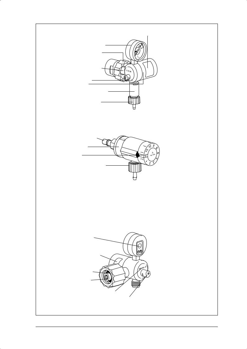
1 Contents gage
2 Connector (oxygen bottle)
3 Rating plate
4 Body
22 Cover |
6 Index head |
Oxygen outlet |
|
(to consumer) |
|
Fixed pressure reducer FIX |
Indexed pressure reducer FAST |
WM 30050; 30100; 30200; |
WM 30600; 30800; 30850 |
30300; 30350 |
|
1 Contents gage
2 Connector (oxygen |
6 Index head |
|
bottle) |
||
|
Oxygen outlet (to consumer)
Multistep pressure reducer Fast II High Flow
WM 31899
8 Flow gage
1 Contents gage
15 Connection nut
2 Connector (oxygen
bottle)
4 Body
22 Cover
Oxygen outlet |
9 Adjuster knob |
(to consumer) |
|
Variable pressure reducer FINE
WM 30500; 30700; 30750
4 Overview
3 Rating plate
1 Contents gage
15 Connection nut
2 Connector (oxygen
bottle)
4 Body
22 Cover
52 Body stage 2
Oxygen outlet (to consumer)
Two-stage pressure reducer OXYTRON WM 30150
2 Connector
22 Cover
6 Index head
Oxygen outlet (to consumer)
Indexed flowmeter
OXYWAY Click WM 31030
13 Service plate
20 Plate for changing filter screw
14 Sealing ring
12 Filter screw
10 Appliance number
11 Safety valve
Rear view of pressure reducer
Overview 5
1.1 Explanation of Numbers
Type: 30800
The type row indicates the basic design of the pressure reducer, e.g. “30800” for indexed pressure reducers (Fast I).
Order number:
In the order number the first three numbers are a short indication of the type, and the last two digits indicate the specific version (e.g. the connection variants).
Appliance number:
The first two digits of the appliance number show the year of manufacture. The next five digits are the consecutive appliance serial number within each type. The appliance number is stamped on the back of the pressure reducer.
1.2 Information about conformity with standards
Up to serial number 0849999, OXYWAY pressure reducers meet standard EN 738-1.
From serial number 0850000, OXYWAY pressure reducers meet standard EN ISO 10524- 1:2006.
In the course of adapting the products to standard EN ISO 10524-1:2006, it was not possible to design all components to be downward-compati- ble. Parts which are not downward-compatible are available for both device statuses separately and are marked accordingly in the replacement parts lists (see “8. Replacement Parts” on page 64) of these instructions.
Caution!
Malfunction as a result of unclear device status.
If replacement parts which are not downward-com- patible are used in the wrong pressure reducers, connected devices will malfunction.
•Fit replacement parts which are not down- ward-compatible only in accordance with the pressure reducer serial numbers quoted.
•Do not convert pressure reducers up to SN 0849999 “to suit the new standard”.
6 Overview
2. Function
2.1 General
During operation, the oxygen coming from the oxygen bottle passes through the bottle valve and the connector 2 into the body 4 of the pressure reducer. You can read off the bottle pressure (delivery pressure) at the contents gage 1.
WEINMANN piston pressure reducers are of modular design. This makes it possible to keep the number of replacement parts to a minimum.
A filter screw with integrated sinter filter (see explanation on right) traps any impurities. A further sinter filter absorbs pressure surges in the oxygen flow.
The filter screw 12 is located at the entrance to the connector 2. The second sinter filter is fitted between the connector 2 and the body 4.
In the reduction stage the bottle pressure is reduced to the required nominal outlet pressure, depending on type. The principle used, with crater drill hole and spring-loaded piston, ensures especially constant pressure in spite of variations in flow.
All pressure reducers are protected against excess pressure by a safety valve 11.
Explanations:
Sinter filter: Small spherical bronze particles are pressed together under heat, creating a filter with a particularly fine pore structure (50 - 75 µm).
Flow: Outlet volume; expressed in liters per minute.
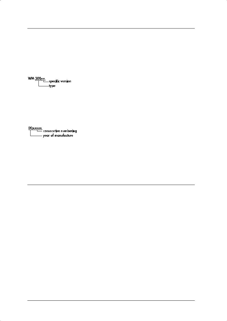
2.2Fixed pressure reducer FIX
(WM 30050; 30100; 30200; 30300; 30350)
A fixed orifice in oxygen outlet 7 creates a constant flow.
The pressure reducers in this series differ in the |
|
|
length and position of the connector 2 and the |
2 |
|
oxygen outlet 7. |
||
|
||
|
7 |
Function 7
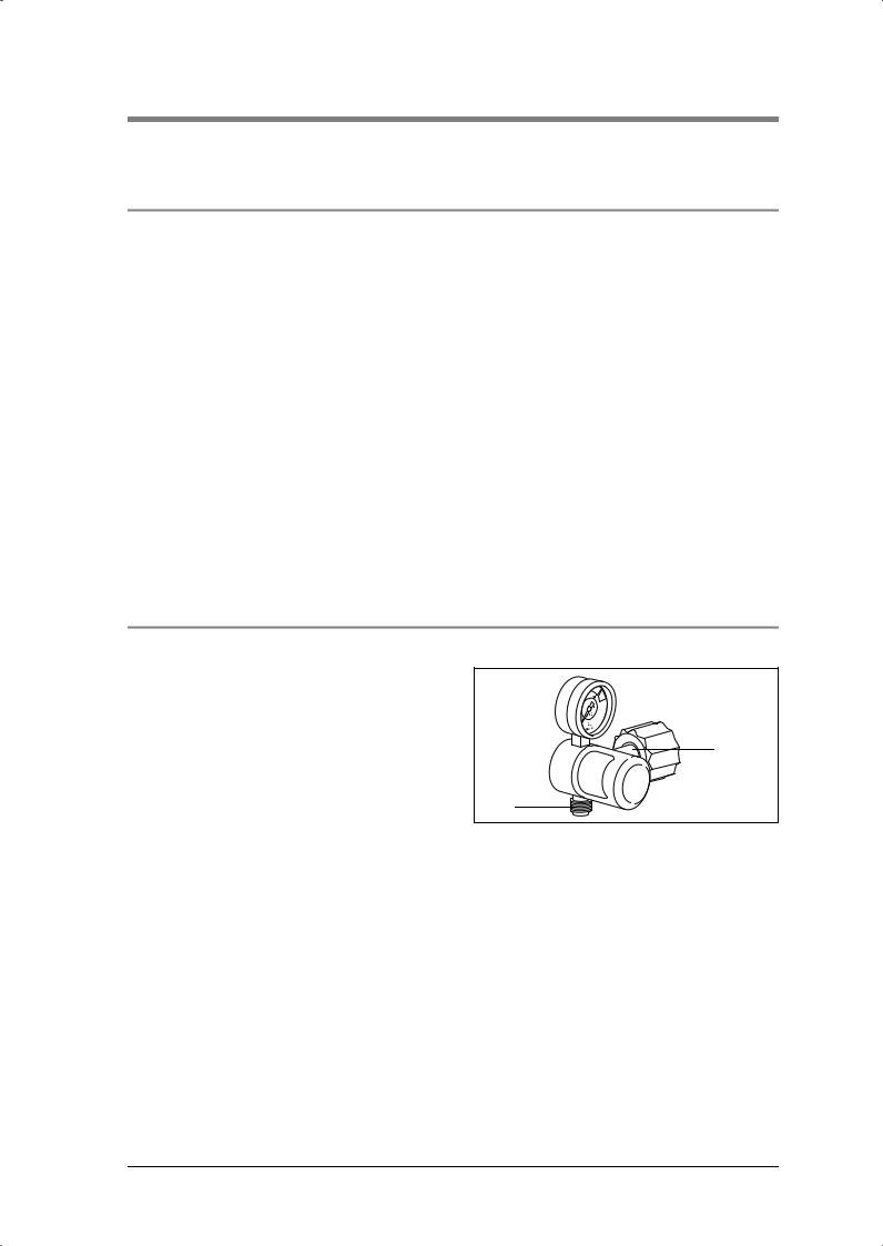
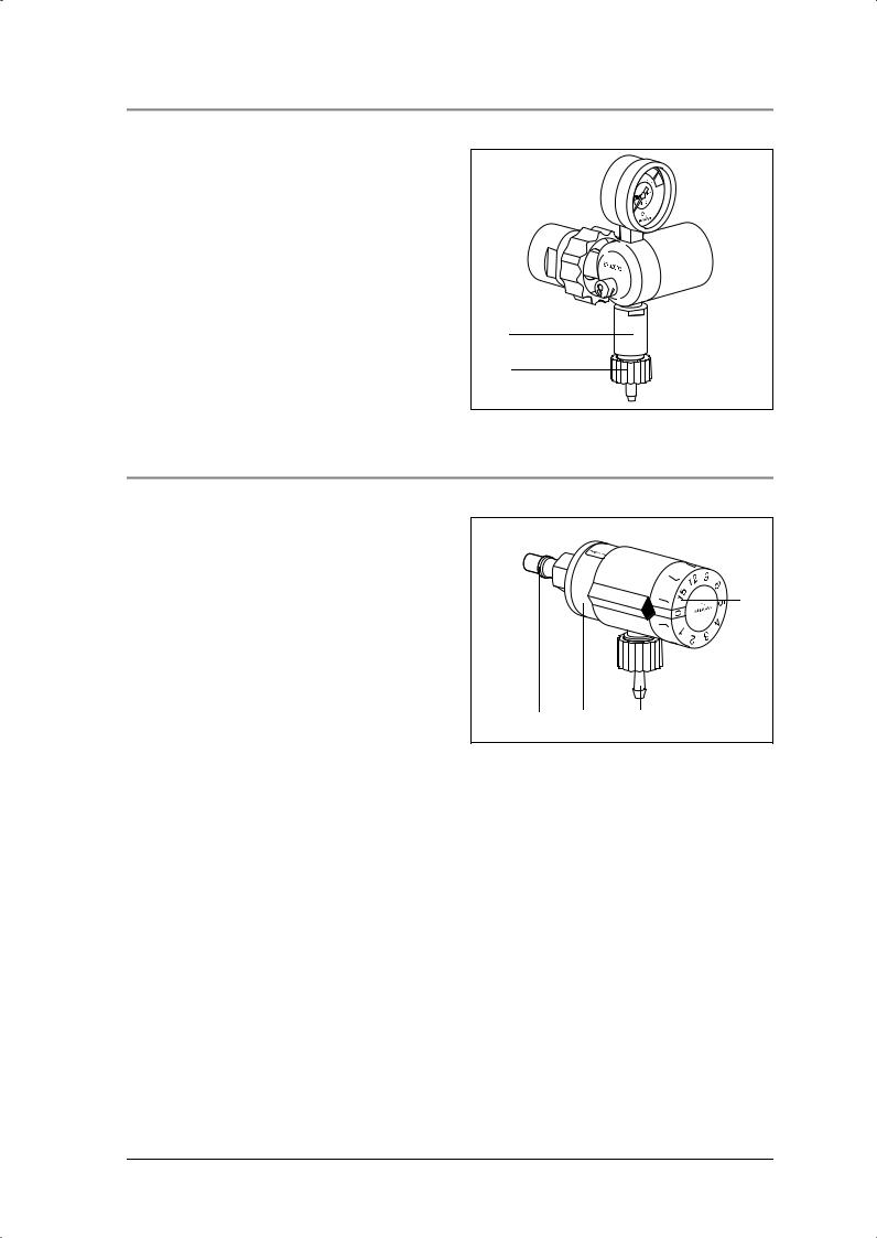
2.3 Variable pressure reducer FINE (WM 30500; 30700; 30750)
The piston is acted upon by a second spring which can be adjusted via a spindle system and thereby creates different outlet pressures. In conjunction with the fixed orifice in the oxygen outlet 7 you can therefore make continuously variable adjustments to the flow. You can read off the flow setting at the flow gage 8.
The pressure reducers in this series differ in the length and position of the connector 2.
2 |
8 |
7 |
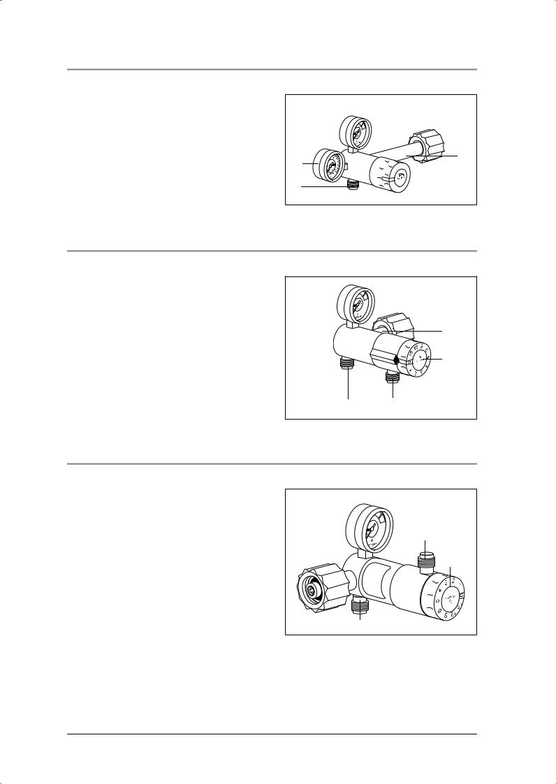
2.4 Indexed pressure reducer FAST (WM 30600; 30800; 30850)
As in the fixed pressure reducers, this creates a |
|
constant operating pressure (outlet pressure). |
|
The index head 6 contains an orifice disc with |
|
various orifice diameters which are aligned by an |
|
index (click-in) system with the oxygen outlet 35. |
2 |
This enables you to set various flow rates. |
|
The pressure reducers in this series differ in the |
6 |
length and position of the connector 2. A pressure |
|
reducer of type WM 30850 has two oxygen |
|
outlets. |
|
7 |
35 |
2.5 Multistep pressure reducer Fast II High Flow (WM 31899)
As in the Fast multistep pressure reducers, there is an orifice disk with a variety of orifice diameters in adjuster 6 which is brought into line with oxygen outlet 35 by means of a locating system.
In addition to the flow outlet, there is a pressure outlet for medical devices with an oxygen requirement in excess of 90 l/min. The pressure outlet and the flow outlet may not be in operation simultaneously.
35 |
6 |
7 |
8 Function
2.6 Two-stage pressure reducer OXYTRON (WM 30150)
The two-stage pressure reducer has a first stage in |
|
the form of a fixed pressure reducer WM 30100, |
|
and a second reduction stage 52 to permit optimal |
|
adjustment of pressure and flow to suit the |
|
OXYTRON oxygen device. |
|
In the second stage the pressure of 4.5 bar from |
|
the first stage is similarly reduced by a system of |
|
crater drill hole and spring-loaded pistion to |
|
1.6 bar. |
|
A fixed orifice in the oxygen outlet 7 generates a |
52 |
constant flow of 12 l/min. |
7 |
|
2.7 Indexed flowmeter OXYWAY Click
During operation, the oxygen supplied by the central gas system at a pressure of 4.5 bar passes through the inlet connector 2 into the body 22 of the OXYWAY Click.
The dial head 6 contains an orifice disk with orific- |
|
6 |
es of different diameters which are lined up with |
|
|
the oxygen outlet 35 by means of a click dial sys- |
|
|
tem. You can set the following flow rates: 1, 2, 3, |
|
|
4, 5, 6, 9, 12, 15 l/min.. |
|
|
2 |
22 |
35 |
Function 9
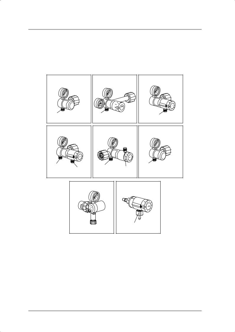
2.8 Oxygen outlets pressure reducer OXYWAY
Oxyway pressure reducers are available with different oxygen outlets: the pressure outlet and the flow outlet are different (see also “10. Technical Data” on page 79).
Flow outlets are intended for the direct supply of the patient, e.g. via nasal cannula, mask or
intermediate humidifier. Flow outlets have a 9/16 UNF thread.
Pressure outlets are intended to supply ventilators such as the Medumat, modules or distributor bars. Pressure outlets have a G 3/8" thread.
Flow outlet |
Flow outlet |
(Fix I, Lateral outlet Fix I) |
(Fine I up to III) |
9/16 UNF thread |
9/16 UNF thread |
Flow outlet (Fast I and III)
9/16 UNF thread
Pressure and flow outlet |
Pressure and flow outlet |
|||
|
(Fast II) |
(Fast II High Flow) |
||
G 3/8" |
9/16 UNF |
G 3/8" |
9/16 UNF |
|
thread |
||||
thread |
||||
thread |
thread |
|||
|
||||
|
|
|||
Pressure outlet (Fix III, Fix III left)
G 3/8" thread
Flow outlet |
Flow outlet |
||||
(Oxytron) |
(Oxyway Click) |
||||
|
|
|
|
|
|
|
|
|
|
|
|
|
|
|
|
|
|
|
|
|
|
|
|
|
|
|
|
|
|
|
|
|
|
|
|

 9/16 UNF thread 18 x 11 thread
10 Function
3. Final Check
3.1 General
Test conditions:
•Ambient temperature: 15 °C
•Ambient pressure: 1013 hPa
•Connection to oxygen supply. For flow tests, a constant pressure* of 100 bar or 200 bar is required.
*100 bar up to SN 0849999
200 bar from SN 0850000
All the tolerances listed in these instructions (see “10. Technical Data” on page 79) relate to these conditions. Note that if different ambient conditions prevail, deviating measuring results may be obtained.
For the check you will need:
•shutoff valve (max. 6 bar) after oxygen outlet
•test pressure gage 0 - 10 bar
•test pressure gage 0 - 2.5 bar
and three flow meters:
•0 - 50 ml/min
•0 - 20 l/min
•0 - 220 l/min.
If the final check reveals faults, the device must not be used until the defect has been rectified. For possible causes of the defect and how to remedy them, see Chapter “5. Troubleshooting” on
page 18.
A complete check of the OXYWAY Fix, Fast and Fine pressure reducer includes:
•Visual inspection for mechanical damage,
•“3.3.1 Testing system for leaks” on page 12,
•“3.3.2 Testing safety valve for leaks” on page 13,
•“3.3.3 Checking “0” position of contents gage” on page 13,
•“3.3.4 Checking “0” position of flow gage on pressure reducer FINE” on page 13
•“3.3.5 Checking for leaks with valve closed on pressure reducer FINE” on page 14,
•“3.3.6 Checking adjustable flow rate on pressure reducer FINE” on page 14,
•“3.3.7 Checking adjustable flow rate on pressure reducer FAST” on page 14.
•“3.3.8 Checking constant flow rate in pressure reducers FIX, FAST and
FAST II high Flow” on page 15
•“3.3.9 Checking static outlet pressure p4 for all pressure reducers” on page 15.
A complete check of the OXYWAY Click flowmeter includes:
•“3.4 Checking the adjustable output (flow) on the OXYWAY Click” on page 15.
We recommend that you always keep in stock:
•Replacement seal set WM 1148,
•Filter screw WM 30905.
3.2 Intervals
After any servicing or repair work
•Perform a final check.
Final Check |
11 |
3.3 Performing check
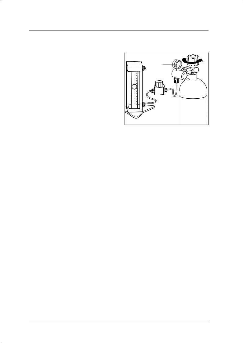
3.3.1 Testing system for leaks
1.Close system after pressure reducer, e.g. by closing a valve after the pressure reducer.
2.Check that all screwed joints and hoses are firmly seated. If necessary tighten joints by hand.
3.Slowly open valve of oxygen bottle. Contents gage 1 of pressure reducer now shows bottle pressure, e.g. 200 bar.
4.To detect leaks, wet screwed connections with a soap-and-water solution. Use Lanosan® med for this purpose.
Warning!
Risk of explosion from soap penetration.
Leaks can cause soap to penetrate the system and combine with the oxygen to form an explosive mixture.
•Open the O2 valve before wetting parts of the system with a soap-and-water solution. The system is then pressurized. No soap can penetrate the system.
•Remove the soap-and-water solution without leaving any residues after the test is complete.
5.Close bottle valve again.
6.Observe needle of contents gage 1 for about 1 minute. If needle stays in same position, the system is gas-tight. If the needle falls steadily, there is a leak.
Eliminating leaks
1 |
We recommend that you keep a stock of replacement seals for the connections.
1.Prepare solution of soapy water, using per- fume-free soap.
2.Wet all screwed joints with solution. If bubbles form, this indicates a leak.
3.Release pressure in system:
–Close oxygen bottle valve.
–Open valve after pressure reducer until contents gage 1 reads “0”.
4.Replace faulty seal responsible for leak (see “6.2 Replacing sealing ring in connector” on page 20).
Important!
Screwed joints of oxygen line must only be hand tightened.
5.Check for leaks again.
6.If leak cannot be eliminated, unit must be repaired.
12 Final Check
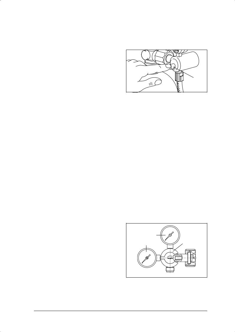
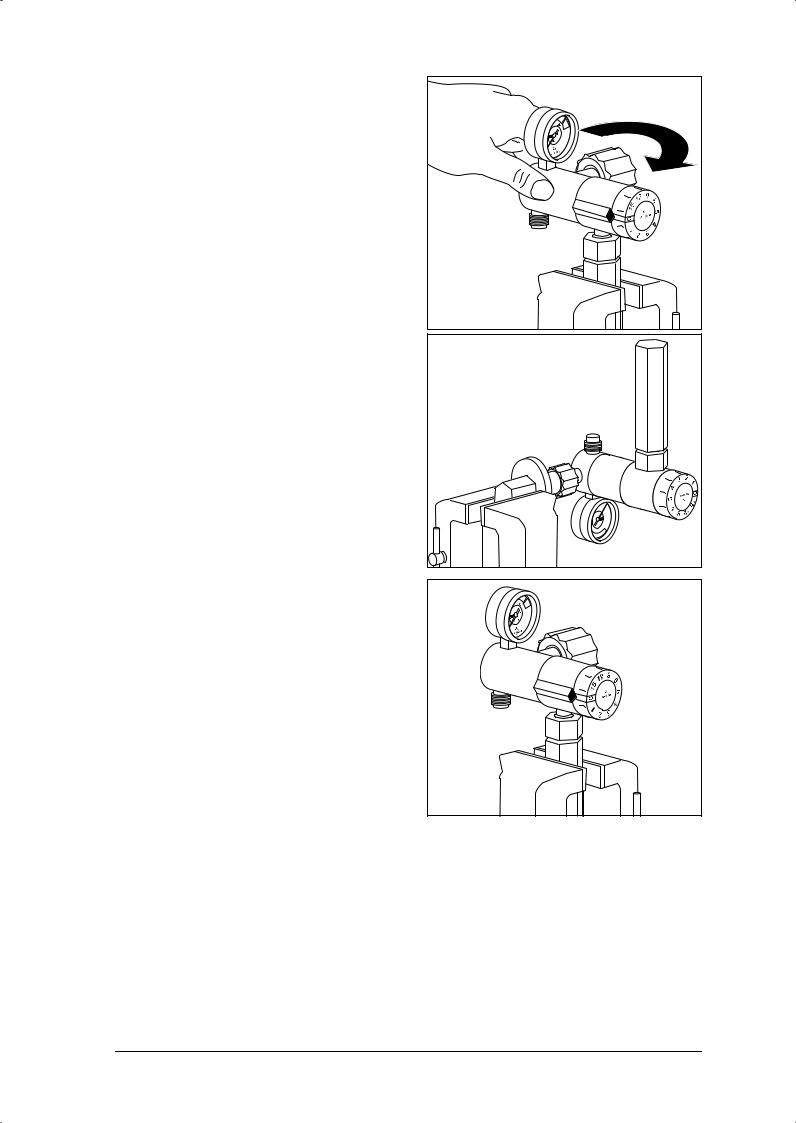
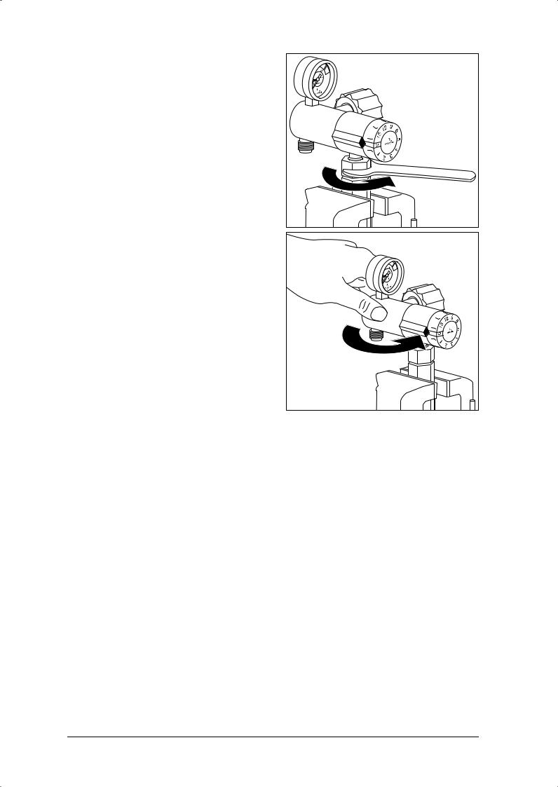
3.3.2 Testing safety valve for leaks
1.Test must be performed at maximum flow. In the Fine and Fast series this is set accordingly.
2.Slowly open oxygen bottle valve.
3. Test with finger whether oxygen is escaping from safety valve 11.
If oxygen is escaping, have pressure reducer repaired by manufacturer (WEINMANN).
Alternatively, you can also wet the safety valve
with soap-and-water solution to find leaks. Use  11 Lanosan® med.
Warning!
Risk of explosion from soap penetration.
Leaks can cause soap to penetrate the system and combine with the oxygen to form an explosive mixture.
•Open the O2 valve before wetting parts of the system with a soap-and-water solution. The system is then pressurized. No soap can penetrate the system.
•Remove the soap-and-water solution without leaving any residues after the test is complete.
3.3.3 Checking “0” position of contents gage
1.Slowly open oxygen bottle valve.
Contents gage 1 now shows bottle pressure.
2.To release pressure in system:
–Close oxygen bottle valve
–Switch on connected appliance
–Open shutoff valve after oxygen outlet.
3.Needle of contents gage 1 now falls toward “0”. Wait until needle stops moving. Now switch appliance off.
4.Check whether needle points exactly to “0”.
If not, fit replacement contents gage (see “6.5 Replacing gage” on page 27).
3.3.4 Checking “0” position of flow gage on pressure reducer FINE
1.Slowly open oxygen bottle valve.
2.Set flow rate (e.g. 7 l/min) at adjuster knob 9. You can read the set value at the flow gage 8.
3.To release pressure in system:
–Close oxygen bottle valve
–Open shutoff valve after oxygen outlet
–Switch on connected appliance.
4.Needle of flow gage 8 now falls toward “0”. Wait until needle stops moving. Now switch appliance off.
5.Check whether needle points exactly to “0”.
If not, fit replacement gage (see “6.5 Replacing gage” on page 27).
1
8 |
9 |
Final Check |
13 |

3.3.5 Checking for leaks with valve closed on pressure reducer FINE
You need a flow meter with a range of 0 – 50 ml/min.
Perform measurement at an inlet pressure of 200 bar.
1.Slowly open oxygen bottle valve.
Contents gage 1 now shows bottle pressure.
2.Check whether flow gage 8 shows a flow rate of “0”.
If not, use adjuster knob 9 to set flow rate to “0”.
3.Connect flow meter (0 - 50 ml/min) to oxygen outlet 7.
4.Wait until flow meter shows constant reading.
5.Read off value.
If value is greater than 30 ml/min, fit replacement piston (see “6.7 Replacing piston in pressure reducer FINE (WM 30500, 30700, 30750)” on page 30).
3.3.6 Checking adjustable flow rate on pressure reducer FINE
You need a flow meter with a range of 0 – 20 l/min.
Perform measurement at an inlet pressure of 100 bar ± 10 bar.
1.Slowly open oxygen bottle valve.
Contents gage 1 now shows bottle pressure.
2.Turn adjuster knob 9 to the left as far as it will go, until flow gage 8 shows a flow rate of “0”.
3.Connect flow meter to oxygen outlet 7.
4.Set any desired flow rate at adjuster knob 9.
5.Check on flow meter whether actual value agrees with set value.
Note tolerances of pressure reducer: 1 to 5 l/min: ± 0.5 liters,
6 to 15 l/min: ± 10 %.
6.If any value does not agree, have pressure reducer repaired by manufacturer (WEINMANN).
Note: Checking the flow of the second oxygen outlet is described in a later section (3.3.8, page 15).
3.3.7 Checking adjustable flow rate on pressure reducer FAST
You need a flow meter with a range of 0 – 20 l/min.
Perform measurement at an inlet pressure of 100 bar ± 10 bar.
1.Slowly open oxygen bottle valve.
Contents gage 1 now shows bottle pressure.
2.Set flow of “0” at index head 6.
3.Connect flow meter to oxygen outlet 7.
4.Set any desired flow rate at index head 6.
5.Check on flow meter whether actual value agrees with set value.
Note tolerances of pressure reducer: 1 to 5 l/min: ± 0.5 liters,
6 to 15 l/min: ± 10 %.
6.If any value does not agree, have pressure reducer repaired by manufacturer (WEINMANN).
Note: Checking the flow of the second oxygen outlet is described in a later section (3.3.8, page 15).
14 Final Check

3.3.8Checking constant flow rate in pressure reducers FIX, FAST and FAST II high Flow
You need a flow meter as follows:
•For WM 30050, 30100, 30150: flow meter 0 – 20 l/min
•For WM 30200, 30300, 30350, 30850, 31899: flow meter 0 – 220 l/min.
1.Connect flow meter to oxygen outlet.
2.Close
–on pressure reducers WM 30850 and WM 31899: oxygen outlet for adjustable flow,
–on pressure reducer WM 30200: second oxygen outlet (on the side).
3.Slowly open oxygen bottle valve.
–Contents gage 1 now shows bottle pressure
–Flow meter shows flow rate.
4.Check flow rate reading against set value.
Pressure reducers must maintain the following flow rates:
WM 30050, 30100: 4 l/min ± 0.5 l/min
WM 30150: |
12 l/min ± 1.2 l/min |
WM (30200), 30300, |
|
30350: |
120 l/min ± 15 l/min |
WM 30850: |
90 l/min ± 10 l/min |
WM 31899: |
min. 160 l/min |
5.In the event of discrepancies, have pressure reducer repaired by manufacturer (WEINMANN).
6.There is a second oxygen outlet on pressure reducer WM 30200. This is a free pressure outlet.
3.3.9 Checking static outlet pressure p4 for all pressure reducers
1.Connect appropriate test gage to oxygen outlet 7.
2.Check closing pressures p4 (see “10. Technical Data” on page 79). They are valid for a
delivery pressure of p1* = 100 bar or
200 bar and must be reached within 1 minute at most. After this they must not show any further increase.
*100 bar up to SN 0849999
200 bar from SN 0850000
3.4Checking the adjustable output (flow) on the OXYWAY Click
You need a flow meter with a range of 0 – 20 l/min.
Perform the measurement at an inlet pressure of 4.5 bar ±0.2 bar.
1.Set the flow "0" at index head 6.
2.Plug the flowmeter into a suitable compressed gas supply (e.g. a central gas supply system).
3.Connect the flow meter to the oxygen outlet.
4.Set any flow value at index head 6.
5.Check on the flow meter whether the set value corresponds to the actual value.
Please observe the tolerances of the flowmeter in the process.
Rising test:
1 to 5 l/min: ±0.5 liter,
6 to 15 l/min: ±10 %.
Falling test:
6 ±10 % and 0/min: ±0.15 l/min
Final Check |
15 |

4. Servicing
4.1 General
We recommend that all maintenance work, such as inspections and repairs, be carried out by the manufacturer (WEINMANN) or by expert technical personnel trained by WEINMANN.
When carrying our repairs, be sure to observe the directions in these Service and Repair Instructions.
4.2Intervals and scope for OXYWAY and OXYTRON pressure reducers
In cases of dirt accumulation, or at least every 2 years:
1.Fit replacement filter screw 12 (see “6.3 Replacing filter screw” on page 21).
2.Perform a functional check (see “6. Functional Check“ on page 12 of the Operating Instructions”).
Every 4 years
1.Fit replacement filter screw 12 (see “6.3 Replacing filter screw” on page 21);
2.Completely replace piston 16.
–For pressure reducers WM 30050, 30100, 30200, 30300 and 30350: see Section 6.6, page 28,
–For pressure reducers WM 30500, 30700, 30300 and 30750:
see Section 6.7, page 30,
–For pressure reducers WM 30600; 30800, 30850:
see Section 6.8, page 33;
–For pressure reducers WM 31899; 30800, 30850:
see Section 6.9, page 36;
3.Fit replacement sinter filter 19 (see “6.12 Replacing Connector and Sinter Filter” on page 50);
4.Fit replacement sealing ring 14 (see “6.2 Replacing sealing ring in connector” on
page 20)
5.Perform a final check (see “3. Final Check” on page 11). If you find any faults, rectify them.
6.Replace service plate 13 with a new one with the new data from “8. Replacement Parts” on page 64.
4.3 Intervals and scope for OXYWAY Click flowmeter
Check metering accuracy by having a check measurement performed every 4 years.
We recommend that repair work be performed only by the manufacturer, WEINMANN, or by trained qualified experts expressly authorized by WEINMANN.
16 Servicing

4.4 Storage
If the pressure reducer is to remain unused for long periods, we recommend the following procedure:
1.Clean pressure reducer (see “Hygienic preparation” in the Operating Instructions).
2.Store pressure reducer in a dry place.
Important:
Be sure to observe the servicing intervals for stored appliances as well. Otherwise the appliance is no longer fit for use on removal from storage.
4.5 Disposal
Do not dispose of the unit with domestic waste. To dispose of the unit properly, please contact a licensed, certified electronic scrap disposal merchant. This address is available from your Environment Officer or from your local authority.
Servicing 17

5. Troubleshooting
5.1 Pressure reducer OXYWAY and OXYTRON
Fault |
Cause |
Remedy |
|
|
|
|
|
|
Damaged sealing ring. |
Replace sealing ring |
|
Leak at connector |
(Section 6.2, page 20). |
||
|
|||
(bottle connection). |
Damaged seat for connector sealing |
Replace connector |
|
|
ring. |
(Section 6.12, page 50). |
|
|
|
|
|
Leak at oxygen outlet |
Damaged sealing ring. |
Replace sealing ring |
|
(appliance connection). |
(Section 6.2, page 20). |
||
|
|||
|
|
|
|
|
Unacceptable pressure rise in |
Replace piston |
|
|
(Section 6.6, page 28 or |
||
|
pressure reducer (delayed rise |
||
|
Section 6.7, page 30 or |
||
Leak at relief valve. |
effect). |
||
Section 6.8, page 33). |
|||
|
|||
|
|
|
|
|
Relief valve not gas-tight. |
Have pressure reducer repaired by |
|
|
Crater in body faulty. |
manufacturer (WEINMANN). |
|
|
|
|
|
Pressure gage does not read |
Pressure gage faulty. |
Replace pressure gage |
|
“0” at zero pressure. |
|
(Section 6.5, page 27). |
|
|
Oxygen outlet faulty. |
Replace oxygen outlet |
|
|
(Section 6.4, page 21) |
||
|
|
||
|
|
|
|
Outlet flow rate too low. |
Index disk faulty. |
Replace index disc (Section 6.9, |
|
page 36) |
|||
|
|
||
|
|
|
|
|
Index disk incorrectly adjusted. |
Replace index disc (Section 6.9, |
|
|
page 36) |
||
|
|
||
|
|
|
|
Outlet flow rate of OXYTRON |
|
|
|
WM 30150 outside |
|
|
|
tolerance of |
|
|
|
12 l/min ± 1.2 l/min |
Second stage faulty |
Replace complete piston |
|
Outlet pressure of OXYTRON |
(Section 6.16, page 56) |
||
|
|||
WM 30150 outside |
|
|
|
tolerance of |
|
|
|
1.5 bar ± 0.08 bar |
|
|
|
|
|
|
|
|
|
Replace piston |
|
Variable pressure reducer: |
|
(Section 6.6, page 28 or |
|
leak at oxygen outlet 7 |
Unacceptable pressure rise in |
Section 6.7, page 30 or |
|
> 30 ml/min |
Section 6.8, page 33) |
||
pressure reducer. |
|||
(with valve closed and |
or |
||
|
|||
200 bar bottle pressure). |
|
have pressure reducer repaired by |
|
|
|
manufacturer (WEINMANN). |
|
|
|
|
18 Troubleshooting

5.2 Flowmeter OXYWAY Click
Fault |
Cause |
Remedy |
|
|
|
|
|
Unusually high oxygen |
Leak in system |
Find and eliminate leak |
|
consumption |
|||
|
|
||
|
|
|
|
Inadequate O2 supply during |
Leak in system |
Find and eliminate leak |
|
|
|
||
Defect or internal soiling in |
|
||
inhalation |
Have flowmeter repaired |
||
flowmeter |
|||
|
|
||
|
|
|
|
Flowmeter not working |
Flowmeter defective |
Have flowmeter repaired |
|
|
|
||
Oxygen source defective or empty |
Check oxygen source |
||
|
|||
|
|
|
Troubleshooting 19
6.Repair Information and Repair Instructions for pressure reducer OXYWAY and OXYTRON
6.1 General
•Observe the safety information on page 4 of the Operating Instructions for OXYWAY.
•Caution: Risk of explosion!
To prevent explosion risks, make sure your hands, tools and workplace are absolutely free from oil and grease during the repair work.
For this reason you should always wash your hands before starting work.
•Any operations on the appliance presuppose detailed knowledge and observance of the Operating Instructions and the Service and Repair Instructions.
•You should only carry out repairs described in these Service and Repair Instructions. Otherwise proper functioning of OXYWAY cannot be guaranteed.
•Be sure to perform a final check after every repair (see “3. Final Check” on page 11).
•If you replace components or individual parts, always use genuine WEINMANN parts only.
•If there is a fault in the body or the relief valve, have OXYWAY repaired by the manufacturer (WEINMANN).
•Certain parts must be screwed up using a torque wrench. To ensure compliance with the specified torque, check your torque wrench regularly for torque compliance (control of inspection, measuring and test equipment).
•Note:
The item numbers in the following text are the same as the item numbers in the Replacement Parts List on page 64 and the overview on page 4.
6.2 Replacing sealing ring in connector
Tools required:
•From tool set WM 15366:
– Watchmaker’s screwdriver WM 3004130041 (cleaned with methylated spirit).
1.Using a cleaned screwdriver, ease sealing ring 14 carefully out of its groove.
Be careful not to damage the groove in any way.
2.If necessary, clean the groove with a dry cloth or a cloth moistened with clean water.
3.Carefully press a new sealing ring into the groove. Do not use any tools for this.
4.Perform a final check (see “3. Final Check” on page 11).
14 |
20 Repair Information and Repair Instructions for pressure reducer OXYWAY and OXYTRON
6.3 Replacing filter screw
Tools required:
•From tool set WM 15366:
– Allen wrench 4 mm WM 30042 (cleaned with methylated spirit).
1.If necessary, clean out the hexagonal socket of the filter screw 12 with a small screwdriver.
2. Loosen the filter screw 12, but do not unscrew it completely yet.
3. So that no dirt can fall into the pressure reducer, hold it with the connector pointing down. In this position, remove the filter screw 12.
4. Screw a new filter screw 12 into the connector |
|
stub and tighten. |
12 |
5. Perform a final check. Enter the change of filter screw with date in the service record.
6.4 Replacing oxygen outlet
6.4.1 Replacing G 3/8 pressure outlet
Tools and material required:
•From tool set WM 15366:
–Counter tool with clamping handle WM 30035,
–Screwdriver bit 9 mm WM 30039 (cleaned with methylated spirit);
–Watchmaker’s screwdriver WM 30041 (cleaned with methylated spirit);
•Vise;
•Sealing ring 14 (WM 1145);
•Loctite 245 WM 14920 (never use other Loctite products).
•Torque wrench 25 Nm ± 1 Nm,
Note:
The oxygen outlet must always be replaced as a complete unit, because the flow rate cannot be guaranteed if individual parts are replaced.
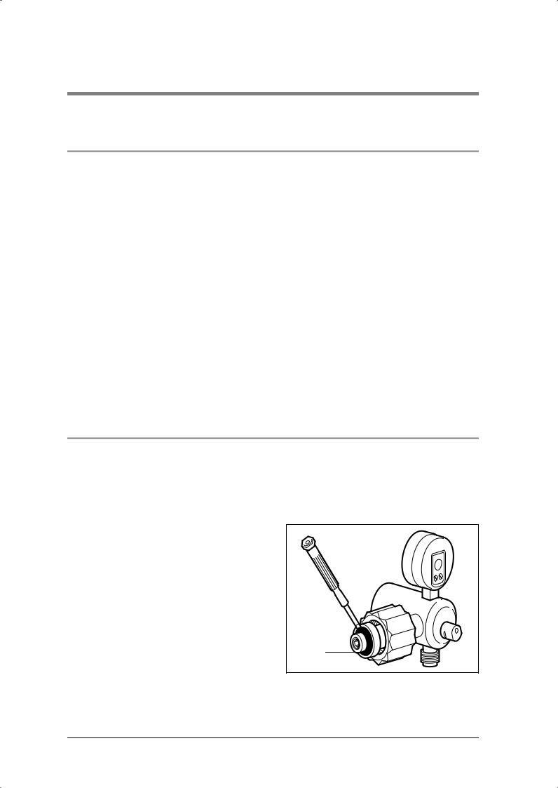
1. Clamp pressure reducer firmly in counter tool. |
|
|
To do this, perform the following steps: |
|
|
– Using a cleaned screwdriver, carefully ease |
7 |
|
|
sealing ring 14 out of groove in connector. |
|
|
Be careful not to damage the groove at all. |
2 |
– |
Clamp bottom part of counter tool firmly in |
|
|
a vise. |
|
– Place the top part of the counter tool on the |
|
|
|
bottom part of the counter tool. |
|
– |
Screw the connection nut onto the bottom |
|
|
part of the counter tool. |
|
– Tighten the connection nut using the top part |
|
|
|
of the counter tool. |
|
Repair Information and Repair Instructions for pressure reducer OXYWAY and OXYTRON 21
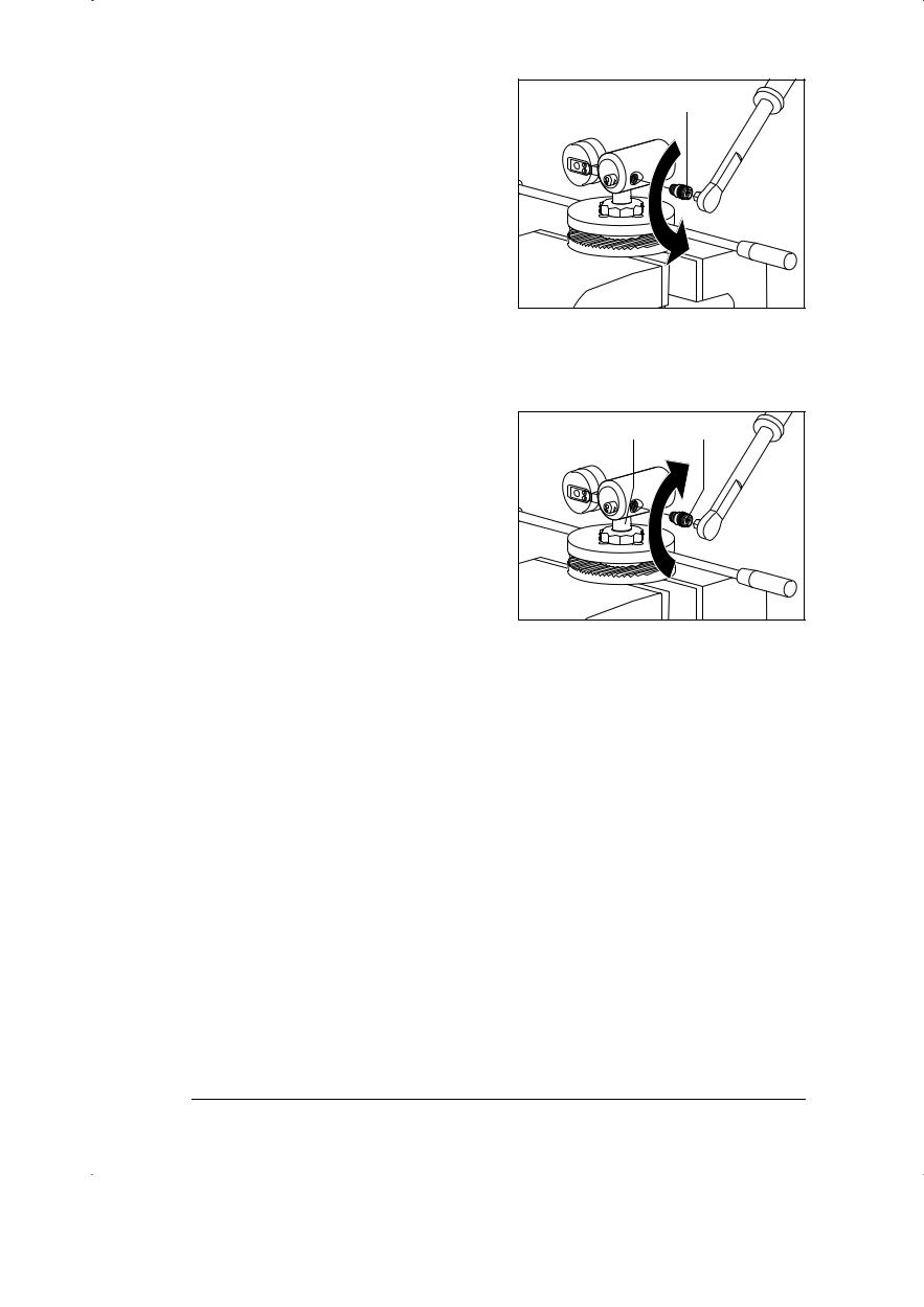
2.Using cleaned screwdriver bit, unscrew defective oxygen outlet 7 by turning to left.
3.Fit new oxygen outlet 7:
–Remove any adhesive residues from screw threads. Use a brass wire brush for the external thread and if necessary a tap G 1/ 8 for the internal thread.
Caution:
When cleaning threads, no dirt must enter body of pressure reducer.
–Take a new oxygen outlet .
Caution:
The oxygen outlet must be clean and free from oil and grease.
–Apply a little Loctite 245 to screw thread with the exception of the first two turns.
The first two turns must be kept free of Loctite to ensure that no Loctite enters the body of the pressure reducer.
–Screw oxygen outlet 7 by hand into pressure reducer.
–Tighten oxygen outlet 7 with 9 mm screwdriver bit and a torque wrench
(25 Nm ± 1 Nm).
4.Release pressure reducer from counter tool.
5.If necessary, clean groove in connector 2 with dry cloth or cloth moistened with clean water.
7 |
2 |
7 |
6.Now press new sealing ring 14 carefully into groove. Do not use any tools.
7.Perform a final check
(see “3. Final Check” on page 11).
6.4.2 Replacing UNF 9/16 flow outlet
Tools required:
•UNF 9/16 counter tool, consisting of:
–counter tool WM 14224
–locknut WM 14223
•special wrench SW 20/22, WM 22391
•counter tool WM 30035 (clamping handle not required)
•torque wrench with SW 22 open-end wrench insert.
Remove defective flow outlet
1.Screw locknut WM 14223 onto counter tool WM 14224.
22 Repair Information and Repair Instructions for pressure reducer OXYWAY and OXYTRON
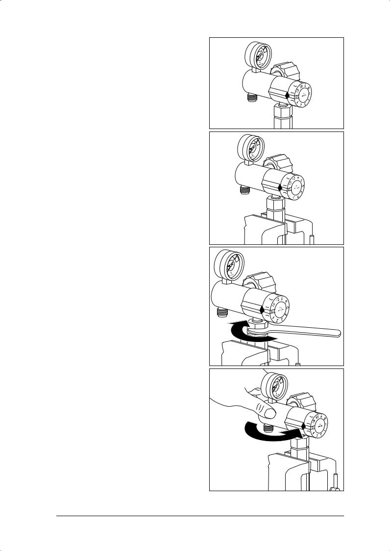
2.Screw the UNF counter tool completely onto the flow outlet of the pressure reducer.
3.Clamp the pressure reducer in a vise so that only counter tool WM 14224 is actually in the vise.
4.To clamp the defective flow outlet firmly in the counter tool, turn locknut WM 14223 clockwise with a 22 mm open-end wrench.
5.To release the pressure reducer from the flow outlet, turn the pressure reducer anticlockwise by hand.
Repair Information and Repair Instructions for pressure reducer OXYWAY and OXYTRON 23
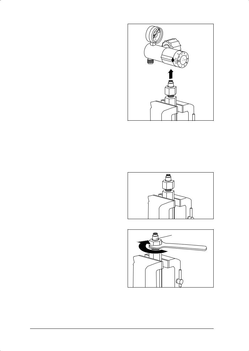
6. Take the pressure reducer off the flow outlet.
7. To release the defective flow outlet in the counter tool, turn locknut WM 14223 anticlockwise with the 22 mm open-end wrench.
8. Unscrew the defective flow outlet from the locknut.
Assembling new flow outlet
Caution:
When cleaning threads, no dirt must enter body of pressure reducer.
1.Take a new oxygen outlet.
Caution:
The oxygen outlet 35 must be clean and free from oil and grease.
2.Screw the new flow outlet fully into the counter
tool.
3. Wet about 2 threads of the new flow outlet with Loctite 245 (WM 14920).
The first two turns must be kept free of Loctite to ensure that no Loctite enters the body of the pressure reducer.
4. Clamp the counter tool in a vise so that only counter tool WM 14224 is actually in the vise.
5. To clamp the new flow outlet firmly in the |
35 |
counter tool, turn the counter tool clockwise |
|
with the 22 mm open-end wrench. |
|
24 Repair Information and Repair Instructions for pressure reducer OXYWAY and OXYTRON
6.Screw the pressure reducer onto the new flow outlet hand-tight.
7.Take the pressure reducer with the counter tool screwed onto it out of the vise.
8.Clamp counter tool WM 30035 in the vise.
9.Screw the pressure reducer and oxygen inlet hand-tight to clamped counter tool WM 30035.
10.Put a torque wrench with open-end wrench insert SW 22 on counter tool WM 14224.
11.Tighten counter tool WM 14224 and thus the new flow outlet on the pressure reducer (torque: 25 Nm ±1 Nm).
12.Release the pressure reducer from counter tool WM 30035.
13.Take counter tool WM 30035 out of the vise.
14.Clamp the pressure reducer in the vise so that only counter tool WM 14224 is actually in the vise.
Repair Information and Repair Instructions for pressure reducer OXYWAY and OXYTRON 25
15.To release locknut WM 14223 from the flow outlet, turn it anticlockwise with the 22 mm open-end wrench.
16.Unscrew the pressure reducer and flow outlet from locknut WM 14223.
17.Take the counter tool out of the vise.
18.Perform a final check
(see “3. Final Check” on page 11).
26 Repair Information and Repair Instructions for pressure reducer OXYWAY and OXYTRON
 Loading...