


 Loading...
MEDUMAT Standard a
Ventilator
Description and instructions for use

Contents
1. Overview . . . . . . . . . . . . . . . . . . . . 4
1.1 Device . . . . . . . . . . . . . . . . . . . . . . 4 1.2 Symbols used on the ventilator. . . . 7
2. Description of ventilator . . . . . . 10
2.1 Uses . . . . . . . . . . . . . . . . . . . . . . . 10
2.2Owner/operator and user
qualification . . . . . . . . . . . . . . . . . 11 2.3 Ventilation function . . . . . . . . . . . 11 2.4 Controlled ventilation. . . . . . . . . . 13 2.5 Assisted ventilation. . . . . . . . . . . . 13 2.6 Check ventilation curve . . . . . . . . 14 2.7 Patient valve. . . . . . . . . . . . . . . . . 14 2.8 Modules. . . . . . . . . . . . . . . . . . . . 15
3. Safety instructions . . . . . . . . . . . 16
3.1 Safety regulations. . . . . . . . . . . . . 16
4. Installation . . . . . . . . . . . . . . . . . . 20
4.1Wall mounting for STATION
MEDUMAT. . . . . . . . . . . . . . . . . . 20
4.2Installation kit for the wall
mounting . . . . . . . . . . . . . . . . . . . 21
4.3Connecting up the oxygen
cylinder . . . . . . . . . . . . . . . . . . . . 21 4.4 Ventilation hose . . . . . . . . . . . . . . 22
5. Using the ventilator . . . . . . . . . . 25
5.1 Switching on/self test . . . . . . . . . . 25 5.2 Selecting the ventilation settings. . 26 5.3 Select ventilation method . . . . . . . 28 5.4 Performing ventilation . . . . . . . . . 30 5.5 Monitoring ventilation . . . . . . . . . 30 5.6 Ventilation with PEEP Valve . . . . . 31 5.7 Ventilation with HME filter . . . . . . 32 5.8 Ventilating with bacteria filter. . . . 32 5.9 Terminating ventilation. . . . . . . . . 33 5.10 Alarm signals . . . . . . . . . . . . . . . . 33
5.11 Calculation of oxygen content/ remaining operating time . . . . . . . 37
5.12 Alternative ventilation
procedures . . . . . . . . . . . . . . . . . . 38
6. Hygienic preparation . . . . . . . . . 39
6.1 MEDUMAT Standard a. . . . . . . . . 39 6.2 Patient valve . . . . . . . . . . . . . . . . 40 6.3 Hose system . . . . . . . . . . . . . . . . 41 6.4 Components and accessories . . . . 42 6.5 Fittings . . . . . . . . . . . . . . . . . . . . 43
6.6Cleaning, disinfecting and
sterilizing . . . . . . . . . . . . . . . . . . . 44
7. Functional checks . . . . . . . . . . . . 45
7.1Preparation for functional check . 45
7.2 Obligatory checks . . . . . . . . . . . . 46 7.3 Check for leaks in the system. . . . 47 7.4 Check of patient valve . . . . . . . . . 48 7.5 Checking the minute volume . . . . 49
7.6Check of maximal ventilation
pressure. . . . . . . . . . . . . . . . . . . . 51 7.7 Check assisted ventilation . . . . . . 52 7.8 Check of alarm systems . . . . . . . . 54
8. Troubleshooting . . . . . . . . . . . . . 57
8.1 Batteries . . . . . . . . . . . . . . . . . . . 59 8.2 Cut-out system . . . . . . . . . . . . . . 60 8.3 Adjustment of manometer. . . . . . 61
8.4Change valve membrane in
patient valve . . . . . . . . . . . . . . . . 61
9. Servicing . . . . . . . . . . . . . . . . . . . . 63
9.1 Intervals. . . . . . . . . . . . . . . . . . . . 63 9.2 Sending in device. . . . . . . . . . . . . 64 9.3 Storage . . . . . . . . . . . . . . . . . . . . 64 9.4 Disposal. . . . . . . . . . . . . . . . . . . . 65
10. Supply schedule . . . . . . . . . . . . . . 66
10.1 Standard supply schedule . . . . . . 66 10.2 Accessories . . . . . . . . . . . . . . . . . 66 10.3 Spare parts . . . . . . . . . . . . . . . . . 67
11. Technical data . . . . . . . . . . . . . . . 68
11.1 Device . . . . . . . . . . . . . . . . . . . . . 68 11.2 Patient’s hose system. . . . . . . . . . 70 11.3 Pneumatics . . . . . . . . . . . . . . . . . 71 11.4 Resistance to interference . . . . . . 72 11.5 O2 content when using Air Mix . . 72
2 EN Contents

11.6 |
Switching from Air Mix to |
|
|
No Air Mix . . . . . . . . . . . . . . . . . . |
73 |
12. |
Warranty . . . . . . . . . . . . . . . . . . . . |
74 |
13. |
Declaration of conformity . . . . . |
74 |
Contents EN |
3 |
1. Overview
1.1 Device
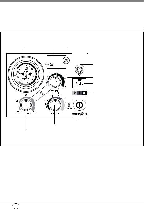
Control panel MEDUMAT Standard a
1 Ventilation pressure gauge 2 Alarm panel 3 Alarm acknowledgement
 Stenosis
 Disconnection
 < 2,7 bar O2
 No assist
MEDUMAT |
|
Standard a |
|
Air Mix |
4 Air Mix/No Air Mix switch |
|
|
No Air Mix |
5 Minute volume regulator |
|
|
|
6 On/Off switch, |
|
assisted ventilation |
|
7 Colour code |
|
Toddler (yellow, 10 kg to 30 kg) |
|
Child (orange, 30 kg to 60 kg) |
|
Adult (brown, 60 kg to 110 kg) |
8 ON/OFF switch
9 Ventilation frequency regulator
10Max. ventilation pressure regulator
4 EN Overview
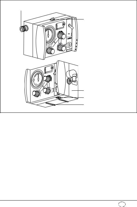
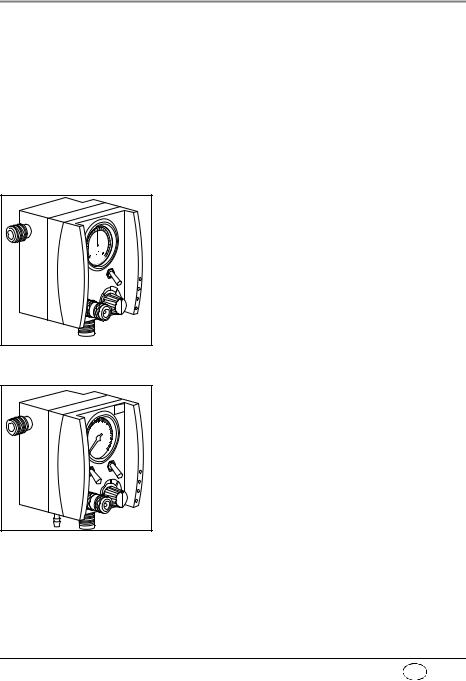
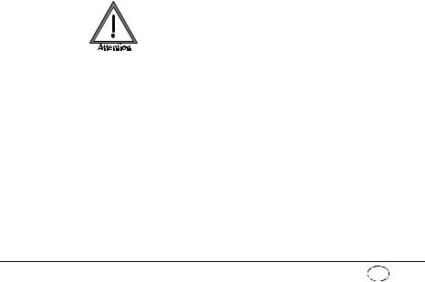
MEDUMAT Standard a connections
11 Pressure gas connection
12 Catch for STATION MEDUMAT wall mounting
 I
I

 13 Connection for ventilation tube

 14 Pressure gauge hose connection
 15 Relief valve
16 Dust cover
17 Mixed air filter
 12 Catch for STATION MEDUMAT wall mounting
Overview EN |
5 |
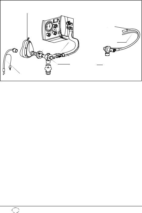
MEDUMAT Standard a device combinations
18 Ventilation mask
Disposable hose system
 19 Ventilation hose
or

 20 Pressure gauge hose 21 Filter
22 Hose casing
23 Patient valve
 24 PEEP valve
25 Tube
6 EN Overview
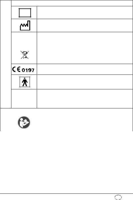
1.2 Symbols used on the ventilator
Position |
> PSU< 134° |
Patient valve
The symbol  on the patient valve indicates that the lip and valve membranes in the expiration and spontaneous breathing arms must be changed immediately if they are crinkled, sticky or misshapen. Under no circumstances continue to use the patient valve for ventilation in this case, as malfunctions are likely (note “7.4 Check of patient valve“ on
page 48).
The symbol  indicates the correct position for insertion of the lip membrane.
When connecting the patient valve, take care to ensure that the direction of respiratory gas flow is correct.
Overview EN |
7 |

MEDUMAT Standard a
|
1 |
|
|
|
|
|
|
|
2 |
|
|
|
|
3 |
|
|
|
|
I |
|
7 |
6 |
5 |
4 |
1 |
Inlet 2,7 - 6 bar O2. |
|
|
|
2 |
Tube system connection |
|
|
|
3 |
Maximum pressure ≤100mbar |
|
|
|
|
Safety check and servicing label |
|
|
|
|
Safety check label: (in Germany only) marks when the next safety |
|||
4 |
check as per §6 of the German law relating to users of medical |
|||
|
devices is required. |
|
|
|
5 |
Servicing label: indicates when the next service is due. |
|||
8 EN Overview
MEDUMAT Standard a device information plate
SN |
Serial number of device |
|
Date of manufacture |
|
|
|
|
|
|
|
|
|
|
Direct voltage |
|
|
|
|
|
|
|
|
|
|
|
|
|
|
|
|
|
|
|
|
|
|
6 |
|
|
|
|
|
|
|
|
|
3,6 V lithium battery |
|
|
|
|
|
|
|
|
|
||
|
|
|
|
|
|
|
|
|
|
|
|
|
|
|
|
|
|
|
|
Do not dispose of device in domestic waste |
|
|
|
|
|
|
|
|
|
|
||
|
|
|
|
|
|
|
|
|
||
|
|
|
|
|
|
|
|
|
|
|
|
|
|
|
|
|
|
|
|
|
|
|
|
|
|
|
|
|
|
|
|
|
CE symbol (confirms that the product conforms to the applicable
European directives)
Type BF application part
Degree of protection
– against the ingress of solid particles IP24 – against access to hazardous parts
– against the ingress of water with a harmful effect
Other markings
7 |
|
Follow instructions for use |
|
|
|
Overview EN |
9 |

2. Description of ventilator
2.1 Uses
The MEDUMAT Standard a is an automatic (shortterm) ventilator with the option of assisted ventilation.
You can use MEDUMAT Standard a:
•to revive patients at the site of the emergency
•on a longer term basis in more protracted emergencies, e.g. fires.
You can use MEDUMAT Standard a while transporting patients:
•between the various rooms and departments of a hospital;
•between the hospital and other premises;
•in emergencies;
•when transport over a considerable distance is planned.
MEDUMAT Standard a:
•is designed to provide controlled ventilation to persons of approx. 10 kg body weight or more, or in the case of assisted ventilation, of approx. 15 kg body weight or more.
•is used to treat respiratory arrest;
•can be preset to parameters that ensure evenly balanced ventilation provided that the selected maximum ventilation pressure Pmax is not exceeded.
•can be supplied with additional modules for aspiration and oxygen inhalation. (N.B.
10 |
EN Description of ventilator |
MEDUMAT Standard a cannot be used as a ventilator simultaneously with these modules.)
2.2 Owner/operator and user qualification
As an owner/operator or user, you must be familiar with the operation of this medical device. Observe the legal requirements for operation and use (in Germany, the regulations governing owner/operators of medical devices apply in particular). Basic recommendation: get a person authorized by Weinmann to provide you with proper instruction about the handling, use and operation of this medical device.
2.3 Ventilation function
MEDUMAT Standard a operates within a pressure range of 2.7 to 6 bar and at a flow rate of not less than 70 l/min O2. It has an in-built power pack.
It uses high-pressure, medicinal-grade oxygen. An external pressure reducer brings this down to the required operating pressure. The oxygen supply is fed in at input valve.
Both the infinitely variable ventilation frequency and the inspiration/expiration ratio of 1:1.67 in the case of controlled ventilation are regulated by internal electronic control mechanisms.
The gas for inspiration is routed to the patient through the ventilation tube via the patient valve and the ventilation mask or hose. A lip membrane
Description of ventilator EN |
11 |
Air Mix
No Air Mix
in the patient valve ensures that the expiration gas can be exhaled through the expiration arm.
Regardless of the ventilation mode selected, the patient has the option of breathing spontaneously between ventilation strokes via the patient valve. In this case, the patient draws air for breathing from the ambient air.
With the Air Mix setting, in the case of mechanical ventilation, atmospheric air is admixed to give an O2 concentration generally of between 55 % and 85 % at 10 mbar ventilation pressure (note “11.5 O2 content when using Air Mix“ on page 72).
Air Mix
No Air Mix
In certain indications and in cases where the surrounding atmosphere is contaminated, you can switch to No Air Mix and ventilate with pure oxygen.
The injector unit is switched off when switching from Air Mix to No Air Mix. This increases minute volume which can result in the set pressure limit being exceeded and a stenosis alarm (Stenosis) being triggered. In this case, set minute volume correspondingly lower.
In the opposite instance, in other words when switching from No Air Mix to Air Mix, the injector unit is switched on. This reduces minute volume which can lead to the set pressure limit being undershot. In this case, set minute volume correspondingly higher.
12 |
EN Description of ventilator |
2.4 Controlled ventilation
Mandatory ventilation stroke: the device, not the patient, determines the time of the next breathing stroke.
After being switched on, the MEDUMAT Standard a is automatically in Controlled Ventilation mode. This administers mandatory ventilation strokes to the intubated patient according to the ventilation values set on the device.
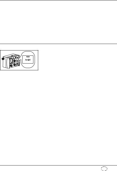
2.5 Assisted ventilation
Triggered ventilation stroke: the patient can trigger a ventilation stroke by his own breathing efforts.
IPPV: intermittent positive pressure ventilation (= controlled ventilation).
In addition to Controlled Ventilation mode, the MEDUMAT Standard a also has an Assisted Ventilation mode.
After you have switched on Assisted Ventilation mode by pressing the Assist key, a flashing green LED indicates this mode.
The patient now has the option of triggering a triggered ventilation stroke within a time window of 40 % of expiration. To do so, the patient must generate a flow of over 6 l/min. by his own breathing efforts.
If the breathing efforts of the patient are not sufficient to trigger, the patient automatically receives a mandatory ventilation stroke at the end of the time window, so that the set minute volume is guaranteed.
With this function, the ventilation strokes of the device can be synchronised with the breathing efforts of the patient.
Between the mandatory ventilation strokes of the device, the patient has the option of breathing in air from the surrounding atmosphere via the patient valve.
Description of ventilator EN |
13 |
If the patient does not trigger the device, an alarm is triggered. The patient continues to receive controlled ventilation.
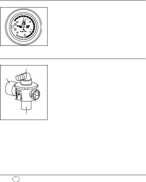
2.6 Check ventilation curve
The ventilation curve is checked at ventilation pressure gauge.
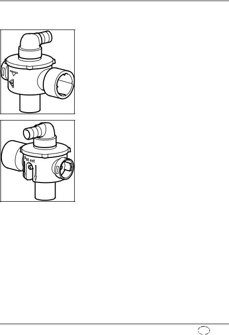
2.7 Patient valve
Respiration hose connection
Expiration tube
Connection |
Sponta- |
|
for pressure |
||
neous |
||
gauge tube |
||
breath- |
||
|
||
Mask/tube connectioning tube |
||
The gas for inspiration is channelled into the patient’s airways through the patient valve.
It is designed so that spontaneous breathing is possible, even if the MEDUMAT Standard a fails, regardless of which ventilation mode you have selected.
14 |
EN Description of ventilator |
2.8 Modules
UL |
|
MOD |
en |
Oxyg |
|
MODUL |
Combi |
10 |
5 |
O2 |
Modules with additional functions can be attached to MEDUMAT Standard a.
Please refer to the directions for use enclosed with the modules for exact details of how to fit and operate these. It is essential to read these directions carefully before using the modules. The most important points are listed below:
Oxygen MODULE
The Oxygen MODULE enables you to apply oxygen inhalation.
Put the switch marked O2 into the “I“ position. Select the desired oxygen volume by turning the knob marked l/min to a setting between 0 and 15 l/min. You can check this setting on the volume manometer.
Combi MODULE
The Combi MODULE enables you to apply both oxygen inhalation and suction.
For inhalation put the switch marked O2 into the “I“ position. Select the desired oxygen volume by turning the knob marked l/min to a setting between 0 and 15 l/min. You can check this setting on the volume manometer.
For suction switch the tumbler marked Vac to the “I“ position. The suction pressure is locked at -0.5 bar.
Description of ventilator EN |
15 |

3. Safety instructions
3.1 Safety regulations
For your own safety, the safety of your patients, and to comply with the requirements of EU Directive 93/ 42/EEC, please observe the following points:
General
•Please read the directions for use carefully. They are an integral part of the ventilator and should be available for reference at all times.
•Before starting to work with
MEDUMAT Standard a, you must understand how to operate it.
•Please comply with section “6. Hygienic preparation“ on page 39 to prevent infection or bacterial contamination.
•MEDUMAT Standard a should be used only by medically qualified personnel who have had training in ventilation techniques. Incorrect use can cause severe physical injury.
•It is advisable for you to have servicing and repairs carried out only by the manufacturer, Weinmann, or by qualified technicians expressly authorized by Weinmann.
•If third-party items are used, functional failures may occur and fitness for use may be restricted. Biocompatibility requirements may also not be met. Please note that in such cases, any claim under warranty and liability will be voided if neither the accessories nor genuine replacement
16 |
EN Safety instructions |
parts recommended in the instructions for use are used.
•MEDUMAT Standard a should be used only for the purposes for which it is designed (note “2.1 Uses“ on page 10).
•MEDUMAT Standard a is not designed for use under hyperbaric conditions (pressure chamber).
•MEDUMAT Standard a should never be used with flammable anaesthetics.
•In the case of use in poisoned or low-oxygen atmospheres, do not operate the MEDUMAT Standard a with the „Air Mix“ setting or in Assist mode.
•A back-up ventilator should always be available in case of technical failure.
Warning: • Modifications may not be made to the device. Have modifications to the device carried out only by the manufacturer, Weinmann, or by specialist staff expressly authorized by the manufacturer.
Oxygen
Highly-compressed oxygen can lead to spontaneous explosive reactions in combination with flammable substances (fat, oil, alcohol, disinfectants, etc.):
•All screw connections and other components of the ventilator must be kept absolutely free of oil and grease.
•Always wash your hands before starting to work on the oxygen supply.
•Smoking and open flames are strictly prohibited in the vicinity of all fittings containing or transporting oxygen.
•During assembly and when changing the oxygen cylinder, only hand pressure should be used
Safety instructions EN |
17 |
when tightening the screw connections to the cylinder and to the pressure reducer. Never use tools for this purpose. Excessive tightening damages the screw threads and seals and can cause leaks.
•Protect oxygen cylinders from accidental falls. If a cylinder falls, the pressure reducer or the valve may break off and cause a violent explosion.
Important note • Always open the valve of the oxygen cylinder slowly to prevent pressure damage to the other fittings.
•The oxygen cylinder should never be completely emptied as this may allow moisture-containing air to enter the cylinder and cause corrosion.
Operation
•Both the patient and the ventilator must be kept under constant observation during ventilation.
• Make sure that neither the expiration tube nor the spontaneous breathing tube on the patient valve is blocked or impeded in any other way, e.g. by the patient’s position.
•MEDUMAT Standard a must never be used simultaneously with a module as this would make it impossible to work to the selected parameters.
Note • Disposable hose systems WM 28110 (2 m) and WM 28188 (3 m) are only intended to be used once.
Software
•Extensive validation tests have been performed to minimize risks arising from software errors.
18 |
EN Safety instructions |

Accessories
•Please protect the silicone and rubber components against UV radiation and prolonged exposure to direct sunlight, as this can make them brittle and friable.
Safety instructions EN |
19 |
4. Installation
A permanent mounting is usually necessary only when MEDUMAT Standard a is installed as a fixture in rescue vehicles, helicopters or aircraft. In these cases either the STATION MEDUMAT or installation kits are available as accessories.
If MEDUMAT Standard a is supplied complete with carrying platform, it is ready for use and requires no further installation. Separate directions for use are supplied with the carrying platform.
Functional tests must be carried out after installation (note “7. Functional checks“ on page 45).
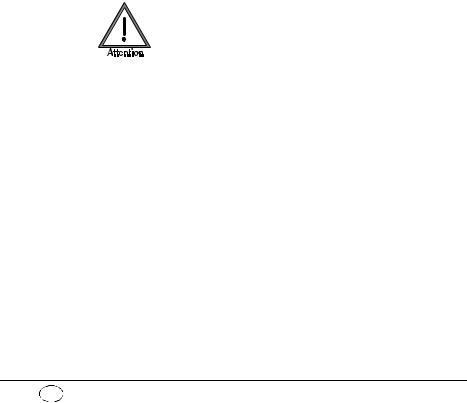
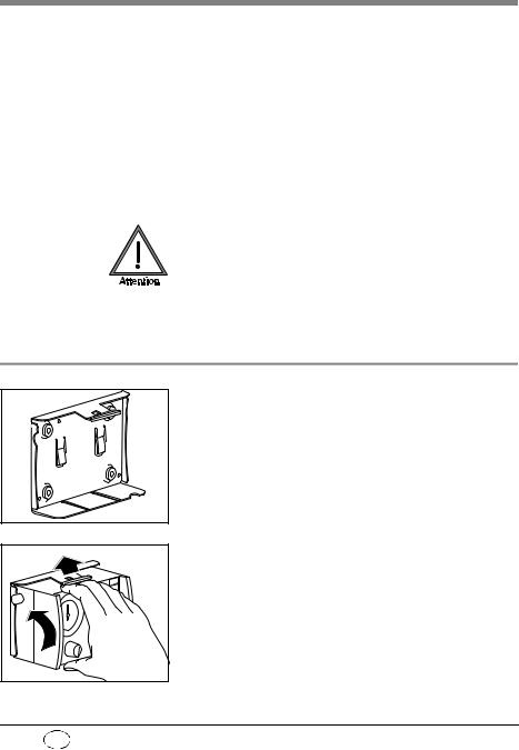
4.1 Wall mounting for STATION MEDUMAT
The wall mounting for the STATION MEDUMAT should be installed at an appropriate place, e.g., on a side panel inside the vehicle. Please refer to the sheet enclosed with the STATION MEDUMAT for details of dimensions and the installation procedure.
To place MEDUMAT Standard a in the wall mounting, first insert the slides on the underside of the ventilator into the matching grooves in the STATION MEDUMAT and then press the MEDUMAT Standard a inwards until the catch snaps into the fastening at the top of the STATION MEDUMAT.
20 EN Installation
4.2 Installation kit for the wall mounting
A number of kits are available for installing a wall mounting, e.g. on a panel inside a vehicle. The kit size varies according to the number of modules attached to the MEDUMAT Standard a.
Please refer to the sheet enclosed with each installation kit for details of dimensions and installation procedure.
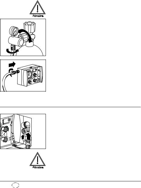
4.3 Connecting up the oxygen cylinder
Wash your hands thoroughly before any work on the oxygen supply. Hydrocarbon compounds (e.g. oils, greases, alcohol for cleaning, disinfectants, hand cream or sticking plaster) can lead to explosive reactions if they come into contact with highly-com- pressed oxygen.
Never use wrenches or similar tools to tighten or loosen the screw connections.
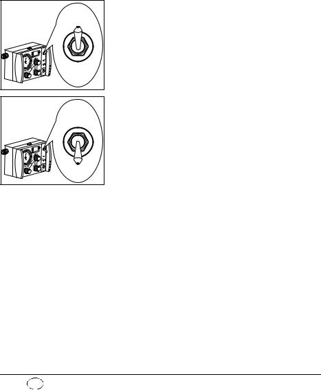
Removal of empty cylinder
1. Close the valve of the oxygen cylinder.
Switch on MEDUMAT Standard a with ON/OFF switch. This exhausts any residual oxygen and depressurizes the ventilator. Wait until the pressure gauge on the pressure reducer shows 0 bar oxygen content before uncoupling the screw connection by hand.
2. First switch off MEDUMAT Standard a again.
3. Then loosen the screw connection to the cylinder.
Installation EN |
21 |
Connecting up new cylinder
1.First open the valve of the new oxygen cylinder and close it again quickly. This will blow out any particulate matter.
Keep the valve opening away from the body, making sure that neither yourself or other persons can be injured by escaping particles!
2. Next couple the pressure reducer to the valve on the oxygen cylinder with the fluted connecting nut. Tighten up the nut by hand.
3. If the pressure hose is not already connected to the exit valve of the pressure reducer, make this connection with the G 3/8 connecting nut.
4. Screw the other end of the pressure hose on to pressure gas connection on the
MEDUMAT Standard a if this has not yet been done.
4.4 Ventilation hose
1. Slide the pressure gauge hose onto the connection.
2. Slide the ventilation tube onto the connection. Make sure that the pressure gauge hose already connected is not kinked. If necessary, turn the ventilation tube while sliding on as appropriate.
Do solely grasp the ventilation tube by its end (position of arrow in adjacent drawing). Otherwise the hose may become damaged or tear.
22 EN Installation
Position 
>PSU<134°
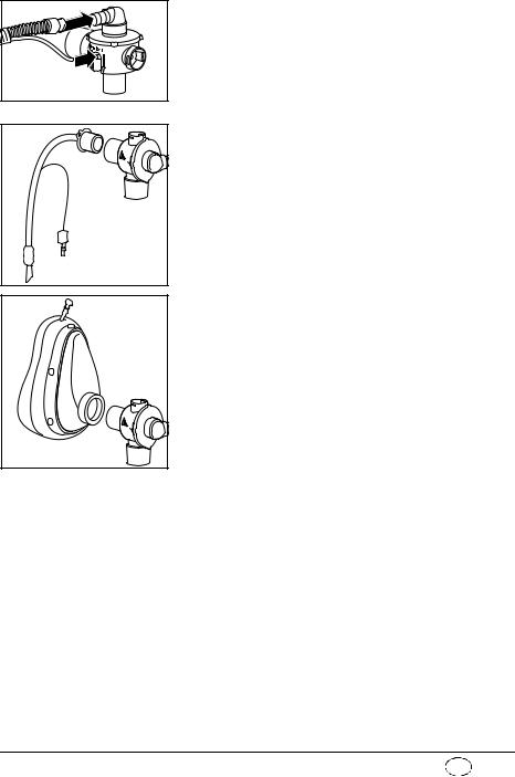
3.Plug the other end of the ventilation tube and the pressure measurement tube onto the patient valve.
4.If the patient is intubated, insert the patient valve into the tube,
or
Position 
>PSU<134°
if a mask is being used for ventilation, insert the patient valve into the connector on the mask. (This is identical with the connector on the tube.)
HME-Filter
If a heat and moisture exchanger (HME) filter is required, this should be installed between the pa- tient-side connector on the patient valve and the tube or mask.
Always follow the manufacturer’s directions for use.
Installation EN |
23 |
Loading...