


 Loading...
MEDUMAT Transport
Emergency ventilator
MEDUMAT Transport |
|
with CO2 measurement |
WM 28400 |
MEDUMAT Transport |
|
without CO2 measurement |
WM 28300 |
Description and Operating Instructions

Contents
1. |
Overview . . . . . . . . . . . . . . . . . . . . |
. 4 |
2. |
Description . . . . . . . . . . . . . . . . . . . |
15 |
2.1 |
Intended use . . . . . . . . . . . . . . . . |
15 |
2.2 |
Applications . . . . . . . . . . . . . . . . . |
15 |
2.3 |
User qualification . . . . . . . . . . . . . |
16 |
2.4 |
Function. . . . . . . . . . . . . . . . . . . . |
16 |
3. |
Installation . . . . . . . . . . . . . . . . . . . |
18 |
3.1 Connecting oxygen cylinder . . . . . 18 3.2 Hose system . . . . . . . . . . . . . . . . . 20
3.3Accessories from other
manufacturers . . . . . . . . . . . . . . . 21
3.4Permanent installation of the unit. 23
4. Safety information . . . . . . . . . . . . . 24 5. Operation . . . . . . . . . . . . . . . . . . . . 28
5.1 Controls . . . . . . . . . . . . . . . . . . . . 28 5.2 Switching the unit on/Self-test . . . 31 5.3 Navigating in menus. . . . . . . . . . . 33 5.4 Emergency modes . . . . . . . . . . . . 35 5.5 Selecting a ventilation mode. . . . . 36
5.6Pressure-controlled ventilation
modes . . . . . . . . . . . . . . . . . . . . . 38
5.7Volume-controlled ventilation
|
modes . . . . . . . . . . . . . . . . . . . . . |
42 |
5.8 |
Other ventilation functions . . . . . . |
46 |
5.9 |
Performing ventilation . . . . . . . . . |
48 |
5.10 |
Monitoring ventilation . . . . . . . . . |
49 |
5.11 |
Alarm signals . . . . . . . . . . . . . . . . |
51 |
5.12 |
Ventilation with filters |
|
|
(not supplied with the unit) . . . . . |
52 |
5.13 |
Ending ventilation . . . . . . . . . . . . |
52 |
5.14 |
Calculating the oxygen level/ |
|
|
operating time . . . . . . . . . . . . . . . |
53 |
5.15 |
Alternative ventilation. . . . . . . . . . |
55 |
5.16 |
Changing battery during use . . . . |
55 |
5.17 |
Battery management . . . . . . . . . . |
56 |
6. |
Configuring the unit . . . . . . . . . . . . |
60 |
6.1 Automatic alarm limits . . . . . . . . . 60 6.2 Setting alarm limits. . . . . . . . . . . . 61
6.3Setting the presentation of
ventilation values (only with units with etCO2 measurement) . . . . . . 62
6.4Setting advanced respiratory
parameters . . . . . . . . . . . . . . . . . 63 6.5 “Night colors“ display mode . . . . 66
6.6Setting the display brightness
and the volume . . . . . . . . . . . . . . 67 6.7 Options . . . . . . . . . . . . . . . . . . . . 68
7. Hygienic preparation . . . . . . . . . . .70
7.1 MEDUMAT Transport . . . . . . . . . 70 7.2 Hose systems . . . . . . . . . . . . . . . . 70 7.3 Parts and accessories . . . . . . . . . . 71 7.4 Fittings . . . . . . . . . . . . . . . . . . . . 71
7.5Cleaning, disinfection and
sterilization . . . . . . . . . . . . . . . . . 72
8. Function check . . . . . . . . . . . . . . . .74
8.1 Intervals. . . . . . . . . . . . . . . . . . . . 75 8.2 Checking the system for leaks . . . 75
8.3Checking the patient valve
(only reusable hose system) . . . . . 77 8.4 Automatic function check . . . . . . 77
9. Troubleshooting . . . . . . . . . . . . . . .80
9.1 Troubleshooting . . . . . . . . . . . . . 80 9.2 Physiologic alarms . . . . . . . . . . . . 81 9.3 System alarms . . . . . . . . . . . . . . . 82
10. Maintenance . . . . . . . . . . . . . . . . . .85
10.1 MEDUMAT Transport . . . . . . . . . 85 10.2 Batteries . . . . . . . . . . . . . . . . . . . 86 10.3 Accessories . . . . . . . . . . . . . . . . . 86 10.4 Changing the suction filter . . . . . 87 10.5 Storage . . . . . . . . . . . . . . . . . . . . 88 10.6 Disposal. . . . . . . . . . . . . . . . . . . . 88
11. Product, accessories . . . . . . . . . . . .89
11.1 Standard scope of supply. . . . . . . 89 11.2 Accessories . . . . . . . . . . . . . . . . . 90 11.3 Replacement parts . . . . . . . . . . . . 93
12. Technical Data . . . . . . . . . . . . . . . .95
12.1 Specifications. . . . . . . . . . . . . . . . 95 12.2 Block diagram . . . . . . . . . . . . . . . 99
2 Contents

12.3 Separation distances . . . . . . . . . . . 99 12.4 O2 consumption of the unit . . . . 100
12.5 Possible O2 concentration with counterpressure . . . . . . . . . . . . . 100
12.6 Attainable tidal volume with counterpressure . . . . . . . . . . . . . 101
13. Warranty . . . . . . . . . . . . . . . . . . . . 102 14. Declaration of Conformity . . . . . . 103
Contents 3

1. Overview
Connections on MEDUMAT Transport |
1 Alarm display |
2 USB interface |
3 O2 inlet |
4 O2 inlet/outlet |
5 Filter compartment |
cover, air inlet |
6 Ventilation connection |
terminal |
9 External power supply unit |
8 DC connection |
7 Rechargeable |
battery |
1 Alarm display |
6 Ventilation connection terminal |
Glows to indicate alarms. |
The tube system is connected here. |
2 USB interface
Means of data transfer for servicing and maintenance purposes.
3 O2 inlet
Connection point, e.g., for an oxygen cylinder.
4 O2 inlet/outlet
At this connection point, oxygen can be extracted, e.g., using an inhalation device, or an oxygen source can be connected.
7 Rechargeable battery
Provides mobile power supply to the unit.
8 DC connection
For DC power supply via an external power supply unit or via the electrical circuit of an ambulance or rescue vehicle.
9 External power supply unit
Provides power supply to the unit via a 100V - 240V grid.
5 Filter compartment cover, air inlet
Covers the filter and ensures it is securely positioned.
4 Overview
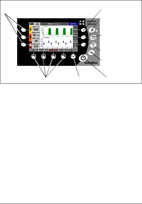
Controls of MEDUMAT Transport
11Function buttons for |
1 Context-dependent |
emergency ventilation |
function button |
|
2 Alarm mute button with |
|
LED |
3 Context-dependent
|
function button |
|
4 Function button for |
|
main menu |
|
5 Context-dependent |
|
function button |
|
6 Function button for |
|
100% O2 |
|
7 Function button for |
|
inspiratory O2 |
|
concentration |
|
8 On/Standby/Off |
10 Context-dependent control knobs 9 Navigation knob |
button |
1, 3, 5 Context-dependent function button
These buttons are used to set various ventilation parameters, depending on the ventilation mode selected.
2 Alarm mute button with LED
With this button, acoustic alarms can be muted briefly (for 2 minutes). If alarms are muted, the LED lights up. Visual alarms are still displayed.
4 Function button for main menu
This button calls up the main menu.
6 Function button for 100% O2
This button calls up the 100% O2 function to ventilate the patient briefly (2 minutes) with
100% O2 (FiO2 = 1.0).
7 Function button for inspiratory O2 concentration
This button calls up the O2 concentration menu. The required inspiratory O2 concentration in the respiratory gas can be set in this menu.
8 On/Standby/Off button
A short press switches the unit on and off. A long press switches it off completely.
9 Navigation knob
For navigating in menus and confirming your settings on the unit. During ventilation, this knob is to set the I:E ratio.
10 Context-dependent control knobs
For setting various parameters, depending on which ventilation mode is active. Settings made here must be confirmed with the Navigation knob.
11 Function buttons for emergency ventilation
These buttons start emergency ventilation. By pressing the buttons, preset parameters for infants, children or adults are activated.
Overview 5
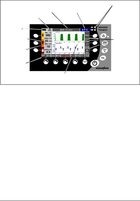
Display of MEDUMAT Transport |
1 Battery/Line operation indicators |
|
8 Indicator for inspiratory |
9 Info field |
10Mode indicator |
|
|
|
O2 concentration (FiO2) |
|
|
7 Battery |
|
|
charge |
|
|
status |
|
|
6 Numeric mea- |
|
|
surement display |
|
2 Function |
5 Function indica- |
indicator for |
|
context- |
||
tor for context- |
||
dependent |
||
dependent func- |
||
function |
||
tion buttons |
||
buttons |
||
|
||
4 Function indica- |
|
|
tor for context- |
|
|
dependent con- |
|
|
trol knobs |
3 Ventilation progress display |
|
|
1 Battery/Line operation indicators
Indicates whether the unit is being operated with the external power supply unit (upper LED) or with the internal battery (lower LED).
2Function indicator for contextdependent function buttons
The currently available function of the contextdependent function buttons is indicated here.
3 Ventilation progress display
Here, the ventilation progress is displayed in up to three graphs (ventilation pressure, ventilation flow, CO2 concentration), depending on the ventilator version. In the case of emergency ventilation, a pressue gauge is displayed.
4Function indicator for contextdependent control knobs
The currently available function of the contextdependent control knobs is indicated here.
5Function indicator for contextdependent function buttons
The three directly selectable emergency ventilation modes (infant, child, adult) are indicated here.
6 Numeric measurement display
The current measurements are indicated numerically here.
7 Battery charge status
The battery charge status is indicated here.
8 Indicator for inspiratory O2 concentration (FiO2)
The inspiratory O2 concentration (FiO2) is indicated here.
9 Info field
Information (error messages, visual alarms) about the state of the patient and the ventilator is displayed here. The time of day is also displayed in this field.
10 Mode indicator
The ventilation mode set by the user is indicated here.
6 Overview
Hose system (reusable and disposable versions available)
|
|
2 Water filter for CO2 |
|
|
|
measurement |
|
|
|
3 Connector |
|
1 Ventilation hose |
4 |
PEEP control tube |
|
|
5 |
BiCheck flow sensor |
|
11Tube protec- |
|
connection line |
|
6 |
BiCheck flow sensor |
||
tion sleeve |
|||
|
|
||
10Pressure- |
7 |
Elbow |
measurement tube 


 9 CO2 removal tube
8 Patient valve
1 Ventilation hose
The respiratory gas flows through the respiration tube to the patient valve.
2 Water filter for CO2 measurement
The water filter protects the measuring chamber of the MEDUMAT Transport against moisture from the patient's respiratory gas.
3 Connector
The measurement-tube system is connected to MEDUMAT Transport by means of this connector.
4 PEEP control tube
With this tube, MEDUMAT Transport controls the patient valve and the PEEP.
5 BiCheck flow sensor connection line
This electric lead transfers the measuring signals from the BiCheck flow sensor to the MEDUMAT Transport.
6 BiCheck flow sensor
This sensor supplies monitoring data on flow, MVe, Vte and f.
7 Elbow
The mask/tube is connected here. The elbow is removable, i.e., the mask/tube can also be connected to the BiCheck flow sensor itself, depending on the position of the patient.
8 Patient valve
Switchover between inspiration and expiration happens here.
9 CO2 removal tube
Test gas is removed via this tube if your unit is equipped with the optional CO2 measurement facility.
10 Pressuremeasurement tube
For patient-side measurement of ventilation pressure.
11 Tube protection sleeve
Protects tubes and leads against soiling and damage.
Note
Detailed information about the hose systems can be found in the “Patient Hose System“ instruction manual WM 66696.
Overview 7
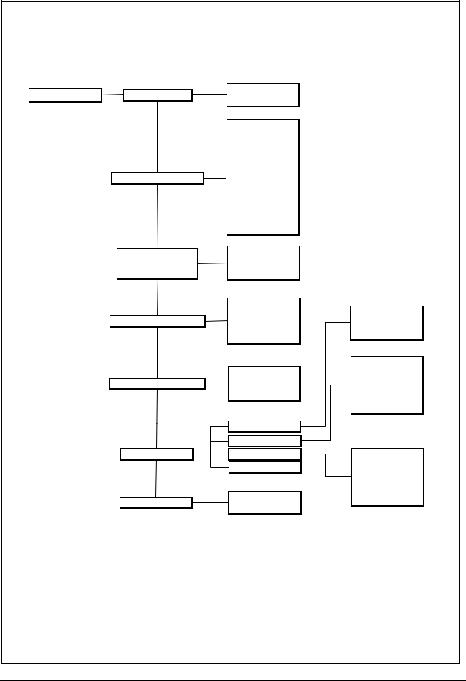
MEDUMAT Transport Main menu
Main menu |
Automatic alarm limits |
|
|
no |
|
|
|
yes |
|||
|
|
|
|
|
|
|
|
|
|
|
Automatic alarm limits |
|
|
|
|
|
Vte |
|
|
|
|
|
Vte |
|
|
|
|
|
MVe |
|
Alarm Limits |
|
|
MVe |
|
|
|
|
f |
||
|
|
|
|
|
|
|
|
|
|
|
Apnoea |
|
|
|
|
|
etCO2 |
|
|
|
|
|
etCO2 |
|
|
|
|
|
CO2i |
|
Curves |
|
|
Pressure, flow |
|
|
|
|
|
||
|
(Only CO2 measurement |
|
|
Pressure, CO2 |
|
|
|
|
|
||
|
option) |
|
|
Pressure, flow, CO2 |
|
|
|
|
|
|
Pressure ramp |
|
Advanced ventilation parameters |
|
|
Flow ramp |
|
|
|
|
Flow progress |
||
|
|
|
|
|
|
|
|
|
|
|
Trigger thresholds |
|
|
|
|
|
Brightness/Day |
|
Audio/Video |
|
|
Brightness/Night |
|
|
|
||||
|
|
|
|
|
Volume |
|
|
|
|
|
CO2 configuration |
|
|
|
|
|
Date, time |
|
Options |
|
|
|
Language |
|
|
|
|
||
|
|
|
|
|
Device data |
|
Night colours |
|
|
activate |
|
|
|
|
deactivate |
||
|
|
|
|
|
|
mmHg Vol% kPa
Year
Month
Day
Hour
Minute
Deutsch
English
Español
Italiano
…
8 Overview
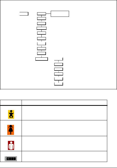
Mode menu
Mode |
|
activate |
|
NIV |
|
|
||
|
|
deactivate |
|
|
BILEVEL |
PCV
CPAP + ASB
IPPV
S-IPPV
SIMV
SPV
SVV
Preoxygenation  25 l/min
20 l/min
15 l/min
10 l/min
5 l/min
Off
Symbols used on the display
Symbol |
Meaning |
Emergency mode - Infant
Emergency mode - Child
Emergency mode - Adult
Battery status indicator
Overview 9
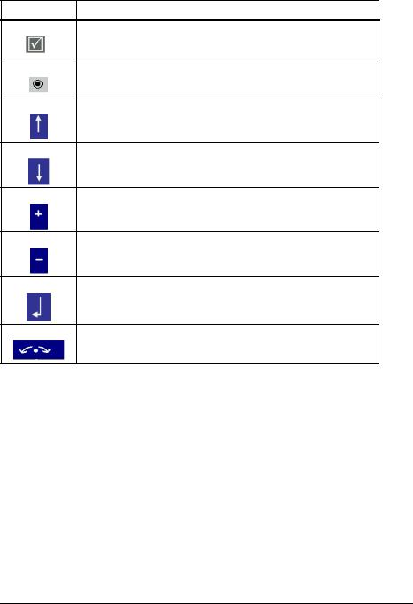
Symbol |
Meaning |
Tick box: option activated
Radio button: function selected
Navigate upwards
Navigate downwards
Increase value
Decrease value
Confirm your selection
Navigation knob active
10 Overview
Function of the controls during ventilation
Depending on the ventilation mode selected, you can set the following ventilation parameters using the controls:
|
|
|
|
|
|
|
|
|
|
7 |
|
|
|
|
|
|
|
|
|
|
|
|
|
6 |
|
|
|
|
1 |
|
2 |
3 |
4 |
|
5 |
|
|
|
|
|
|
|
|
|
|
|
|
|
|
|
|||||
|
|
|
|
|
|
|
|
|
|||||
|
|
|
|
|
|
|
|
|
|
|
|
|
|
Ventilation |
Control |
Control |
Control |
|
|
Control |
Navigation knob |
Function |
Function |
|
|||
mode |
knob 1 |
knob 2 |
knob 3 |
|
|
knob 4 |
5 |
button 6 |
button 7 |
|
|||
|
|
|
|
|
|
|
|
|
|
|
|
|
|
SVV |
|
|
|
|
|
|
|
|
|
I:E and |
|
|
|
PEEP |
pmax |
|
Vt |
|
Freq. |
Selection/ |
pASB |
Trigger |
|
||||
|
|
|
|
|
|
|
|
|
|
Confirmation |
|
|
|
|
|
|
|
|
|
|
|
|
|
|
|
|
|
SPV |
|
|
|
|
|
|
|
|
|
I:E and |
|
|
|
PEEP |
pinsp |
|
Vtmin |
|
Freq. |
Selection/ |
pASB |
Trigger |
|
||||
|
|
|
|
|
|
|
|
|
|
Confirmation |
|
|
|
|
|
|
|
|
|
|
|
|
|
|
|
|
|
CPAP + ASB |
CPAP |
- |
|
Vtmin |
|
- |
Only Selection/ |
pASB |
− |
|
|||
|
|
Confirmation |
|
||||||||||
BILEVEL |
|
|
|
|
|
|
|
|
|
I:E and |
|
|
|
PEEP |
pinsp |
|
Vtmin |
|
Freq. |
Selection/ |
pASB |
Trigger |
|
||||
|
|
|
|
|
|
|
|
|
|
Confirmation |
|
|
|
|
|
|
|
|
|
|
|
|
|
|
|
|
|
PCV |
|
|
|
|
|
|
|
|
|
I:E and |
|
|
|
PEEP |
pinsp |
|
Vtmin |
|
Freq. |
Selection/ |
- |
- |
|
||||
|
|
|
|
|
|
|
|
|
|
Confirmation |
|
|
|
|
|
|
|
|
|
|
|
|
|
|
|
|
|
IPPV |
|
|
|
|
|
|
|
|
|
I:E and |
|
|
|
PEEP |
pmax |
|
Vt |
|
Freq. |
Selection/ |
- |
- |
|
||||
|
|
|
|
|
|
|
|
|
|
Confirmation |
|
|
|
|
|
|
|
|
|
|
|
|
|
|
|
|
|
S-IPPV |
|
|
|
|
|
|
|
|
|
I:E and |
|
|
|
PEEP |
pmax |
|
Vt |
|
Freq. |
Selection/ |
- |
- |
|
||||
|
|
|
|
|
|
|
|
|
|
Confirmation |
|
|
|
|
|
|
|
|
|
|
|
|
|
|
|
|
|
SIMV |
|
|
|
|
|
|
|
|
|
I:E and |
|
|
|
PEEP |
pmax |
|
Vt |
|
Freq. |
Selection/ |
- |
- |
|
||||
|
|
|
|
|
|
|
|
|
|
Confirmation |
|
|
|
|
|
|
|
|
|
|
|
|
|
|
|
|
|
|
|
|
|
|
|
|
|
|
|
|
|
|
|
Overview 11
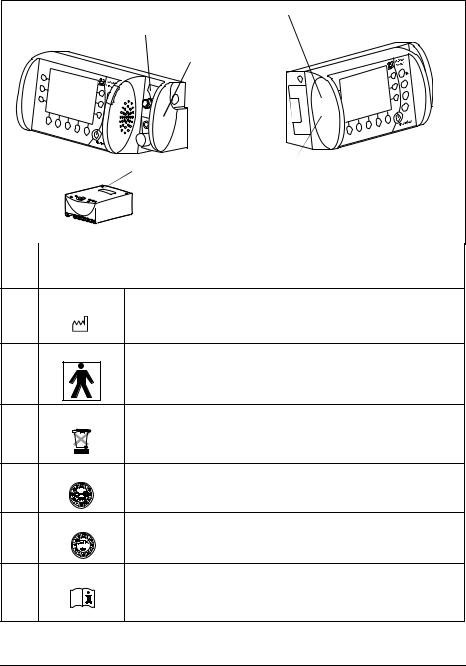
Symbols used on the unit
MEDUMAT Transport |
1 MEDUMAT Transport type plate |
5 Cover of USB interface |
|
|
4 Filter compart- |
|
ment cover |
Battery
3 Rechargeable |
2 STK and service label |
battery type plate |
|
Symbol |
Meaning |
|
|
MEDUMAT Transport type plate
1
Year manufactured
1
Type BF device
1
Do not dispose of the unit in the household waste
2 |
|
|
Service label: indicates when the next service is required. |
2 |
STK label: (only in the Federal Republic of Germany) indicates |
|
when the next safety check in accordance with §6 Medical Device |
|
Operator Ordinance (MPBetreibV) is required. |
1, 4, 5 |
|
Observe the information in the instruction manual.
12 Overview
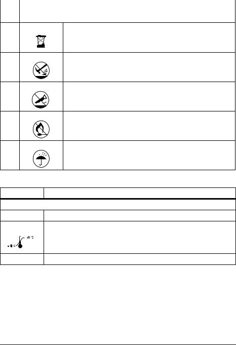
Symbol |
Meaning |
|
|
Rechargeable battery type plate
3
Do not dispose of the unit in the household waste.
3
Do not subject the unit to hard knocks or shocks.
3
Do not open the unit using force.
3
Protect the unit against heat.
3
Protect the unit against moisture.
Labeling on the packaging
Symbol |
Meaning |
MEDUMAT Transport: |
|
SN |
Serial number of the unit |
|
Permissible storage temperature: -30°C to +70°C |
3 |
|
RH % 0-95 Permissible humidity for storage: up to 95% relative humidity
Overview 13

Safety information in this manual
The safety instructions in this instruction manual are marked as follows:
Warning!
Warns of risk of injury and possible damage to the unit.
Caution!
Warns of material damage and possibly incorrect therapy results.
Note:
Offers useful tips.
14 Overview

2. Description
2.1 Intended use
The MEDUMAT Transport is an automatic oxygen emergency ventilator with additional preoxygenation and monitoring functions (pressure, flow and CO2).
MEDUMAT Transport is used for controlled and assisted, as well as for invasive and noninvasive, ventilation of persons with a respiratory volume of 50 ml upwards.
MEDUMAT Transport must only be operated when installed permanently or on approved portable systems.
2.2 Applications
MEDUMAT Transport can be used in the following cases:
Emergency
•for resuscitation at the place of the emergency
•for longer-tem use in continuing emergency situations
•for preoxygenation via a ventilation mask
Transport
•in ground, sea and air emergency medical service
•between hospital rooms and departments
•between a hospital and other locations (secondary transport)
Short-term ventilation in hospitals
•recovery room
•intensive care unit
•surgery preparation and follow-up
•emergency department
MEDUMAT Transport is also suitable for gentle ventilation of anesthetized patients (TIVA: total intravenous anesthesia).
Description 15

2.3 User qualification
MEDUMAT Transport must only be used by persons who can verify that they have the following qualifications:
•A medical qualification and training in ventilation techniques.
•Training in the use of the MEDUMAT Transport by a person authorized by WEINMANN.
Improper use may lead to serious physical injury.
2.4 Function
The unit
MEDUMAT Transport is used to treat apnea and to provide respiratory support. By means of adjustable ventilation parameters, the unit ensures uniform ventilation tailored to the patient.
Four pressure-controlled ventilation modes (SPV, CPAP + ASB, BIPAP, PCV) and four vol- ume-controlled ventilation modes (SVV, IPPV, S-IPPV, SIMV) can be selected to provide optimum patient ventilation.
In CPAP + ASB mode, the unit enables assisted spontaneous breathing with continuous positive airway pressure and respiration-controlled oxygen inhalation. In addition, the unit permits O2 inhalation for preoxygenating the patient.
The unit allows the oxygen concentration of the respiratory gas to be adjusted.
Depending on the version, the unit's large display can show up to three spirometric graphs (pressure, flow and CO2).
For emergency situations, rapid selection of default types of ventilation is possible.
16 Description

Patient Hose System
The ventilation gas is supplied to the patient via the Patient Hose System, comprising the ventilation hose and all leads necessary for comprehensive ventilation and monitoring.
The Patient Hose System is designed to permit spontaneous respiraton even if the MEDUMAT Transport malfunctions.
The Patient Hose System is available in two versions:
•Reusable hose system
•Disposable hose system
Description 17
3. Installation
As a rule, MEDUMAT Transport only has to be installed for stationary use in rescue vehicles, helicopters or aircraft. In this case, fastening sets can be supplied as accessories.
If MEDUMAT Transport is supplied complete on a portable system, the unit is ready for operation and no further installation work is required. There are separate instruction manuals for the portable systems.
Warning!
After installation, you must perform a functional check (see “8. Function check” on page 74) to ensure reliable operation.
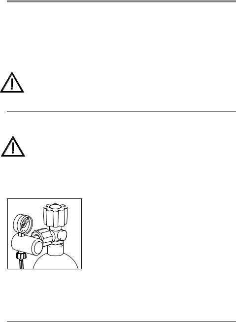
3.1 Connecting oxygen cylinder
Warning!
•Risk of explosion! Wash your hands thoroughly before doing any work on the oxygen supply. Hydrocarbon compounds (e.g. oil, grease, cleaning alcohol, hand cream or adhesive plasters) can cause explosive
reactions if they come into contact with highly compressed oxygen.
•Never use wrenches or other tools to tighten or unscrew the union nuts.
Removing the empty cylinder
1. Close the valve on the oxygen cylinder.
Switch on MEDUMAT Transport at the On/Standby/Off switch. This allows the remaining oxygen to escape and the unit is pressure-free. Only when the contents gauge on the pressure reducer indicates 0 bar, can the screwed union be undone by hand.
2. Switch MEDUMAT Transport off again.
3. Undo the screwed union at the cylinder by hand.
18 Installation
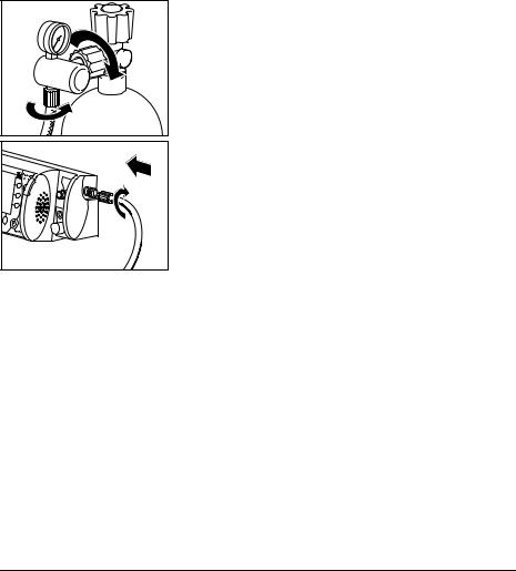
Connecting a new cylinder
1.Briefly open the valve of the new oxygen cylinder, then shut it again. This is to blow away any particles of dust.
Caution!
•Make sure that the patient is not connected up to the MEDUMAT Transport when you are establishing the gas supply. Otherwise, the unit’s automatic self-test will lead to incorrect results.
•When doing this, hold the valve opening away from your body in such a way that any flying particles cannot injure yourself or other people!
2. Screw the pressure reducer to the cylinder valve using the knurled union nut. Tighten the union nut by hand.
3. Screw the pressure hose onto the outlet of the pressure reducer (if not already connected) using the G 3/8 union nut.
4. Screw the other end of the pressure hose to the compressed gas connection of the MEDUMAT Transport (if not already connected).
Connecting a second oxygen source
Caution!
•Risk of insufficient oxygen supply
Two oxygen sources can be connected to this unit simultaneously. Make sure that only one oxygen source is open at any given time and that there is no gas reflux. Otherwise, one of the oxygen sources may empty itself unnoticed. Sufficient oxygen supply to the patient can then no longer be guaranteed when the unit is in use.
If desired or if foreseen in your establishment, you can connect a second oxygen source, e.g., an oxygen cylinder or a CGC to the O2 inlet/outlet (quick connector to the front of the unit).
Note:
If your unit is equipped with a DIN quick connector, no oxygen can be fed into the unit with the associated DIN gas probe. With this combination it is only possible to draw off oxygen.
Installation 19
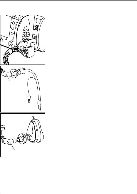
3.2 Hose system
A reusable hose system is supplied with the MEDUMAT Transport. Optionally, a disposable hose system is also available. The procedure for connecting both systems is as follows:
Connector |
Elbow
1.Press the ventilation hose onto the corresponding connection on the unit.
2.Attach the connector of the BiCheck flow sensor connection line to the corresponding connection on the unit.
3.Press the connector (contains PEEP control line, CO2 removal tube, pressure-measurement tube) onto the corresponding connection on the unit. Make sure that the connected tubes are not kinked.
Caution!
Only grip the ventilation hose by its ends. Otherwise the hose may be damaged.
4.Connect the patient valve with BiCheck flow sensor to the hose following intubation. If performing mask ventilation, attach the ventilation mask to the patient valve with the BiCheck flow sensor (identical to tube connection).
Note!
You can remove the elbow to reduce the dead space or to adapt the hose routing to suit the patient's position.
Elbow
20 Installation
Tube protection sleeve
The tube protection sleeve is pulled over the ventilation hose with connected BiCheck flow sensor. It prevents the hose system from tangling on other items of equipment and being damaged.
Water filter for CO2 removal tube
The water filter WM 97012 loses efficiency after approx. 8 hours of continuous operation, depending on the temperature, humidity and any coarse particles, such as mucus.
Change the filter after eight hours at the latest.
The filter's decreasing efficiency is indicated by the alarm message “CO2 occlusion“ on the display. This message is accompanied by a low-priority audible alarm
3.3 Accessories from other manufacturers
Caution!
The unit's USB interface is intended exclusively for use by the manufacturer or an authorized technician for servicing work. Do not connect equipment of any sort to the USB, as this will interfere with operation of the unit, putting the patient at risk.
HME filter/bacterial filter/combined HME bacterial filter
If a filter is used, install it between the patient connection of the BiCheck flow sensor (optionally with elbow) and the tube or mask. Follow the manufacturer's instructions.
Ventilation mask
Attach the ventilation mask to the BiCheck flow sensor. The mask used must have a standard connection, as per ISO 5356-1.
Laryngeal mask
You can use a laryngeal mask instead of a ventilation mask. The tube used must have a standard connection, as per ISO 5356-1.
Installation 21

Endotracheal tube
Instead of attaching the BiCheck flow sensor to a ventilation mask, you can attach it to an endotracheal tube. The tube used must have a standard connection, as per ISO 5356-1.
Tracheostomy tube
Instead of attaching the BiCheck flow sensor to a ventilation mask, you can attach it to a tracheostomy tube. The tube used must have a standard connection, as per ISO 5356-1.
Supplying oxygen to external units
You can use the O2 inlet/outlet to connect the units, modules or inhalation devices to the MEDUMAT Transport (quick connector on the front of the units).
When doing so, bear in mind that the outlet gas flow reduces the efficiency of the gas supply (see 11.5 “Required gas supply” on page 95).
22 Installation
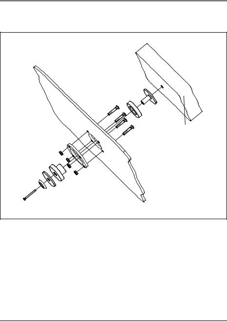
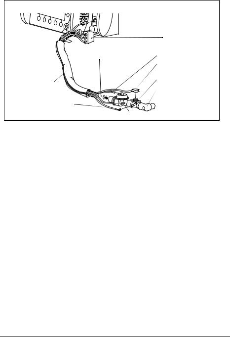
3.4 Permanent installation of the unit
If you wish to install the unit on a portable system or permanently install it in a vehicle or aircraft, you require the fastening set WM 15730.
Back panel of |
MEDUMAT Transport |
Portable system |
Installation 23

4. Safety information
Read this instruction manual carefully. It is part of the unit and must be available at all times.
For your own safety and that of your patients, and in accordance with the requirements of Directive 93/42/EEC, please observe the following points:
General
•Always carry out a functional check before using the unit (see “8. Function check” on page 74).
•Please observe the section “7. Hygienic preparation” on page 70 in order to avoid infection or bacterial contamination.
Warning!
•Risk of injury. Only use MEDUMAT Transport if you are a qualified medical professional and have received training in respiration techniques. Improper use may lead to serious physical injury.
•Risk of injury. Never leave the patient or the ventilator unattended during ventilation. Only then can you respond quickly if the patient's condition deteriorates or in the event of an alarm or malfunction. Delayed response on the part of medical personnel may lead to serious physical injury.
•Only use MEDUMAT Transport for the designated purpose (see “2.1 Intended use” on page 15).
•MEDUMAT Transport is not suitable for hyperbaric use (pressure chamber).
•The unit is not licensed for use in explosive atmospheres. The unit must not be used in combination with flammable gases or anesthetics.
•The unit is not licensed for use in poisonous or contaminated atmospheres.
•Only have modifications to the unit carried out by the manufacturer, WEINMANN, or by a technician expressly authorized by WEINMANN.
Caution!
•Do not place a switched-on cellular phone or radio closer than 1 m from the MEDUMAT Transport, as this could cause malfunctions.
•Remember that the respiratory resistance of the system as a whole may increase beyond the level specified by the standard when an HME filter
24 Safety information

(heat and moisture exchanger), a bacterial filter or a combined HME bacterial filter is used.
•When operating the unit with the power supply unit, always connect the unit to an easily accessible outlet so that it can be unplugged quickly in the event of a malfunction.
•When operating the unit with the power supply unit, make sure that the power cord cannot cause anyone to trip or cause any obstruction. If necessary, do not use an external power supply, but operate the unit with the battery instead.
•When operating the unit with the 12 V supply cord, always connect the unit to an easily accessible vehicle electrical system receptacle so that it can be unplugged quickly in the event of a malfunction.
•When operating the unit with the 12 V supply cord, make sure that the cord cannot cause anyone to trip or cause any obstruction. If necessary, do not use the vehicle electrical system, but operate the unit with the battery instead.
•A spare unit must always be kept ready for use in case of failure.
•After using the unit in a dusty environment (e.g., a gravel plant), change the suction filter, as described in the section “10.4 Changing the suction filter” on page 87.
Safe handling of oxygen
Warning!
•Risk of explosion! In combination with combustible substances (grease, oil, alcohol etc.), highly compressed oxygen may give rise to spontaneous explosive reactions.
•Risk of fire! If only the O2 inlet/outlet is used, close the O2 inlet on the side with a suitable cap. Otherwise, oxygen will escape from the O2 inlet on the side.
•Risk of poisoning! Highly concentrated oxygen can have a toxic effect on the patient if administered for too long and depending on the age of the patient. When ventilating with pure oxygen or an oxygen-air mixture, make sure that oxygen is only administered for an appropriate period.
•Keep the units and all screwed unions absolutely free from oil and grease.
•Be sure to wash your hands before working on the oxygen supply.
•Smoking and open flames are strictly prohibited in the vicinity of fittings containing oxygen.
Safety information |
25 |

Caution!
•When assembling the unit, and when changing cylinders, tighten all screwed unions on the oxygen cylinder and pressure reducer by hand only. Never use tools. Overtightening damages the threads and seals, resulting in leaks.
•Secure the oxygen cylinders so that they cannot fall over. If a cylinder falls on the pressure reducer or valve, these could break off, causing a violent explosion.
•Risk of insufficient oxygen supply
Two oxygen sources can be connected to this unit simultaneously. Make sure that only one oxygen source is open at any given time and that there is no gas reflux. Otherwise, one of the oxygen sources may empty itself unnoticed. Sufficient oxygen supply to the patient can then no longer be guaranteed when the unit is in use.
•Always open the cylinder valve slowly to prevent pressure hammer on the fittings.
•Do not empty oxygen cylinders completely, as this may allow moist ambient air to enter and cause corrosion.
Ventilation/Handling
•Patient and emergency ventilator must be kept under continuous observation during ventilation.
•Prolonged ventilation can lead to atrophy of the muscles (dependency of the patient on ventilation).
•Prolonged ventilation may lead to the airway drying out. Ensure adequate conditioning of the respiratory air.
•Only apply high ventilation pressures for short periods and only if medically indicated. Permanently applied high ventilation pressures can be injurious to the patient.
•Make sure that the patient valve is not covered or its function impaired, e.g. by the patient's position.
26 Safety information

Patient Hose System
Warning!
•Risk of injury. Only use the Patient Hose System if you are a qualified medical professional and have received training in respiration techniques. Improper use may lead to serious physical injury.
•The Patient Hose System must be subjected to a functional check and visual inspection by the user before use. For this, refer to the instruction manual for the Patient Hose System.
•When connecting the patient valve, check that the direction of flow of the respiratory gas is correct. Make sure that the expiration opening of the patient valve is not covered or prevented from functioning, e.g., by the patient's position.
•Only use the Patient Hose System for the purpose described. For this, refer to the instruction manual for the Patient Hose System.
•The Patient Hose System is not suitable for hyperbaric use (pressure chamber).
•Also refer to the instruction manual for the Patient Hose System.
Software
•Risks due to software errors have been minimized by means of extensive qualification measures.
Accessories/Repairs/Replacement parts
Caution!
•Protect silicone/rubber parts against UV light and prolonged direct exposure to sunlight to prevent them becoming brittle.
•We recommend that work such as inspections and repairs should be carried out by the manufacturer, WEINMANN, or by a technician expressly authorized by WEINMANN.
•If third-party items are used, functional failures may occur and fitness for use may be restricted. Biocompatibility requirements may also not be met. Please note that in such cases, any claim under warranty and liability will be voided if neither the accessories nor genuine replacement parts recommended in the instructions for use are used.
Safety information |
27 |
5. Operation
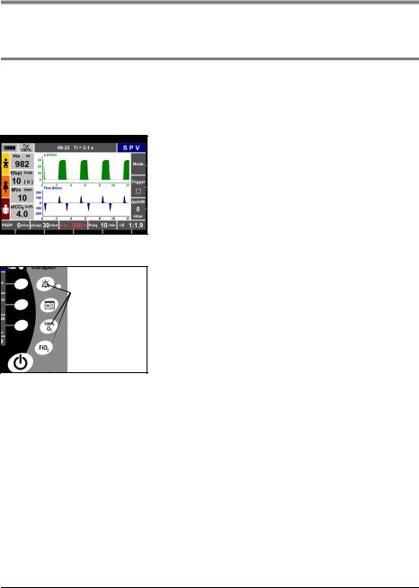
5.1 Controls
Display
The display contains the following information while the unit is in use.
•Progress of the current ventilation
•Current measurements
•Ventilation parameters set/to be set
•Current assignment of the context-dependent function buttons and control knobs
•Alarms and error messages
Function buttons with fixed assignment
 Function buttons with fixed
assignment
The fixed-assignment function buttons enable you to carry out the following actions directly:
•Mute acoustic alarms
•Call up the main menu
•Activate the “100% O2“ function
•Call up the “O2 concentration“ menu
28 Operation
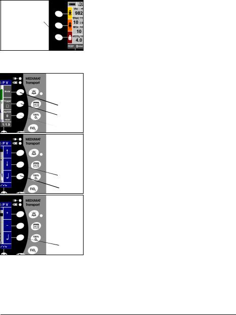
Context-dependent function buttons
Function buttons for emergency
ventilation
Contextdependent buttons
1
2
3
Contextdependent buttons
1
2
3
Contextdependent buttons
1
 2
2
3
On both sides of the display there are context-dependent function buttons for calling up the following functions:
Left side of the display:
•Selecting emergency modes (available in every ventilation mode):
–Infant (approx. 10 kg)
–Child (approx. 25 kg)
–Adult (approx. 75 kg)
Right side of the display:
•Calling up menus during ventilation:
–Button 1: Selecting a ventilation mode
–Button 2: Activating/deactivating triggers in SVV, SPV, BILEVEL modes
–Button 3: Setting the pressure level of the ASB function (ASB=Assisted Spontaneous Breathing in SVV, SPV, BILEVEL and CPAP + ASB modes)
•Navigating in a menu:
–Button 1: Up
–Button 2: Down
–Button 3: Confirm your selection
Alternatively, these settings can also be made with the navigation knob (Dual Navigation).
•Setting a parameter:
–Button 1: Increase value
–Button 2: Decrease value
–Button 3: Confirm your selection
Alternatively, these settings can also be made with the navigation knob (Dual Navigation).
Operation 29
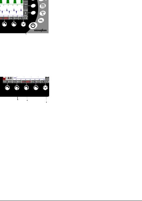
Navigation knob
|
When a menu is open, you can navigate using the |
|
|
navigation knob, as follows: |
|
|
• Turn counterclockwise: to move the selection bar |
|
|
upwards in the menu |
|
|
• Turn clockwise: to move the selection bar |
|
|
downwards in the menu |
|
Navigation knob |
• Press navigation knob to confirm your selection |
|
When no menu is open, you can carry out the following |
||
|
||
|
||
|
functions: |
•Confirm setting parameters that have been set with the context-dependent control knobs.
•Set and confirm the I:E ratio
Context-dependent control knobs
|
|
|
|
|
|
Depending on the ventilation mode selected, you can set |
|
|
|
|
|
|
|
the following parameters using the control knobs: |
|
|
|
|
|
|
|
• |
Control knob 1: PEEP, CPAP |
|
|
|
|
|
|||
|
|
|
|
|
|
• |
Control knob 2: pmax (alarm limit), Pinsp. In some |
1 |
2 |
3 |
4 |
|
5 |
|
ventilation modes, this knob has no function |
|
|||||||
|
|
|
|
|
|
• |
Control knob 3: Vt, Vte ↓ (alarm limit) |
|
|
|
|
|
|
||
|
|
|
|
|
|
• |
Control knob 4: Respiratory rate (no function in |
|
|
|
|
|
|
|
some modes) |
|
|
|
|
|
|
• |
Navigation knob 5: I:E (no function in some modes) |
If the ventilation parameters are changed using the control knobs, the corresponding parameters and the  above the navigation button will flash for 5 seconds.
Changed parameters that are not confirmed within 5 seconds by the navigation button or the contextdependent button  will not be applied.
30 Operation
Loading...