


 Loading...
Service and
Repair Instructions
VENTImotion
BiLevel-ST Home Ventilation Unit
WM 24800
VENTIlogic
BiLevel-ST Home Ventilation Unit
WM 27000

Contents
Introduction . . . . . . . . . . . . . . . . . . . . . . . . . . .3
1. Overview . . . . . . . . . . . . . . . . . . . . . . . . . . . . .4
2. Description of device . . . . . . . . . . . . . . . . . . . .10
2.1 Intended use for VENTImotion/VENTIlogic . 10 2.2 Functional description . . . . . . . . . . . . . . . 10
–Provision of therapy pressure
–Therapy modes
–Other functions
3. Hygiene treatment . . . . . . . . . . . . . . . . . . . . .11
3.1 Cleaning and disinfecting in use. . . . . . . . 11
3.2Cleaning and disinfecting on repair . . . . . 11
3.3Cleaning and disinfecting for a
patient change . . . . . . . . . . . . . . . . . . . 11 3.4 Clean and disinfect humidifier during use . . 12
3.5 Clean and disinfect humidifier on patient change . . . . . . . . . . . . . . . . . . . . . . . . 12
3.6 Clean and disinfect the VENTIpower . . . . . 12 3.7 Clean and disinfect the VENTI-O2 . . . . . . . 12
4. Test the device . . . . . . . . . . . . . . . . . . . . . . . .13
4.1 General . . . . . . . . . . . . . . . . . . . . . . . . 13 4.2 Test equipment . . . . . . . . . . . . . . . . . . . 13 4.3 Preparation for testing. . . . . . . . . . . . . . . 13
|
– Check power supply cable |
|
|
– Check housing |
|
|
– Connection to VENTIsupport |
|
4.4 |
Enter device data . . . . . . . . . . . . |
. . . . . 14 |
4.5 |
Test temperature calibration and |
|
|
calibration status . . . . . . . . . . . . . |
. . . . . 14 |
4.6 |
Test battery voltage . . . . . . . . . . . |
. . . . . 15 |
4.7 |
Test interface with the VENTIclick . . |
. . . . . 15 |
4.8 |
Check target pressure values |
|
|
5, 20 and 35 hPa. . . . . . . . . . . . |
. . . . . 15 |
4.9 |
Test flow measurement . . . . . . . . . |
. . . . . 16 |
4.10 |
Test leaktightness . . . . . . . . . . . . |
. . . . . 17 |
4.11 |
Test clock function. . . . . . . . . . . . |
. . . . . 17 |
4.12 |
Test the interface with the VENTI-O2 . . . . . 18 |
|
4.13 |
Test interface with the VENTIpower |
. . . . . 18 |
4.14 |
Test noise . . . . . . . . . . . . . . . . . |
. . . . . 19 |
4.15 |
Test all keys, the rotary knob and |
|
|
115 V mode . . . . . . . . . . . . . . . |
. . . . . 19 |
4.16 |
Test display incl. backlighting and |
|
|
contrast, the LEDs and the alarm . . |
. . . . . 20 |
4.17 |
Test equipment and accessories |
|
|
(system components) . . . . . . . . . . |
. . . . . 21 |
–Check function of humidifier
–Function check VENTI-O2
4.18 Once tests are complete. . . . . . . . . . . . . 22
5. Maintenance . . . . . . . . . . . . . . . . . . . . . . . . .23
5.1 Intervals . . . . . . . . . . . . . . . . . . . . . . . . 23 5.2 Filter change. . . . . . . . . . . . . . . . . . . . . 24
–Coarse dust filter
–Fine filter
–Reset filter change indicator
–Bacteria filter
5.3 Device cleaning . . . . . . . . . . . . . . . . . . 25 5.4 Reset maintenance symbol. . . . . . . . . . . . 26 5.5 Check the maintenance sticker . . . . . . . . . 27
5.6 Disposal . . . . . . . . . . . . . . . . . . . . . . . 27
6. Malfunctions and rectification . . . . . . . . . . . . . 28
6.1 General faults. . . . . . . . . . . . . . . . . . . . 28 6.2 Internal faults . . . . . . . . . . . . . . . . . . . . 29
–Fault output in clear text
–Coded error messages
7. Repairguide for VENTImotion/VENTIlogic . . . . 31
7.1 General . . . . . . . . . . . . . . . . . . . . . . . 31 7.2 Open device . . . . . . . . . . . . . . . . . . . . 31 7.3 Close the device . . . . . . . . . . . . . . . . . . 32 7.4 Replace mains supply unit. . . . . . . . . . . . 33 7.5 Replace power board . . . . . . . . . . . . . . 34 7.6 Replace box and filter holder. . . . . . . . . . 35 7.7 Replace fan . . . . . . . . . . . . . . . . . . . . . 37 7.8 Replace control board/display . . . . . . . . 39 7.9 Replace battery on control board . . . . . . . 42 7.10 Dismantle device outlet . . . . . . . . . . . . . 42 7.11 Replace encoder (dial) . . . . . . . . . . . . . 44 7.12 Replace fascia film . . . . . . . . . . . . . . . . 45 7.13 Replace bottom part of housing. . . . . . . . 46 7.14 Replace top part of housing . . . . . . . . . . 47
8. Spare parts . . . . . . . . . . . . . . . . . . . . . . . . . . |
48 |
|
8.1 |
List of spare parts for |
|
|
VENTImotion/VENTIlogic . . . . . . . . . . . . |
48 |
8.2 |
Spare parts required for servicing. . . . . . . |
51 |
9. Tools, test equipment and disinfectants . . . . . . 53
9.1 Tools . . . . . . . . . . . . . . . . . . . . . . . . . 53 9.2 Test equipment and fixtures . . . . . . . . . . . 53 9.3 Disinfectants . . . . . . . . . . . . . . . . . . . . . 54
10. Technical data . . . . . . . . . . . . . . . . . . . . . . . . 55
10.1 Diagram of pneumatic system . . . . . . . . . 57 10.2 Safety distances . . . . . . . . . . . . . . . . . . 57
11. Technical amendments . . . . . . . . . . . . . . . . . . 58
12. Protocols . . . . . . . . . . . . . . . . . . . . . . . . . . . . 59
12.1 Repair and service protocol . . . . . . . . . . 59 12.2 Test protocol . . . . . . . . . . . . . . . . . . . . 60

Introduction
The objective of this service and repair guide is to familiarize you, an expert, trained specialist, with the VENTImotion and VENTIlogic in terms of function, technology, servicing and repair. This will enable you to train your customers properly, eliminate faults yourself, perform the function checks specified by the operating instructions and carry out any repairs in accordance with this service and repair guide.
In the event of a claim under warranty, return the devices to Weinmann.
To allow warranty or goodwill applications to be processed, please also send the final customer's proof of purchase (invoice).
Repairs may be performed only by Weinmann or by expert, trained specialists.
You are responsible for repairs carried out yourself and for their warranty!
Use only original Weinmann spare parts for repair.
Remember:
your customer trusts you and is relying on your ability to do the job, just as you rely on Weinmann.
Note
The following information can be found in the operating instructions for the devices:
•safety rules
•setting up device
•operation
•cleaning and disinfecting in use
•warranty
Introduction 3

1. Overview
VENTImotion/VENTIlogic
|
|
|
1 Bacteria filter |
15 |
Headgear |
9 Drying adapter |
|
14 |
Mask |
|
2 Power supply |
|
|
|
|
|
|
|
cable |
13 |
Exhalation |
8 Sealing plugs (2x) |
|
|
system |
|
|
|
|
|
|
12 |
Hose system |
7 Device outlet |
3 Handle |
|
|
10 Adapter |
|
11 |
Pressure |
|
|
|
measurement |
|
4 Serial interfaces |
|
hose |
|
|
|
5 Control panel and displays |
||
|
|
||
|
|
6 Connection for humidifier |
|
71 Service label
72 Safety test label (Germany only)
18 |
Cable securing |
20 Connection for |
O2supply valve |
clip |
VENTI-O2 |
|
17 Supply |
||
19 Connection for rechargeable |
||
connection |
||
battery VENTIpower |
||
|
||
16 Filter compartment cover, air inlet |
||
21 Alarm acknowledgement key with LED
22 On/off key
23 Dial
24 Operating keys
25 Menu key
26 Humidifier key with LED
27Softstart key/manual start of analysis (VENTIlogic only)
|
30 |
VENTIclick |
31 Carrying bag |
|
|
||
|
29 Rating plate |
|
|
|
28 VENTIpower |
|
|
|
32 VENTI-O2 |
|
|
4 |
Overview |
|
|

1 Bacteria filter
To protect the device from contamination, especially if the device is being used by several patients.
2 Power supply cable
For connecting the therapy device to the mains power supply.
3 Handle
For transporting the device.
4 Serial interfaces
For connecting to devices, for display, evaluation.
5 Control panel and displays
For controlling and monitoring the therapy device and the connected accessories.
6 Connection for humidifier
For connecting the VENTIclick humidifier available as an accessory.
7 Device outlet
Respiratory air flows out from here to the patient via the hose system and nasal mask.
8 Sealing plugs (2x)
For sealing the pressure measurement hose during cleaning.
9 Drying adapter
Required to dry the hose system with the therapy device and for function check.
10 Adapter
For connecting the hose system to the device outlet.
11 Pressure measurement hose
For measuring the pressure prevailing in the mask.
12 Hose system
The air flows to the mask through the hose system. The hose system consists of creased hose, pressure measurement hose and adapter.
13 Exhalation system
Carbondioxide-enriched expired air escapes here during therapy.
14 Mask
Respiratory air at the necessary therapy pressure is administered to the patient via the mask.
15 Headgear
For correct and secure positioning of the mask.
16 Filter compartment cover, air inlet
For covering and securely positioning the coarse and fine dust filter.
17 Supply connection
This is where the power supply cable is attached to the device.
18 Cable securing clip
Prevents the device being disconnected from the power supply inadvertently.
19 Connection for rechargeable battery VENTIpower
For connecting the VENTIpower mobile power supply available as an accessory.
20 Connection for O2supply valve VENTI-O2
For connecting the VENTI-O2 oxygen supply valve available as an accessory.
21 Alarm acknowledgement key with LED
The alarm acknowledgement key is for temporarily muting alarms. The LED provides a visual display of alarms.
22 On/off key
For switching the therapy device on and off.
23 Dial
Central control of the therapy device, for navigating in the menu.
Overview 5
24 Operating keys
For rapid setting by a physician, disabled in patient mode.
25 Menu key
For switching to and fro between the standard display and the menu.
26 Humidifier key with LED
For switching the humidifier on and off or for setting humidifier stage. Six levels are available. The LED indicates whether the humidifier is activated.
27 Softstart key/manual start of analysis (VENTIlogic only)
For activating Softstart and for setting Softstart time up to the maximum Softstart time set in the menu.
In TA mode (VENTIlogic only), this key is used to start an analysis phase manually.
28 VENTIpower
Available as an accessory to provide a mobile power source for the therapy device.
29 Rating plate
Provides information about the device, such as serial number and year of manufacture.
30 VENTIclick
Available as an accessory for humidifying and heating respiratory air.
31 Carrying bag
For transporting the therapy device.
32 VENTI-O2
Available as an accessory, for introducing oxygen to the mask.
71 Service label
Indicates when maintenance is next due.
72 Safety test label (in Germany only)
Indicates when the next safety check in accordance with §6 of the German law relating to owners of medical devices [Medizinprodukte-Betreiberverordnung] is due.
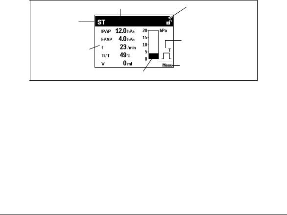
Standard display during therapy
1 Status line |
2 Padlock symbol |
7 Active ventilation mode
3 Respiratory phase switch
indicator
6 Ventilation parameters
4 Access to menu
5 Bar chart for pressure indicator
1 Status line
This is where information about the status of the device is displayed, such as filter change or maintenance due.
2 Padlock symbol
Indicates whether physician functions are enabled (padlock open) or disabled (padlock closed). The padlock is not displayed in patient mode.
3 Respiratory phase switch indicator
Indicates whether the current respiratory phase switch is spontaneous or mandatory (spontaneous: S, mandatory: T); the indicator switches from left (inspiration) to right (exhalation) depending on respiratory phase; spontaneous exspiration is shown here.
4 Access to menu
The key next to this menu item is used to switch to and fro between the menu and the standard display.
6 Overview
5 Bar chart for pressure indicator
For graphical display of pressure.
6 Ventilation parameters
The relevant current ventilation parameters are displayed depending on the active mode.
7 Active ventilation mode
The active ventilation mode is displayed at this point in the status line.
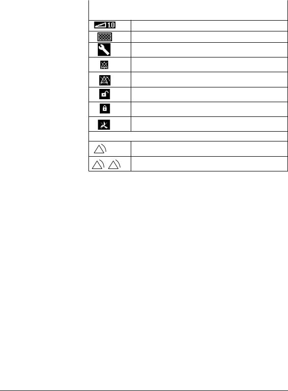
Symbols used in the display
Symbol |
Significance |
|
|
Status line:
Softstart active, remaining time faded in
Filter change required
Maintenance required
Acoustic signal for the IPAPmin and VTmin alarms mute
Alarm for IPAPmin and VTmin alarms deactivated
Physician functions enabled
Physician functions disabled
Fan off (with VENTImotion, only available from software version 6.0)
Main window
Low-priority alarm triggered
Medium-priority alarm triggered
Abbreviations used in the display
Symbol |
Significance |
|
|
Status line: |
|
|
|
TA |
TA mode active (VENTIlogic only) |
|
|
S |
S mode active |
|
|
ST |
ST mode active |
|
|
T |
T mode active |
|
|
SX |
SX mode active |
|
|
SXX |
SXX mode active |
|
|
CPAP |
CPAP mode active |
|
|
+V |
Volume compensation activated (follows mode: e.g. SXX+V) |
|
|
AA |
Device in TA mode, automatic analysis phase in progress |
|
(VENTIlogic only) |
AM |
Device in TA mode, manual analysis phase in progress |
|
(VENTIlogic only) |
Main window (monitor) |
|
|
|
IPAP |
Inspiration pressure |
|
|
EPAP |
Expiration pressure |
|
|
hPa |
Pressure shown in hectopascal; 1.01973 hPa correspond to 1 cm H2O |
|
|
Overview 7

|
|
|
Symbol |
Significance |
|
|
|
||
|
f |
Respiratory frequency |
||
|
|
|
||
|
S |
Spontaneously-triggered respiratory phase switch |
||
|
|
|
||
|
T |
Compulsorily-triggered respiratory phase switch |
||
|
|
|
||
|
Main window ("Statistics" menu item): |
|||
|
|
|
||
|
p |
Maximum rise in pressure due to volume compensation |
||
|
|
|
||
|
V |
Volume |
||
|
|
|
||
|
MV |
Per minute volume |
||
|
|
|
||
|
Leak |
System leak (mask, exspiration system, hose system, device) |
||
|
|
|
||
|
f |
Respiratory frequency |
||
|
|
|
||
|
Ti/T |
Proportion of inspiration time in a respiratory cycle |
||
|
|
|
|
|
|
|
|
|
Proportion of spontaneous inspiration (only when mean values |
|
Sins |
|||
|
displayed) |
|||
|
|
|
|
|
|
|
|
|
|
|
|
|
|
Proportion of spontaneous exspiration (only when mean values |
|
Sexs |
|||
|
displayed) |
|||
|
|
|
|
|
|
|
|
|
|
8 Overview
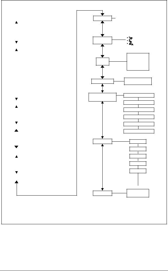
Menu structure in Physician mode
|
|
Statistics |
|
|
|
|
|
|
Actual values |
||||||
|
|
|
|
|
|
|
|
||||||||
|
|
|
|
|
|
|
|
|
|
|
Means |
||||
|
|
|
|
|
|
|
|
|
|
|
|
|
|
|
|
|
|
|
|
|
|
|
|
|
|
Appliance usage |
|||||
|
|
|
|
|
|
|
|
|
|
|
|
|
|
|
|
|
|
|
|
|
|
|
|
|
|
TA statistics |
|||||
|
|
|
|
|
|
|
|
|
|
(VENTIlogic only) |
|||||
|
|
|
|
|
|
|
|
|
|
|
|
|
|
|
|
|
|
|
|
|
|
|
|
|
|
|
|
|
|
|
|
|
|
Mode |
|
|
|
|
|
|
TA mode |
|
|
|
|||
|
|
|
|
|
|
|
|
|
|
|
|||||
|
|
|
|
|
|
|
|
|
|
(VENTIlogic |
|
||||
|
|
|
|
|
|
|
|
|
|||||||
|
|
|
|
|
|
|
|
|
|
only) |
|
||||
|
|
|
|
|
|
|
|
|
|
|
|
|
|
|
|
|
|
|
|
|
|
|
|
|
|
S mode |
|
|
|
||
|
|
|
|
|
|
|
|
|
|
|
|
|
|
|
|
|
|
|
|
|
|
|
|
|
|
T mode |
|
|
|
||
|
|
|
|
|
|
|
|
|
|
|
|
|
|||
|
|
|
|
|
|
|
|
|
|
ST mode |
|
|
|
||
|
|
|
|
|
|
|
|
|
|
|
|
||||
|
|
|
|
|
|
|
|
|
|
SX mode |
|
|
|
||
|
|
|
|
|
|
|
|
|
|
|
|
|
|
|
|
|
|
|
|
|
|
|
|
|
|
SXX mode |
|
||||
|
|
|
|
|
|
|
|
|
|
|
|
|
|||
|
|
|
|
|
|
|
|
|
|
CPAP mode |
|
|
|
||
|
|
|
|
|
|
|
|
|
|
|
|
|
|||
|
|
|
|
|
|
|
|
|
|
|
|
|
|
|
|
|
|
|
|
|
|
|
• On/Off/Sound off |
|
|||||||
|
|
|
|
|
|
|
|
||||||||
|
|
Alarms |
|
|
|
• IPAPmin |
|
||||||||
|
|
|
|
|
|
||||||||||
|
|
|
|
|
|
|
• Vtmin |
|
|||||||
|
|
|
|
|
|||||||||||
|
|
|
|
|
|
|
|
|
|
|
|
|
|
|
|
|
|
|
|
|
|
|
|
|
|
|
|
|
|
|
|
|
|
|
|
|
|
|
|
|
|
|
|
|
|
|
|
|
|
|
|
|
|
|
|
|
|
|
|
|
|
|
|
|
|
|
|
|
|
|
|
|
• Inspiration |
|
|
||||
|
|
Triggers |
|
||||||||||||
|
|
|
|
|
|
|
• Expiration |
|
|
||||||
|
|
|
|
|
|
|
|
|
|
|
|||||
|
|
|
|
|
|
|
|
|
|
|
|
|
|
|
|
|
|
|
|
|
|
|
|
|
|
|
|
|
|
|
|
|
|
|
|
|
|
|
|
|
|
|
|
|
|
|
|
|
|
|
|
|
|
|
|
|
|
|
|
|
|
|
|
|
|
Pressure rise |
|
|
|
|
• Inspiration |
|
|
||||||
|
|
|
|
|
|
• Expiration |
|
|
|||||||
|
|
|
|
|
|
|
|
|
|
|
|||||
|
|
|
|
|
|
|
|
|
|
|
|
|
|
|
|
|
|
|
|
|
|
|
|
|
|
|
|
||||
|
|
|
|
|
|
|
|
|
|
• On/Off |
|
||||
|
|
|
|
|
|
|
|
|
|
|
|||||
|
Volume comp. |
|
|
|
|
|
• VT |
|
|||||||
|
|
|
|
|
|
|
|
|
|||||||
|
|
|
|
|
|
|
|
|
|
• p |
|
||||
|
|
|
|
|
|
|
|
|
|
|
|
|
|
|
|
Target values
TA setting (VENTIlogic only)
Softstart
Patient mode
Device configuration
Language
Back
|
In SX mode: |
In SXX mode |
||||
|
• TTi |
• TTi |
||||
|
||||||
|
• TTi |
• TTi |
||||
|
|
|
|
|
• TTe |
|
|
|
|
|
|
|
|
|
|
|
|
|
|
|
|
|
Values to be set: |
|
|||
|
|
|
|
e |
|
|
|
|
|
|
|
||
|
|
|
|
|
||
|
|
|
|
|
|
|
|
|
|
|
|
|
|
|
|
|
|
|
|
|
|
|
|
|
|
|
|
|
|
|
|
|
|
|
•Lock on/off
•Tmax
•IPAP start
•EPAP start
Activate patient mode
Set date/time
Reset filter change counter
Reset maintenance counter
Reset device usage
Reset therapy values
Reset operating time
German
English
French
Italian
Norwegian
Back to monitor
Overview 9

2. Description of device
2.1 Intended use for VENTImotion/VENTIlogic
VENTImotion and VENTIlogic are home ventilation devices for the non-invasive, non-life support ventilation of adult patients with respiratory insufficiency in whom there is evidence of autonomous respiratory drive. This corresponds to the following clinical pictures:
•restrictive and obstructive ventilation disorders like paresis of the diaphragm, OSAS, COPD
•disorders of the respiratory mechanism like scoliosis, deformity of the thorax
•neurological, muscular and neuromuscular disorders
•central respiratory regulation disorders
VENTImotion and VENTIlogic are not suitable for life-support use.
Use the device only for the purpose described here.
2.2 Functional description
Provision of therapy pressure
An electronically-controlled fan draws in ambient air through a filter and delivers it to the device outlet. From here, the air flows through the hose system and the mask to the patient.
Sensors detect the pressure in the mask and in the hose system and also the respiratory phase switch (trigger point). The fan accordingly provides the IPAP and EPAP pressures set by the doctor.
Therapy modes
The device can be operated in the following therapy modes: CPAP, S, ST, T, SX, SXX, TA (TA with VENTIlogic only).
In time-controlled mode T and in assisted-controlled mode ST, your doctor can set respiratory frequency in the range from 6 to 45 breaths per minute and inspiration time in the range from 20 % to 67 % of the respiratory period.
In assisted modes S, SX and SXX and in assistedcontrolled mode ST, your doctor can select one of 6 trigger levels for both inspiration and exhalation. Your doctor can switch off the trigger for exhalation. Exhalation is then time-controlled.
Other functions
The Softstart function makes it easier to fall asleep. Your doctor sets initial pressures for inspiration and exhalation which continuously rise to the therapy pressures during the Softstart phase. This function can be disabled by the doctor.
The therapy device has an auto switch-on system. If this is activated, the device can be switched on
In the adaptive, controlled TA mode, the device automatically adapts to your personal breathing rhythm and supplies the therapy pressure in exactly the same rhythm.
If no breath is taken into the device in S mode, pressure is switched at a minimum frequency of 6 breaths per minute.
You can activate volume compensation. Minimum volume and maximum pressure rise are set for this purpose. If the minimum volume is undershot, the device automatically increases pressure continuously until the set maximum pressure (therapy pressure + max. pressure rise) is reached.
by a breath being taken into the mask. The device is still switched off using the on/off key  .
.
The display shows therapy mode and, depending on mode, the values currently being applied for CPAP/IPAP and EPAP and for respiratory frequency (f). Spontaneous or mechanical respiratory phase switches are also displayed and the pressure change shown in the form of a graph.
10 Description of device
3. Hygiene treatment
3.1 Cleaning and disinfecting in use
Caution!
This item is described in section “5. Hygienic treatment” of the therapy device operating instructions.
There follows a description of the hygiene treatment of the device in the event of repair and in the event of a patient change.
3.2 Cleaning and disinfecting on repair
A dealer should perform the following during a repair!
Caution!
It is essential to follow the instructions issued by the manufacturer of the disinfectant (9.3, page 54). It is recommended that you use suitable gloves for disinfecting (e.g. household rubber gloves or disposable gloves).
•Wipe down outer housing and power supply cable with TERRALIN.
•Clean hose, headgear and nasal mask in accordance with the operating instructions or replace with new parts (depending on condition).
•Open device as per item 7.2.
•Replace filters (coarse dust and fine filter).
•Clean out the inside of device housing and filter housing using a vacuum cleaner, clean extremely soiled areas.
•Close device as per item 7.3.
3.3 Cleaning and disinfecting for a patient change
If the device is to be hygiene-treated for another patient, perform the following steps.
Caution!
It is essential to follow the instructions issued by the manufacturer of the disinfectant (9.3, page 54). It is recommended that you use suitable gloves for disinfecting (e.g. household rubber gloves or disposable gloves).
•Wipe down outer housing and power supply cable with TERRALIN. Dispose of hose and mask system, headgear, exhalation system and carrying bag WM 24888 and replace with new parts.
•Open device as per section 7.2.
•Clean out the inside of the device housing, box and filter holder using a vacuum cleaner, clean extremely soiled areas.
•Replace coarse and fine dust filters 39 + 40.
•Open box 58 as per section 7.7.
•Spray-disinfect box, lid, fan, fan flap, motor bearing, fan cable, filter holder 37 and filter compartment cover 16 twice with MIKROZID LIQUID, in each case waiting the prescribed time for the product to take effect. In addition, at the start of the time for the product to take effect, wipe down accessible areas with a cloth wetted in MIKROZID LIQUID.
•Replace the following parts with new parts:
–hose system WM 24130
–filters WM 24870 and WM 24880
–pressure and flow measurement hoses WM 24324, WM 24835
–hose, pressure side WM 24852
Hygiene treatment |
11 |

–device outlet, complete, WM 24025
–labyrinths WM 24897
–decoupling tube WM 24028
–motor frame WM 24898
–cushioning insert, box WM 24874
–fan box gasket WM 24868
–filter holder gasket WM 24151
–hose, intake side WM 24809
–foam for expansion space WM 24171
–foam for filter holder WM 24155
–countersunk screw ISO 7045-M4x6- V2A-H with Tuflok
•Seal box 58 again as per section 7.7.
•Alternatively, the box 58 can be replaced by a reconditioned box as described in section "7.6 Replace box and filter holder" on
page 35.
•Insert device outlet WM 24025
•Replacing the WM 24837 control board Note: This is necessary because the flow sensor located on the control board cannot be sterilised.
•Close device as per item 7.3, disinfect outer housing and power supply cable with TERRALIN wipes.
•Reset maintenance symbol to set the maintenance indicator to "0" (see "5.4 Reset maintenance symbol" on page 26).
•Test the device.
•Delete patient data stored in the device as described in the hospital manual for the VENTImotion.
3.4 Clean and disinfect humidifier during use
This item is described in section "4. Hygiene treatment" in the VENTIclick operating instructions.
3.5 Clean and disinfect humidifier on patient change
If the device is to be hygiene-treated for another patient, perform the following steps.
•For hygiene reasons we recommend replacing plastic parts after a maximum period of use of 2 years. The spare parts list can be found in the operating instructions for the VENTIclick.
•If plastic parts and the heating element are heavily soiled or coated in limescale, offer a new device, otherwise:
proceed in accordance with section "4. Hygiene treatment" in the operating instructions for VENTIclick.
3.6 Clean and disinfect the VENTIpower
This item is described in section "4. Hygiene treatment" in the VENTIpower operating instructions.
3.7 Clean and disinfect the VENTI-O2
This item is described in section "4. Hygiene treatment" in the VENTI-O2 operating instructions.
12 Hygiene treatment

4. Test the device
4.1 General
Important!
The device must be subjected to the following test following every repair, maintenance and hygienic treatment in accordance with test instruction WM 24827 and the test protocol. The test can also be used to assist during troubleshooting.
For the therapy device, enter the operating hours and all parameters in your service protocol (see page 59).
If you find faults or deviations from target values during the test, you must not use the therapy device again until the faults are eliminated.
The possible causes of the faults and how you eliminate malfunctions can be found in section "6. Malfunctions and rectification" on page 28.
4.2 Test equipment
•Flow measurement device
•Test set WM 23465 incl. 23635 pressure measurement adapter
•PC and PC software VENTIsupport
•Converter box WM 93316
•Connecting cables WM 93312 and WM 96313
•115 V power source, e.g. travel adapter 230 V/115 V, 200 W
•Test protocol (see "12.2 Test protocol" on page 60)
4.3 Preparation for testing
Check power supply cable
1.Check the power supply cable 2. Ensure that
–the insulation is OK,
–the cable is undamaged
–and there are no loose contacts.
2.Replace the power supply cable 2 if necessary.
Check housing
Check the housing for general condition.
–If the housing is damaged or defective, replace the relevant side of the device (see "7.13 Replace bottom part of housing" on page 46/"7.14 Replace top part of housing" on page 47).
Test the device |
13 |
Connection to VENTIsupport
1.Plug the plug of the power supply cable into a socket.
2.Have the test protocol to hand.
3.Connect the serial interface of the therapy device to the PC via the converter box.
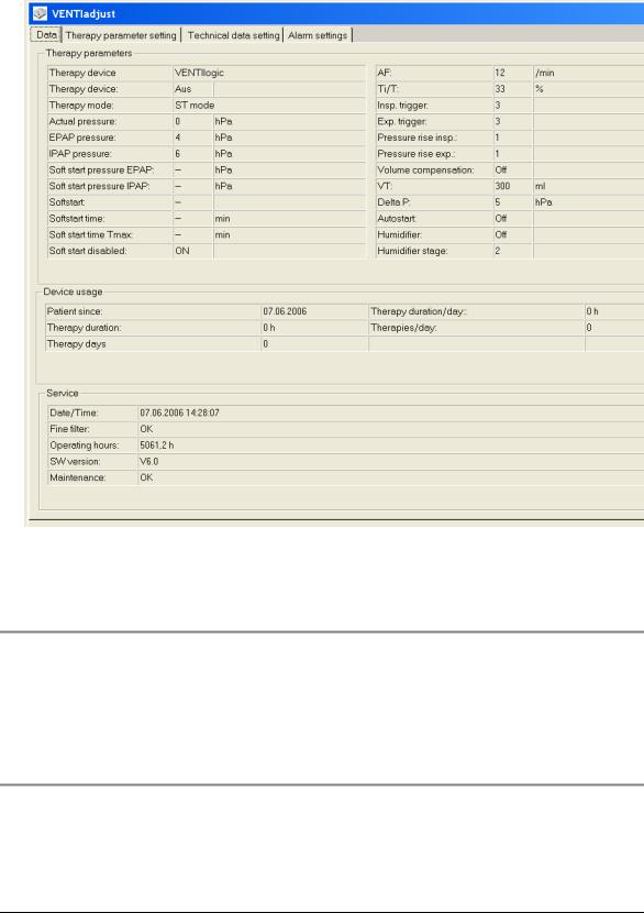
4.Start the VENTIsupport program.
5.Click on the VENTIadjust item in the menu bar.
6. Note the set therapy parameters.
4.4 Enter device data
•Enter the type, number and date of manufacture of the device in the test protocol.
4.5 Test temperature calibration and calibration status
Note
This test is not needed, as it can only be performed on a Weinmann test bench.
14 Test the device
4.6 Test battery voltage
1.Plug the red drying adapter into the device outlet of the VENTImotion.
2.Turn on the device.
Requirement: if battery voltage is sufficient, no maintenance symbol should appear in the display.
3.Replace
4.Turn off the device.
Note
If battery voltage is inadequate, replace the battery on the control board (see "7.9 Replace battery on control board" on page 42).
4.7 Test interface with the VENTIclick
•Check the function of the humidifier (see " Check function of humidifier" on page 21).
4.8 Check target pressure values 5, 20 and 35 hPa
1.Connect the hose system and the mask to the therapy device.
2.Pull a plug off the mask.
3.Connect a pressure meter to the opened connector.
4.Turn on the device.
5.Prepare the therapy device for testing by making the following settings in the “Physician” menu:
–T mode
–Frequency f = 6/min
–Ti:T = 50 %
–EPAP 5 hPA
–IPAP 35 hPA
Plug
Test the device |
15 |
6.Read off the pressure displayed by the measurement device and enter it on the protocol in the “Measuring result” column.
7.Read off the actual pressure displayed by the therapy device and enter it on the protocol in the “Mask” column.
8.Change the setting from EPAP 5 hPA to EPAP 20 hPA.
9.Read off the pressure displayed by the measurement device and enter it on the protocol in the “Measuring result” column.
10.Read off the actual pressure displayed by the therapy device and enter it on the protocol in the “Mask” column.
11.Turn off the device.
Requirement: the values must be within the tolerances quoted in the protocol.
Note
If the values are not within the quoted tolerances, replace the control board (see "7.8 Replace control board/display" on page 39).
4.9 Test flow measurement
1.Connect the device output of the therapy device to the flow measurement device using the short hose.
2.Turn on the device.
3.Prepare the VENTImotion for testing by making the following settings in the "Physician" menu:
–T mode
–frequency f = 6/min
–Ti:T = 50 %
4.Set the two pressures so that the device displays 50 and 100 l/min in the flow window. For example: IPAP=10 hPa and EPAP=5 hPa Call up the flow window by pressing the rotary knob in the "Physician" menu during operation and selecting “Flow curve” in the Display menu.
Correct the entry for pressures if necessary.
5.Enter the values displayed by the flow measurement device in the protocol. Requirement: the values must be within the tolerances quoted in the protocol.
6.Turn off the device.
Note
If the values are outside the tolerances, replace the control board (see "7.8 Replace control board/display" on page 39).
16 Test the device

4.10 Test leaktightness
1.Plug the test adapter onto the device outlet.
2.Connect the side connection to the pressure measurement device.
3.Turn on the device. Select CPAP mode in the "Physician" menu and set a pressure of
20 hPa.
4.Read off the pressure displayed by the pressure measurement device and enter it in the protocol.
Requirement: the values must be within the tolerances quoted in the protocol.
5.Turn off the device.
Note
If the value is outside tolerance, dismantle the device (see "7.2 Open device" on page 31) and check for leaks.
4.11 Test clock function
1.Connect the serial interface of the therapy device to the PC via the converter box.
2.Start the VENTIsupport program.
3.Click on the VENTIadjust item in the menu bar.
4.Select the Set technical data tab.
5.Compare "Device time" and "PC time".
Requirement: the values must change to the same extent.
Test the device |
17 |

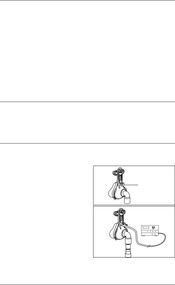
4.12 Test the interface with the VENTI-O2
1. Fit a VENTI-O2 valve to the therapy device so |
Indicator |
that it is ready to work. The indicator on top of |
|
the valve housing does not light up. |
|
2. Close the opening of the nasal mask, using your thumb or hand, for example.
3. Switch on the therapy device first, then your O2 supply. After the therapy device has been switched on, the valve opens with a soft "click" indicated by the green indicator.
4.You can now set the test flow rate on the flow display of your oxygen system. If this is not possible, first check the function of your oxygen system (is the cylinder empty, for example, or are hoses kinked?).
5.Switch the device off again. The valve audibly switches to "vent", the indicator goes out.
Note
If the VENTI-O2 valve does not react as described, perform the following measures in sequence and test again in each case.
•Use a different valve.
•Replace the connecting cable of the power board/mains supply unit (see "7.5 Replace power board" on page 34).
•Replace the power board (see "7.5 Replace power board" on page 34).
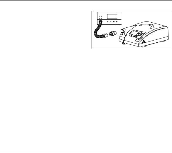
4.13 Test interface with the VENTIpower
Note
Before this test is carried out, the therapy device must have been connected to the mains power supply for at least 5 minutes.
1.Fit the VENTIpower to the therapy device so that it is ready to work therapy device. Connect the therapy device to the mains power supply.
2.Switch on the VENTIpower and then the therapy device. VENTIpower is working correctly if its displays go out, in other words, if VENTIpower switches to standby mode.
3.Now disconnect the plug of the therapy device, the device switches off. The power failure alarm sounds.
18 Test the device

VENTIpower is working correctly if its displays comes on after approx. 4 seconds and the therapy device starts working again.
4.Now restore the mains power supply to the therapy device. VENTIpower is working correctly if its displays go out, in other words, if VENTIpower switches to standby mode.
5.Switch off both devices.
4.14 Test noise
Note
This test is not needed, as it can only be performed on a Weinmann test bench.
4.15 Test all keys, the rotary knob and 115 V mode
1.Plug the red drying adapter into the device outlet.
2.Connect the device to a 115 V power source and switch on the device.
Requirement: the device must start working.
3.Press all the keys and the rotary knob to test their function.
4.Turn off the device.
Note
If the keys do not work properly, perform the following measures in sequence and test again in each case.
•Check fascia film and replace if necessary (see "7.12 Replace fascia film" on page 45).
•Replace the control board (see "7.8 Replace control board/display" on page 39).
Note
If the rotary knob does not work properly, perform the following measures in sequence and test again in each case:
•Change the encoder (see "7.11 Replace encoder (dial)" on page 44).
•Replace the control board (see "7.8 Replace control board/display" on page 39).
Note
if 115 V mode does not work properly, replace the mains supply unit (see "7.4 Replace mains supply unit" on page 33).
Test the device |
19 |

4.16 Test display incl. backlighting and contrast, the LEDs and the alarm
Note
Before this test is carried out, the VENTImotion must have been connected to the mains power supply for at least 5 minutes.
1.Switch on the device.
A beep sounds. Both LEDs come on briefly.
2.Check whether the display is easy to read with backlighting and that contrast is adequate.
Set contrast
1.Disconnect the power supply plug.
2.Press the humidifier key  and the Softstart key
  simultaneously.
3.Connect the power supply plug and the socket again.
4.Turn the rotary knob to select contrast. Activate contrast by pressing the rotary knob.
Note
If no beep is heard when you switch on, perform the following measures in sequence and test again in each case.
•Test the buzzer and replace if necessary (see "7.13 Replace bottom part of housing" on page 46).
•Replace the control board (see "7.8 Replace control board/display" on page 39).
Note
If the contrast cannot be set, perform the following measures in sequence and test again in each case.
•Check the display cable.
•Replace the display (see "7.8 Replace control board/display" on page 39).
•Replace the control board (see "7.8 Replace control board/display" on page 39).
20 Test the device
Loading...