


 Loading...
Service and
Repair Instructions
ACCUVAC Rescue
Aspirator
WM 10600

Contents
Introduction . . . . . . . . . . . . . . . . . . . . . . . . . 3
1. Overview . . . . . . . . . . . . . . . . . . . . . . . . . . . 4
2. Safety instructions . . . . . . . . . . . . . . . . . . . . . 5
2.1 Special symbols on the appliance. . . . . . .5
3. Description . . . . . . . . . . . . . . . . . . . . . . . . . . 6
3.1 Purpose . . . . . . . . . . . . . . . . . . . . . . . .6 3.2 Function . . . . . . . . . . . . . . . . . . . . . . . .6
4. Operation . . . . . . . . . . . . . . . . . . . . . . . . . . 7
5. Operating and Display Elements . . . . . . . . . . 8
5.1 Operation . . . . . . . . . . . . . . . . . . . . . .8 5.2 Service . . . . . . . . . . . . . . . . . . . . . . . .8
6. Maintenance . . . . . . . . . . . . . . . . . . . . . . . . . 9
6.1 Disposal. . . . . . . . . . . . . . . . . . . . . . . .9
7. Function checks . . . . . . . . . . . . . . . . . . . . . . . 9
7.1 Intervals . . . . . . . . . . . . . . . . . . . . . . . .9 7.2 Performing the function check . . . . . . . . .10
8. Troubleshooting . . . . . . . . . . . . . . . . . . . . . 12
9. Repairs: Information and Instructions . . . . . . 15
9.1 General . . . . . . . . . . . . . . . . . . . . . . 15 9.2 Opening the device . . . . . . . . . . . . . . 15 9.3 Closing the device . . . . . . . . . . . . . . . 16 9.4 Replacing release catch . . . . . . . . . . . 16 9.5 Replacing membrane keyboard . . . . . . 17 9.6 Changing the power pack. . . . . . . . . . 19 9.7 Initializing the power pack. . . . . . . . . . 20 9.8 Changing fuse F1 or F2 . . . . . . . . . . . 21
9.9 Checking connector between circuit
board and power pack. . . . . . . . . . . . 21 9.10 Fitting new circuit board WM 10680. . 22 9.11 Fitting new pump . . . . . . . . . . . . . . . 24 9.12 Changing fuse in vehicle plug . . . . . . . 25 9.13 Changing the muffler . . . . . . . . . . . . . 25 9.14 Electrical circuit diagram . . . . . . . . . . 26
10. Spare Parts . . . . . . . . . . . . . . . . . . . . . . . . . 27
10.1 Spare parts list . . . . . . . . . . . . . . . . . 27
11. Tools and Test Equipment . . . . . . . . . . . . . . 29
12. Technical Changes . . . . . . . . . . . . . . . . . . . 29
13. Technical Data . . . . . . . . . . . . . . . . . . . . . . 30
13.1 Safe distances . . . . . . . . . . . . . . . . . 31
14. Repair and Test Report . . . . . . . . . . . . . . . . 32
© Copyright Weinmann GmbH & Co. KG.
The content and presentation are copyright protected and may only be used by authorised Weinmann Service Partners in the course of their service operations. The content must not be reproduced or passed on to third parties. The complete documents must be returned on termination of the cooperation with Weinmann.
2

Introduction
For decades Weinmann has been developing, manufacturing and marketing appliances for emergency medical treatment, oxygen therapy and inhalation therapy.
In 1986 Weinmann launched the first ACCUVAC aspirator on the market.
The improved ACCUVAC Rescue aspirator provides users with an appliance that is an indispensable aid in many emergency health care situations. The ACCUVAC Rescue is used not only to clear the airways, as when preparing for intubation, for example, but also for removing vomited material.
In stable positioning of injured patients the ACCUVAC Rescue aspirator can be used for deflating vacuum mattresses and inflatable splints.
Using the ACCUVAC Rescue aspirator gives the user more time to look after the patient and perform other measures.
The purpose of these Service and Repair Instructions is to make sure you as an expert specialist are familiar with the ACCUVAC Rescue aspirator: its functionality and technology and how to repair it. Combined with training you have already re-
ceived from Weinmann, this makes you a member of the “authorized expert personnel” category, which means you can give your customers proper instruction, remedy faults independently, perform the final checks specified in the Operating Instructions, and carry out any repairs in accordance with these Service and Repair Instructions.
In the event of a warranty claim the ACCUVAC Rescue aspirator is to be sent to Weinmann.
So that we can process warranty claims or requests for generous treatment of complaints, please send the purchase receipt (invoice) with the appliance.
Repairs may only be carried out by Weinmann or by expert personnel.
You are responsible for any repairs you make and for the relevant warranty!
Only original Weinmann spare parts must be used for repairs.
Please remember:
Your customer trusts you and relies on your quality, just as you rely on Weinmann.
Note:
For the following information, please consult the ACCUVAC Rescue Operating Instructions:
•Safety information
•Assembly with wall bracket, Fitting accessories
•Operation
•Hygienic preparation
•Warranty
Introduction 3

Overview 4
ACCUVAC Rescue from front with disposable collection canister
4 Membrane keyboard 6 Re-usable collec-
5 |
Release catch |
tion canister |
1 On/Off 2 Vacuum control switch
3 Capacity indicator
8 Tube holder plate |
7 Motor unit |
ACCUVAC Rescue from rear without collection canister
13 Suction port |
5 Release catch |
|
12Muffler (hidden)
11 |
Power socket |
9 Loops for |
|
(hidden) |
|
|
accessory bag |
|
|
|
|
10 |
Connection cable |
|
ACCUVAC Rescue - interior |
Re-usable collection canister |
|
14 Fuse F1 15 Fuse F2 |
18 Vent tab |
|
|
19 |
Filter cover |
|
20 |
Bacteria filter |
|
21 |
Locking tab |
|
22 |
Bracing clip |
|
23 |
Secretion cover |
|
24 |
Ball (overfill guard) |
|
25 |
Sealing ring |
|
26 Nozzle with |
|
|
|
fingertip |
|
27 Aspiration tube |
|
|
28 |
Collection canister |
29 Support
17 Plug X3 16 Power pack |
10 Connection cable |
Accessories
30 Disposable bag container WM 15268
31 |
Aspiration tube with |
|
|
|
nozzle and fingertip |
|
|
32 |
Intermediate tube |
|
|
33 |
Disposable bag |
Wall bracket |
|
|
|
Accessory bag |
WM 15208 |
|
|
|
|
|
|
WM 10655 |
|
|
34 |
Vacuum tube |
|
|
35 |
T-piece |
|
|
36 |
Collection |
|
|
|
canister |
V |
|
|
37 Holder set |
Mains/charger unit |
|
|
WM 15172 |
WM 2645 |
Overview .1
2. Safety instructions
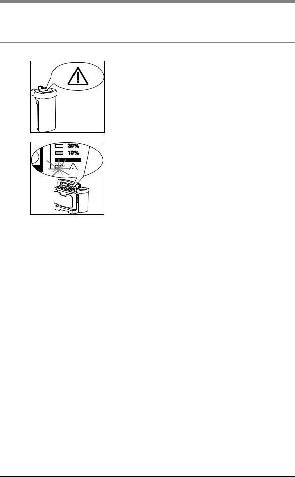
2.1 Special symbols on the appliance
The symbol on the filter cover 19 draws attention to the built-in bacteria filter 20. This must be changed or sterilized after use to prevent the risk of infection (see “5. Cleaning and disinfecting” in the operation manual).
The warning symbol in the capacity indicator 3 draws attention to the risk of complete discharging, which could damage the power pack 16. If the 10% LED lights up, it is time to recharge the ACCUVAC Rescue immediately (see “4.4 Charging the ACCUVAC Rescue” in the operation manual).
Safety instructions |
5 |
3. Description
3.1 Purpose
ACCUVAC Rescue is a mobile and portable electrically powered aspirator (suction pump).
It is used for:
•aspirating accumulations of blood, secretions and food from the oral cavity, the nose and throat region and the bronchial system;
•deflating vacuum mattresses and inflatable splints.
ACCUVAC Rescue:
•can when used by a skilled operator eliminate obstruction of the respiratory tract and hence the risk of respiratory failure;
•cuts energy consumption by reducing power output on reaching the necessary vacuum;
•can optionally be powered
–by a rechargeable internal power pack;
–or by an external DC source supplying 12.0 - 13.8 V;
•is also suitable for use in wards.
The ACCUVAC Rescue must not be used:
•in medical rooms where potential equalization is necessary
(e.g. heart surgery);
• in explosion-risk areas.
3.2 Function
An electrically powered diaphragm pump generates the vacuum necessary for aspiration.
Use the vacuum control 2 to preselect the desired vacuum between –0.05 bar and –0.8 bar. The membrane keyboard 4 is illuminated so that you can see the operating status even after dark.
Note
Once the preselected vacuum is reached, the pump switches to standby. If the vacuum changes, the pump starts up again to restore the vacuum to the preselected level.
The aspirated material passes through the aspiration tube 27 into the collection canister.
Re-usable collection canister
The re-usable collection canister 6 is fixed to the side of the motor unit and directly connected to the suction port 13 of the motor unit 7. There is thus no need for an intermediate tube.
A replaceable hydrophobic bacteria filter 20 in the secretion cover 23 prevents bacteria and droplets of moisture from finding their way into the motor unit 7 and passing into the environment via the muffler 12.
The bacteria filter is designed for multiple re-use and sterilisation.
6 Description
Important: Do not immerse the bacteria filter in disinfectant liquid, as this adversely affects its hydrophobic properties.
An overfill system prevents secretions from entering the motor unit. The ball 24 floats on the surface of the secretion until it blocks the exit.
Power supply
Power can be drawn from:
•the built-in power pack 16.
•a 12-volt vehicle electrical system, using the connecting cable.
•the mains and charger unit available as an accessory.
The capacity indicator 3 shows the charge status of the power pack in percent.
Charging of the power pack starts automatically as soon as the appliance is switched off and connected to an external power supply (see ”13. Technical Data“ on page 30).
4. Operation
ACCUVAC Rescue may only be used by trained staff instructed in aspiration techniques. Incorrect use can cause serious bodily harm.
Operation is described in the operating instructions.
Operation 7
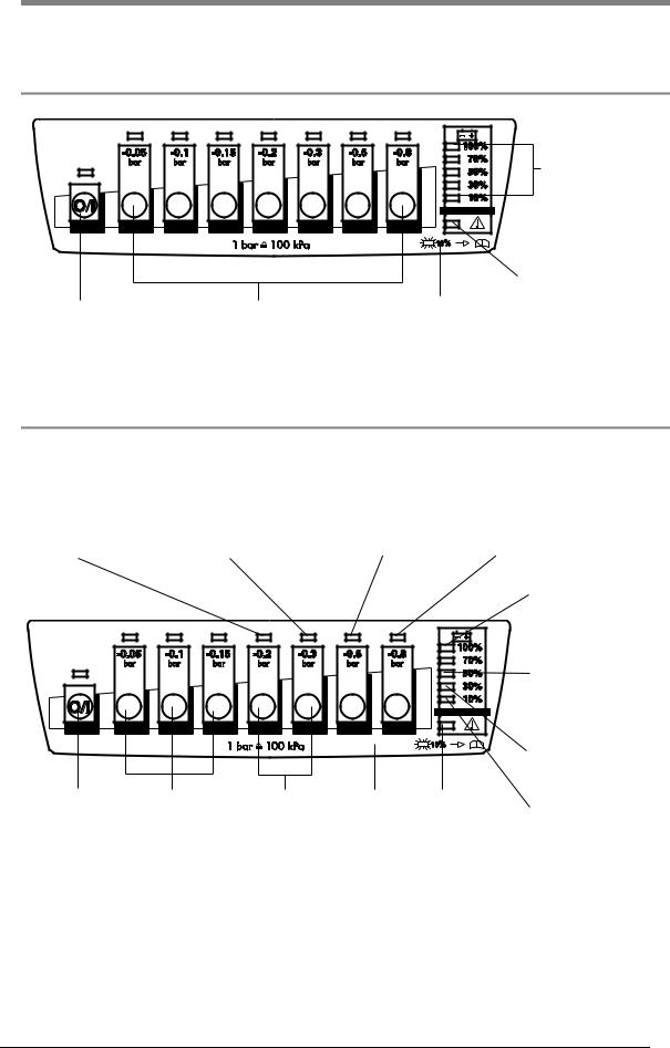
5. Operating and Display Elements
5.1 Operation
Capacity indicator
Adequate external voltage available
Main switch |
Keys for desired |
Membrane |
|
suction level |
keyboard |
5.2 Service
Bring up service display by pressing keys –0.2 and –0.3 simultaneously.
Charging was |
Charging was |
Charging was |
|
Power pack was |
||
terminated due to |
terminated due to |
terminated due to |
discharged down to |
|||
power pack |
incorrect temperature |
maximum charging |
discharging limit |
|||
overvoltage. |
of power pack. |
time being exceeded. |
voltage. |
|
||
|
|
|
|
|
|
Charging was |
|
|
|
|
|
|
terminated. |
|
|
|
|
|
|
A new power pack |
|
|
|
|
|
|
was installed. Its |
|
|
|
|
|
|
capacity is unknown. |
|
|
|
|
|
|
The last charging |
|
|
|
|
|
|
operation was |
|
|
|
|
|
|
successfully completed. |
Main switch |
Press |
Press |
Membrane |
Adequate |
Initialize power pack |
|
simultaneously |
simultaneously keyboard |
external voltage |
(if LED flashing). |
|||
|
to initialize |
for service |
|
available. |
|
|
power pack. |
display. |
|
|
|
|
|
8 Operating and Display Elements

6. Maintenance
The ACCUVAC Rescue needs no maintenance, but please be sure to observe the intervals specified for regular final checks (see ”7.1 Intervals“ on page 9).
To maintain battery operation and service life we recommend performing calibration every 8 weeks according to item 7.1.2 of the description and
operating instructions. This process involves the necessary specific battery discharging and recharging.
We recommend that you have any servicing, such as inspections and repair work, carried out by the manufacturer – Weinmann – or by expert personnel.
6.1 Disposal
Do not dispose of the unit with domestic waste. For proper waste disposal of the equipment, please contact an approved and certified waste disposal site for electronic goods. Ask your Environmental Officer or town council for the address.
7. Function checks
If the final check reveals defects or deviations from the specified values, the ACCUVAC Rescue must not be used again until the faults have been rectified.
We recommend that you always keep a stock of the following:
•Aspiration tube 27, WM 10662
•Nozzle with fingertip 26, WM 10666
•Filter 20, WM 10675
7.1 Intervals
To ensure that a properly functioning
ACCUVAC Rescue is always available, it is essential to observe the following intervals.
capacity indicator. If the capacity is 50% or less, you should recharge the power pack (see operating instructions “4.4 Charging the ACCUVAC Rescue”).
Before every use
•Perform a function check (see ”7.2 Performing the function check“ on page 10).
After every use
•Clean, disinfect and/or sterilize the unit and its parts (see operating instructions “5. Cleaning and disinfecting”);
•Perform a function check (see ”7.2 Performing the function check“ on page 10).
Every 6 weeks
•Check the power pack charge level by switching on the ACCUVAC Rescue and reading the
At least every 6 months
•Perform a function check (see ”7.2 Performing the function check“ on page 10).
•Make a visual inspection of the muffler for clogging. If it is clogged, fit a new muffler (see ”9.13 Changing the muffler“ on page 25).
After all repairs
•Clean, disinfect and/or sterilize the unit and its parts (see operating instructions “5. Cleaning and disinfecting”);
•Perform a function check (see ”7.2 Performing the function check“ on page 10).
Maintenance 9
7.2 Performing the function check
1.Assemble ACCUVAC Rescue ready for use.
2.Check that all tubes, the collection canister 28, secretion cover 23 and filter cover 19 are in perfect condition. Any damaged and/or worn parts must be replaced.
4.Switch on the ACCUVAC Rescue.
All LEDs light up for one second after switching on. After that, only those LEDs that indicate the operating status stay on. Check the charge level of the power pack by reading the capacity indicator 3. If necessary, recharge the power pack (see operating instructions “4.4 Charging the ACCUVAC Rescue”).
5.Battery test
A battery test should always be performed when there are doubts about the performance of the rechargeable battery, however at the latest two years after the battery was last changed.
Procedure:
Charge the ACCUVAC Rescue for 8 hours using the WM 2645 mains charger or for 14 hours using the WM 10750 plug-in power supply unit. Set a short interval timer to 20 minutes and start the ACCUVAC. After an operating time of 20 minutes the red LED should not be lit up and the ACCUVAC should be in operation.
If the red LED lights up after 20 minutes, or the ACCUVAC is no longer working, the battery is spent and must be replaced. In this case please replace the battery as described in section 9.6.
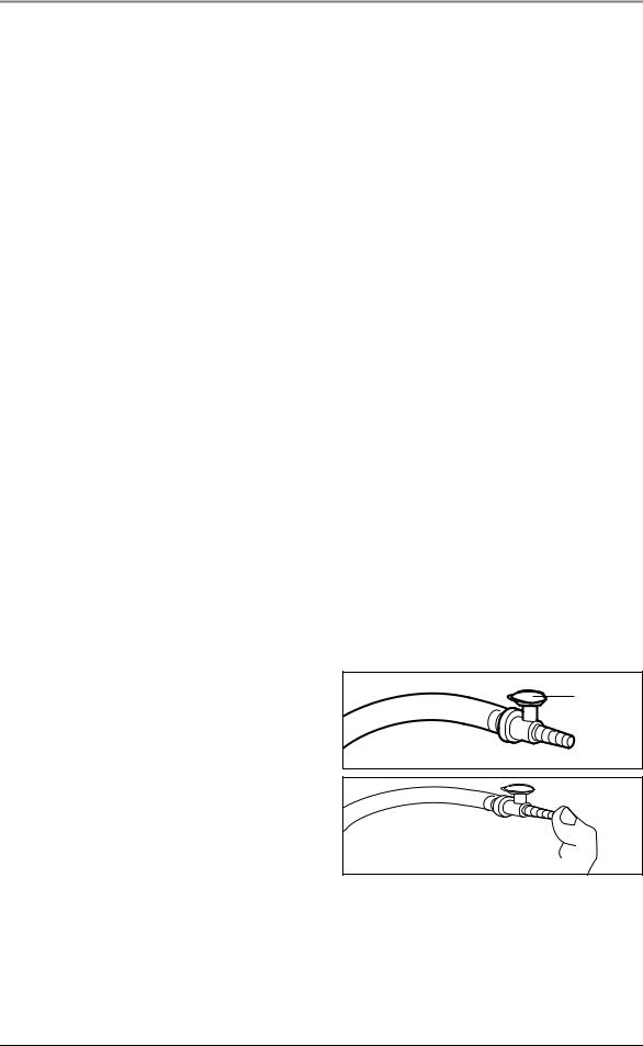
6.Insert the stopper in the fingertip.
7.Use your thumb to hold the nozzle 26 closed.
8.Switch on the aspirator and preselect the maximum vacuum of –0.8 bar. The
ACCUVAC Rescue must reach this vacuum in not more than 20 seconds. You can tell that this is the case because the pump stops.
If it takes more than 20 seconds before the pump stops, the suction capacity is reduced. Check for possible faults (see ”8. Troubleshooting“ on page 12).
3.Check that all tubes are securely connected and that the secretion cover 23 is firmly in place.
stopper
10 Function checks
9.Open the suction opening of the nozzle 26. The aspirator must start running again.
10.Preselect a vacuum of –0.3 bar.
11.Close the end of the nozzle 26 again.
12.As soon as the pump stops, select a vacuum of –0.2 bar without opening the fingertip.
The vacuum must not fall to –0.2 bar within 10 seconds.
You can tell that the vacuum is falling off by the fact that the LED above the –0.2 bar button starts flashing and the pump starts up. This means there is a leak. In this case check all tube connections and the re-usable collection canister 6.
13.Connect the test pressure gage 0 to –1 bar to the fingertip.
14.Check the accuracy of all suction levels with the test pressure gage. Start at –0.05 bar. The tolerance of the individual suction levels must not exceed +/– 0.04 bar (5% of end value on scale).
15.Remove the test pressure gage from the fingertip.
16.Switch off the ACCUVAC Rescue.
-0,6 |
-0,4 |
|
-0,2
-0,8 |
|
bar |
0 |
-1,0 O2 |
|
Function checks |
11 |
Loading...