


 Loading...
Weinmann WM 27460, WM 27420, WM 27450, WM 27410, WM 27440 Service Manual
...CPAP Units:
SOMNOcomfort 2
SOMNOcomfort 2 |
WM 24400 / WM 24465 |
SOMNOcomfort 2 with SOMNOaqua |
WM 24450 / WM 24420 |
SOMNOcomfort 2e
SOMNOcomfort 2e |
WM 24405 |
SOMNOcomfort 2 e with SOMNOaqua |
WM 24455 |
autoCPAP Units: |
|
SOMNObalance |
|
SOMNObalance, white |
WM 27400 |
SOMNObalance, white with SOMNOaqua |
WM 27440 |
SOMNObalance, anthracite |
WM 27410 |
SOMNObalance, anthracite with SOMNOaqua |
WM 27450 |
SOMNObalance e |
|
SOMNObalance e |
WM 27420 |
SOMNObalance e with SOMNOaqua |
WM 27460 |
Servicing and Repair Instructions

Content
Introduction . . . . . . . . . . . . . . . . . . . . . . . . . 3
1. Overview . . . . . . . . . . . . . . . . . . . . . . . . . . . 4
2. Description of the equipment . . . . . . . . . . . . . 8
2.1Intended use SOMNOcomfort 2 and
SOMNOcomfort 2e. . . . . . . . . . . . . . .8
2.2Intended use SOMNObalance and
SOMNObalance e . . . . . . . . . . . . . . .8
2.3Functional description SOMNOcomfort 2
and SOMNOcomfort 2e . . . . . . . . . . .9
2.4Functional description SOMNObalance
and SOMNObalance e . . . . . . . . . . . .9
3. Servicing . . . . . . . . . . . . . . . . . . . . . . . . . . 10
3.1 Intervals . . . . . . . . . . . . . . . . . . . . . .10 3.2 Filter change. . . . . . . . . . . . . . . . . . .11 3.3 Reset service symbol. . . . . . . . . . . . . .12 3.4 Disposal . . . . . . . . . . . . . . . . . . . . .12
4. Cleaning and disinfecting instructions . . . . . 13
4.1 Cleaning and disinfecting while in use. .13
4.2Cleaning and disinfecting during
repairs. . . . . . . . . . . . . . . . . . . . . . .13
4.3Cleaning and disinfecting, new patient .13
4.4Cleaning and disinfecting the
humidifier while in use . . . . . . . . . . . .14
4.5Cleaning and disinfecting the
humidifier, new patient . . . . . . . . . . . .14
5. Final test . . . . . . . . . . . . . . . . . . . . . . . . . . |
15 |
|
5.1 |
General . . . . . . . . . . . . . . . . . . . . . . |
15 |
5.2 |
Performing the test . . . . . . . . . . . . . . . |
15 |
–Preparation
–Checking the power supply cable
–Checking the power supply
–Checking the housing
–Checking the control panel and indicators
–Checking proper functionality of the therapy unit
–Checking proper function of the humidifier
6. Troubleshooting . . . . . . . . . . . . . . . . . . . . . 19
7. Repair information and repair instructions . . 21
7.1 General . . . . . . . . . . . . . . . . . . . . . .21 7.2 Tools and facilities . . . . . . . . . . . . . . .21 7.3 Sequence of repairs . . . . . . . . . . . . . .22 7.4 Opening the unit . . . . . . . . . . . . . . . .23 7.5 Closing the unit . . . . . . . . . . . . . . . . .24
7.6Replacing the main circuit board . . . . .25
7.7 Replacing the front panel foil . . . . . . . .26 7.8 Replacing the fuse . . . . . . . . . . . . . . .27 7.9 Replacing the display . . . . . . . . . . . . .27 7.10 Replacing the baffle box . . . . . . . . . . .28 7.11 Replacing the fan. . . . . . . . . . . . . . . .30 7.12 Replacing the housing, lower part. . . . .31 7.13 Replacing the housing, upper part. . . . .31
8. Replacement parts . . . . . . . . . . . . . . . . . . . 33
8.1 Replacement parts list . . . . . . . . . . . . .33
8.2Replacement parts required for
servicing . . . . . . . . . . . . . . . . . . . . .35
9. Tools, testing equipment and disinfectants . . 36
9.1 Tools . . . . . . . . . . . . . . . . . . . . . . . .36 9.2 Testing equipment . . . . . . . . . . . . . . .36 9.3 Disinfectant. . . . . . . . . . . . . . . . . . . .36
10. Technical data . . . . . . . . . . . . . . . . . . . . . . |
37 |
|
10.1 |
Specifications for SOMNOcomfort . . . . |
37 |
10.2 |
Specifications for SOMNObalance . . . |
39 |
10.3 |
Pneumatic diagram . . . . . . . . . . . . . . |
40 |
10.4 |
Electrical block diagram . . . . . . . . . . . |
40 |
10.5 |
Safety distances for SOMNOcomfort 2 |
|
|
and SOMNOcomfort 2e . . . . . . . . . . |
41 |
10.6 |
Safety distances for SOMNObalance |
|
|
and SOMNObalance e . . . . . . . . . . . |
41 |
11. Service record . . . . . . . . . . . . . . . . . . . . . . |
42 |
|
© Copyright Weinmann GmbH & Co. KG.
The content and presentation are copyright protected and may only be used by authorised Weinmann Service Partners in the course of their service operations. The content must not be reproduced or passed on to third parties. The complete documents must be returned on termination of the cooperation with Weinmann.
2

Introduction
The objective of these servicing and repair instructions is to allow you, as a well-trained and knowledgeable specialist to become acquainted with the functionality, technical specifications, servicing and repair of SOMNOcomfort 2 and SOMNOcomfort 2e as well as SOMNObalance and SOMNObalance e. This will enable you to efficiently train customers, repair malfunctions independently and to perform required servicing checks as defined in this servicing and repair instructions; it will also prepare you to perform any resulting adjustments.
In the event of a warranty claim, send the devices to WEINMANN.
In order to handle warranty or goodwill requests we will require you to submit proof of purchase (invoice) of the customer.
Repair and servicing work must be performed by Weinmann or knowledgeable, well trained specialists.
Any repairs not carried out by a qualified service engineer are your responsibility and may invalidate the warranty!
When performing servicing, only genuine Weinmann replacement parts should be used.
Please consider:
Your customers trust in your capabilities just as much as you place your confidence into Weinmann.
Note:
The following information is to be found in the units instructions for use:
•Safety instructions
•Setup of equipment
•Operation
•Hygienic preparation
•Warranty
Introduction 3

1. Overview
SOMNOcomfort 2/SOMNOcomfort 2e/SOMNObalance/SOMNObalance e
|
|
1 |
Bacteria filter |
12 |
Head gear |
H |
|
|
|
|
|
|
|
2 |
Power supply |
11 |
Mask |
|
cable |
|
|
||
|
|
3 |
Power supply |
|
|
5 Cover |
Humidifier |
10 |
Exhalation system |
4 |
|
|
|
||
9 |
Breathing tube |
8 Adapter |
|
|
|
6 Serial interface
|
|
|
|
|
7 Unit outlet |
||||||
|
|
|
|
|
|
|
|
|
|
|
|
|
|
|
|
|
|
|
|
|
|
|
|
|
13 Humidifier activated |
14 Service symbol |
|||||||||
|
|
|
|
|
|
|
|
|
|
|
|
|
|
|
|
|
|
|
|
|
|
|
|
|
|
|
15 Softstart time |
16 Automatic switch on/off |
|||||||
|
|
|
|
|
|
|
|
|
|
|
|
|
|
|
|
|
|
|
|
|
|
|
|
|
|
|
|
|
|
|
|
|
|
|
|
|
|
|
|
|
|
|
|
|
|
|
|
|
|
|
|
|
|
|
|
|
|
|
|
|
|
|
|
|
|
|
|
|
|
|
|


 17 Change filter symbol
19 On/off switch (stand-by)
20 Softstart button
18 Therapy pressure
21 Humidifier button
22Filter compartment cover, air inlet
23 Carry case


 24 DC adapter
27 Rating plate |
26 Supply connection |
25 O2 |
connection valve |
|
|
4 Overview

Legend
1 Bacteria filter (accessory)
Used to protect the patient from bacteria, particularly if the unit is being used by a number of patients.
2 Power supply cable
Connects the power supply to the mains supply.
3 Power supply
Used to supply power to the unit.
4 Humidifier
Used to heat and humidify the air flow created by the therapy unit.
5 Cover
Connects the unit outlet with the humidifier connection. Is required if a humidifier is not being used.
6 Serial interface
Connects the unit in order to display or evaluate therapy data or to connect the O2- connection valve.
7 Unit outlet
The air flows from here via the breathing tube and mask to the patient.
8 Adapter
Connects the breathing tube to the unit outlet.
9 Breathing tube
The air flows through the breathing tube to the mask.
10 Exhalation system (accessory)
Exhalation air containing carbon dioxide is diverted here during the therapy.
11 Mask (accessory)
The mask is used to provide the patient with air at the required therapy pressure.
12 Head gear (accessory)
Helps locate the mask correctly and securely.
13 Humidifier activated
This symbol appears when the humidifier is in operation. The current humidity level is displayed.
14 Service symbol
This symbol will appear after 5000 operating hours (SOMNOcomfort 2, SOMNObalance) or 10.000 operating hours (SOMNOcomfort 2e, SOMNObalance e). The unit must then be serviced.
15 Softstart time
This symbol appears when the softstart time is set or the softstart is activated.
16 Automatic switch on/off
The symbol "A" (automatic) appears when the Automatic switch on/off is active. The symbol "M" (manual) appears when the Automatic switch on/off is inactive.
17 Change filter symbol
This symbol appears every 250 operating hours. The fine filter must then be changed.
18 Therapy pressure
The therapy pressure is shown in hPa. 1 hPa = 1 mbar = 1 cm H2O.
19 On/off switch (stand-by)
Switches the therapy unit on and off.
20 Softstart button
Activates the softstart or sets the softstart time (5 - 30 minutes in 5 minute steps).
21 Humidifier button
Activates the humidifier or sets the humidifier level (6 levels).
22 Filter compartment cover, air inlet
Covers and securely locates the coarse and fine dust filters.
Overview 5
23 Carry case
For carrying the therapy unit.
24 DC adapter (accessory)
For operating the therapy unit via a DC socket (12 - 24 V).
25 O2 connection valve (accessory) For introducing oxygen into the mask.
26 Supply connection
This is the connection for the external power supply or DC adapter.
27 Rating plate
Provides information about the unit, e.g. serial number and year built.
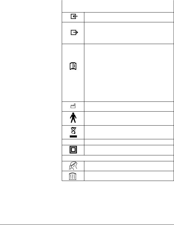
Special markings on the unit
Symbol |
Meaning |
|
|
SOMNOcomfort 2/SOMNOcomfort 2e/SOMNObalance/SOMNObalance e:
Unit inlet: allows air at room temperature to enter
Unit outlet
SOMNOcomfort 2/SOMNObalance: air escapes with 4 - 18 hPa
SOMNOcomfort 2e/SOMNObalance e: air escapes with 4 - 20 hPa
Side connection socket:
SOMNOcomfort 2/SOMNOcomfort 2e
connection for setting the therapy parameters with SOMNOadjust WM 23930 and SOMNOsupport WM 23975 by specialist staff or to control the O2 connection valve, WM 24042. Max. current consumption 163 mA.
SOMNObalance/SOMNObalance e
Serial port for setting therapy parameters using SOMNOadjust WM 23930 or SOMNOsupport WM 23975 and for specialist staff to read out raw data on the course of therapy for up to 180 therapy nights or for controlling O2 supply valve WM 24042. Max. current consumption 163 mA. Analog output for therapy pressure, flow, loss flow, relative respiratory minute volume and OPP (obstructive pressure peaks) (0 to 1 V DC).
Year built
Unit type B
Do not dispose of the unit as domestic waste.
SN Unit serial number
Unit of protection class II
SOMNOaqua (optional)
Do not use the humidifier on patients whose airways have been bypassed.
Unit is hot. Do not touch the heater rod.
6 Overview
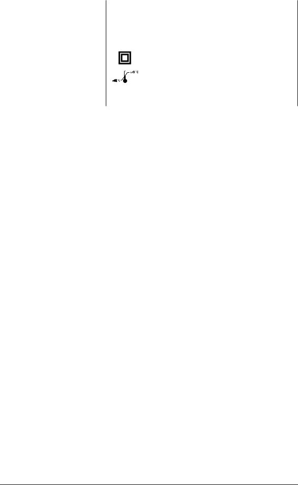
Markings on the packaging
Symbol |
Meaning |
|
|
SOMNOcomfort 2/SOMNOcomfort 2e/SOMNObalance/SOMNObalance e:
|
|
SN |
Unit serial number |
||
|
|
|
|
|
|
|
|
|
|
|
Unit of protection class II |
|
|
|
|
|
|
|
|
|
|
|
|
|
|
|
|
|
|
|
|
|
|
|
Permitted temperature for storage: - 40˚C to + 70˚C |
|
|
|
|
|
|
|
|
|
|
|
|
|
|
|
|
|
|
% 0-95 |
|
Permitted humidity for storage: max. 95% relative humidity. |
|||
|
|
|
|
|
|
Overview 7

2. Description of the equipment
2.1 Intended use SOMNOcomfort 2 and SOMNOcomfort 2e
SOMNOcomfort 2 and SOMNOcomfort 2e are CPAP-Therapy units for the treatment of sleep related respiratory disorders.
•SOMNOcomfort 2/SOMNOcomfort 2e creates continuous positive airway pressure (CPAP).
•While sleeping, the patient’s airways are stabilized by the applied pressure.
•Air pressure is administered by means of a breathing mask.
•SOMNOcomfort 2/SOMNOcomfort 2e can be used for patients age 12 and up.
Important!
SOMNOcomfort 2/SOMNOcomfort 2e can only reliably prevent airway closure when the CPAP pressure prescribed by a doctor for the specific patient has been calculated, e.g. in a sleep laboratory. Pressure is set by either using the SOMNOadjust remote control or SOMNOsupport at the units front control panel.
SOMNOcomfort 2 and SOMNOcomfort 2e are not designed for life support.
2.2 Intended use SOMNObalance and SOMNObalance e
SOMNObalance and SOMNObalance e are autoCPAP devices for treating sleep-related respiratory disorders.
•SOMNObalance/SOMNObalance e creates positive airway pressure (PAP),
•While sleeping, the patient’s airways are stabilized by the applied pressure.
•The pressure is administered by a nasal or fullface mask.
•SOMNObalance/SOMNObalance e can be used for patients age 12 and up.
•SOMNObalance/SOMNObalance e detects respiratory events and varies airway pressure accordingly.
•SOMNObalance/SOMNObalance e can be operated with or without the SOMNOaqua respiratory air humidifier.
•SOMNObalance/SOMNObalance e displays therapy data on the device.
Important!
SOMNObalance/SOMNObalance e can only reliably prevent airway blockage if the upper and lower pressure limit prescribed by the doctor on a patient-specific basis has been determined and set accordingly, for example in a sleep laboratory.
SOMNObalance and SOMNObalance e are not designed for life support.
8 Description of the equipment

2.3Functional description SOMNOcomfort 2 and SOMNOcomfort 2e
SOMNOcomfort 2 and SOMNOcomfort 2e operate according to the principle of an electrically driven flow generator, with the pressure level being controlled electronically.
•A fan draws in ambient air via a filter and conveys it to the unit outlet. From here the air flows through the breathing tube and the mask to the patient.
•A pressure sensor measures the pressure at the unit outlet and shows this in the display. The microprocessor-controlled flow generator controls the pressure to the set value and reduces fluctuations in pressure caused by breathing.
•A softstart automatic system is installed to help the patient fall asleep more easily. When the unit is switched on, the CPAP pressure starts at the initial pressure selected by the doctor and is then slowly increased to the setpoint pressure selected. The time of the pressure
increase can be adjusted between 5 and 30 minutes in 5 minute increments.
•The therapy unit offers an automatic on/off feature. The unit can then be switched on by breathing into the mask. If there is no pressure for approx. 15 seconds (e.g. because the mask has been removed), it will switch off automatically.
•The therapy parameters are set by trained personnel using the remote control system SOMNOadjust or the evaluation program SOMNOsupport.
•The therapy unit will automatically save all settings in the event of a power failure. This means that the unit does not need to be reset when power is restored.
2.4 Functional description SOMNObalance and SOMNObalance e
•A fan draws in ambient air via a filter and conveys it to the unit outlet. From here the air flows through the breathing tube and the mask to the patient.
•The exhalation system upstream of the mask
prevents the accumulation of CO2-enriched exhaled air in the tube system. During sleep, the patient's airways are braced by the air pressure generated.
•The pressure in the mask is shown in the therapy device display. The device determines a respiratory flow signal which can be output to a PSG system or also read out using SOMNOsupport.
•The device analyzes the pressure and respiratory flow signals and detects respiratory events (e.g. apneas, hypopneas, flow limitations and snoring).
•In APAP mode, therapy pressure is automatically increased in the event of obstructive respiratory events, but no higher than the upper pressure limit prescribed by the doctor. Once the events are over, therapy pressure is slowly reduced again.
•The device can be operated in APAP and CPAP modes, in each case with softPAP exhalation relief as an option.
Description of the equipment |
9 |

3. Servicing
3.1 Intervals
Servicing every 2 years or 5000 operating hours (SOMNOcomfort 2/SOMNObalance only)
Following components to be wiped down with disinfectant: |
|
||
• |
Unit housing |
|
|
• |
Filter compartment cover |
– (see chapter 4., page 13) |
|
• |
Cover |
||
|
|||
• |
Power supply |
|
|
• |
Power supply cable |
|
|
|
|
||
Replace filter |
– (see chapter 3.2, page 11) |
||
|
|
||
Check proper device operation incl. pressure |
– (see chapter 5., page 15) |
||
measuring |
|||
|
|||
|
|
||
Only if excessive soiling is present: |
|
||
Clean inside using a vacuum cleaner: |
– Opening the unit (see chapter 7.4, page 23) |
||
• |
Unit housing |
||
– Closing the unit (see chapter 7.5, page 24) |
|||
• |
Filter compartment cover |
||
|
|||
Clean areas of extreme soiling. |
|
||
|
|
|
|
Servicing every 4 years or 10,000 operating hours / change of patient
Following components to be wiped down with |
|
||
disinfectant: |
|
||
• |
Unit housing |
– (see chapter 4., page 13) |
|
• |
Filter compartment cover |
||
|
|||
• |
Power supply |
|
|
• |
Power supply cable |
|
|
|
|
||
Clean inside using a vacuum cleaner: |
|
||
• |
Unit housing |
– Opening the unit (see chapter 7.4, page 23) |
|
• |
Filter compartment cover |
– Closing the unit (see chapter 7.5, page 24) |
|
Clean areas of extreme soiling. |
|
||
|
|
||
• Replace the following parts: |
|
||
• Baffle box, assembled 53 |
|
||
• |
Cover 5 |
|
|
• |
Gasket, fan housing 66 |
– (see chapter 7.6, page 25) |
|
• Foam, lower part 59 |
|
||
• Decoupling tube, outside 50 |
|
||
• |
Adapter, assembled 8 |
|
|
|
|
||
Replace filter |
– (see chapter 3.2, page 11) |
||
|
|
||
Check proper device operation incl. pressure |
– (see chapter 5., page 15) |
||
measuring |
|||
|
|||
|
|
|
|
10 Servicing
3.2 Filter change
1.In order to prevent water from entering the SOMNOcomfort 2/SOMNOcomfort 2e/ SOMNObalance/SOMNObalance e, detach the humidifier 4 from the unit. When doing so, please refer to the included instructions for use.
2.Remove the filter compartment 22 cover on the rear of the unit.
3.Remove the coarse dust filter 68.
4.Remove the fine dust filter 67.
5.Replace the filters and close the cover on the rear of the unit.
6.Attach the humidifier where applicable. Please refer to chapter “3.4 Humidifier” of the instructions for use.
Clear the filter change indicator:
–When switching the unit on, press and hold the on/off switch 19 until the filter change indicator goes blank.
Reset the hours meter
If the fine filter was changed due to soiling before 250 operating hours, the hours meter must be reset to zero. Proceed as follows:
1.When switching the unit on, press and hold the on/off switch 19.
The filter change indicator will come on after about three seconds before going off again after another three seconds.
2.Release the on/off switch.
|
22 |
67 |
68 |
19
Servicing 11
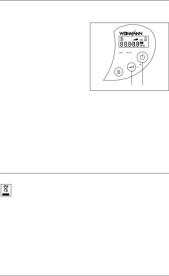
3.3 Reset service symbol
After every servicing and hygienic preparation the display’s service symbol 14 will have to be reset in order to reset the service indicator back to 0 hours.
1.To delete the service symbol, ensure the unit is switched off and press and hold softstart
button 20 until the setting option for Automatic on/off (SOMNOcomfort 2/ SOMNOcomfort 2e) or the SoftPAP stage (SOMNObalance/SOMNObalance e) appears.
2.Now, additionally press the on/off switch 19, until an S (for “key”) appears.
3. Now release both buttons.
20 19
4.SOMNOcomfort 2/SOMNOcomfort 2e: By pressing the on/off switch briefly 19 the servicing indicator can be set and deleted. SOMNObalance/SOMNObalance e: Briefly pressing on/off switch 19 allows the servicing code to be set. It is deleted by pressing softstart button 20.
5.Additionally, a new servicing label should be attached at the rear of the unit. SOMNOcomfort 2/SOMNObalance: Current year + 2
SOMNOcomfort 2e/SOMNObalance e: Current year + 4.
3.4 Disposal
Do not dispose of the unit as domestic waste. To dispose of the unit properly, please contact a licensed and certified electronic waste disposal merchant. Names and addresses can be obtained from your Environmental Officer or municipal authorities.
12 Servicing

4. Cleaning and disinfecting instructions
4.1 Cleaning and disinfecting while in use
Attention!
You will find appropriate instructions in Chapter 5. “Cleaning and disinfecting instructions” of the instructions for use SOMNOcomfort 2/SOMNOcomfort 2e/SOMNObalance/SOMNObalance e.
The following describes the cleaning and disinfecting procedures while repairing or transferring the unit to another patient.
4.2 Cleaning and disinfecting during repairs
During repairs, the following steps are to be performed by the authorized dealer!
Attention!
The instructions of disinfectant manufactures must be adhered to (9.3, page 36). We recommend that you wear suitable gloves when disinfecting the equipment (e.g. household or disposable gloves).
•Disinfect outer housing and power supply cable by wiping them down with TERRALIN.
•Clean or replace (depending on condition) breathing tube, headgear and mask according to the instructions for use.
•Open the unit according to 7.4.
•Replace 68 + 67 coarseand fine dust filters.
•Vacuum clean inner housing and filter compartment, clean areas of extreme soiling.
•Close the unit according to 7.5.
4.3 Cleaning and disinfecting, new patient
If the unit is to be disinfected and cleaned in order to transfer it to a new patient, the following steps should be taken:
Attention!
The instructions of the disinfectant manufactures must be adhered to (9.3, page 36). We recommend that you wear suitable gloves when disinfecting the equipment (e.g. household or disposable gloves).
•Disinfect outer housing, power supply and power supply cable by wiping them down with TERRALIN. Dispose of the bag, breathing tube and mask system, and replace with new components.
•Open the unit according to chapter 7.4.
•Vacuum clean inner housing and filter compartment, clean areas of extreme soiling.
•Replace 68 + 67 coarseand fine dust filters.
•Cover 5, fan housing gasket 66, foam 59, decoupling tube 50, adapter 8 must be replaced.
•Baffle box 53 should be replaced according to chapter 7.10.
•Close the unit according to chapter 7.5.
Cleaning and disinfecting instructions |
13 |

4.4 Cleaning and disinfecting the humidifier while in use
You will find corresponding instructions in chapter 4. “Disinfecting and cleaning instructions” of the instructions for use SOMNOcomfort 2(e).
4.5 Cleaning and disinfecting the humidifier, new patient
If the unit is to be disinfected and cleaned in order to transfer it to a new patient, the following steps should be taken:
•For hygiene reasons, we recommend that the plastic parts are replaced after a maximum of two years use. The replacement part list can be found in the instructions for use SOMNOcomfort 2/SOMNOaqua or SOMNObalance/SOMNOaqua.
•If plastic components and heater rod are extremely soiled or encrusted with lime you should use a new unit, otherwise
proceed according to chapter 4. “Disinfecting and cleaning instructions” of the instructions for use SOMNOcomfort 2(e).
14 Cleaning and disinfecting instructions
Loading...