


 Loading...
MODUL CapnoVol
Device for measuring respiratory parameters
WM 22400
WM 22440
WM 22460
Servicing and repair instructions

Content
Introduction . . . . . . . . . . . . . . . . . . . . . . . |
3 |
1. Overview . . . . . . . . . . . . . . . . . . . . . . . . . 4
2. Description of device . . . . . . . . . . . . . . . . . 5
2.1 Intended purpose. . . . . . . . . . . . . . . 5 2.2 Description of function . . . . . . . . . . . 5
3. Hygiene treatment . . . . . . . . . . . . . . . . . . 6
3.1 Intervals . . . . . . . . . . . . . . . . . . . . . 6
3.2MODUL CapnoVol and sensor cable . 6
3.3 Individual parts . . . . . . . . . . . . . . . . 7
4. Test the device . . . . . . . . . . . . . . . . . . . . . 8
4.1 Test material required . . . . . . . . . . . . 8 4.2 Preparation for testing. . . . . . . . . . . . 8 4.3 Enter device data . . . . . . . . . . . . . . 9 4.4 Test leaktightness . . . . . . . . . . . . . . . 9 4.5 Test device self-test . . . . . . . . . . . . . 10 4.6 Test the infrared interface . . . . . . . . 10 4.7 Test display elements . . . . . . . . . . . 10 4.8 Test input elements . . . . . . . . . . . . . 11 4.9 Test battery charging . . . . . . . . . . . 11 4.10 Test flow measurement . . . . . . . . . . 12 4.11 Test occlusion alarm . . . . . . . . . . . . 12 4.12 Test CO2 measurement . . . . . . . . . . 13 4.13 Test system clock . . . . . . . . . . . . . . 14 4.14 Documentation . . . . . . . . . . . . . . . 14
5. Servicing . . . . . . . . . . . . . . . . . . . . . . . . 15
5.1 Intervals and scope . . . . . . . . . . . . 15 5.2 Change battery . . . . . . . . . . . . . . . 16 5.3 Change O-rings of plug connection. . 16
5.4Change O-rings of oxygen duct inlet . 17
5.5 Calibrate O2 sensor . . . . . . . . . . . . 17 5.6 Storage . . . . . . . . . . . . . . . . . . . . 19 5.7 Disposal . . . . . . . . . . . . . . . . . . . 19
6. Troubleshooting . . . . . . . . . . . . . . . . . . . |
20 |
7. Repair information and repair instructions |
22 |
|
7.1 |
General. . . . . . . . . . . . . . . . . . . . |
22 |
7.2 |
Open the device . . . . . . . . . . . . . . |
22 |
7.3 |
Close the device . . . . . . . . . . . . . . |
23 |
7.4Replace the Capno connecting
adapter . . . . . . . . . . . . . . . . . . . . |
24 |
7.5 Replace Nafion tube . . . . . . . . . . . |
25 |
7.6Replace main circuit board and/or
CAP 100 circuit board . . . . . . . . . . |
25 |
7.7 Replace fuses . . . . . . . . . . . . . . . . |
28 |
7.8Replace connecting tube for oxygen
duct . . . . . . . . . . . . . . . . . . . . . . 29 7.9 Replace display circuit board. . . . . . 31 7.10 Replace infrared circuit board . . . . . 32 7.11 Replace top part of housing. . . . . . . 33 7.12 Replace bottom part of housing . . . . 34
8. Replacement parts . . . . . . . . . . . . . . . . . 35
8.1 Replacement parts list . . . . . . . . . . . 35
8.2Parts to be changed when servicing . 36
9. Tools and testing equipment . . . . . . . . . . 37
9.1 General tools . . . . . . . . . . . . . . . . 37 9.2 Special tools. . . . . . . . . . . . . . . . . 37 9.3 Testing equipment . . . . . . . . . . . . . 38
10. Technical data . . . . . . . . . . . . . . . . . . . . |
39 |
11. Service record . . . . . . . . . . . . . . . . . . . . . 41
© Copyright WEINMANN GmbH & Co. KG.
The content and presentation are copyright protected and may only be used by authorised WEINMANN Service Partners in the course of their service operations. The content must not be reproduced or passed on to third parties. The complete documents must be returned on termination of the cooperation with WEINMANN.
2

Introduction
WEINMANN has been developing, manufacturing and selling devices for emergency medicine, for oxygen therapy and for inhalation therapy for decades.
The objective of these servicing and repair instructions is to make you, an expert, familiar with the function, technology and repair of
MODUL CapnoVol. In conjunction with the training session you have already received from WEINMANN, you are now considered a “trained expert specialist”, so can properly instruct your customers, eliminate faults independently and perform the function checks specified in the instructions for use and any repairs in accordance with these servicing and repair instructions.
In the event of a claim under warranty, send MODUL CapnoVol to WEINMANN.
Please enclose the end-customer’s proof of purchase (invoice) to enable us to process warranty or goodwill claims.
Repairs and servicing work may only be performed by WEINMANN or by trained specialists.
You are responsible for repairs carried out yourself and for guaranteeing them!
Use only genuine WEINMANN replacement parts for repairs.
Please remember:
your customer trusts you and is relying on your capability in the same way as you rely on
WEINMANN.
Note
The following information can be found in the instructions for use for MODUL CapnoVol:
•safety instructions
•assembly of accessories
•operating MODUL CapnoVol
•hygiene treatment
•function check
•warranty
Introduction 3

1. Overview
MODUL CapnoVol
1 Red alarm indicator |
3 Outlet for |
2 IR interface |
oxygen duct |
6 Green charging indicator (battery charging)
5 Display |
LIFE-BASE II |
LIFE-BASE III |
|
|
LIFE-BASE Mini II |
|
|
LIFE-BASE Micro |
4 |
Operating key |
stand-alone |
|
LIFE-BASE Mini II |
LIFE-BASE II |
4 Operating |
LIFE-BASE III |
||
|
11 Inlet for |
key |
|
|
|
|
oxygen duct |
|
Stand-alone |
|
7 On/Off key |
|
|
|
LIFE-BASE Micro |
|
|
|
10 Intake opening |
8 Connection for BiCheck flow sensor |
|
for respiratory gas CO2 |
|
|
9 Connection for power supply |
|
|
measurement |
12 Luer lock elbow adapter |
13 BiCheck flow sensor |
20 Connection for CO2 extraction tube
19 Connector for BiCheck flow sensor
18 Sensor cable
17 Connector for sensor cable
21 Tube protection sleeve
16 Water filter
14 Clip for securing patient tube system
12 Luer lock elbow |
15 CO2extraction tube |
adapter |
|
22 Power supply cable 12 V
4 Overview

2. Description of device
2.1 Intended purpose
MODUL CapnoVol is a device for measuring respiratory parameters on exhalation.
The following are shown as figures:
•tidal volume (TVe)
•minute volume (MVe)
•respiratory frequency (AF)
•ratio of inspiration to exhalation (I:E)
•carbon dioxide concentration at the end of exhalation (etCO2)
The following is shown in the form of a graph:
•current carbon dioxide concentration (capnogram).
MODUL CapnoVol can be used in a permanent location or on a mobile basis both indoors and outdoors.
2.2 Description of function
Measuring volume flow
Volume flow is measured on the principle of heat energy transmission (hot-wire method). This method measures the time taken to transfer heat from one central transmission wire to the lateral reception wires. Tidal volume (TV), minute volume (MV), respiratory frequency (AF) and the ratio of inspiration to exhalation (I:E) are determined from the values measured.
Sampling and gas analysis
A small pump inside the device extracts respiratory gas from the patient's respiratory flow at an adjustable gas flow rate (secondary flow method). The respiratory gas is fed to a measuring cell via a water filter. The CO2 concentration of the dry gas is determined in the measuring cell. The measuring method used in the process is based on infrared absorption spectrometry.
CO2 measurement and display of measured values
The patient's exhalation gas is dried for technical reasons before it enters the measuring device. So that the measured values still reflect actual conditions in the moist respiratory air, MODUL CapnoVol incorporates the water vapor partial pressure of moisture-saturated air in its calculation. The value displayed thus includes the water vapor in the exhaled gas (water vapor correction).
Several measured values are determined for each breath. The CO2 concentration measured can be displayed in vol %, in mmHg or in kPa. Barometric altitude pressure is taken into account and compensated accordingly.
The CO2 concentration determined is shown in the form of a capnogram. The maximum value at the end of exhalation is called the end-tidal CO2 value (etCO2) or also final concentration of carbon dioxide on exhalation. It is displayed as a figure.
Description of device |
5 |

3. Hygiene treatment
3.1 Intervals
You must subject MODUL CapnoVol and any accessories used to a hygiene treatment after every use.
After that, always perform a function check (see Section “8. Function check” in the instructions for use).
3.2 MODUL CapnoVol and sensor cable
Warning!
Never immerse MODUL CapnoVol or the sensor cable in disinfectant or other liquids, otherwise damage to the device and thus a hazard to users and patients may result.
MODUL CapnoVol and the sensor cable are kept clean by simply washing or wiping with disinfectant.
We recommend the use of suitable gloves (e.g. household or disposable gloves) for disinfecting.
See the instructions for use for the disinfectant used. For disinfecting by wiping, we recommend TERRALIN.
Parts |
Cleaning |
Rinse cycle in a |
Disinfecting |
Sterilizing |
|
washing machine |
|||||
|
|
|
|
||
|
|
|
|
|
|
Housing for |
Wipe with a damp |
Not permitted |
Disinfect by |
Not |
|
MODUL CapnoVol |
cloth |
|
wiping |
permitted |
|
Sensor cable with |
Wipe with a damp |
Not permitted |
Disinfect by |
Not |
|
securing clips |
cloth |
|
wiping |
permitted |
6 Hygiene treatment

3.3 Individual parts
Individual parts should be cleaned, disinfected or sterilized as listed in the following table.
We recommend the use of suitable gloves (e.g. household or disposable gloves) for disinfecting.
See the instructions for use for the disinfectant used. We recommend GIGASEPT FF for disinfecting by immersion.
Warning!
The BiCheck flow sensor 13 may not be flushed through with a high-pressure water jet or compressed air, as this may damage the measuring wires.
Parts |
Cleaning |
Rinse cycle in a |
Disinfecting |
Sterilizing |
|
washing machine |
|||||
|
|
|
|
||
|
|
|
|
|
|
BiCheck flow sensor 13 |
In hot water with a |
Wash in a |
Disinfect by |
Steam- |
|
dishwasher at 65 ˚C. |
|||||
(1) |
mild detergent |
immersing (2) |
sterilize (3) |
||
|
|
Then dry thoroughly. |
|
|
|
Tube protection sleeve 21 |
Wipe with a damp |
Rinse cycle 30 ˚C, no |
Possible during |
Not |
|
cloth |
spin |
rinse cycle (4) |
permitted |
||
|
|
|
|
|
|
CO2 extraction tube 15 |
|
|
|
|
|
Water filter 16 |
Not permitted, as disposable |
|
|
||
|
|
|
|||
Luer lock elbow adapter |
|
|
|||
|
|
|
|
||
12 |
|
|
|
|
|
|
|
|
|
|
|
(1): You must remove sensor cable 18, CO2 extraction tube 15 and the ventilation tube from the BiCheck flow sensor 13, as these cannot be autoclaved.
(2): Immerse the component in dilute solution so that all surfaces, both internal and external, are wetted without bubbles. Allow full time for product to take effect. Following disinfecting, rinse all parts inside and out thoroughly with distilled water and then leave them to dry.
(3): Hot steam sterilization with devices to EN 285, temperature 134 ˚C, retention time 5 minutes.
(4): Add a suitable disinfectant additive to the rinse cycle (30 ˚C in the washing machine, no spin).
Hygiene treatment |
7 |

4. Test the device
Important!
Perform the following test on the device in accordance with test instruction WM 22401 after every repair and on servicing. The device test can also be used for troubleshooting.
If you find faults or deviations from specified values during testing, you may not use MODUL CapnoVol until the faults have been rectified.
The potential causes of the fault and how to eliminate the malfunction can be found in Section “6. Troubleshooting” on page 20.
We recommend always keeping the following in stock:
•replacement seals for device connections WM 22468, WM 22469
•Ni-Mh battery WM 22458
4.1 Test material required
•Ventilation device, e.g. MEDUMAT with the associated test set, e.g. WM 15382
•KAL Check gas WM 97061 with pressure reducer WM 97062
•PC with installed software WM 22480 from the following set WM 15681
•Set of IR adapter plus software and bracket WM 15681
•Power supply cable, 12 V, WM 22895
•Connecting cable for flow measurement WM 22420
•Measuring and leaktightness adapter WM 22868
•Current measuring adapter MODUL CapnoVol WM 22817
•CO2 absorber WM 22172
•Set for testing power supply MEDUMAT/MODULES WM 15440
•Set of tools for MEDUMAT Standard WM 15349 or syringe set WM 15359
•Volume flow measuring device (e.g. PF-300), breath volume measurement with O2 in STP mode
•Digital multimeter
•Patient tube with patient valve
•Pall filter
4.2 Preparation for testing
1.Fit MODUL CapnoVol together with a MEDUMAT ventilation device to a LIFE-BASE carrying system.
2.Connect the external power supply.
3.Connect sensor cable 18.
4.Connect 12 V power supply cable 22.
8 Test the device

5.Connect the power supply testing set MEDUMAT/MODULES WM 15440.
6.Connect CO2 extraction tube 15 with water filter.
4.3 Enter device data
Enter the device number and the date of manufacture in the test record.
4.4 Test leaktightness
4.4.1 Test oxygen duct
1.Apply a pressure of 6 bar to the inlet side of both devices when they are switched off.
2.Shut off outlet pressure.
Requirement: the drop in pressure must be ≤ 200 mbar/min.
4.4.2 Test CO2 measuring section
1. |
Push the CO2 measuring and leaktightness |
|
|
adapter onto the intake opening for respiratory |
|
|
gas CO2 measurement 10. In the process, |
|
|
ensure that the CO2 measuring and |
|
|
leaktightness adapter is correctly positioned |
10 |
|
(the pin must be in the position shown in |
|
|
|
|
|
relation to the device). |
|
2. |
Put the T-tube with syringe from set |
|
|
WM 15349/WM 15359 onto the CO2 |
|
|
measuring and leaktightness adapter. |
|
3. |
Detach the test pressure gage from the T-tube. |
|
4. |
Connect the volume flow measuring device at |
Pin |
|
the same point. |
|
5. |
Push the CO2 measuring and leaktightness |
|
|
adapter against the intake opening for |
|
|
respiratory gas CO2 measurement 10 of the |
CO2 measuring and |
|
device to ensure leaktightness. |
|
6. |
Apply a pressure of 60 mbar to the intake |
leaktightness adapter |
|
||
|
opening for respiratory gas CO2 |
T-tube with syringe |
|
measurement 10 with the device switched off. |
|
|
Requirement: the drop in pressure must be |
|
|
≤ 2 mbar/min. |
|
Test the device |
9 |

4.5 Test device self-test
1.Ensure that water filter 16 has been correctly fitted before switching on.
2.Switch on MODUL CapnoVol. Requirement: after 10 seconds, there should
not be any system alarm and the capnometry pump should have audibly started up.
4.6 Test the infrared interface
1.Align the infrared sensor above the infrared interface of MODUL CapnoVol.
2.Start the “CAPNOVOL.EXE” program as described in “Manual CapnoVol Software.pdf” on CD WM 22480.
3.Follow the instructions for reading out measured data from MODUL CapnoVol. Requirement: the measured data read out must result in meaningful characters as described in Section 4 “Measured data file” on CD
WM 22480.
4.7 Test display elements
4.7.1 Test power supply LED, alarm LED and alarm transmitter
1.Switch on the device.
2.Switch off the device and then switch back on. Requirement: the green and red LEDs must light up one after the other. At the same time, the alarm transmitter must be triggered once.
4.7.2 Test display
1.Press the “Menu” key.
2.Use the arrow keys to select the menu item “Default settings”. Press the key.
3.Use the arrow keys to select the menu item “Display”. Press the key.
10 Test the device
4.Use the arrow keys to select the menu item “Normal Inverse”. Press the key.
5.You can now use the + and – keys to switch the display between normal display and inverse display. Confirm your entries in each case by pressing .
Requirement: no image elements may be permanently on or off in either display.
4.8 Test input elements
Press all the operating keys of MODUL CapnoVol within the menu.
Requirement: all keys are detected correctly and initiate the appropriate actions.
4.9 Test battery charging
1.Connect current measuring adapter MODUL CapnoVol WM 22817, 12 V power supply and multimeter to the device.
2.Switch on MODUL CapnoVol.
3.Switch on the power supply and measure current consumption in charging mode.
Requirement: charging current at 12 V must be 1.7 A ± 0.2 A.
The power supply of mains charging devices WM 2645 and WM 2610 is higher (13.8 V). If these devices are used, the charging current should be 1.4 A ± 0.2 A.
Note
If the battery is fully charged, the device will not switch to charging mode. In other words, the above-mentioned requirement cannot be met. In this event, leave the device switched on for approx. 10 minutes and then repeat the test.
Test the device |
11 |
4.10 Test flow measurement
1.Connect MODUL CapnoVol together with a MEDUMAT ventilation device to BiCheck flow sensor 13.
2.Set breath volume on the MEDUMAT (f = approx. 20/min, AMV = approx. 9 l/min; pressure limit p = 60 mbar).
3.Switch on the compressed gas supply.
4.Switch on MEDUMAT.
5.Put the Pall filter on the test bag (for filtering flow peaks).
6.Plug BiCheck flow sensor 13 between the patient valve and the test bag with the Pall filter.
Pall filter |
I |
I |
7.Start ventilating with the MEDUMAT. Requirement: MODUL CapnoVol must display an exhalation volume TVe = 450 ± 70 ml.
4.11 Test occlusion alarm
1.Take CO2 extraction tube 15 off
MODUL CapnoVol and seal the water filter with a finger.
Requirement: the device displays an occlusion alarm.
2.Take your finger off the water filter again. Requirement: the device no longer displays an occlusion alarm.
12 Test the device
4.12 Test CO2 measurement
4.12.1 Preparation
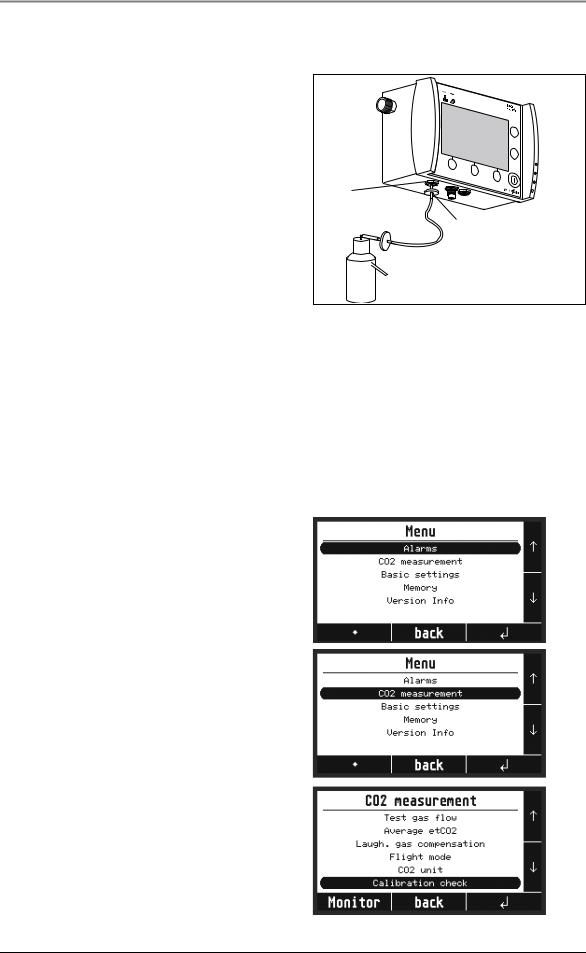
1. Plug water filter 16 onto the intake opening for respiratory gas CO2 measurement 10.
2. Connect CO2 absorber WM 22172 to water filter 16.
3. Press the CO2 absorber at least 20 times to ensure that CO2-free air is in the system.
10
16
4.12.2 Method
Important!
Use only the following components:
•the KAL Check gas (WM 97061) supplied by WEINMANN
•a suitable pressure reducer (WM 97062)
Observe an ambient temperature of approx. 20 ˚C to guarantee adequate precision in this test. It is essential to follow the instructions for use and the warning information enclosed with the KAL CHECK gas.
1.Switch on the device.
Leave MODUL CapnoVol to run for approx. 15 minutes in normal mode.
2.Press the “Menu” key. The main menu appears.
3.Use the arrow keys to select the menu item “CO2 measurement”.
4.Press the key to reach the submenu for CO2 measurement.
5.Use the ‹ key to select the “Calibration check” submenu.
6.Press the key to reach the submenu.
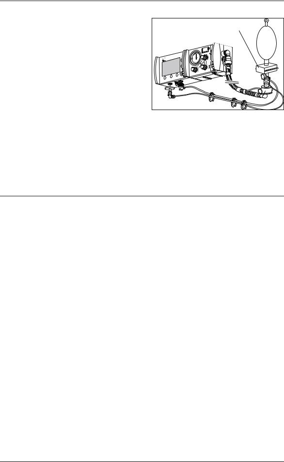
7.Disconnect CO2 extraction tube 15 from BiCheck flow sensor 13.
Test the device |
13 |

8.Connect CO2 extraction tube 15 to the Y– piece of the KAL CHECK device.
Important: the other end of the Y-piece must remain open.
9.Open the valve of the KAL CHECK gas canister far enough for the ball on the flow measuring device to be between the first and second marking ring.
Important: the gas canister must be upright for this.
10.Press the key to start the calibration check.
Remaining time is displayed while the calibration check is performed.
When the calibration check has been completed successfully, you will receive the corresponding message.
4.13 Test system clock
1. Check whether the date and time are correct in the display.
2. If necessary, set date and time as described in the instructions for use, Section “5.4 Menu default settings”.
4.14 Documentation
1.Record performance of the test on the repair and test record (copy of the form).
2.Following any repairs, send a copy of the record to WEINMANN.
14 Test the device
Loading...