

Page 1
Servicing and
repair instructions
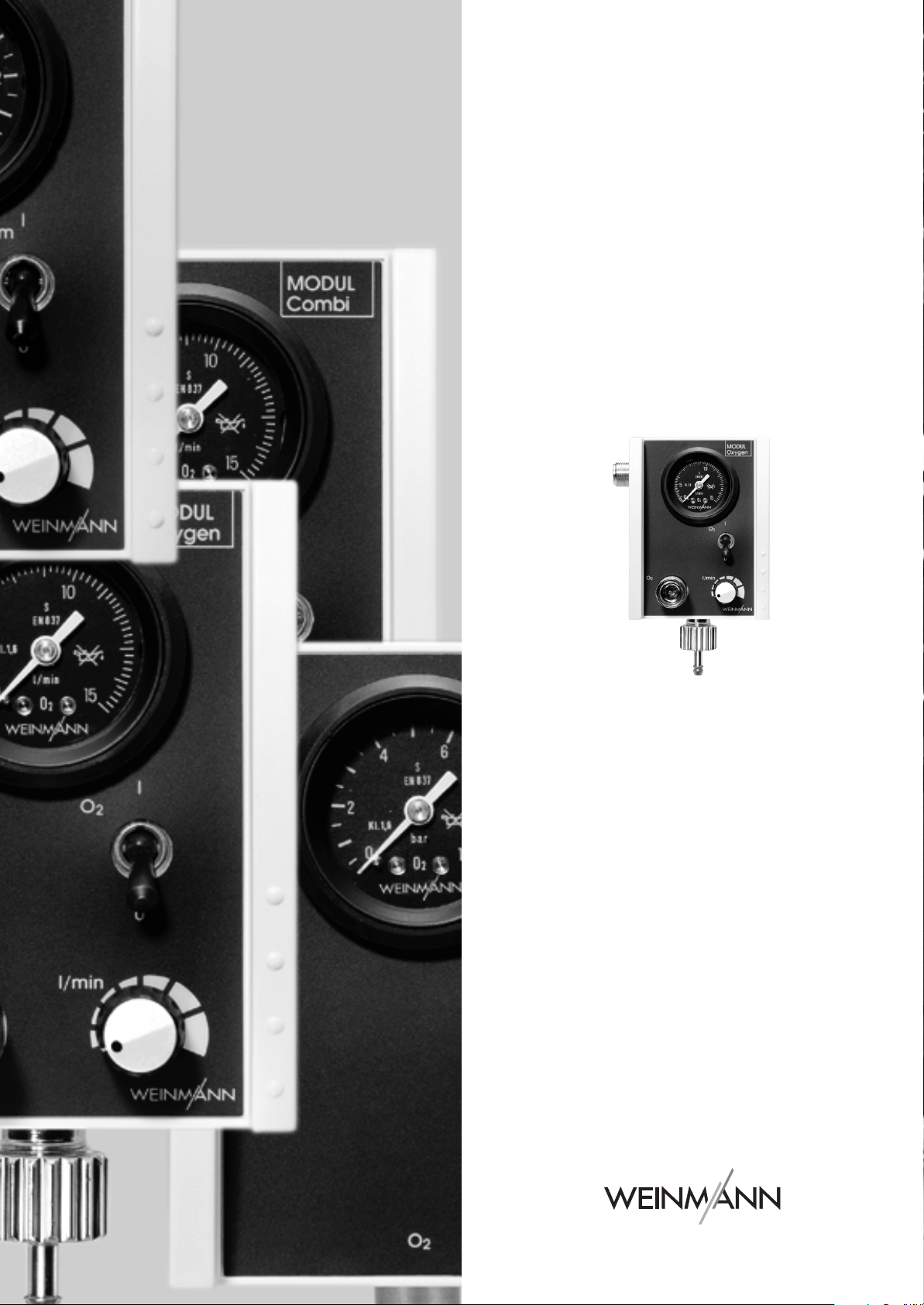
Module System
Oxygen
WM 22200
Suction
WM 22220
Combi
WM 22210
Interface
WM 22230
MODULE
MODULE
MODULE
MODULE
Page 2

Contents
Introduction
1.
Overview
2.
Description
2.1
2.2
2.3
3.
Final Check
3.1
3.2
3.3
3.4
3.5
3.6
3.7
4.
Servicing
4.1
4.2
4.3
5.
Troubleshooting
6.
Repair information and repair instructions
6.1
6.2
6.3
. . . . . . . . . . . . . . . . . . . . . . . . . .
. . . . . . . . . . . . . . . . . . . . . . . . . . .
. . . . . . . . . . . . . . . . . . . . . . . . . .
Uses
. . . . . . . . . . . . . . . . . . . . . . . . . .
Module combinations
Storage
Test resources required
Preparations for final check
Entering device data
Check for leaks in the system
Checking inhalation function
Testing vacuum
Checking aspiration function
Intervals
Servicing
Disposal
General
Oxygen MODULE
6.2.1
6.2.2
6.2.3
6.2.4
6.2.5
6.2.6
6.2.7
6.2.8
6.2.9
6.2.10
6.2.11
6.2.12
Suction
6.3.1
. . . . . . . . . . . . . . . . . . . . . . . .
. . . . . . . . . . . . . . . . . . . . . . . . . .
. . . . . . . . . . . . . . . . . . . . . . . . . . .
. . . . . . . . . . . . . . . . . . . . . . .
. . . . . . . . . . . . . . . . . . . . . .
. . . . . . . . . . . . . . . . . . . . . . .
. . . . . . . . . . . . . . . . . . . . . .
. . . . . . . . . . . . . . . . . . . . . . .
Replacing the sieve in the
oxygen inlet
Replacing the O-ring in the
oxygen outlet
Dismantling the housing
Assembling the housing
Replacing the non-return valve
in the distributor block
Replacing the pressure gauge
Replacing the tubes
Replacing the toggle switch
Replacing the quick-release
coupling
Replacing O-ring of Walther
coupling
Replacing the pressure regulator
(
MODULE Oxygen: up to Device
No. 1616;
up to Device No. 1075;
MODULE Suction: up to
Device No. 1010)
Replacing the pressure regulator
(
MODULE Oxygen: from Device
No. 1617;
from Device No. 1076;
MODULE Suction: from
Device No. 1011)
MODULE
Replacing the sieve in the
oxygen inlet
. . . . . . . . . . . . . . .
. . . . . . . . . . . . . .
. . . . . . . . . . .
. . . . . . . . . . . . . . .
. . . . . . . . . .
. . . . . . . . . .
. . . . . . . . . . . . . . . . . . .
. . . . . . . . .
. . . . . . . . . . . . . . . .
. . . . . . . . . . . . .
. . . . . . . . . . . .
. . . . . . . .
. . . . . . . . . . . . . . .
. . . . . . . . . . . . . . .
MODULE Combi:
. . . . . . . .
MODULE Combi:
. . . . . . . .
. . . . . . . . . . . . . . . . .
. . . . . . . . . . . . .
. .
. . . . .
. . . . .
. . . . . .
.
. .
10
11
11
11
12
12
13
13
13
13
14
14
16
19
20
21
22
22
23
24
24
26
26
4
5
6
6
6
6
7
7
7
7
7
9
9
10. Technical Changes . . . . . . . . . . . . . . . . . . . . 44
6.3.2
6.3.3
6.3.4
6.3.5 Replacing the non-return valve
6.3.6 Replacing the pressure gauge . 27
6.3.7 Replacing the tubes . . . . . . . . 27
6.3.8 Replacing the toggle switch . . 28
6.3.9 Replacing the quick-release
6.3.10 Replacing the pressure regulator 28
6.4 Combi MODULE . . . . . . . . . . . . . . . . . 29
6.4.1 Replacing the sieve in the
6.4.2 Replacing the O-ring in the
6.4.3 Dismantling the housing . . . . . 29
6.4.4 Assembling the housing . . . . . 29
6.4.5 Replacing the non-return valve
6.4.6 Replacing the pressure gauge . 30
6.4.7 Replacing the tubes . . . . . . . . 30
6.4.8 Replacing the toggle switch . . 30
6.4.9 Replacing the quick-release
6.4.10 Replacing the pressure regulator 31
6.5 Interface MODULE. . . . . . . . . . . . . . . .32
6.5.1 Replacing the sieve in the
6.5.2 Replacing the O-ring in the
6.5.3 Dismantling the housing . . . . . 32
6.5.4 Assembling the housing . . . . . 32
6.5.5 Replacing the non-return valve
6.5.6 Replacing the pressure gauge . 33
6.5.7 Replacing the tubes . . . . . . . . 33
6.5.8 Replacing the quick-release
7. Spare parts . . . . . . . . . . . . . . . . . . . . . . . . . 35
7.1 Spare parts list . . . . . . . . . . . . . . . . . .35
7.2 Spare parts required for servicing . . . . . .37
8. Tools and test equipment . . . . . . . . . . . . . . . 39
8.1 General tools . . . . . . . . . . . . . . . . . . .39
8.2 Special tools. . . . . . . . . . . . . . . . . . . .39
8.3 Test equipment . . . . . . . . . . . . . . . . . .40
9. Technical data . . . . . . . . . . . . . . . . . . . . . . . 41
9.1 External oxygen flow volume . . . . . . . . . 42
9.2 Oxygen flow volume from inhalation
connection . . . . . . . . . . . . . . . . . . . . .42
9.3 Aspiration efficiency. . . . . . . . . . . . . . .43
Replacing the O-ring in the
oxygen outlet
Dismantling the housing
Assembling the housing
in the distributor block . . . . . . 27
coupling . . . . . . . . . . . . . . . 28
oxygen inlet . . . . . . . . . . . . . 29
oxygen outlet . . . . . . . . . . . . 29
in the distributor block . . . . . . 30
coupling . . . . . . . . . . . . . . . 30
oxygen inlet . . . . . . . . . . . . . 32
oxygen outlet . . . . . . . . . . . . 32
in the distributor block . . . . . . 33
coupling . . . . . . . . . . . . . . . 34
. . . . . . . . . . . .
. . . . .
. . . . .
26
26
26
© Copyright Weinmann GmbH & Co. KG.
The content and presentation are copyright protected and may only be used by authorised Weinmann Service Partners in the
course of their service operations. The content must not be reproduced or passed on to third parties. The complete documents
must be returned on termination of the cooperation with Weinmann.
2
Page 3

11. Repair and inspection log . . . . . . . . . . . . . . 45
11.1Oxygen MODULE . . . . . . . . . . . . . . . 45
11.2Suction MODULE . . . . . . . . . . . . . . . . 46
11.3Combi MODULE . . . . . . . . . . . . . . . . 47
11.4Interface MODULE . . . . . . . . . . . . . . . 48
3
Page 4

Introduction
For decades, Weinmann has developed, manufactured and distributed equipment for oxygen and
inhalation therapy and for emergency medicine.
In 1980, Weinmann launched the first MODULES
on the market.
The MODULES were permanently installed in a vehicle or alternatively, for mobility purposes, mounted on the support plates LIFE-BASE II and LIFE-BASE
Mini II.
You can use the Modules individually, connect up
to three Modules in series, or combine them with
the MEDUMAT respirator. In this way, you need
only one oxygen connection, and where space is
limited, several functions are available simultaneously.
The modules serve the following purposes:
• Oxygen MODULE:
Oxygen inhalation 0 to 15 l/min.
• Suction MODULE:
Extraction, infinitely variable from
0 to -0.5 bar.
• Combi MODULE:
Oxygen inhalation 0 to 15 l/min, extraction
preset at -0.5 bar.
• Interface MODULE:
Connection to an external oxygen supply 2.7
to 6.0 bar.
The aim of these service and repair instructions is
to familiarise you, as a knowledgeable expert, with
the Module in terms of function, technology and repairs. In conjunction with the training you have already received from Weinmann, you are now a
"trained, qualified expert" and are able to instruct
your clients correctly, rectify faults yourself, and
perform the functional checks described in the instructions for use, as well as conduct any repairs
which may be necessary, as outlined in these service and repair instructions.
In the event of a guarantee claim, the module should
be returned to Weinmann.
To enable us to process any guarantee or goodwill
claims, please return the consumer's proof of purchase (invoice) together with the appliance.
Repair and maintenance work must be carried out
only by Weinmann or by knowledgeable expert
staff.
You are responsible for repairs performed by yourself
and for the warranty thereof!
Only original Weinmann spare parts should be used
for repair purposes.
Please remember:
Your customer trusts you and relies on your expertise, just as you rely on Weinmann.
Note:
The following information can be found in the instructions for use of the MODULE system:
• Safety instructions
• Mounting with accessories
• Operation of the individual modules and
extraction of secretions
• Hygienic preparation
• Warranty.
4 Introduction
Page 5
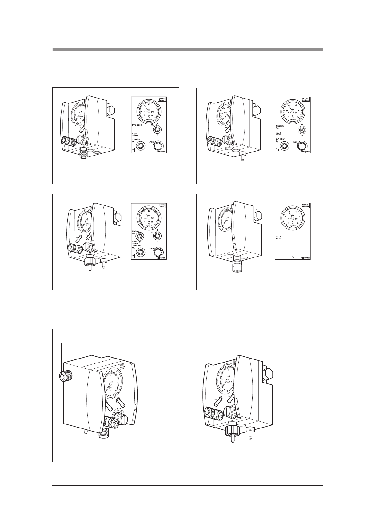
1. Overview
Module
O
1 Oxygen MODULE
1 Suction MODULE
MODUL
Interface
0
1
5
5
1
bar
0
O
2
O
2
3 Combi MODULE 4 Interface MODULE
Connections and controls (on the Combi MODULE)
5 Oxygen inlet with non-return valve 6 Flow dial 7 Oxygen outlet
1
5
5
1
0
2
O
12 External oxygen
8 ON/OFF switch13 ON/OFF switch
9 Regulator
connection
11 Inhalation
connection
10 Vacuum connection
Overview 5
Page 6
2. Description
-1,0
bar
O
2
-0,8
-0,6
-0,4
-0,2
0
0
5
10
15
l/min
O
2
0
5
10
15
l/min
O
2
2.1 Uses
Use
Increase of percentage oxygen volume in
inspiratory air
Creation of a vacuum to aspirate large
accumulations of blood, mucus, saliva and solid or
viscous food from the mouth, the pharyngonasal
cavity and the bronchial system.
Transmission of oxygen supply via couplings to
other equipment
Provision of external oxygen supply via coupling
head
The modules are not suitable for hyperbaric use
(pressure chamber).
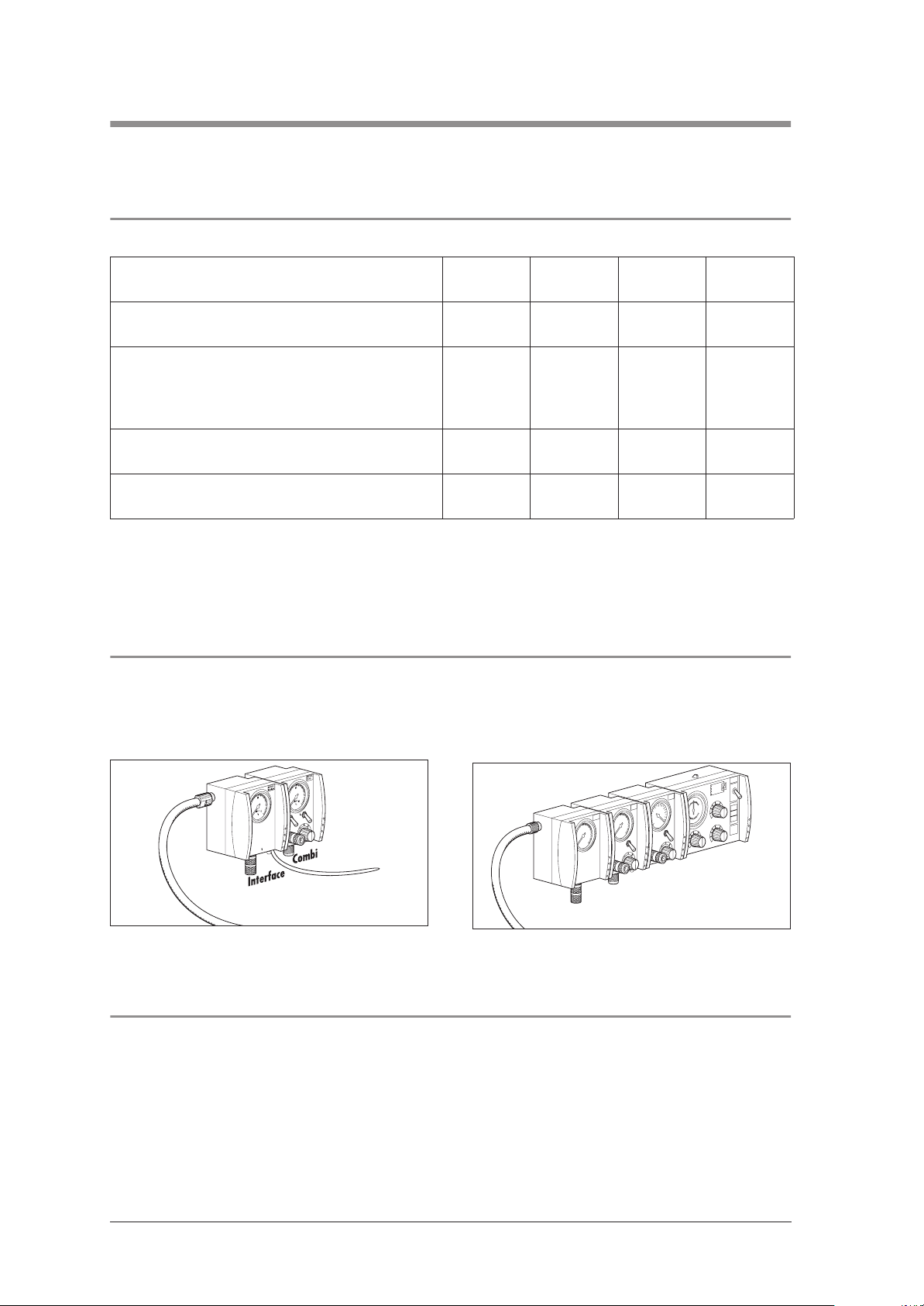
2.2 Module combinations
You can use modules either individually or in series
of up to three modules.
Oxygen
MODULE
Suction
MODULE
Combi
MODULE
Interface
MODULE
X – X –
– X X –
X X X X
X X X X
It is also possible to connect up to three modules to
the MEDUMAT ventilator.
MODUL
Suction
MODUL
Oxygen
MODUL
Interface
2
O
2
O
Oxygen
Vac
Suction
O/I
MEDUMAT
Interface
2.3 Storage
If you are not intending to use a module for a long period, we recommend the following storage precautions:
1. Clean and disinfect the module (see ”9. Hygienic preparation“ in the operating
instructions).
2. Store the module in a dry place.
6 Description
Page 7

3. Final Check
If the final check reveal defects or deviations from the specified parameters, neither the modules nor the
OMNIVAC should be used until these defects have been repaired.
We recommend you hold reserve stocks of the following items:
• washers for the tube connections
and inhalation connections WM 1145/31
• washers for connection socket WM 1145/68
3.1 Test resources required
• Blind plug G 3/8 WM 1231
• Cap WM 22204
• Set, supply test Medumat /
Modules WM 15440
• Set of test pressure gauges,
vacuum WM 15294
3.2 Preparations for final check
1. Connect module to 4.5 - 6 bar pressure supply
of the cylinder system.
2. Fully close pressure regulator (turn to left until it
meets the stop).
3.3 Entering device data
• Set, test Walther coupling,
module WM 15441
• Pressure gauge 0 – 6.3 bar, class 1.6
• Flowmeter 0 – 20 litres e.g.: Yokogawa or
EKU Vip-Ventilator / Pf 300
3. Set toggle switch to position 0.
4. If the lateral oxygen connection is not closed,
close it with cap WM 22204.
• Enter the device number and date of manufacture in the Test Record.
3.4 Check for leaks in the system
MODULE Oyxgen / Combi
1. Apply 6 bar to device and close pressure outlet.
Requirement: Pressure indication must not fall by more than 0.1 bar/min.
2. Screw blind plug onto inhalation outlet.
Final Check 7
Page 8

3. Apply approx. 4.5 bar to the input.
4. Set toggle switch to position “1”.
5. Slowly turn pressure regulator until it reads 15 l/min.
6. Close pressure supply.
Requirement: Pressure indication must not fall by more than 0.1 bar/min.
7. Close pressure regulator again and remove blind plug.
Requirement: Pressure indication must not fall by more than 0.1 bar/min.
8. Set toggle switch on device to position “0” and open pressure regulator.
Requirement: Pressure indication must not fall by more than 0.1 bar/min.
MODULE Interface
1. Apply 6 bar to device and close pressure outlet.
Requirement: Pressure indication must not fall by more than 0.1 bar/min.
2. Set toggle switch to position “1”.
Requirement: Pressure indication must not fall by more than 0.1 bar/min.
The O2 pressure indication for the module must not deviate by more than ± 0.2 bar /min.
MODULE Suction
1. Apply 6 bar to device and close pressure outlet.
Requirement: Pressure indication must not fall by more than 0.1 bar/min.
2. Set toggle switch to position “1”.
Requirement: Pressure indication must not fall by more than 0.1 bar/min.
Checking non-return valve for leaks (Oxygen, Combi and Suction module)
1. Set toggle switch to position “0”.
2. Connect pressure supply to external supply, e.g. Walther coupling (testing tube WM 15441), apply
6 bar pressure and close.
Requirement: Pressure indication must not fall by more than 0.1 bar/min.
Repairing leaks
Always keep a stock of washers for the connections available
1. Prepare a soap/water solution using nonperfumed soap.
2. Wet all the screw and hose connections with
the solution. Bubbles will form at the site of the
leak.
3. Depressurise the system (To do this, first close
the oxygen bottle. Switch on the module briefly and then switch it off again.)
4. Change the defective washers.
5. Recheck for leaks.
8 Final Check
Page 9

3.5 Checking inhalation function
MODULE Oyxgen / Combi
1. Connect inhalation outlet to a flowmeter and apply 4.5 bar pressure to the module.
2. Set flow at module to 6 l/min.
Requirement: Reading must not deviate by more than ±0.6 l/min.
3. Set flow at module to 10 l/min.
Requirement: Reading must not deviate by more than ±1.0 l/min.
4. Set flow at module to 15 l/min.
Requirement: Reading must not deviate by more than ±1.5 l/min.
5. Reduce input pressure to 2.7 bar (dynamically, at 80 l/min).
6. Switch on module and fully open pressure regulator.
Requirement: Pressure gauge reading must reach an output of at least 10 l/min.
7. Close pressure regulator and set toggle switch to position “0”.
3.6 Testing vacuum
MODULE Combi/ Suction
1. Screw the pressure supply onto the pressure inlet.
2. Reduce input pressure to 2.7 bar (dynamically, at 80 l/min).
3. Connect vacuum gauge to vacuum outlet.
4. Set toggle switch to vacuum.
Requirement: The vacuum reading must reach at least 0.35 bar.
5. Set inlet pressure to 4.5 bar.
Requirement: The vacuum reading must reach at least 0.55 bar. The device reading must not deviate
from the test gauge reading by more than ±0.05.
6. Connect vacuum connection to Rotameter.
Requirement: The suction performance must be greater than 8 l/min (flowmeter).
MODULE Suction
1. Set toggle switch to position “1”.
2. Set pressure regulator to maximum vacuum.
Requirement: See vacuum testing in section MODULE Combi/Suction.
Final Check 9
Page 10

3.7 Checking aspiration function
Necessary with the Suction MODULE and the Combi MODULE
1. Open the valve of the oxygen bottle slowly.
2. Switch on aspiration.
3. Suction MODULE:
Turn the regulator knob 9 as far right as it will
go. Remove the vacuum tube and hold vacuum connection 10 closed.
Combi MODULE:
The vacuum is locked at ≥ – 0.5 bar (at
4.5 bar O2 input pressure) and cannot be read
off the manometer 6 directly. In this case it is necessary to connect the Weinmann test manometer
WM 15294 to vacuum connection 10.
4. When the manometer 6 on the Suction
MODULE or the test manometer connected to
the Combi MODULE are showing a constant
reading, this should be not less than – 0.5 bar
at an O2 input pressure of 4.5 bar.
5. To check the OMNIVAC aspirate collection
set for leaks, replace the vacuum tube and
hold the opening of the end piece closed.
6. A reading of at least – 0.5 bar must be obtained within 30 seconds.
If this level is not reached, the connections must
be checked for leaks.
10 Final Check
Page 11

4. Servicing
Important:
Remember: a functional check must be performed after every repair.
We recommend having all maintenance work, servicing and repairs carried out either by the manufacturer
Weinmann or by a qualified technician.
4.1 Intervals
The following checks must be carried out to ensure that the modules always function correctly.
Before each use:
• Carry out a final check (see sections 3.4 to
3.7).
After each use
• Clean, disinfect or sterilise the device and its
components (see “9. Hygienic preparation” in
the operating instructions).
• Carry out a final check (see sections 3.4 to
3.7).
4.2 Servicing
The devices must be serviced every 4 years.
The following points must be covered:
At least every 6 months, if the equipment has not been used in the intervening period:
• Carry out a final check (see sections 3.2 to
3.4).
After every repair:
• Clean, disinfect or sterilise the device and its
components (see “9. Hygienic preparation” in
the operating instructions);
• Carry out a final check (see sections 3.4 to
3.7).
• Visual inspection:
– mechanical damage;
– labelling of components.
• Pressure indicator accuracy;
• Freedom from leaks;
• Oxygen delivery rate and aspiration capacity;
• Renewal of parts subject to wear / mandatory
change parts (see “7.2 Spare parts required
for servicing” on page 37);
• Functional check in accordance with Test In-
structions / Test Record WM 22248 (see “3.
Final Check” on page 7 and see “11. Repair
and inspection log” on page 45 to 48).
Servicing 11
Page 12
Every 4 years:
• Servicing of oxygen fittings (e.g. pressure reducers) by the manufacturer or by specialist personnel specifically authorised by the manufacturer.
Every 10 years:
• Repeat testing of the conventional steel or aluminium oxygen bottles by the the responsible testing organization. The test deadline can be found on the shoulder of the cylinder.
4.3 Disposal
Do not dispose of the unit with domestic waste. For proper disposal of the device and its components, please contact a certified waste disposal site for electronic goods. Ask your Environmental
Officer or local council for the address. Appliance packaging (cardboard and inserts) may be disposed of in the paper recycling bin.
5. Troubleshooting
Problem Cause of defect Elimination
Module will not switch on Module defective Arrange for repair
Oxygen bottle empty Replace oxygen bottle
Module will not function
Exceptionally high oxygen
consumption
No vacuum or vacuum too weak
or inadequate O2 flow for inhalation
Noisy inhalation/aspiration Moisture in block Replacement by Weinmann
Toggle Switch does not stay in
switch position
Pressure gauge does not reach zero
position
Module incorrectly assembled Check assembly
Tubes wrongly connected Check connections
Find and repair leak
Leak in oxygen tubes
Leak in system
Moisture in block Replacement by Weinmann
Module defective or clogged
internally.
Toggle Switch pressure plate
worn
Pressure gauge defective
(pressure hammer through open
pressure regulator 9 when switching on)
(see “3.4 Check for leaks in the
system” on page 7)
Eliminate leak
(see “3.4 Check for leaks in the
system” on page 7)
Arrange for repair
Replace toggle switch
(see “6.2.8 Replacing the toggle
switch” on page 22)
Replace the pressure gauge
(see “6.2.6 Replacing the pressure gauge” on page 20)
12 Troubleshooting
Page 13
6. Repair information and repair instructions
6.1 General
• Please observe the safety instructions in the instructions for use of the Module system.
• All handling of the device pre-supposes a precise knowledge of and compliance with the instructions for use and the service and repair
instructions.
• Please carry out only the repairs described in
these service and repair instructions. Otherwise, perfect functioning of the Modules cannot be guaranteed.
• When you replace components or individual
parts, please use original Weinmann parts
only.
6.2 Oxygen MODULE
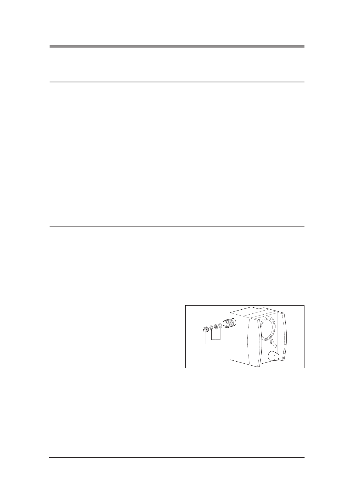
6.2.1 Replacing the sieve in the oxygen inlet
Tools required:
• Please ensure that your hands and workplace
are clean when carrying out repairs.
• Under no circumstances should you open the
screw connection in the inhalation outlet 11,
otherwise the set parameters will be altered!
• After each repair, please perform a final check
(see „3. Final Check“ on page 7).
• Note:
The item numbers used in the following text
match the item numbers in the spare parts list
on page 29 and the overview on page 4.
• Slotted screwdriver,
• Tweezers.
1. Unscrew pressure screw 49 from oxygen
inlet 5.
2. Using the tweezers, remove the sieve set 27.
3. Carefully insert a new sieve set 27 into the
oxygen inlet.
4. Screw pressure screw 49 firmly into oxygen inlet again.
2749
Repair information and repair instructions 13
Page 14
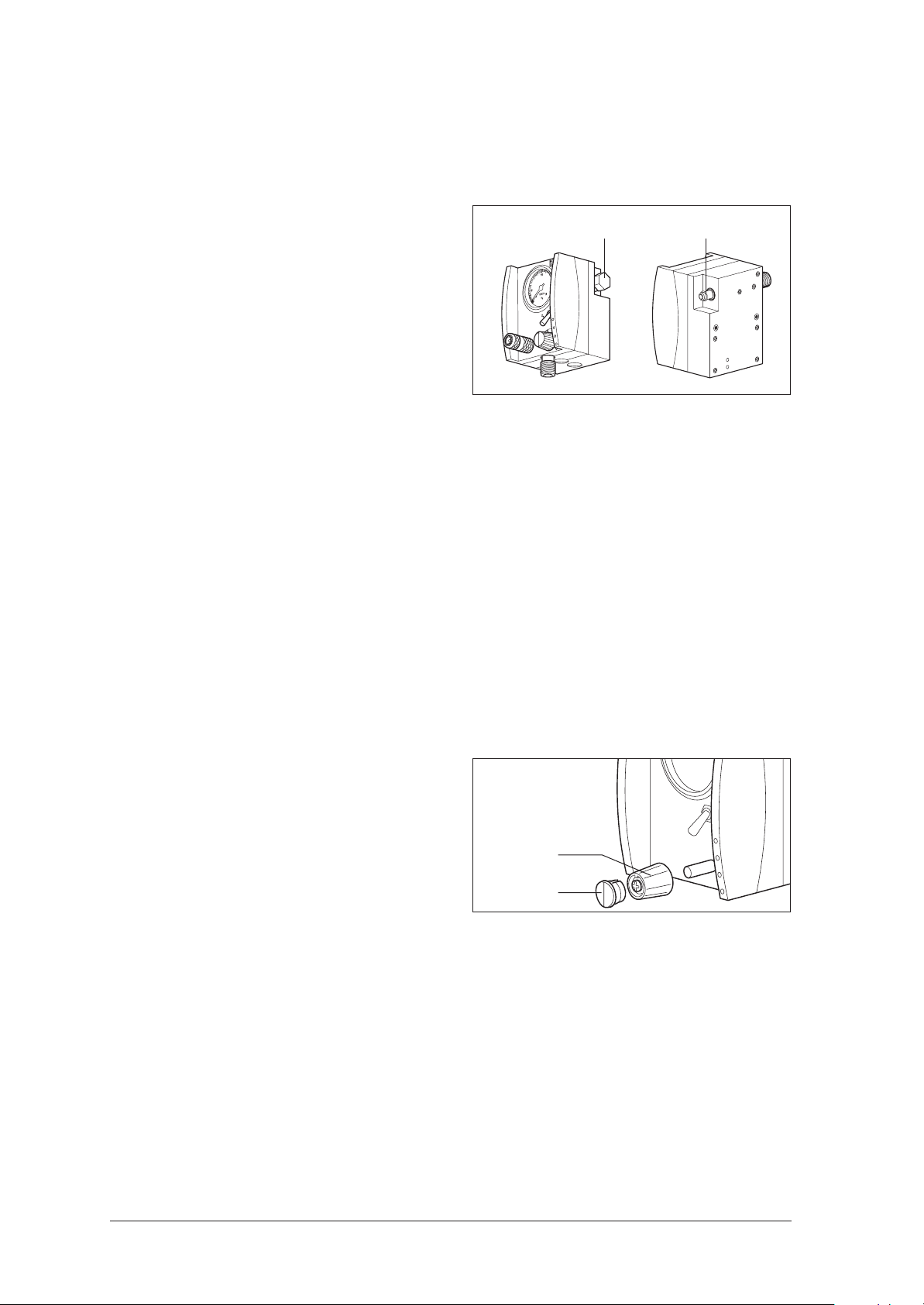
6.2.2 Replacing the O-ring in the oxygen outlet
Tools required:
• Open-ended spanner SW 16 (only necessary if the oxygen outlet 7 is sealed with the cap 47).
1. If the oxygen outlet 7 is sealed with the
cap 47, remove the cap using the open-ended
spanner (SW 16).
2. Pull the O-ring 39 from the connection.
3. Wet a new O-ring using the oxygen lubricant
Belerub (WM 14902) and push it onto the
connection.
O
4. Using open-ended spanner SW 16, gently
tighten cap 47. Do not over-tighten!
6.2.3 Dismantling the housing
Tools required:
• Crosstip screwdriver, size 1,
• Open-ended spanner SW 7,
• Open-ended spanner SW 19 (only with AGA coupling),
• Open-ended spanner SW 22,
• Guide pipes, for toggle switches (from Weinmann),
• Special locknut tool G 3/8 and special tool from Set WM 15348.
47
39
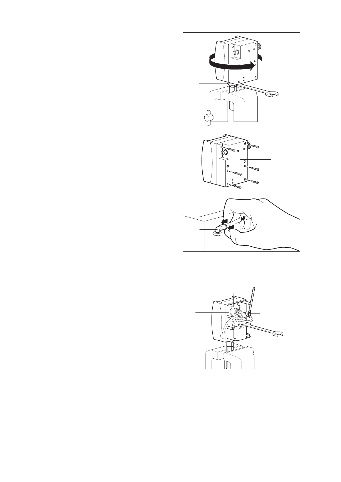
1. Twist the knob 45 as far as it will go to the left
so that you will have a reference point later on
when assembling.
2. Release the lid 46 from the knob 45.
3. Hold the knob steady using the special tool to
stop it from turning, and loosen the lock screw.
Note:
Do not unscrew the screw completely; otherwise,
the knob will be dismantled into its component
parts.
4. Pull off the knob 45.
5. If your Module is equipped with an AGA coupling, loosen it with an open-ended spanner
(SW 19).
6. Unscrew union nut at inhalation
connection 11.
7. Screw the special locknut tool onto the inhalation connection 11.
45
46
14 Repair information and repair instructions
Page 15
8. Clamp the special locknut tool in a vice with
protective jaws.
9. Tighten the nuts of the special locknut tool
against the inhalation connection 11 using an
open-ended spanner (SW 22).
10. Turn entire housing to left to undo connection 11.
If it is not possible to undo connection 11, pro-
11
ceed as described from step 11. onwards and
pull the housing apart. Clamp the special locknut tool in the vice again and use an open-ended spanner SW 22 to undo the block as
shown in the diagram.
11. Place the device on a non-slip surface and unscrew the six screws 32 from the rear panel of
the housing.
12. Pull off the housing base section 16 and fold it
away.
13. Next, remove the supply tube from the distributor block by pushing back the sleeve of the
angular bush 40 and pulling out the tube.
32
16
14. Unscrew the threaded connection for inhalation 11 at the handle of the special locknut
tool.
15. Next, lift off the upper housing section 15.
16. Using an open-ended spanner (SW 7), release the swivel screw connection 42 from the
pressure gauge 6.
17. Press the pressure gauge 6 out of the
mounting 14.
Tip:
You will find the pressure gauge easier to remove
if you dribble a small amount of spirit between
the pressure gauge and the mounting.
14
40
6
42
Repair information and repair instructions 15
Page 16
6.2.4 Assembling the housing
Tools required:
• Crosstip screwdriver, size 1,
• Open-ended spanner SW 7,
• Open-ended spanner SW 19 (only with AGA coupling),
• Open-ended spanner SW 22,
• Guide pipes, for toggle switches (from Weinmann),
• Special locknut tool G 3/8 and special tool from Set WM 15348.
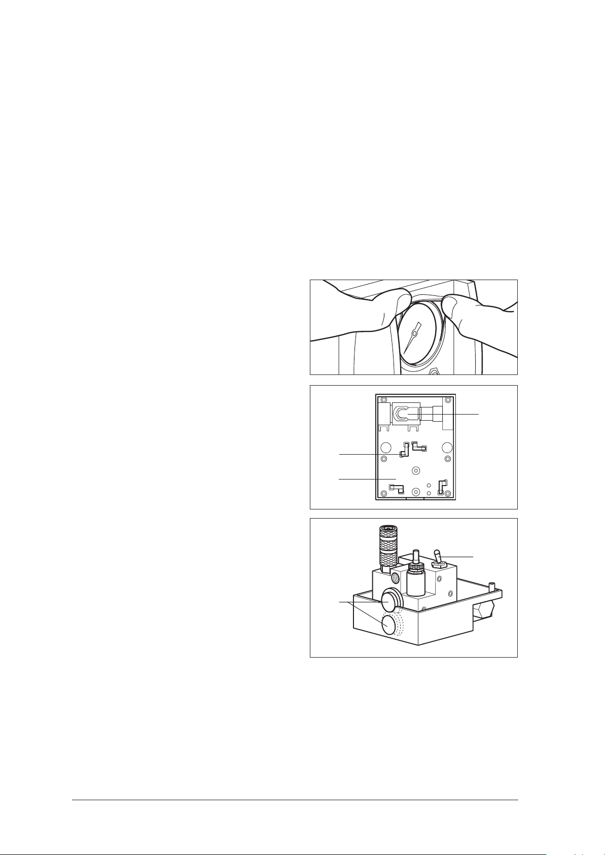
1. Wet the edge of the pressure gauge 6 with a
little spirit and press it into the mounting 14.
Observe the installation position so that the display remains clearly legible!
2. Pass the rubber bead over the pressure gauge
with your fingers.
3. Make sure that the four rubber buffers 36 in the
housing base section 16 are firmly seated (insert with a little spirit if necessary).
4. Carefully insert the two blind plugs 35 into the
holes on the underside of the housing. The flattened sides should be pointing towards the
base of the device.
5. Carefully insert the pneumatic block into the
housing base section.
6. For easier movement, disconnect the supply
tube 25 from the pnuematic block.
7. Push the supply tube into the angular bush 40
as far as it will go.
8. Rotate the angular bush 40 in the opposite direction of the oxygen inlet 5.
40
36
16
20
35
9. Push the supply tube into the bush 40 of the
pneumatic block as far as it will go.
16 Repair information and repair instructions
Page 17

10. Screw the swivel screw connection 42 onto the
pressure gauge 6 using an open-ended spanner (SW 7).
Take care to ensure the correct installation position. The tube must not protrude beyond the housing afterwards.
11. Move the toggle switch 20 to the central position and place the guide pipe over it. The
guide pipe holds the toggle switch in position,
allowing you to fit the upper housing section
more easily.
12. Carefully push the upper housing section over
the guide pipe onto the base section.
Make sure the tubes are not pinched.
Illustration of subsequent installation position
6
42
Pneumatic block
Guide pipe
20
13. Remove the guide pipe.
14. Turn the device round and screw the housing
together using the six screws 32.
15. Clean the threaded connection for
inhalation 11 and the threaded hole.
16. Connect the module to the O2 supply and
switch the toggle switch to I. Turn up the pressure control so that the threaded hole is blown
clean.
17. Wet the threaded connection 11 with Loctite
245, and screw it into the pneumatic block using the special locknut tool.
32
11
Repair information and repair instructions 17
Page 18

18. Clamp the special locknut tool in a vice.
19. Loosen the nuts of the special locknut tool using
an open-ended spanner (SW 22).
20. Remove the module from the vice and unscrew
the special locknut tool.
21. Fasten the knob 45 onto the front of the device:
– Slide the knob onto the spindle as far as it
will go.
– Twist the knob so that it is pointing to the
lowest value for "l/min".
– Hold the knob steady with the special tool
and screw it tight.
22. Check the display of the knob. At the left limit,
the white line must be pointing to the lowest
value of the arrow.
If this is not the case, loosen the screw on the
control knob, and align the knob.
23. Place the lid 46 on the control knob 45.
24. If your module is equipped with an AGA coupling, please tighten it using the open-ended
spanner (SW 19).
25. Perform a final check (see “3. Final Check” on
page 7).
11
46
45
18 Repair information and repair instructions
Page 19

6.2.5 Replacing the non-return valve in the distributor block
Tools required:
• Crosstip screwdriver, size 1,
• Open-ended spanner SW 22,
• Brass brush,
• Thread tapper M 10 x 1 for internal thread,
• Special locknut tool G 3/8, special spanner SW 20 with handle bar from Set WM 15348.
1. Unscrew the base section of the housing (see
steps 11. to 13. in chapter ”6.2.3 Dismantling
the housing“ on page 14).
2. Screw the special locknut tool onto the oxygen
inlet 5.
3. Clamp the special locknut tool in a vice.
4. Tighten the nuts of the special locknut tool
against the pressure connection using an
open-ended spanner (SW 22).
5. Place the special spanner (SW 20) onto the
distributor block.
6. Next, screw the special spanner with the housing in an counter-clockwise direction until the
oxygen inlet 5 has been loosened.
7. Open the vice, and unscrew the special locknut tool with the oxygen inlet 5 in a counterclockwise direction.
8. You can now remove the non-return valve 48.
9. Remove any adhesive residue from the thread
surfaces:
– Clean the outer thread with a brass brush.
– If necessary, re-cut the inner thread (fine
thread M 10 x 1).
10. After removing cap 47, use oxygen to blow
out any residues etc. from the distributor block.
11. Insert the new non-return valve 48.
Ensure the correct installation position: The sealing surface of the non-return valve must be pointing towards the oxygen inlet 5!
5
12. Wet the cleaned thread of the oxygen inlet 5
with Loctite 245 and screw it tight using the
special locknut tool.
13. Clamp the special locknut tool in a vice.
14. Loosen the nuts of the special locknut tool using
an open-ended spanner (SW 22).
15. Remove the Module from the vice and unscrew
the special locknut tool.
16. Join the two halves of the housing together
(see “6.2.4 Assembling the housing” on
page 16).
17. Fit cap 47 (see „6.2.2 Replacing the O-ring in
the oxygen outlet“ on page 14).
18. Perform a final check (see “3. Final Check” on
page 7).
Special spanner
SW 20
Repair information and repair instructions 19
Page 20

6.2.6 Replacing the pressure gauge
Tools required:
• Crosstip screwdriver, size 1,
• Open-ended spanner SW 7.
1. Unscrew the base section of the housing (see
steps 11. to 13. in chapter ”6.2.3 Dismantling
the housing“ on page 14).
2. Using an open-ended spanner (SW 7), release the swivel screw connection 42 from the
pressure gauge 6.
3. Press the pressure gauge 6 out of the
mounting 14.
Tip:
You will find the pressure gauge easier to remove
if you dribble a small amount of spirit between
the pressure gauge and the mounting.
4. Wet the edge of the new pressure gauge 6
with a little spirit and press it into the
mounting 14.
Important:
Observe the installation position so that the display remains clearly legible!
5. Pass the rubber bead over the pressure gauge
with your fingers.
14
6
42
Pneumatic block
6. Screw the swivel screw connection 42 to the
pressure gauge 6.
Take care to ensure the correct installation position. The tube must not protrude beyond the housing.
7. Join the two halves of the housing together
(see “6.2.4 Assembling the housing” on
page 16).
8. Perform a final check (see “3. Final Check” on
page 7).
6
42
20 Repair information and repair instructions
Page 21

6.2.7 Replacing the tubes
Tools required:
• Crosstip screwdriver, size 1,
• Bulldog end cutting nippers,
• Open-ended spanner SW 7,
• Small slotted screwdriver or flat object for bending the single-lug clips.
1. Unscrew the base section of the housing (see
steps 11. to 13. in chapter ”6.2.3 Dismantling
the housing“ on page 14).
2. Disconnect the supply tube 25 from the pneumatic block by pushing back the sleeve of the
angular bush 40 and pulling out the tube.
3. Using an open-ended spanner (SW 7), unscrew the swivel screw connection 42 from the
pressure gauge 6.
6
40
25
42
4. Open both single-lug clips 26 on the pressure
gauge tube 23:
– First, open the clips with the bulldog end cut-
ting nippers.
– Then carefully bend them open using a
small screwdriver.
5. Pull the tube from the connection on both sides.
6. Replace the pressure gauge tube 23 (150 mm
long):
– Slide a new single-lug clip 26 onto the new
pressure gauge tube 23.
– Slide the tube onto the bush 43 on the pneu-
matic block.
– Align the clip and squeeze it together using
the bulldog end cutting nippers.
– In the same way, connect the tube to the
swivel screw connection 42.
7. Push the new supply tube 25 into the angular
bush 40 on the pneumatic block as far as it will
go.
Take care to ensure the correct installation position:
The angular bush should be pointing towards the
centre of the device.
The tube runs beneath the pressure gauge tube.
6
43
23
42
26
8. Screw the swivel screw connection 42 securely
to the pressure gauge 6.
Take care to ensure the correct installation position: The tube must not protrude beyond the
housing.
9. Join the two halves of the housing together
(see “6.2.4 Assembling the housing” on
page 16).
10. Perform a final check (see “3. Final Check” on
page 7).
Repair information and repair instructions 21
Page 22

6.2.8 Replacing the toggle switch
Tools required:
• Crosstip screwdriver, size 1,
• Open-ended spanner SW 7,
• Open-ended spanner SW 17,
• Open-ended spanner SW 19 (only with AGA coupling),
• Guide pipes, for toggle switches (from Weinmann),
• Special locknut tool G 3/8 and special tool from Set WM 15348.
1. Remove the housing (see “6.2.3 Dismantling
the housing” on page 14).
2. Use an open-ended spanner (SW 17) to unscrew counter nut 51, then remove the faulty
toggle switch 20.
3. Screw in the new toggle switch 20 using the
existing counter nut 51 and the new seals.
Take care with the installation position:
The toggle switch should drop automatically into
its end position. It must not become stuck in an intermediate position.
Note:
The toggle switch will tend to drop into the upper
position.
4. Re-assemble the housing (see “6.2.4 Assembling the housing” on page 16).
5. Perform a final check (see “3. Final Check” on
page 7).
51
20
50
6.2.9 Replacing the quick-release coupling
Tools required:
• Crosstip screwdriver, size 1,
• Open-ended spanner SW 7,
• Open-ended spanner SW 14 (with Walther coupling),
• Open-ended spanner SW 19 (with AGA coupling),
• Brass brush,
• Thread tapper for internal thread G 1/8,
• Guide pipes, for toggle switches (from Weinmann),
• Special locknut tool G 3/8 and special tool from Set WM 15348.
1. Remove the housing (see “6.2.3 Dismantling
the housing” on page 14).
2. Carefully clamp the pneumatic block in a vice
with protective jaws.
22 Repair information and repair instructions
Page 23

3. Remove the coupling:
– Unscrew the Walther coupling using an
open-ended spanner (SW 14). As the
coupling is secured with Loctite 245, this
will take a little strength.
– If your Module is equipped with an AGA
coupling, unscrew it using the open-ended
spanner (SW 19).
4. Remove any adhesive residue from the thread
surfaces:
– Clean the outer thread with a brass brush.
– If necessary, re-cut the inner thread (G 1/8).
– Blow out the residue in the pneumatic block
with oxygen via the tube connection of the
main supply.
5. Join the two halves of the housing together
(see “6.2.4 Assembling the housing” on
page 16).
6. Perform a final check (see “3. Final Check” on
page 7).
50
6.2.10 Replacing O-ring of Walther coupling
1. Lift the faulty O-ring 50 out of the coupling.
2. Insert the new O-ring 50 in the coupling so that
the O-ring is properly seated in its groove.
Note:
Check that the nipple fits easily into the coupling,
and check for leaks in the external pressure supply (see “ Checking non-return valve for leaks
(Oxygen, Combi and Suction module)” on
page 8).
50
O
Repair information and repair instructions 23
Page 24

6.2.11 Replacing the pressure regulator (MODULE Oxygen: up to Device No. 1616;
MODULE
No.
Tools required:
• Crosstip screwdriver, size 1,
• Hex spanner, 2.5 mm,
• Open-ended spanner SW 7,
• Open-ended spanner SW 19 (with AGA coupling),
• Guide pipes, for toggle switches (from Weinmann),
• Special locknut tool G 3/8 and special spanner SW 14.2 from Set WM 15348,
• Special socket wrench with cross-bar for pressure regulator WM 22392.
1. Remove the housing (see “6.2.3 Dismantling
the housing” on page 14).
2. Use the special socket wrench with cross-bar
to unscrew the pressure regulator by the hexagonal nut.
3. Screw down the new pressure regulator 17 to-
gether with the seal in the pneumatic block.
4. Join the two halves of the housing together
(see “6.2.4 Assembling the housing” on
page 16).
5. Perform a final check (see “3. Final Check” on
page 7).
Combi: up to Device No. 1075; MODULE Suction: up to Device
1010)
20
6.2.12 Replacing the pressure regulator (MODULE Oxygen: from Device No. 1617;
MODULE
No.
Tools required:
• Crosstip screwdriver, size 1,
• Hex spanner, 2.5 mm,
• Open-ended spanner SW 7,
• Open-ended spanner SW 19 (with AGA coupling),
• Guide pipes, for toggle switches (from Weinmann),
• Special locknut tool G 3/8 and special spanner SW 14.2 from Set WM 15348.
1. Remove the housing (see “6.2.3 Dismantling
the housing” on page 14).
2. Unscrew and remove the lock nut for the pres-
sure regulator fixing nut.
Combi: from Device No. 1076; MODULE Suction: from Device
1011)
24 Repair information and repair instructions
Page 25

3. Place the special spanner SW 14.2 over both
nuts of the pressure regulator and unscrew
them.
4. Screw down the new pressure regulator 17 together with the seal in the pneumatic block.
5. Fit the spindle limiter screw cap 18 as follows:
– Screw the pressure regulator nuts as far
down as they will go.
– Screw in regulator spindle by hand until it
meets noticeable spring pressure; then unscrew a quarter of a turn .
– Screw the fixing nuts onto the pressure reg-
ulator housing as far as possible.
– Secure the pressure regulator fixing nuts
with the lock nut.
6. Join the two halves of the housing together
(see “6.2.4 Assembling the housing” on
page 16).
7. Perform a final check (see “3. Final Check” on
page 7).
20
51
Repair information and repair instructions 25
Page 26

6.3 Suction MODULE
6.3.1 Replacing the sieve in the oxygen inlet
See ”6.2.1 Replacing the sieve in the oxygen inlet“ on page 13.
6.3.2 Replacing the O-ring in the oxygen outlet
See ”6.2.2 Replacing the O-ring in the oxygen outlet“ on page 14.
6.3.3 Dismantling the housing
See ”6.2.3 Dismantling the housing“ on page 14.
6.3.4 Assembling the housing
See ”6.2.4 Assembling the housing“ on page 16, apart from three exceptions:
1. Re: tools required:
In addition, you will need an open-ended
spanner SW 14.
2. Re: step 10.:
The swivel screw connection must be at an angle
of approximately 45° to the horizontal.
Illustration of subsequent installation position
6
42
3. Re: step 4.:
The installation position of the two blind
plugs 35 is different:
– In the housing base section 16, the flattened
side is pointing towards the vacuum connection,
– In the upper housing section 15, the flat-
tened side is pointing towards the second
blind plug.
≈ 45°
Pneumatic block
15
35
16
26 Suction MODULE
Page 27

6.3.5 Replacing the non-return valve in the distributor block
See “6.2.5 Replacing the non-return valve in the distributor block” on page 14.
Important!
Please observe the exceptions for assembling the housing under
• ”6.3.4 Assembling the housing“ on page 26.
6.3.6 Replacing the pressure gauge
See ”6.2.6 Replacing the pressure gauge“ on page 20.
Important!
Please observe the exceptions for assembling the housing under
• ”6.3.4 Assembling the housing“ on page 26.
6.3.7 Replacing the tubes
See ”6.2.7 Replacing the tubes“ on page 21, but with three exceptions:
1. Re: step 6.:
The pressure gauge tube 24 is 80 mm long.
2. Re: steps 4. to 6.:
On the pneumatic block, the pressure gauge
tube 24 is held by an angular bush 40, not a
single-lug clip.
– To release the tube, push back the sleeve of
the angular bush 40 and pull out the tube.
– To secure the tube, push it into the angular
bush 40 as far as it will go.
40
3. Re: step 8.:
In the Suction MODULE, the pressure gauge
tube 24 has a different installation position:
The swivel screw connection 42 must be lying at
an angle of approx. 45° to the horizontal.
Important!
42
Please observe the exceptions for assembling the housing under
• ”6.3.4 Assembling the housing“ on page 26.
≈ 45°
24
40
Suction MODULE 27
Page 28

6.3.8 Replacing the toggle switch
See ”6.2.8 Replacing the toggle switch“ on page 22.
Important!
Please observe the exceptions for assembling the housing under
• ”6.3.4 Assembling the housing“ on page 26.
6.3.9 Replacing the quick-release coupling
See ”6.2.9 Replacing the quick-release coupling“ on page 22.
Important!
Please observe the exceptions for assembling the housing under
• ”6.3.4 Assembling the housing“ on page 26.
6.3.10 Replacing the pressure regulator
See ”6.2.11 Replacing the pressure regulator (MODULE Oxygen: up to Device No. 1616;
MODULE Combi: up to Device No. 1075; MODULE Suction: up to Device No. 1010)“ on page 24.
Important!
Please observe the exceptions for assembling the housing under
• ”6.3.4 Assembling the housing“ on page 26.
28 Suction MODULE
Page 29

6.4 Combi MODULE
6.4.1 Replacing the sieve in the oxygen inlet
See ”6.2.1 Replacing the sieve in the oxygen inlet“ on page 13.
6.4.2 Replacing the O-ring in the oxygen outlet
See ”6.2.2 Replacing the O-ring in the oxygen outlet“ on page 14.
6.4.3 Dismantling the housing
See ”6.2.3 Dismantling the housing“ on page 14, with one exception:
Re: Combi MODULE has two toggle switches:
6.4.4 Assembling the housing
See ”6.2.4 Assembling the housing“ on page 16, with two exceptions:
1. Re: step 4.:
Combi MODULE only requires one blind
plug 35.
2. Re: step 11.:
As Combi MODULE has two toggle switches,
please use a guide pipe over both toggle switches when mounting the upper housing
section 15.
35
15
20
Combi MODULE 29
Page 30

6.4.5 Replacing the non-return valve in the distributor block
See ”6.2.5 Replacing the non-return valve in the distributor block“ on page 19.
Important!
Please observe the exceptions for dismantling and assembling the housing under
• ”6.4.3 Dismantling the housing“ on page 29,
• ”6.4.4 Assembling the housing“ on page 29.
6.4.6 Replacing the pressure gauge
See ”6.2.6 Replacing the pressure gauge“ on page 20.
Important!
Please observe the exceptions for dismantling and assembling the housing under
• ”6.4.3 Dismantling the housing“ on page 29,
• ”6.4.4 Assembling the housing“ on page 29.
6.4.7 Replacing the tubes
See ”6.2.7 Replacing the tubes“ on page 21.
Important!
Please observe the exceptions for dismantling and assembling the housing under
• ”6.4.3 Dismantling the housing“ on page 29,
• ”6.4.4 Assembling the housing“ on page 29.
6.4.8 Replacing the toggle switch
See ”6.2.8 Replacing the toggle switch“ on page 22.
Important!
Please observe the exceptions for dismantling and assembling the housing under
• ”6.4.3 Dismantling the housing“ on page 29,
• ”6.4.4 Assembling the housing“ on page 29.
6.4.9 Replacing the quick-release coupling
See ”6.2.9 Replacing the quick-release coupling“ on page 22.
Important!
Please observe the exceptions for dismantling and assembling the housing under
• ”6.4.3 Dismantling the housing“ on page 29,
• ”6.4.4 Assembling the housing“ on page 29.
30 Combi MODULE
Page 31

6.4.10 Replacing the pressure regulator
See ”6.2.11 Replacing the pressure regulator (MODULE Oxygen: up to Device No. 1616;
MODULE Combi: up to Device No. 1075; MODULE Suction: up to Device No. 1010)“ on page 24.
Important!
Please observe the exceptions for dismantling and assembling the housing under
• ”6.4.3 Dismantling the housing“ on page 29,
• ”6.4.4 Assembling the housing“ on page 29.
Combi MODULE 31
Page 32

6.5 Interface MODULE
6.5.1 Replacing the sieve in the oxygen inlet
See ”6.2.1 Replacing the sieve in the oxygen inlet“ on page 13.
6.5.2 Replacing the O-ring in the oxygen outlet
See ”6.2.2 Replacing the O-ring in the oxygen outlet“ on page 14.
6.5.3 Dismantling the housing
See ”6.2.3 Dismantling the housing“ on page 14, with two exceptions:
1. Steps 1. to 4. do not apply, since Interface
MODULE does not have a knob.
2. Step 14. do not apply, since Interface MODULE does not have a connection for inhalation.
6.5.4 Assembling the housing
See ”6.2.4 Assembling the housing“ on page 16, with six exceptions:
1. Re: step 10.:
The swivel screw connection 42 must be lying at
an angle of approx. 45° to the horizontal.
2. Re: step 4.:
A blind plug 35 is placed into both the top side
and the underside of the device. The flattened
side of the blind plug must be pointing towards
the base of the device in both cases.
3. Step 11. does not apply, since Interface
MODULE does not have a toggle switch.
4. Re: step 12.:
During assembly of the two halves of the housing, the two pins on the upper section of the
housing must snap into the holes in the housing
base section.
5. Steps 13. to 23. do not apply, since Interface
MODULE does not have a knob.
6. As Interface MODULE does not have a toggle
switch, the upper housing section 15 may be
mounted on the housing base section 16
without guide pipes.
Illustration of subsequent installation position
42
Pneumatic block
35
≈ 45°
32 Interface MODULE
Page 33

6.5.5 Replacing the non-return valve in the distributor block
See ”6.2.5 Replacing the non-return valve in the distributor block“ on page 19.
Important!
Please observe the exceptions for dismantling and assembling the housing under
• ”6.5.3 Dismantling the housing“ on page 32,
• ”6.5.4 Assembling the housing“ on page 32.
6.5.6 Replacing the pressure gauge
See ”6.2.6 Replacing the pressure gauge“ on page 20.
Important!
Please observe the exceptions for dismantling and assembling the housing under
• ”6.5.3 Dismantling the housing“ on page 32,
• ”6.5.4 Assembling the housing“ on page 32.
6.5.7 Replacing the tubes
See ”6.2.7 Replacing the tubes“ on page 21, but with three exceptions:
1. Re: step 6.:
The pressure gauge tube 22 is 60 mm long.
2. Re: steps 4. to 6.:
On the pneumatic block, the pressure gauge
tube 22 is held by an angular bush 40, rather
than a single-lug clip.
– To release the tube, push back the sleeve of
the angular bush 40 and pull out the tube.
– To secure the tube, push it into the angular
bush 40 as far as it will go.
3. Re: step 8.:
In the Interface MODULE, the pressure gauge
tube 22 has a different installation position:
The swivel screw connection 42 must be lying at
an angle of approx. 45° to the horizontal.
40
42
≈ 45°
22
Important!
Please observe the exceptions for dismantling and assembling the housing under
• ”6.5.3 Dismantling the housing“ on page 32,
• ”6.5.4 Assembling the housing“ on page 32.
40
Interface MODULE 33
Page 34

6.5.8 Replacing the quick-release coupling
See ”6.2.9 Replacing the quick-release coupling“ on page 22.
Important!
Please observe the exceptions for dismantling and assembling the housing under
• ”6.5.3 Dismantling the housing“ on page 32,
• ”6.5.4 Assembling the housing“ on page 32.
34 Interface MODULE
Page 35

7. Spare parts
7.1 Spare parts list
Note:
The item numbers in the following table match the numbers in the text of these service and repair instructions
and the instructions for use.
Item no. Designation Order No.
5
6
14 Pressure gauge mounting WM 22223
15
16
17
Threaded connection, pre-assembled WM 22339
Pressure gauge
– 0 to 15 l/min.
– Pressure gauge 0 to 10 bar
– Pressure gauge -1.0 to 0 bar
Upper housing section with film
– Oxygen
– Suction
– Combi
– Interface
Housing base section*
consisting of housing and notice
– Oxygen/Interface Module
– Combi/Suction Module
Set of spare parts, pressure regulator
– Pressure regulator
– Sealing washer
WM 22261
WM 22262
WM 10754
WM 22355
WM 22375
WM 22365
WM 22385
WM 22358
WM 22359
WM 15183
WM 22238
WM 52380
18 Fixing nut M12 x 0.75 WM 22234
Pneumatic block**
19
20
21
22
23
24
25
26
– Oxygen, with Walther coupling, replacement
– Oxygen, with AGA coupling, replacement
– Suction, with Walther coupling, replacement
– Suction, with AGA coupling, replacement
– Combi, with Walther coupling, replacement
– Combi, with AGA coupling, replacement
Set of spare parts, toggle switch
– Oxygen/Combi
– Suction/Combi
Coupling
– DIN 13260
– AGA
– Set of spare parts, bayonet
– Walther
Set of spare parts, tubes
consisting of:
– Tube, PU 2/4 60
– Tube, PU 2/4 150
– Tube, PU 2/4 80
– Tube, PU 4/6 118
– Single-lug clip
WM 22351
WM 22354
WM 22352
WM 22357
WM 22353
WM 22356
WM 15184
WM 15193
WM 22325
WM 5944
WM 15195
WM 3798
WM 15264
Spare parts 35
Page 36

Item no. Designation Order No.
27
Sieve set
consisting of 2 seals and 1 sieve
WM 15284
Set of fixing components
consisting of:
28
29
30
31
– O-ring 8 x 4
– Raised countersunk head screw M4 x 10 DIN 966
– Protective washer Ø 4
– Raised countersunk head screw M4 x 8 DIN 966
WM 15288
Set of spare parts, screws
consisting of:
32
33
34
– Fillister-head screw KB 30 x 20, 6 off
– Raised countersunk head screw M 3 x 6 DIN 966
– Countersunk screw M 3 x 10 DIN 965
WM 15194
Set of spare parts, rubber parts
consisting of:
35
36
37
– Blind plugs
– Rubber buffer, receptacle
– O-ring 8 x 4
WM 15266
Set of spare parts, seals
38
39
consisting of:
– Seal 7 x14 x 2
– O-ring 6 x 2
WM 15283
40 Angular bush 4/6 WM 22552
41 Swivel screw connection 2/4 WM 22588
42 Swivel screw connection for pressure gauge WM 4699
43 Straight screw-in bush WM 7526
44 Seal 5 x 8 x 1 WM 1145/64
45 Knob Ø 15 WM 4897
46 Lid, matt blue, Ø 15 WM 4899
47 Cap, chrome-plated WM 22204
48 Non-return valve, assembled WM 22232
49 Pressure screw WM 1158
50 O-ring 8-1.3 WM 1145/94
51 Counter nut WM 22226
52 Fixing nut M12 x 0.75 WM 22234
Service label:
53
– 2008
– 2009
– 2010
– 2011
– 2012
– 2013
– 2014
– 2015
WM 0498
WM 0499
WM 0300
WM 0609
WM 0610
WM 0366
WM 0301
WM 0302
Distributor block, assembled WM 22263
Loctite, 245 WM 14920
Oxygen lubricant Berulub WM 14902
36 Spare parts
Page 37

* When ordering, please specify the model, device number and year of construction
** When ordering, please specify the device number
7.2 Spare parts required for servicing
Overview
Years 4 8
Service pack Suction Module WM 15559 WM 15407
Service pack Oxygen Module WM 15559 WM 15409
Service pack Combi Module WM 15559 WM 15411
Service pack Interface Module WM 15559 WM 15413
Service pack Suction, Oxygen, Combi, Interface Module 4 years
Set WM 15559
comprising:
• Sieve
• Seal 3.5x6x0.5
• Non-return valve, assembled
Service pack Suction Module 8 years
Set WM 15407
comprising:
• Sieve
• Seal 3.5x6x0.5
• Non-return valve, assembled
• 2 port / 2 position valve
• Seal 4x8x0.8
• Seal 4x8x0.5
• O-ring 6x2
• Set of tubes
Service pack Oxygen Module 8 years
Set WM 15409
comprising:
• Sieve
• Seal 3.5x6x0.5
• Non-return valve, assembled
• 2 port / 2 position valve
• Seal 4x8x0.8
• Seal 4x8x0.5
• O-ring 6x2
• Set of tubes
Spare parts 37
Page 38

Service pack Combi Module 8 years
Set WM 15411
comprising:
• Sieve
• Seal 3.5x6x0.5
• Non-return valve, assembled
• 2 port / 2 position valve
(WM 22258 MODULE Oxygen)
• 3 port / 2 position valve
(WM 22590 MODULE Oxygen)
• Seal 4x8x0.8
• Seal 4x8x0.5
• O-ring 6x2
• Set of tubes
Service pack Interface Module 8 years
Set WM 15413
comprising:
• Sieve
• Seal 3.5x6x0.5
• Non-return valve, assembled
• Set of tubes
38 Spare parts
Page 39

8. Tools and test equipment
Below is a list of all tools and test equipment used in these service and repair instructions.
The particular tools and test equipment required are outlined in each respective chapter.
Special tools can be purchased from the manufacturer Weinmann.
8.1 General tools
• Slotted screwdriver size 0.5 x 3 x 100
• Crosstip screwdriver, size 1
• Crosstip screwdriver, size 2
• Open-ended spanner SW 7
for tube connection on pressure gauge
• Open-ended spanner SW 14
for vacuum connection 10
• Open-ended spanner SW 16
for cap WM 22204 on oxygen outlet 7
• Open-ended spanner SW 17
for toggle switch
• Open-ended spanner SW 19
for connection coupling AGA
• Open-ended spanner SW 22
for special tool G 3/8
• Tweezers
for sieve set
• Bulldog end cutting nippers
for single-lug clips
• Pliers.
8.2 Special tools
The following tools are available from the manufacturers Weinmann:
• Special tool set, consisting of: WM 15348
– Special spanner SW 14.2 WM 22396
– Special socket wrench with cross-bar WM 22392
(for pressure regulator WM 15138)
– Special spanner SW 20 with handle bar WM 22391
– Special tool G 3/8 WM 22827
(for unlocking the AGA coupling
and the oxygen inlet 5
and inhalation 11 connections)
– Special tool WM 22397
(for holding the knob 9 steady)
– Guide pipes, for toggle switch. WM 22398
• Set, supply test Medumat / Modules WM 15440
• Set, supply test Modules WM 15441
• Set, test set respiration and pressure reducer flow WM 15443
Tools and test equipment 39
Page 40

8.3 Test equipment
• Set of test pressure gauges,
vacuum WM 15294
• Pressure gauge 0 – 6,3 bar, class 1.6
Type WIKA
obtainable from:
Alexander Wiegand GmbH & Co.
Alexander-Wiegand-Strasse 30
D-63911 Klingenberg am Main
Tel. +49 9372/1320
• Flowmeter 0 - 20l,
e.g. Yokogawa
or
Type EKU VIP-Ventilatortester
obtainable from:
EKU Elektronik GmbH
Feldstrasse 9a
D-56291 Leiningen
Tel.: +49 6746-1018
Fax: +49 6746-8484
www.eku-elektronik.de
40 Tools and test equipment
Page 41

9. Technical data
Oxygen MODULE Suction MODULE Combi MODULE Interface MODULE
Product category
according to
93/42/EEC
Dimensions
L x B x H in mm
Weight 0.9 kg 0.9 kg 0.95 kg 0.65 kg
Temperature range
for
– operation
– storage
Gas input medicinal oxygen
Operating pressure 2.76 bar possible, 4.5bar recommended
Minimal gas volume
required.
Pressure gas
connection
Oxygen flow
Tolerance limits
– at 0 – 3.9 l/min
– at 4 – 15 l/min
DIN ISO 10079-3
classification
100 x 125 x 90 100 x 130 x 90 100 x 172 x 90
–18 °C to +60 °C
–40 °C to +70 °C
External thread G3/8; NIST adapter available on request
variable from
0 to 15 l/min
±15%
±10%
IIa
≥ 80 l/min O
variable from
0 to 15 l/min
±15%
±10%
medium vacuum
2
Technical data 41
Page 42

9.1 External oxygen flow volume
The following flow volumes apply when oxygen is supplied to other equipment.
Interface MODULE
Oxygen input External oxygen flow volume
2.7 bar dynamic operating
pressure at 80 l/min
from Weinmann pressure reducer
O
2
WM 1102/106
not less than 70 l/min
not less than 100 l/min
from Weinmann pressure
reducer WM 30301
More than one module
When several modules are connected in series,
the flow volume decreases with the module’s distance from the oxygen input. This is due to the high
flow resistance arising when the oxygen passes
through more than one module.
2.7 bar dynamic operating
pressure at 80 l/min
from Weinmann pressure reducer
WM 1102/106
from Weinmann pressure reducer
WM 30301
The figures are based on the assumption that oxygen is being supplied only from one module at a
time.
Oxygen input
not less than 90 l/min
External oxygen flow volume
A B C
not less
than
76 l/min
not less
than
100 l/min
not less
than
91 l/min
not less
than
73 l/min
not less
than
95 l/min
not less
than
88 l/min
not less
than
70 l/min
not less
than
90 l/min
not less
than
85 l/min
9.2 Oxygen flow volume from inhalation connection
Input pressure 2.7 bar 3.0 bar 3.5 bar 6.0 bar
Maximal oxygen flow volume 11 l/min 12 l/min 15 l/min 15 l/min
Tolerance ±10%
42 Technical data
Page 43

9.3 Aspiration efficiency
Maximal suction
The maximal suction exerted by the Combi and Suction MODULES depends on the input pressure of the
oxygen supply. The data below are valid for a 2 litre aspirate bottle.
Input pressure p2 Max. vacuum Maximal suction Oxygen consumption
2.7 bar - 0.40 bar 8.4 l/min 9.3 l/min
3.0 bar - 0.44 bar 8.6 l/min 10.1 l/min
3.5 bar - 0.53 bar 8.8 l/min 11.4 l/min
4.0 bar - 0.58 bar 9.0 l/min 12.2 l/min
4.5 bar - 0.60 bar 9.0 l/min 14.0 l/min
5.0 bar - 0.60 bar 9.0 l/min 15.0 l/min
5.5 bar - 0.60 bar 8.7 l/min 17.0 l/min
6.0 bar - 0.60 bar 8.5 l/min 19.0 l/min
Tolerance limits ±10%. If a bacterial filter is used,
the aspiration efficiency will diminish by between
1 and 3 l/min, depending on the atmospheric
humidity.
Aspiration efficiency of Suction MODULE
The suction exerted by the Suction MODULE varies according to the degree of vacuum selected at any given
time. The data below are valid for a 2 litre aspirate bottle.
Selected vacuum Suction Oxygen consumption
- 0.2 bar 5.3 l/min 6.5 l/min 2.7 – 6 bar
- 0.3 bar 6.5 l/min 7.7 l/min 2.7 – 6 bar
- 0.4 bar 8.4 l/min 9.3 l/min 2.7 – 6 bar
- 0.5 bar 8.3 l/min 10.5 l/min 3.5 – 6 bar
- 0.6 bar 9.0 l/min 14.0 l/min 4.5 bar
Tolerance limits ±10%. If a bacterial filter is used,
the aspiration efficiency will diminish by between
1 and 3 l/min.
Required input
pressure p2
Technical data 43
Page 44

10. Technical Changes
Technical change From Device No. Date
With screw cap WM 20522 1618 17.08.98
White cap 2396 15.01.99
Counter nut V2A WM 22226 2896 07.05.99
New screw cap WM 22234 4096 10.01.00
Reinforcement for lower part of housing 14101 17.05.04
44 Technical Changes
Page 45

11. Repair and inspection log
11.1 Oxygen MODULE
Date Signature
with MODULE service instructions
Service performed in accordance
Company
_____________ __________________
Company
Measures / Comments
Date Signature
_____________ __________________
Company
Date Signature
_____________ __________________
Company
Date Signature
_____________ __________________
22525 Hamburg
Device master data Inspections and repairs carried out in accordance with the service instructions
Manufacturer: Weinmann GmbH + Co.
Device model: Oxygen MODULE
❐ WM 22200 with Walther coupling
❐ WM 22240 with AGA coupling
Serial no.: _________________________
Date of manufacture: ________________
Before each use ____________________
Functional check:
After each use _____________________
Repair and inspection log 45
Every 6 months ____________________
After every repair __________________
Page 46

11.2 Suction MODULE
Date Signature
with MODULE service instructions
Service performed in accordance
Company
_____________ __________________
Company
Measures / Comments
Date Signature
_____________ __________________
Company
Date Signature
_____________ __________________
Company
Date Signature
_____________ __________________
22525 Hamburg
Device master data Inspections and repairs carried out in accordance with the service instructions
Manufacturer: Weinmann GmbH + Co.
46 Repair and inspection log
Device model: Suction MODULE
❐ WM 22220 with Walther coupling
❐ WM 22260 with AGA coupling
Serial no.: _________________________
Date of manufacture: ________________
Before each use ____________________
Functional check:
After each use _____________________
Every 6 months ____________________
After every repair __________________
Page 47

11.3 Combi MODULE
Date Signature
with MODULE service instructions
Service performed in accordance
Company
_____________ __________________
Company
Measures / Comments
Date Signature
_____________ __________________
Company
Date Signature
_____________ __________________
Company
Date Signature
_____________ __________________
22525 Hamburg
Device master data Inspections and repairs carried out in accordance with the service instructions
Manufacturer: Weinmann GmbH + Co.
Device model: Combi MODULE
❐ WM 22210 with Walther coupling
❐ WM 22250 with AGA coupling
Serial no.: _________________________
Date of manufacture: ________________
Before each use ____________________
Functional check:
After each use _____________________
Repair and inspection log 47
Every 6 months ____________________
After every repair __________________
Page 48

11.4 Interface MODULE
Date Signature
with MODULE service instructions
Service performed in accordance
Company
_____________ __________________
Company
Measures / Comments
Date Signature
_____________ __________________
Company
Date Signature
_____________ __________________
Company
Date Signature
_____________ __________________
22525 Hamburg
Device master data Inspections and repairs carried out in accordance with the service instructions
Manufacturer: Weinmann GmbH + Co.
48 Repair and inspection log
Device model: Interface MODULE
❐ WM 22290 with Walther coupling
❐ WM 22280 with AGA coupling
❐ WM 22270 with Shraeder-Valve coupling
❐ WM 22230 with Dräger coupling
Serial no.: _________________________
Date of manufacture: ________________
Before each use ____________________
Functional check:
After each use _____________________
Every 6 months ____________________
After every repair __________________
Page 49

Page 50

Page 51

Page 52

For decades Weinmann has been
developing, producing and marketing
medical devices for markets around
the world. In cooperation with our
partners we design economic health
systems for diagnosis and therapy in
Sleep Medicine, Home Mechanical
Ventilation, Oxygen Medicine
and Emergency Medicine.
Weinmann
Geräte für Medizin GmbH + Co. KG
P.O. Box 540268 · D-22502 Hamburg
Phone +49/40/5 47 02-0
Fax +49/40/5 47 02-461
E-mail int.sales@weinmann.de
Internet www.weinmann.de
WM 16289c · 10/07
 Loading...