

Page 1

Ventilation device
Description of device and instructions for use
for devices from serial number 20,000
VENTIlogic LS
VENTIlogic plus
Page 2

Contents
2 Contents
EN
1. Overview . . . . . . . . . . . . . . . . . . . . . 4
1.1 Special markings on the device. . . . .12
1.2 Safety information in the instructions
for use . . . . . . . . . . . . . . . . . . . . . . .22
2. Description of device . . . . . . . . . . 23
2.1 Intended use . . . . . . . . . . . . . . . . . .23
2.2 Owner/operator and user
qualification . . . . . . . . . . . . . . . . . . .24
2.3 Description of function. . . . . . . . . . .24
3. Safety instructions . . . . . . . . . . . . 29
3.1 Safety information . . . . . . . . . . . . . .29
3.2 Contraindications . . . . . . . . . . . . . . .36
3.3 Side effects . . . . . . . . . . . . . . . . . . .37
4. Set up device . . . . . . . . . . . . . . . . . 38
4.1 Set up and connect the device . . . . .38
4.2 Patient/ventilator interfaces . . . . . . .39
4.3 Connect valve ventilation . . . . . . . . .39
4.4 Connect leakage ventilation . . . . . . .41
4.5 Connect humidifier . . . . . . . . . . . . .43
4.6 Connect bacteria filter . . . . . . . . . . .43
4.7 Therapy with oxygen supply . . . . . . .45
4.8 Operation in the event of a power
failure . . . . . . . . . . . . . . . . . . . . . . .48
5. Operation . . . . . . . . . . . . . . . . . . . . 49
5.1 Controls . . . . . . . . . . . . . . . . . . . . . .49
5.2 Start up the device . . . . . . . . . . . . . .51
5.3 Handling batteries . . . . . . . . . . . . . .53
5.4 Activate/deactivate Auto switch-on
(only leakage ventilation) . . . . . . . . .55
5.5 Alarm list . . . . . . . . . . . . . . . . . . . . .56
5.6 Adjust brightness . . . . . . . . . . . . . . .56
5.7 LIAM info . . . . . . . . . . . . . . . . . . . . .57
5.8 Overview . . . . . . . . . . . . . . . . . . . . .58
5.9 Humidifier for patient circuits with
patient valve. . . . . . . . . . . . . . . . . . .58
5.10 LIAM (insufflation) . . . . . . . . . . . . . .58
5.11 Select a program . . . . . . . . . . . . . . .61
5.12 After use . . . . . . . . . . . . . . . . . . . . .62
5.13 Travel with the therapy device . . . . .64
6. Hygiene treatment . . . . . . . . . . . . 67
6.1 Intervals . . . . . . . . . . . . . . . . . . . . . .67
6.2 Clean leakage ventilation . . . . . . . . .68
6.3 Clean the housing. . . . . . . . . . . . . . 70
6.4 Clean coarse dust filter/change fine
filter . . . . . . . . . . . . . . . . . . . . . . . . 70
6.5 Clean the fan filter . . . . . . . . . . . . . 71
6.6 Clean the accessories . . . . . . . . . . . 71
6.7 Clean the SpO
2
module . . . . . . . . . . 71
6.8 Disinfect, sterilize . . . . . . . . . . . . . . 71
6.9 Change in patients . . . . . . . . . . . . . 73
7. Function check . . . . . . . . . . . . . . . . 74
7.1 Intervals . . . . . . . . . . . . . . . . . . . . . 74
7.2 Method . . . . . . . . . . . . . . . . . . . . . 74
7.3 Calibrate oxygen sensor
(only valve ventilation). . . . . . . . . . . 78
7.4 Energy supply . . . . . . . . . . . . . . . . . 80
8. Troubleshooting . . . . . . . . . . . . . . . 81
8.1 Faults . . . . . . . . . . . . . . . . . . . . . . . 81
8.2 Alarms . . . . . . . . . . . . . . . . . . . . . . 83
9. Maintenance and safety checks . . 95
9.1 Intervals . . . . . . . . . . . . . . . . . . . . . 95
9.2 Batteries . . . . . . . . . . . . . . . . . . . . . 96
9.3 Change filter. . . . . . . . . . . . . . . . . . 97
9.4 Change pressure-measurement
tube (only leakage ventilation) . . . 100
9.5 Safety check . . . . . . . . . . . . . . . . . 100
9.6 Disposal . . . . . . . . . . . . . . . . . . . . 101
10. Scope of supply . . . . . . . . . . . . . . . 103
10.1 Standard scope of supply . . . . . . . 103
10.2 Accessories and spare parts. . . . . . 107
11. Technical data . . . . . . . . . . . . . . . . 108
11.1 Therapy device . . . . . . . . . . . . . . . 108
11.2 System resistances . . . . . . . . . . . . 112
11.3 Bacteria filter WM 24148 and
WM 27591 . . . . . . . . . . . . . . . . . . 112
11.4 Oxygen sensor . . . . . . . . . . . . . . . 113
11.5 SpO
2
module . . . . . . . . . . . . . . . . . 114
11.6 Analog box with therapy device . . 115
11.7 Pneumatic diagrams . . . . . . . . . . . 116
11.8 Safety distances . . . . . . . . . . . . . . 119
11.9 Emission of electromagnetic
interference . . . . . . . . . . . . . . . . . 120
11.10Electromagnetic interference
immunity . . . . . . . . . . . . . . . . . . . 121
Page 3

3
EN
11.11Electromagnetic interference
immunity for life-supporting medical
electrical devices and medical
electrical systems. . . . . . . . . . . . . . 123
11.12Electromagnetic interference
immunity for NON-LIFE-SUPPORTING
medical electrical devices or
medical electrical systems . . . . . . . 124
12. Warranty . . . . . . . . . . . . . . . . . . . . 125
13. Declaration of conformity . . . . . 125
Page 4

4 Overview
EN
English
1. Overview
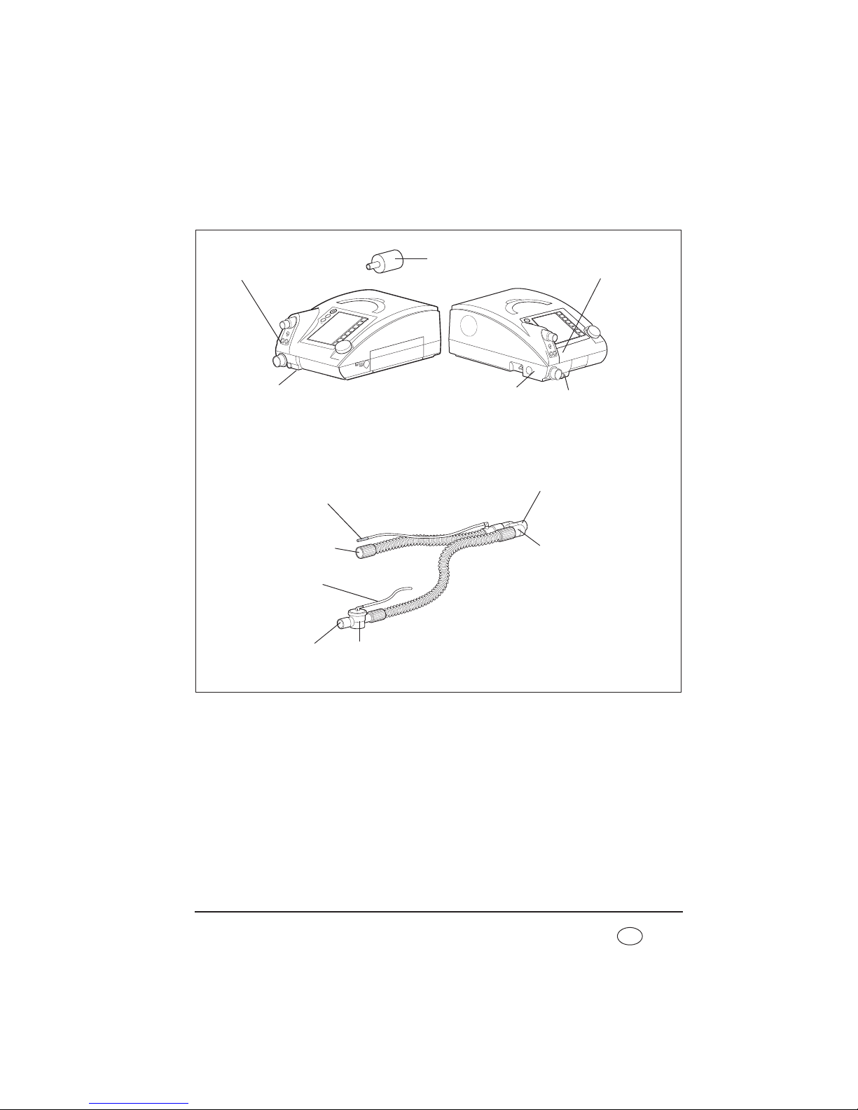
Therapy device, general
5 Power cord
6 Compartment for
replaceable battery
available as an option
3 Control panel
and displays
4 Handle
1 Device outlet port
16 Housing fan
8 Card reader
9 Serial ports
13 Power connection
15 Oxygen
connection
11 Remote alarm
connection
14 Device ID plate
10 Filter
compartment lid,
air inlet
12 Cable-securing clip
2 O2 coupling
7 Replaceable battery
(optional)
Page 5

Overview 5
EN
Key
1 Device outlet port
The respiratory air flows to the patient from here
via the patient circuit and the patient/ventilator
interface.
2 O2 coupling
Serves as an adapter for connecting the oxygen
source to the therapy device.
3 Control panel and displays
For controlling and monitoring the therapy device
and connected accessories.
4 Handle
For transporting the device.
5 Power cord
For connecting the therapy device to the power
supply.
6 Compartment for replaceable
battery available as an option
For connecting a replaceable battery, available as
an option. If you are not using a replaceable
battery, the compartment is sealed with a panel.
7 Replaceable battery (optional)
Available as an accessory. For mobile power
supply to the therapy device.
8 Card reader
Slot for a Weinmann memory card. Therapy data
are stored on the memory card which the doctor
can call up.
9 Serial ports
For connecting devices for displaying and
evaluating therapy data.
10 Filter compartment lid, air inlet
For covering and securely positioning the coarse
dust and fine filters.
11 Remote alarm connection
For connecting the hospital's internal nurse call
system or the VENTIremote alarm remote alarm
case for use outside the hospital.
12 Cable-securing clip
Prevents the device being disconnected from the
power supply inadvertently.
13 Power connection
This is where the power cord is connected to the
device.
14 Device ID plate
Provides information about the device, such as
serial number and year of manufacture, for
example.
15 Oxygen connection
For connecting the oxygen supply if oxygen
supply has been prescribed.
16 Housing fan
Protects the device from overheating.
Page 6

6 Overview
EN
Therapy device with leakage ventilation
Key
17 Patient circuit
The air flows to the patient/ventilator interface
through the patient circuit. The patient circuit
consists of creased hose, pressure measuring tube
and adapter.
18 Adapter
For connecting the patient circuit to the device
outlet port.
19 Pressure measuring tube
For measuring therapy pressure.
20 Creased tube
Delivers respiratory air to the patient.
21 Sealing plug (2x)
For sealing off the pressure measuring tube
during cleaning (only with leakage ventilation).
22 Drying adapter
Required to dry the patient circuit with the aid of
the therapy device and for the function check.
23 Exhalation system
Carbon dioxide-enriched exhaled air escapes here
during therapy.
24 Connection for O2 sensor
For connecting an oxygen sensor which can be
used to measure oxygen concentration in
respiratory air.
17 Patient circuit
22 Drying adapter
21 Sealing plug (2x)
19 Pressure
measuring tube
18 Adapter
23 Exhalation
system
24 Connection for O2 sensor
20 Creased tube
17 Patient circuit
Page 7

Overview 7
EN
Therapy device, single patient circuit with patient valve
Key
25 Connection for O2 sensor
For connecting an oxygen sensor which can be
used to measure oxygen concentration in
respiratory air (only with patient circuits with a
patient valve).
26 Connection for pressure measuring
tube (marked blue)
For connecting the pressure measuring tube to
the device.
27 Test adapter
Required for the function check of the therapy
device.
28 Connection for valve control tube
For connecting the valve control tube to the
device.
29 Single patient circuit
Delivers respiratory air to the patient.
26 Connection for pressure
measuring tube (marked
blue)
29 Single patient circuit
30 Pressure-
measurement
tube (marked
blue)
31 Valve control
tube
32 Patient valve
28 Connection for
valve control tube
33 Connection for
patient
34 Connection for
device outlet port
27 Test adapter
25 Connection for O2 sensor
Page 8

8 Overview
EN
30 Pressure-measurement tube (marked
blue)
For measuring therapy pressure.
31 Valve control tube
For controlling (opening and closing) the patient
valve.
32 Patient valve
For routing the patient's exhaled air out of the
patient circuit.
33 Connection for patient
This is where the patient/ventilator interface is
connected.
34 Connection for device outlet port
This is where the patient circuit is connected to
the device outlet port of the therapy device.
Page 9
Overview 9
EN
Therapy device, double patient circuit with patient valve
(VENTIlogic LS only)
35 Connection for O2 sensor
For connecting an oxygen sensor which can be
used to measure oxygen concentration in
respiratory air (only with patient circuits with a
patient valve).
36 Connection for pressure-
measurement tube (marked blue)
For connecting the pressure measuring tube to
the device.
37 Test adapter
Required for the function check of the therapy
device.
38 Connection for valve control tube
For connecting the valve control tube to the
device.
39 Device connection for patient valve
For connecting the patient valve to the device
inlet port of the therapy device.
39 Device connection for
patient valve
36 Connection for pressure-
measurement tube
(marked blue)
41 Double patient circuit
43 Y-adapter
44 Patient valve
46 Valve control
tube
48 Pressure-
measurement tube
(marked blue)
38 Connection for
valve control tube
40 Opening for
exhaled air
42 Connection
for patient
45 Connection for
device inlet port
47 Connection for
device outlet port
37 Test adapter
35 Connection for O2 sensor
Page 10

10 Overview
EN
40 Opening for exhaled air
This is where the patient's exhaled air is routed
out of the device.
41 Double patient circuit
Delivers respiratory air to the patient and from the
patient back to the device.
42 Connection for patient
This is where the patient/ventilator interface is
connected.
43 Y-adapter
When the double patient circuit is used, this
brings the inspiration and exhalation tubes
together and serves as an adapter for connection
to the patient/ventilator interface.
44 Patient valve
For routing the patient's exhaled air out of the
patient circuit.
45 Connection for device inlet port
This is where the patient circuit is connected to
the device outlet port of the therapy device.
46 Valve control tube
For controlling (opening and closing) the patient
valve.
47 Connection for device outlet port
This is where the patient circuit is connected to
the device inlet port for the patient valve (only
with double patient circuit with patient valve).
48 Pressure-measurement tube (marked
blue)
For measuring therapy pressure.
Page 11

Overview 11
EN
Accessories
Key
49 Replaceable battery WM 27880
Available as an accessory, for mobile power
supply to the therapy device.
50 Carrying bag WM 27976
For mobile use of the therapy device.
51 Bacteria filter WM 24148 (only
leakage ventilation) and 52 Bacteria
filter WM 27591 (only valve ventilation)
For protecting the device from contamination, in
particular when the device is used by several
patients (patient change).
53 Set, O2 sensor WM 15732
For measuring oxygen concentration at the device
outlet port.
54 Protective bag WM 27106
For protecting the therapy device during
transport.
50 Carrying bag
WM 27976
54 Protective bag
WM 27106
53 Set, O2 sensor WM 15732
52 Bacteria filter
WM 27591
(only valve ventilation)
51 Bacteria filter WM 24148
(only leakage ventilation)
49 Replaceable battery WM 27880
Page 12

12 Overview
EN
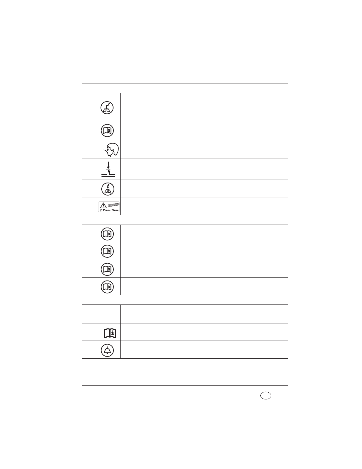
1.1 Special markings on the device
Left-hand side
1
Oxygen connection: maximum supply rate: 15 l/min at < 1000 hPa
2
VENTIlogic LS:
Opening for exhaled air when operated with double patient circuit with patient
valve; do not seal opening or block in any other way.
VENTIlogic plus:
Opening is not used with VENTIlogic plus.
7
6
5
4
3
2
1
12
11
10
9
15
18
14
16 17
8
13
Page 13
Overview 13
EN
Front
3
VENTIlogic LS:
Connection for patient's exhaled air with double patient circuit with patient valve.
VENTIlogic plus:
Opening is not used with VENTIlogic plus.
4
Jack: electrical connection for oxygen sensor; max. 100 mV DC
5
Connection: pressure measuring tube (marked blue). Therapy pressure 0 - 50 hPa
(only for patient circuit with patient valve)
6
Connection: control tube for patient valve 0 - 50 hPa (only patient circuit with
patient valve)
7
Device outlet port: outlet for exhaled air at 0 - 45 hPa with patient circuits with
patient valve, 0 - 40 hPa with leakage ventilation
8
Device outlet port: only patient circuits with a diameter of Ø 15 mm - 22 mm are
permitted.
Right-hand side
9
Connection for optional attachments, e.g. Analog box D/A;
max. current delivery at 5 V: 50 mA
10
Connection for specialist staff to set therapy parameters using VENTIviews; max.
current delivery at 12 V: 50 mA
11
SD card slot
12
Replaceable battery
Rear
13
Connector for power supply input 115/230 V AC; 50/60 Hz
14
Follow instructions for use
15
Connection for remote alarm: connection for nurse call system and VENTIremote
alarm remote alarm case. Breaking capacity: 60 V DC/2 A; 42 V AC/2 A
P
~
Page 14

14 Overview
EN
16
Servicing label: indicates when the next service is due
17
Safety check label: (in Germany only) marks when the next safety check as per §6
of the German law relating to users of medical devices is required
18
Device inlet port: inlet port for ambient air at room temperature
Device ID plate (rear)
Type BF application part
Protection class II, protective insulation
Year of manufacture
Do not dispose of device in domestic waste!
SN Serial number
100 V/230 V ~,
50-60 Hz
Electrical rating
CE 0197 symbol: Confirms that the product conforms to the applicable European
directives
Protect device from wet
STK
Page 15
Overview 15
EN
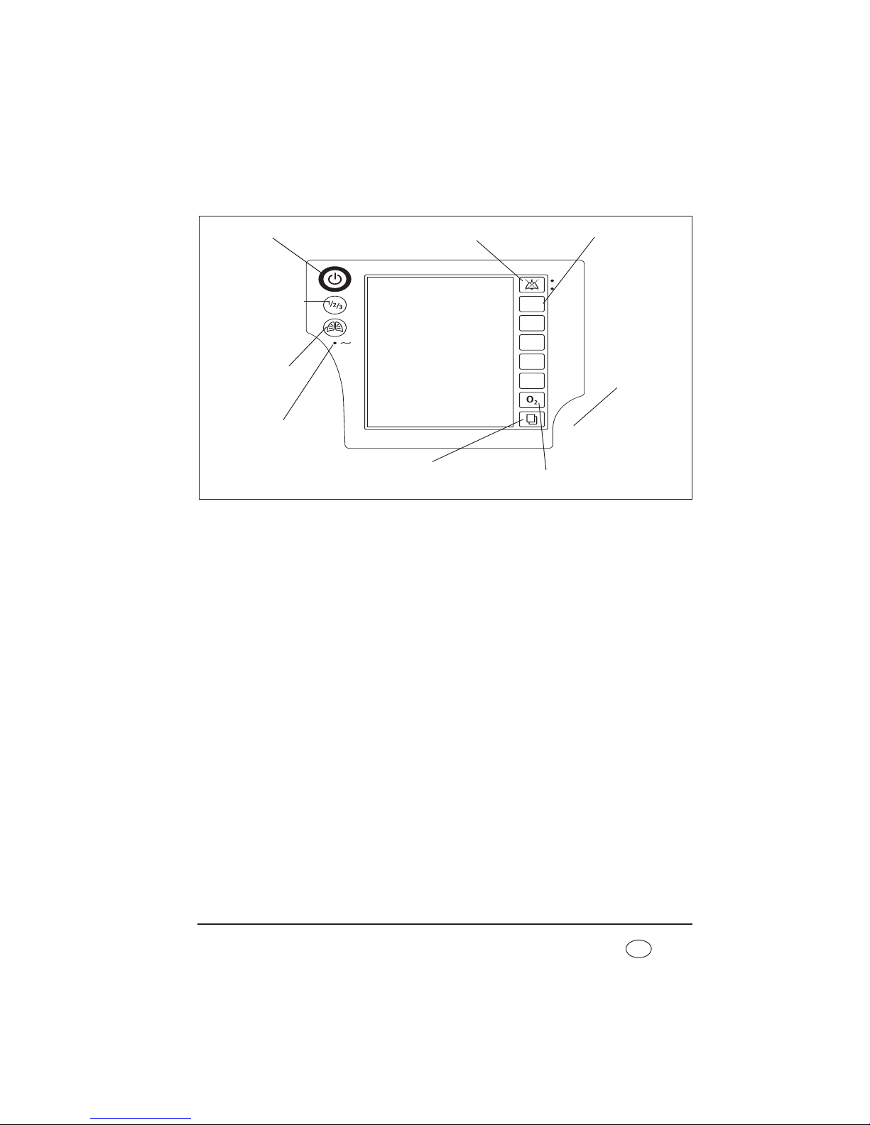
Control panel
Key
1 On/Off key
For switching the therapy device on and off.
2 Alarm acknowledgement key
The alarm acknowledgement key is for the
temporary muting of alarms. The LED displays
alarms visually.
3 Operating keys
For quick-setting by a doctor; deactivated in
patient mode.
4 Dial
Central control of the therapy device, for
navigating in the menu.
5 O2 key
Starts calibration of the O2 sensor. Has other
functions in the Clinical menu.
6 Menu key
For switching from the default display to the
menu and vice versa.
7 LED for power supply
The green LED comes on when there is a power
supply.
8 LIAM (insufflation)
For triggering a coughing episode or ventilating a
sigh.
9 Program key
For switching to one of the three pre-configured
programs manually.
Vt
PEEP
IPAP
F
I : E
8 LIAM (insufflation)
1 On/Off key
2 Alarm acknowledgement
key
3 Operating keys
7 LED for power supply
4 Dial
5 O2 key
6 Menu key
9 Program key
Page 16

16 Overview
EN
Default display during therapy
Key
1 Active ventilation mode
The active ventilation mode is displayed at this
point in the status line.
2 Status line
This is where device status information (such as
alarm state display, filter change or servicing due)
is displayed.
3 Alarm display
If an alarm has been muted, it is then shown in
the status line for 120 seconds.
4 Active program
Indicates the ventilation program currently active.
5 Battery charge status of internal
battery
Displays the charge status of the internal battery.
When the battery is charging, the segments are
shown consecutively.
6 Battery charge status of replaceable
battery (optional)
Displays the charge status of the replaceable battery
available as an option. If the battery is being
charged, the segments are shown in succession.
7 Memory card symbol
Appears if a memory card is present and there is
data saved on the memory card.
8 Respiratory phase change display
Indicates whether the current respiratory phase
change is spontaneous or mandatory
(spontaneous: S, mandatory: T); the display
changes from left (inspiration) to right
(exhalation) depending on respiratory phase;
mandatory exhalation is shown here.
Also indicates whether the trigger for inspiration
is blocked due to an activated trigger lockout time
at the start of expiration ( ).
1 Active ventilation
mode
10 Bar chart for pressure display
9 Access to patient
menu
8 Respiratory phase
change display
12 Ventilation
parameters
13 Patient circuit
2 Status line
7 Memory card symbol
11 Oxygen
concentration
(optional)
6 Battery charge status of
replaceable battery (optional)
5 Battery charge status of internal
battery
3 Alarm display
4 Active program
Page 17

Overview 17
EN
9 Access to patient menu
Use the key adjacent to this menu item to switch
to the patient menu and back to the default
display.
10 Bar chart for pressure display
For the graphical display of therapy pressure.
11 Oxygen concentration (optional)
Gives oxygen concentration in respiratory air in
percent.
12 Ventilation parameters
The relevant current ventilation parameters are
displayed depending on the active mode.
13 Patient circuit
The relevant text to suit the set patient circuit
appears in the status line.
Page 18

18 Overview
EN
Symbols used in the display
Symbol Significance
Status line:
Filter change required
Servicing required
Acoustic signal of alarms muted for 120 seconds
All physiological alarms deactivated (exception for
VENTIlogic LS: In VCV and
aVCV modes, the Pressure
high
and Pressure
low
alarms cannot be
deactivated)
Blower off (standby mode)
Battery display green (2-5 segments): battery capacity over 25 %
Battery display orange: battery capacity below 25 %
Battery display red: battery capacity below 10 %
Segments are displayed in succession: device operated by power supply, battery
charging
Battery not present
Battery not ready for use:
– battery defective or
– battery too cold or
– battery too hot
Battery not recognized as a Weinmann battery. Replace battery.
Device in internal battery mode.
Measured values are written to the SD card
Page 19
Overview 19
EN
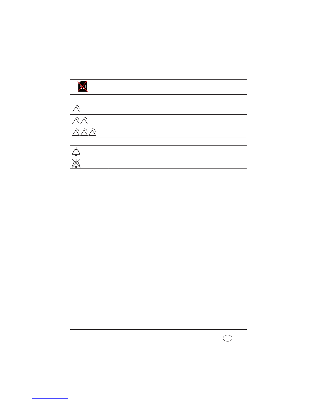
SD card is write-protected or defective. No data can be recorded.
Alarm window:
Low-priority alarm triggered
Medium-priority alarm triggered
High-priority alarm triggered
Main window:
Plateau signal switched on
Plateau signal switched off
Symbol Significance
Page 20

20 Overview
EN
Abbreviations used in the display
Symbol Significance
Status line:
S
S mode active
ST
ST mode active
T
T mode active
CPAP
CPAP mode active
PCV
PCV mode active
PSV
PSV mode active
aPCV
aPCV mode active
VCV
VCV mode active (VENTIlogic LS only)
aVCV
aVCV mode active (VENTIlogic LS only)
SIMV
SIMV mode active
MPVp MPVp mode active
MPVv MPVv mode active
+V
Volume compensation activated (after mode: e.g PCV+V)
+A
AirTrapControl activated (after mode: e.g. ST +A)
+LIAM
LIAM enabled: displayed under the current mode, e.g.:
PCV
+LIAM
LIAM
LIAM (Lung Insufflation Assist Maneuver) active
Prog.
Active ventilation program
Main window (Monitor):
IPAP
Inspiration pressure
EPAP / PEEP
Exhalation pressure
P
SIMV
Specifies the inspiration pressure level of the back-up ventilation (SIMV mode
only)
hPa
Pressure given in hectopascals; 1.01973 hPa corresponds to 1 cm H2O.
f
Respiratory frequency
S
Respiratory phase switch triggered - spontaneous
Page 21
Overview 21
EN
Markings on the packaging
T
Respiratory phase switch triggered - mandatory
B
Trigger for inspiration blocked during expiration
Ti/T
Proportion of inspiration time in a respiratory cycle
VT
Tidal volume
VTi
Tidal volume on inspiration
VTe
Tidal volume on exhalation
Ti
Inspiration time
Te
Exhalation time
O2 (21%)
Mean oxygen concentration
Shown in brackets: measuring cell not calibrated, perform oxygen calibration
SpO2 (%)
Oxygen saturation
bpm
Pulse beats per minute
Tapnoe
Time since patient's last spontaneous breath
(only in MPVv and MPVp modes)
Symbol Significance
Therapy device:
SN Serial number of device
Permitted temperature for storage: -40 °C to +70 °C
Permitted humidity for storage: max. 95 % relative humidity
Protect pack from wet
Do not tip over or drop pack
Symbol Significance
%
%
5
1
0
Page 22

22 Overview
EN
1.2 Safety information in the instructions for
use
Safety information in these instructions for use is marked as follows:
Warning!
Warns of risk of injury and potential material damage.
Caution!
Warns of material damage and potentially false therapy results.
Note:
Contains useful tips.
Page 23

Description of device 23
EN
2. Description of device
2.1 Intended use
2.1.1 VENTIlogic LS
VENTIlogic
LS is used for invasive and non-invasive life-support ventilation in accordance
with ISO 10651-2 and for non-life-support mouthpiece ventilation in MPV mode.
The device can be used in both static or mobile operation, both at home and in appropriate
hospital departments.
Note
VENTIlogic LS is not a ventilator for intensive care purposes in accordance with
ISO 80601-2-12.
The device can be used for weaning off invasive ventilation and converting to mask ventilation.
It is used on patients with medium to severe acute and chronic global respiratory
insufficiency with a tidal volume of at least 50 ml and a body weight of at least 5 kg.
2.1.2 VENTIlogic plus
VENTIlogic plus is used for invasive and non-invasive non-life-support ventilation in
accordance with ISO 10651-6.
The device can be used in both static or mobile operation, both at home and in appropriate
hospital departments.
Note
VENTIlogic plus is not a ventilator for intensive care purposes in accordance with
ISO 80601-2-12.
The device can be used for weaning off invasive ventilation and converting to mask ventilation
.
It is used on patients with medium to severe acute and chronic global respiratory
insufficiency with a tidal volume of at least 50 ml and a body weight of at least 5 kg.
Indication
This corresponds to the following clinical pictures:
• obstructive respiratory disorders, such as COPD
• restrictive respiratory disorders such as scolioses, deformities of the thorax
Page 24

24 Description of device
EN
• neurological, muscular and neuromuscular disorders, such as muscular
dystrophies, pareses of the diaphragm etc.
• central respiratory regulation disorders
• hypoventilation syndrome associated with obesity
2.2 Owner/operator and user qualification
As an owner/operator or user, you must be familiar with the operation of this medical
device. Observe the legal requirements for operation and use (in Germany, the regulations
governing owner/operators of medical devices apply in particular). Basic recommendation:
get a person authorized by Weinmann to provide you with proper instruction about the
handling, use and operation of this medical device.
2.3 Description of function
2.3.1 Providing the therapy pressure
An electronically-controlled blower draws in ambient air through a filter and delivers it to
the device outlet port. From here, air flows through the patient circuit and the patient/
ventilator interface to the patient.
Sensors detect the pressure at the patient/ventilator interface and in the patient circuit, as
well as the respiratory phase change. The blower accordingly provides the respiratory
volume and the IPAP and EPAP / PEEP pressures prescribed by the doctor.
2.3.2 Display and operation
The display shows the therapy mode and, as a function of the mode, the currently applied
values for CPAP, IPAP and EPAP / PEEP, respiratory frequency (f) and volume. Spontaneous
or mechanical respiratory phase switches and the pressure change are also shown in
graphical form. Ventilation parameters can be set in standby mode and in ventilation
mode. The device is operated by a number of keys that give direct access to the most
important parameters, such as IPAP, EPAP / PEEP, frequency, inspiration time and volume.
A dial is used to navigate through the menu. Parameters are shown in an LC display.
A key code is used to prevent therapy values from being adjusted inadvertently. Operation
is locked when a padlock symbol is shown on the display. In the Clinical menu, it is possible
to show ventilation curves such as flow curves and pressure/volume loops (VENTIlogic LS
only) in addition to therapy values.
Page 25

Description of device 25
EN
2.3.3 Operating status
Three operating states are possible on the therapy device: on, off and standby.
If the device is switched on, therapy is in progress. In standby, the fan is switched off but
the device is ready for immediate operation by briefly pressing the on/off switch, provided
that the patient circuit is connected correctly. The settings on the device can be adjusted
in standby mode. If the device is switched off completely, the fan and display are also
switched off and no settings can be adjusted on the device.
2.3.4 Leakage ventilation
When leakage ventilation is used, an exhalation system continuously flushes out the CO2containing exhaled air.
2.3.5 Valve ventilation
In this case, exhalation is controlled by the patient valve.
When the single patient circuit with patient valve is used, the patient's exhaled air escapes
into the environment through the patient valve. The device controls the patient valve by
means of the valve control tube.
When the double patient circuit with patient valve is used (VENTIlogic LS only), an
exhalation tube also routes exhaled air into the ambient air through the device.
2.3.6 Therapy modes
The therapy device can be operated in the following therapy modes:
• leakage ventilation: S, T, ST, CPAP, MPVp, MPVv
• valve ventilation: PCV, aPCV, PSV, VCV (VENTIlogic LS only), aVCV
(VENTIlogic LS only), SIMV, MPVp, MPVv
The mode required for therapy is set on the device by the doctor supervising treatment.
The doctor can activate volume compensation in pressure-controlled modes S, T, ST, TA,
PCV, PSV and aPCV. A minimum volume and maximum pressure rise are set to achieve this.
If the minimum volume is undershot, the device automatically and continuously increases
pressure up to the set maximum pressure (therapy pressure + max. pressure rise).
In controlled modes T, PCV and VCV (VENTIlogic LS only) and in assisted-controlled modes
ST, PSV, aVCV (VENTIlogic LS only) and aPCV, the doctor can set respiratory frequency in
the range from 5 to 45 breaths per minute and inspiration time in the range from 15 % to
67 % of the respiratory period.
Page 26

26 Description of device
EN
In S, ST, PSV, aPCV, aVCV (VENTIlogic LS only), SIMV, MPVp and MPVv modes, the doctor
can select one of 8 trigger stages for inspiration and one of 14 trigger stages for exhalation
(not with aPCV, aVCV, MPVp and MPVv).
In ST mode the expiratory trigger can be deactivated. The switch to exhalation is then on
a time-controlled basis.
Mouthpiece ventilation can be used in the form of volume-controlled mode MPVv, or
pressure-controlled mode MPVp.
If no breath into the device is taken in S mode, therapy pressure is automatically provided
at a minimum frequency of 5 breaths a minute.
CPAP mode does not provide any respiratory assistance. The therapy device provides a
constant positive therapy pressure in this mode.
The display shows therapy pressure and, as a function of mode, current values for IPAP and
EPAP / PEEP and respiratory frequency (f). Depending on the patient circuit used, tidal
volume (VT) is displayed in the case of a leakage system and tidal volume on inspiration
(VTi) in the case of valve ventilation. When the single patient circuit is used, only tidal
volume on inspiration can be measured, whilst with the double patient circuit
(VENTIlogic LS only), total tidal volume can be measured.
Spontaneous or mechanical respiratory phase switches and the pressure change are also
shown in graphical form.
2.3.7 SIMV mode
SIMV mode (synchronized intermittent mandatory ventilation) is a mixture of mandatory
and assisted ventilation.
If there is no spontaneous respiration the device will mandatorily ventilate the patient once
the T
apnea
time has elapsed at a respiratory frequency of f
backup
, a ratio of Ti/Tba (backup)
and an inspirational pressure level of P
SIMV
.
In the case of spontaneous respiration the device switches to assisted ventilation using the
set IPAP value. The pressure level will then fluctuate cyclically at a frequency of f
SIMV
, a
ratio of Ti/T
ba
and an inspirational pressure level of P
SIMV
. The respiratory frequency in this
case is dictated by the patient.
2.3.8 Mouthpiece ventilation (MPV)
Ventilation modes MPVp and MPVv are a pressure-controlled and a volume-controlled
mode for patients with spontaneous breathing who are not subject to invasive ventilation.
The MPV modes are typically used with a mouthpiece. The patient has to be capable of
closing his or her lips adequately for this purpose.
Page 27

Description of device 27
EN
The MPV modes allow breathing as required and are available for leakage ventilation,
single patient circuit ventilation and double patient circuit ventilation systems. The MPV
modes have no background frequency. A ventilation stroke is delivered only if the patient
triggers inspiration.
Trigger sensitivity, trigger lockout time and pressure rise can all be set individually. LIAM
can also be switched on and can be activated via the LIAM key.
If the patient would like to breathe back into the tubing system, a tubing system with an
active exhalation valve must be used.
2.3.9 Auto switch-on (only leakage ventilation)
The device has an automatic switch-on function. If this is activated, the device can be
switched on by taking a breath into the breathing mask. The device is still switched off
using the On/Off key .
2.3.10 Uninterrupted power supply (UPS)
A built-in battery ensures an uninterrupted power supply in the event of a power outage.
Battery running time will depend on the load and operating temperature in question.
Detailed information on the different loads with the corresponding battery operating times
are provided in section 11. on page 108. The internal battery is automatically charged or
maintained in a charged state as long as the device is supplied with power.
2.3.11 Mobile power supply
There is the additional option of a mobile power supply by means of one or more
replaceable batteries which can be changed while the device is in operation and which are
available as accessories.
2.3.12 LIAM (insufflation)
The Lung Insufflation Assist Maneuver function allows a higher volume to be administered
to the patient if the corresponding key is pressed; this supports coughing. This function has
to be enabled by the doctor supervising treatment.
2.3.13 Nurse call and remote alarm
The device has a remote alarm connection to support the monitoring of patient and device,
especially when VENTIlogic LS is used for life-support ventilation. All high and mediumpriority alarms, together with the No power supply alarm are passed to this connection.
All other alarms are displayed only on the device itself.
Page 28

28 Description of device
EN
The remote alarm connection can be used to connect the device to the VENTIremote alarm
remote alarm case. In hospital, the device can be connected directly to the hospital's own
internal alarm system.
2.3.14 Recording therapy data
Therapy data are stored in the device on a removable SD card. The VENTIviews PC software
can be used to enable a doctor to evaluate the therapy data.
2.3.15 Analog output of therapy data
The device has an interface for connecting to analog box WM 27560. It is used for a timesynchronized display of therapy data such as pressure, flow, leakage and volumes e.g. on
a PSG. Mode-specific data, such as trigger times in S mode, can likewise be visualized.
Page 29
Safety instructions 29
EN
3. Safety instructions
3.1 Safety information
Read these instructions for use carefully. They are a component of the device and must be
available at all times. Use the device exclusively for the intended purpose described (see
“2.1 Intended use” on page 23).
For your own safety and the safety of your patients and in accordance with the
requirements of Directive 93/42/EEC, please note the following.
3.1.1 Life-support ventilation
Danger!
Increased resistance in the patient circuit can cause the alarm to fail!
Attaching an accessory can increase the resistance in the patient circuit. Depending
on the settings, this could prevent life-saving alarms from being triggered. For
example, if the Disconnection alarm fails then the patient may be put at risk.
– Make absolutely certain that the VT
low
and VT
high
alarms are active.
– Ensure that appropriate values are used for the VT
low
and VT
high
alarms.
– Check that the alarms are working.
– Carry out an alarm check every time an accessory is changed.
Warning!
Device failure if incorrect patient circuits used!
If patient circuits with a diameter smaller than Ø 15 mm are used, the device may
overheat.
– Use only patient circuits with a diameter of Ø 15 mm or more.
– Note that total permitted resistance may be exceeded even in patient circuits
with a diameter of Ø 15 mm when these are combined with bacteria filters.
Page 30

30 Safety instructions
EN
Danger!
The alarm will not work if the wrong settings are used!
If the VT
low
alarm has been deactivated, or incorrect settings have been used, then
the alarm will not be triggered. If the patient is dependent on the ventilation device
then they are placed at great risk if the alarm fails.
– It is essential to ensure that alarm VT
low
is activated for life-support ventilation
(VENTIlogic LS only). Only if these conditions are met can a blockage (stenosis)
be detected.
– Set the VT
low
alarm appropriately.
Danger!
Failure of alarm function due to incorrect alarm settings in VCV and aVCV
modes (VENTIlogic LS only)!
If the Pressure
high
and Pressure
low
alarms have not been properly set in VCV
and aVCV ventilation modes, then these alarms will not be triggered. If these alarms
are not triggered the patient may be put at risk.
– Make absolutely certain that the Pressure
high
and Pressure
low
alarms are
active in the VCV and aVCV ventilation modes.
– Ensure that appropriate values are used for the Pressure
high
and Pressure
low
alarms.
Warning!
• An alternative ventilation option (e.g. a replacement device or a manual
ventilating bag) needs to be kept to hand for patients who are dependent on a
ventilation device, in case the device fails.
• It is critical that patients who are dependent on the ventilation device are
monitored by the person caring for the patient. Otherwise it is possible that
there will be no reaction to any alarms occurring on the device.
• Ensure that any alarms and malfunctions can be seen at all times and that the
person caring for the patient can take the necessary measures. Recourse can be
had to the VENTIremote alarm remote alarm case or the hospital's own internal
alarm system to support monitoring.
• With the single patient circuit and patient valve, the system only allows the
volume given off by the device to be displayed and monitored. With the valve
system, exhaled volume can only be displayed reliably with a double patient
circuit with patient valve (VENTIlogic LS only). For this reason, you should ensure
that patients dependent on the ventilation device are ventilated with a double
Page 31

Safety instructions 31
EN
patient circuit or, if a single patient circuit is used, that exhaled volume is
monitored separately.
3.1.2 Operating the device
Warning!
• Do not cover the device with blankets etc. The air inlet would be blocked and
the device could overheat. This may lead to inadequate therapy and to damage
to the device.
• All device openings must be freely accessible and may not be blocked by objects.
• Maintain a safe distance between the therapy device and devices which emit HF
radiation (e.g. cell phones - see page 119), otherwise there may be
malfunctions.
• In order to prevent reinfection in the case of infectious diseases, we recommend
using a bacteria filter.
• The device is not suitable for use in an environment at risk of explosion.
• The device may not be operated with flammable anesthetics, nor may flammable
anesthetics be kept in the vicinity of the therapy device. Risk of fire/explosion!
• Ensure that ventilation tubes and cables are routed so that they cannot lead to
the patient being strangled.
• Ensure that there are no small parts close to the patient, otherwise they might
get into the patient's respiratory flow and put him/her at risk.
• Masks of third-party manufacture may only be used following authorization by
the manufacturer, Weinmann. The success of therapy is put in jeopardy by the
use of unauthorized masks or other types of patient/ventilator interface.
• If a pneumotachograph with a high flow resistance is used to determine flow at
the start of therapy or to check it, this may restrict trigger function. In the event
of queries, contact the manufacturer, Weinmann.
• No antistatic or electrically conductive tubes may be used.
• Please observe Section “6. Hygiene treatment” on page 67 to prevent infection
or bacterial contamination.
• With valve ventilation, masks with integrated or separate leakage ventilation are
prohibited.
• With leakage ventilation, only full-face masks with an integrated emergency
exhalation valve may be used.
Page 32

32 Safety instructions
EN
• An exhalation system must always be used with leakage ventilation, otherwise
the CO
2
concentration in the breathing mask and tube would rise to critical
values and thus obstruct breathing.
• Ventilation modes MPVv and MPVp for mouthpiece ventilation may only be used
on patients with a stable independent respiratory drive.
• Always use a suitable water trap if the patient produces a great deal of secretion
during ventilation, otherwise fluid may get into the device. This can lead to
damage to the device and thus a risk to the patient.
• In ventilation modes with a trigger function on inspiration, hyperventilation may
result.
• Only converter cable USB-RS485 WM 93318, SpO
2
module WM 27280 or
converter box WM 93316 may be connected to the RS485 serial port.
Caution!
• Check whether the power supply of the device matches that of your local power
supply. The device can operate with voltages of 110-230 V. It automatically
adapts to one of these voltages.
• Ensure that the power cord is connected correctly. Always secure the power plug
with the cable-securing clip to prevent the plug being removed by mistake.
• The device must be connected to an easily accessible socket so that the plug can
be taken out quickly in the event of a fault.
• Do not use sockets with an On/Off switch or dimmable sockets.
• Do not set up the device close to a radiator and do not expose it to direct
sunlight, as this could overheat the device. Condensation could also form in the
humidifier used and condense in the patient circuit.
• Never push objects, cloths etc. into the openings of the device. This may block
inlets and outlets and lead to damage to the device.
• The device must be on standby or switched off for the SD card to be removed
or inserted, otherwise therapy data may be lost.
• Ensure that only those ventilation programs which should be accessible for the
respective patient are enabled.
Note:
• The use of accessories in the respiratory flow, such as bacteria filters, for
example, may change the characteristics of the device. Subsequent addition of
these accessories may make it necessary to reset device parameters. The total
Page 33

Safety instructions 33
EN
resistance of the ventilation system must not exceed 6 hPa at 60 l/min for adults
and 6 hPa at 30 l/min for children.
3.1.3 Mobile operation
Warning!
Risk of injury as a result of handling the replaceable battery incorrectly!
Incorrect handling of the replaceable battery may lead to fires and injure the
patient.
– Do not open, crush, deform, puncture or dismantle the replaceable battery.
– Do not drop the replaceable battery.
– Do not introduce any foreign bodies into the replaceable battery.
– Do not immerse the replaceable battery in water or other liquids.
– Do not short-circuit the replaceable battery.
– Do not put conductive objects in contact with the connections of the
replaceable battery.
– Keep the replaceable battery away from fire or heat.
– Only use and charge the replaceable battery with the system provided for it.
– Only replace the replaceable battery with a genuine Weinmann replaceable
battery.
– Children may only use the replaceable battery under supervision.
– If the replaceable battery has been handled incorrectly, have it checked by
Weinmann or an authorized specialist dealer.
• When operated on a wheelchair, this system requires a certificate of conformity.
To obtain this, consult a specialist dealer authorized by the manufacturer,
Weinmann; this dealer will also perform the attachment.
Caution!
• The internal battery is not intended for mobile operation. Always use one (or
several) of the replaceable batteries available as accessories for mobile power
supply. Ensure before mobile operation that the internal battery is fully charged
so that an uninterrupted power supply is ensured in an emergency.
• Protect the therapy device in the carrying bag from direct sunlight and rain,
using a sunshade or rain cover for example. The carrying bag itself provides only
brief protection from sunlight and rain. Strong sunlight can force ambient
temperature up beyond the permitted limits. The consequence of this may be
that the batteries in the device will not longer function.
• During mobile operation there may be problems with the trigger. This can result
in inadequate ventilation. Have your physician adjust the trigger settings or
select a monitored ventilation mode.
Page 34

34 Safety instructions
EN
Note:
• When planning your time, be aware that at low or very high outdoor
temperatures, battery running time is considerably reduced.
3.1.4 Oxygen supply
Warning!
• If oxygen is being supplied to the respiratory flow, smoking and naked flames
are forbidden. Risk of fire. The oxygen can accumulate in clothing, bed linen or
hair. It can only be removed by thorough ventilation.
• It is essential to follow the safety instructions in the instructions for your oxygen
system.
• Too high or too low an oxygen supply can be toxic and lead to severe
complications. We therefore recommend monitoring the oxygen supply with an
oxygen sensor. This oxygen sensor can replace neither blood gas analysis nor
direct FiO
2
measurement.
• Risk of fire. Always shut off the oxygen supply first at the end of therapy. Then
leave the therapy device to run for a short time before turning it off, otherwise
some residual oxygen will remain in the device. In the event of a fault, this could
lead to a risk of fire.
• To supply oxygen, use only the therapy device connection provided for this
purpose. Never supply oxygen via the patient/ventilator interface or the
T-adapter, otherwise the oxygen supply cannot be switched off automatically if
a fault occurs.
Note:
• Supplying oxygen via a connection not intended for this purpose leads to an
erroneous volume display, as the oxygen flow cannot be included in the
measurement.
3.1.5 Transport/accessories/spare parts/maintenance
Caution!
• Be aware that pressure at the patient connection opening may rise during
exhalation if you connect accessories (e.g. bacteria filter or respiratory air
humidifier).
• The UPS works only if the internal battery is present and charged. Recourse can
only be had to the replaceable battery obtainable as an accessory during an
Page 35

Safety instructions 35
EN
interruption to the power supply when the device is switched on and the internal
battery is present.
• If the therapy device and the batteries have been stored or transported at
operating temperatures outside those quoted in the instructions for use, the
therapy device may be commissioned only once the temperature of the device
and the batteries is within the temperature range permitted for operation.
• Do not transport the therapy device with the humidifier fitted, otherwise residual
water may run into the therapy device and damage it.
• The remote alarm connection is designed to switch a small protective voltage
(see “11. Technical data” on page 108). The device can be damaged by
excessively high voltages.
• If third-party items are used, functional failures may occur and fitness for use
may be restricted. Biocompatibility requirements may also not be met. Please
note that in such cases, any claim under warranty and liability will be voided if
neither the accessories nor genuine replacement parts recommended in the
instructions for use are used.
• Have servicing and maintenance work carried out only by the manufacturer,
Weinmann, or by specialist staff expressly authorized by the manufacturer.
• Have modifications to the device carried out only by the manufacturer,
Weinmann, or by specialist staff expressly authorized by the manufacturer.
Note:
• If the therapy device is stored or not used for a prolonged period, the battery will
discharge. This is a property of rechargeable batteries and is not a malfunction,
so we recommend checking charge status regularly and recharging the battery
with the aid of the therapy device if required.
• Commercial Transport: If the therapy device is commercially transported, the
device should be classed as a dangerous good (DG) class 9 - miscellaneous
because of the lithium battery (with >100 watt hours) it contains. For that
reason, the therapy device and/or the associated lithium batteries are subject to
the transport terms of the regulation on the air transportation of dangerous
goods (IATA: International AIR Transport Association), the IMDG Code
(International Maritime Dangerous Goods Code) for maritime transport, as well
as the ARD Code (European Agreement concerning the International Carriage
of Dangerous Goods by Road for Europe) for transport by road.
• In the event of error messages, please see “8. Troubleshooting” on page 81.
Page 36

36 Safety instructions
EN
3.2 Contraindications
The therapy device should not be used or should be used only with particular caution in
the case of the following diseases. In the individual case, the decision about therapy is the
responsibility of the doctor supervising treatment.
• Cardiac decompensation
• Severe cardiac arrhythmia
• Severe hypotension, particularly in combination with intravascular volume
depletion
• Severe epistaxis
• High risk of barotrauma
• Pneumothorax or pneumomediastinum
• Pneumoencephalus
• Skull trauma
• Status following brain surgery and following surgical intervention at the pituitary
gland or the middle/inner ear
• Acute sinusitis, otitis media or perforated eardrum
• Dehydration
Mask ventilation must particularly not be used in the case of severe swallowing disorders
(bulbar disorders) with the risk of aspirations.
Dangerous situations involving this therapy device have not yet been observed.
Page 37

Safety instructions 37
EN
3.3 Side effects
When using the therapy device, the following undesired side effects may occur in shortterm or long-term use:
• pressure points on the face from the breathing mask and the forehead cushion
• reddening of facial skin
• blocked nose
• dry nose
• dry mouth in the morning
• feeling of pressure in the sinuses
• irritated mucous membrane in the eyes
• gastrointestinal insufflation of air (“bloating”)
• nosebleeds
• muscular atrophy in the case of long-term ventilation
Page 38

38 Set up device
EN
4. Set up device
Warning!
Device failure if incorrect patient circuits used!
If patient circuits with a diameter smaller than Ø 15 mm are used, the device may
overheat.
– Use only patient circuits with a diameter of Ø 15 mm or more.
– Note that total permitted resistance may be exceeded even in patient circuits
with a diameter of Ø 15 mm when these are combined with bacteria filters.
– Note on using Intersurgical® patient circuits
When using Intersurgical® patient circuits ref. 5183064 and ref. 5083 (and other
single-patient circuits in which Intersurgical valves from the patient circuits mentioned are used) the volume display on the device may deviate. The volume displayed
may deviate from that actually delivered by up to 105 ml.
– Use patient circuit WM 27181 from Weinmann to avoid this deviation in the
display.
The therapy device can be operated with both leakage and valve ventilation. The doctor
supervising treatment or the authorized specialist dealer converts the device to the variant
appropriate for the patient's form of treatment. The necessary settings on the device are
likewise made by the doctor supervising treatment.
You need only follow the relevant section depending on which patient circuit is being used.
Different functions and connection options for accessories are available depending on the
patient circuit. This is clearly indicated in the relevant sections.
4.1 Set up and connect the device
Set up the device on a flat surface, e.g. on a bedside cabinet or on the floor next to the
bed. Maintain a distance of at least 5 cm between the wall and the rear of the device, as
the air inlet is at the rear of the device. A distance of at least 5 cm should also be
maintained from the left-hand side of the device to allow the heat produced by the device
to escape.
Page 39

Set up device 39
EN
Caution!
Do not cover the device with blankets etc. The air inlet would be blocked and the
device could overheat. This may lead to inadequate therapy and to damage to the
device.
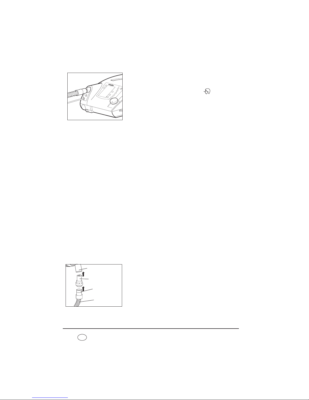
1. Connect the power cord to the power connector of
the device.
To do this, lift the cable-securing clip, plug the plug
into the power connector and flip the cable-securing
clip over the plug. Always secure the power plug with
the cable-securing clip to prevent the plug being
removed by mistake.
2. Connect the power cord to a power supply socket.
The therapy device is designed for a supply voltage of
115 V ~ and 230 V ~.
The green LED for power supply comes on and the
start screen appears in the display.
Now leave the device connected to the power supply for at least 6 hours to charge the
internal battery.
The device is now operational.
4.2 Patient/ventilator interfaces
The therapy device is intended for operation with nasal masks, oronasal masks and full-face
masks as well as with mouthpieces, endotracheal cannulas and endotracheal tubes. It is
essential to follow the instructions for use of the patient/ventilator interface in question.
4.3 Connect valve ventilation
When using valve ventilation, patient/ventilator interfaces with leakage openings may not
be used. Always use a patient valve. Inspiration and exhalation is controlled using the
patient valve.
4.3.1 Single patient circuit
The single patient circuit consists of a ventilation tube, a pressure-measurement tube, a
valve control tube and a patient valve. The patient/ventilator interface must be connected
directly to the patient valve.
Cable-securing clip
Page 40

40 Set up device
EN
Caution!
The patient valve may not be covered when the device is in operation, otherwise
the exhaled air may not be routed away, obstructing breathing.
Proceed as follows to connect the single patient circuit to the therapy device.
1. Plug the free end of the ventilation tube (2) onto the
device outlet port.
2. Now connect the blue connector stub of the pressuremeasurement tube (1) to the connection of the device
which is likewise blue and marked .
3. Connect the valve control tube (3) to the connection
of the device marked .
4. Connect the patient valve (4) to the patient/ventilator
interface, e.g. a mask.
It is essential to follow the instructions for use of the
patient/ventilator interface and of the patient circuit.
4.3.2 Double patient circuit (VENTIlogic LS only)
In addition to the ventilation tube which delivers air to the patient, the pressuremeasurement tube and the valve control tube, the double patient circuit also has an
exhalation tube which routes exhaled air back to the device and into the ambient air.
On the double patient circuit, the patient valve is located on the exhalation tube.
Proceed as follows to connect up the double patient circuit.
1. Plug the ventilation tube (1) onto the device outlet
port of the VENTIlogic LS.
2. Plug the exhalation tube (3), on the end of which is
the patient valve (4), onto the device inlet port for
exhaled air underneath the device outlet port.
3. Now connect the blue connector stub of the pressuremeasurement tube (2) to the connection of the device
which is likewise blue and marked .
1
3
2
4
P
1
3
2
4
1
2
3
4
5
P
Page 41

Set up device 41
EN
The pressure-measurement tube is the same length as
the ventilation tube and leads to the Y-connecting
piece where the ventilation tube and the exhalation
tube are brought together.
4. Connect the valve control tube (5) to the connection
of the device marked .
The valve control tube leads straight from the patient
valve to the connection on the device and is therefore
shorter than the pressure measuring tube.
5. Connect the patient/ventilator interface, e.g. a mask.
It is essential to follow the instructions for use of the
patient/ventilator interface and of the patient circuit.
4.4 Connect leakage ventilation
Connect leakage ventilation using click adapter
Proceed as follows to connect up the leakage circuit.
1. Plug the click adapter of the patient circuit onto the
ventilation outlet on the device.
2. Connect the patient/ventilator interface, e.g. a mask.
It is essential to follow the instructions for use of the
patient/ventilator interface and of the exhalation
system.
Connect leakage ventilation using standard tapered connector
For leakage operation, an adapter is available as an option to allow tubes with sleeves with
an internal diameter of Ø 22 mm and a pressure-measuring tube with an internal diameter
÷ Ø 5 mm to be used. If the device is equipped with this adapter, proceed as follows to
connect the tube:
1
2
3
5
4
Page 42
42 Set up device
EN
1. Push the ventilation tube onto the device outlet port
of the therapy device.
2. Now connect the pressure-measurement tube to the
connection on the device marked .
3. Connect the patient/ventilator interface, e.g. a mask.
4. It is essential to follow the instructions for use of the
patient/ventilator interface and of the exhalation
system.
5. Note that maximum flow rate and the accuracy of
dynamic pressure may deviate if you are not using
Weinmann tubes.
Information relating to a separate exhalation system
Caution!
Always use an exhalation system. Used air containing carbon dioxide escapes from
the patient/ventilator interface (e.g. a mask) through the exhalation system.
Without an exhalation system, the CO
2
concentration in the patient/ventilator
interface and the ventilation tube would rise to critical values and thus obstruct
breathing.
An exhalation system can either be integrated in the patient/ventilator interface, e.g. a
mask, or must be plugged in between the patient/ventilator interface and the patient
circuit in the form of an accessory.
If the patient/ventilator interface, e.g. the mask, does not have an exhalation system, a
separate exhalation system, e.g. Silentflow 2, must be used.
The exhalation system also allows a patient to breathe through his or her nose for a short
time, even if the device were to fail. In the case of full-face masks, breathing in the event
of a fault is through an emergency exhalation valve on the mask.
Connect separate exhalation system (only with leakage ventilation)
To connect a separate exhalation system, proceed as
follows.
1. Plug the exhalation system into the sleeve of the
circuit.
2. Connect the patient/ventilator interface to the
exhalation system.
P
Exhalation system
Circuit
Sleeve
Patient/ventilator
interface
Page 43

Set up device 43
EN
Follow the instructions for use for the exhalation system and for the patient/ventilator
interface.
Connect circuit for mouthpiece ventilation
Proceed as outlined below to connect the leakage circuit
for mouthpiece ventilation (WM 27651).
1. Plug the tube adapter supplied onto the ventilation
outlet on the device.
2. Plug the leakage circuit for mouthpiece ventilation
onto the tube adapter.
3. Connect the patient/ventilator interface, e.g. a
mouthpiece. It is essential to follow the instructions for
use for the patient/ventilator interface..
4.5 Connect humidifier
Note!
An optional tube adapter is available as an accessory for the use of Fisher & Paykel humidifiers. Be aware that technical data change when third-party humidifiers are used.
4.5.1 Leakage ventilation
We recommend humidifier HC 150 from Fisher & Paykel with the corresponding patient
circuit. Follow the associated instructions for use..
4.5.2 Valve ventilation
We recommend humidifiers HC 850 or HC 550 from Fisher & Paykel with the corresponding
patient circuit or humidifier PMH5000 from Wilamed.
4.6 Connect bacteria filter
Caution!
The bacteria filter represents an additional resistance in the air flow. This can cause
a change to the response characteristics of the trigger. If a bacteria filter is
connected subsequently, the doctor must therefore check the device parameters
and may need to reset them.
Tube adapter
WM 27651
Page 44

44 Set up device
EN
Note:
The bacteria filter may not be operated on the device for more than 24 hours.
Follow the instructions relating to period of use in “6. Hygiene treatment” on
page 67.
If the therapy device is intended for use by several patients (e.g. in a hospital), a bacteria
filter must be used to prevent infections.
4.6.1 Leakage ventilation
In combination with leakage ventilation, use bacteria
filter WM 24148.
If the bacteria filter is used alone, it is connected directly
to the device outlet port and the ventilation tube is
plugged onto the bacteria filter.
4.6.2 Valve ventilation
In combination with valve ventilation, use bacteria
filter WM 27591.
If the bacteria filter is used alone, it is connected directly
to the device outlet port and the ventilation tube is
plugged onto the bacteria filter.
If a humidifier and/or an oxygen sensor is to be connected as well, a different sequence
applies.
Combination with a humidifier
1. Connect the bacteria filter directly to the therapy device.
2. Connect the humidifier to the outlet of the bacteria filter.
3. Connect the patient circuit to the humidifier.
Combination with an oxygen sensor
1. Connect the oxygen sensor directly to the therapy device.
2. Connect the bacteria filter to the outlet of the oxygen sensor.
3. Connect the patient circuit to the bacteria filter.
WM 24148
WM 27591
Page 45

Set up device 45
EN
Combination with an oxygen sensor and a humidifier
1. Connect the oxygen sensor directly to the therapy device.
2. Connect the bacteria filter to the outlet of the oxygen sensor.
3. Connect the humidifier to the outlet of the bacteria filter.
4. Connect the patient circuit to the humidifier.
4.7 Therapy with oxygen supply
4.7.1 Supplying oxygen
Warning!
• If oxygen is being supplied to the respiratory flow, smoking and naked flames
are forbidden. Risk of fire. The oxygen can accumulate in clothing, bed linen
or hair. It can only be removed by thorough ventilation.
• To supply oxygen, use only the therapy device connection provided for this
purpose. Otherwise the oxygen supply cannot be stopped automatically if a
fault occurs. Never supply oxygen via masks or the T-adapter.
Note:
Supplying oxygen via a connection not intended for this purpose leads to an
erroneous volume display, as the oxygen flow cannot be included in the
measurement.
A supply rate of max. 15 l/min at < 1000 hPa pressure at the inlet for the oxygen supply is
permitted.
Use an oxygen sensor to monitor oxygen supply.
The oxygen source must have an independent flow regulation device. Ensure that you only
set the oxygen flow rate prescribed by the doctor on your oxygen supply device. It is
essential in this case to follow the safety instructions for handling oxygen as well as the
instructions for use of the oxygen device used.
Caution!
If the oxygen is humidified before being supplied, a tank with an overpressure valve
must be used, otherwise an overpressure will result in the event of faulty operation
which could lead to the humidification tank bursting or to the oxygen supply tubes
slipping off.
Page 46
46 Set up device
EN
Proceed as follows to supply oxygen:
1. Switch on the therapy device.
2. Connect the O2 coupling supplied to the connector
stub provided on the therapy device.
3. Connect the oxygen source to the O2 coupling.
4. Start the supply of oxygen. When doing so, it is
essential to follow the instructions for use of the
oxygen source in question. The device can now be
operated normally.
Proceed as follows to end supply of oxygen:
1. Shut off the oxygen supply.
2. Continue operating the device for a while without an oxygen supply to flush the
remaining oxygen out of the device. If this instruction is not followed, there is a risk of
fire in the event of a malfunction.
3. Remove the adapter for the oxygen supply from the device.
4. Switch off the device. The safety valve for the oxygen supply automatically shuts off the
oxygen supply after 1 minute.
Oxygen can be supplied via an oxygen concentrator (e.g. Weinmann Oxymat 3), via the
central gas supply system (only with corresponding pressure reducer) of a hospital, in the
form of liquid oxygen with a continuous flow or of an oxygen cylinder with a corresponding
pressure reducer.
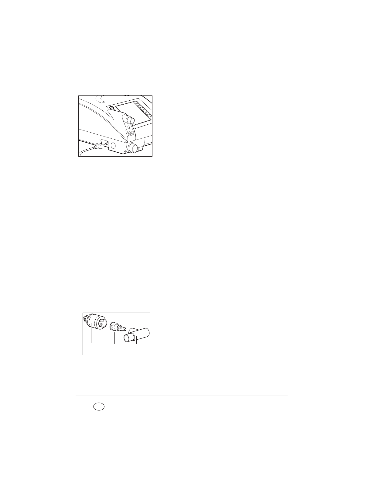
4.7.2 Measure oxygen concentration (only valve ventilation)
The oxygen sensor can only be used in conjunction with valve ventilation.
During measurement, oxygen concentration is averaged over several breaths and
displayed. Measured values depend on therapy pressure and on the temperature of
ambient and respiratory air. This is not a FiO
2
measurement, but the mean value of oxygen
concentration on inspiration.
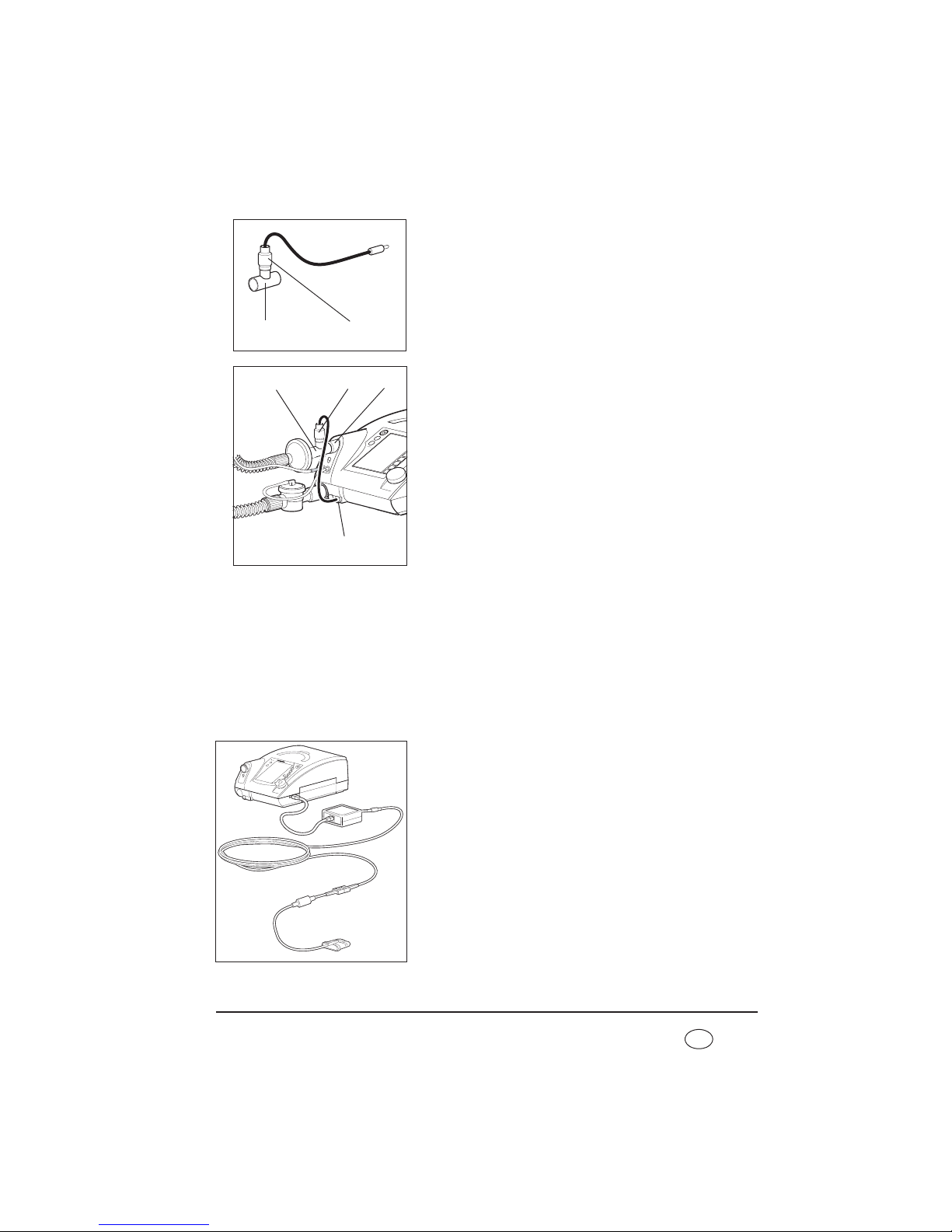
1. The adapter is delivered in three parts: the oxygen
sensor (1), the T-adapter (3) and an air management
adapter (2). Screw the air management adapter onto
the oxygen sensor.
3
2
1
Page 47
Set up device 47
EN
2. Plug the oxygen sensor (1) and air management
adapter into the T-adapter (3).
3. Plug the T-adapter (3) onto the device outlet port (5).
4. Connect the sensor (1) to the oxygen measuring jack
(4) with the aid of the cable.
5. Connect the patient circuit - with a bacteria filter if
required - as shown in the illustration.
6. Calibrate the oxygen sensor (see “7.3 Calibrate
oxygen sensor (only valve ventilation)” on page 78).
4.7.3 Measuring oxygen saturation and pulse
Using the optional, non-invasive SpO2module, oxygen saturation levels (SpO2), heart rate
and alarms can be measured, showed on the display of the device and saved to the SDcard.
The SpO
2
and heart rate parameters can each be monitored using upper and lower alarm
limits, synchronized using VENTIviews software and represented on a computer screen
with other ventilation data.
1. Connect the SpO
2
module to the serial interface on the
device. The displays and alarms for oxygen saturation
and pulse rate are activated via this.
2. Attach the SpO2 sensor onto the fingertip and wait
until the measured values are shown on the display.
3 1
3
1
5
4
Page 48

48 Set up device
EN
Note
The SpO2module supports diagnosis and patient monitoring. The SpO2module may
only be used for diagnosis in conjunction with other indications of disease and
symptoms. No clinical assessment may be made solely on the basis of SpO
2
module
results.
Note
Use only SpO2 sensors from Weinmann to measure oxygen saturation.
4.8 Operation in the event of a power failure
If the power supply should ever fail, the internal battery of the therapy device automatically
assumes supply of the device.
The message No power supply appears. The green power supply LED goes out. The
battery operating time will depend on the load and temperature range. Detailed
information on the different loads with the corresponding battery operating times are
provided in section 11. on page 108.
As soon as the power supply is restored, the device is automatically supplied from the
power supply again and the internal battery is charged. The green power supply LED comes
on and the consecutive segments in the battery symbol indicate the charging process in the
display. If you are using a replaceable battery, then in the event of a power outage, the
replaceable battery will be used first and only then the internal battery. When the batteries
are being charged, the sequence is reversed.
Note
• If the alarm Battery capacity critical appears, action is required. In this case,
only about 25 % capacity is left. This is enough for about 15 minutes. Keep an
alternative ventilation option to hand.
• If the alarm Battery capacity highly critical appears, there is less than 10 %
capacity remaining. The device will switch itself off in a few minutes. Use the
alternative ventilation option at once.
Page 49

Operation 49
EN
5. Operation
5.1 Controls
5.1.1 Function keys
The following functions can be called up directly in
ventilation mode by pressing the relevant key on the
device.
• LIAM (insufflation) (4)
• Acknowledge alarms (3)
• Select a program
(5)
• Calibrate O
2
sensor (2)
After these keys are pressed, the corresponding menu
appears in the display. You can navigate within the menu
using the dial (see “Navigating with the dial” on
page 50).
The other functions (1) can only be operated by the doctor.
Menu key
Use the menu key to switch from Monitor to Menu.
Current values during therapy are displayed in Monitor. You can make settings to the
device in Menu.
The menu key has other functions (e.g. back) depending on context. The current function
is always displayed on the left of the display next to the menu key.
Acknowledge alarm
Use the alarm acknowledgement key to acknowledge an acoustic alarm and mute it for
120 seconds.
Vt
PEEP
IPAP
F
I : E
Menu key2
3
1
5 4
Page 50

50 Operation
EN
5.1.2 Navigating with the dial
The dial (1) is the central control of the therapy device.
You can use the dial to select menu items, navigate
within the menu windows and set values for individual
menu items.
To familiarize yourself with navigation using the dial, we
recommend switching to Menu first. Press the menu key
(2) to do so. You can then try out the functions described
below.
Select menu items
• Move the dial clockwise to move the selection bar in the display downwards.
• Move the dial anticlockwise to move the selection bar in the display upwards.
• Press the dial to confirm selection of a menu item and to open the corresponding
submenu or to select a value you want to change.
Set values
• Move the dial clockwise to increase a value.
• Move the dial anticlockwise to decrease a value.
• Press the dial to save a value.
Exit menu item
Move the dial clockwise until the selection bar in the
display is on back, cancel or close depending on
context. Then press the dial. The display switches back to
the next menu up.
Alternatively, you can exit a menu item by pressing the
menu key (back, cancel or close will appear in the
display to the left of the menu key depending on
context).
1
2
Page 51

Operation 51
EN
Select night mode
If you press the dial during therapy, you will activate night mode. The display then goes
dark so that only the bar chart with the pressure display is visible. Therapy continues as normal. The display switches back on if you press the dial again or any other key. The display
switches back on automatically if an alarm situation arises.
5.2 Start up the device
5.2.1 Operating states
Three operating states are possible on the therapy device: on, off and standby.
If the device is switched on, therapy is in progress.
In standby, the blower is switched off, but the device is immediately operational with a
brief press of the On/Off key as long as the patient circuit is connected correctly. Settings
can be made on the device in standby mode.
If the device is switched off completely, the blower and the display are likewise switched
off and no settings can be made on the device.
Note
On standby, the display switches off if it is not used for 5 minutes (applies only in
patient mode).
5.2.2 Starting up
1. Connect the device to the power supply with the aid of the power cord. The standby
screen appears in the display after about 5 seconds.
2. First, perform a function check (see “7. Function check” on page 74).
3. Connect the patient circuit to the patient/ventilator
interface. It is essential to follow the relevant
instructions for use for the patient/ventilator interface,
the patient circuit and, if appropriate, the exhalation
system.
Caution!
Always use a separate exhalation system for
leakage ventilation (e.g. Silentflow leakage
ventilation), otherwise the CO2 concentration
would rise to critical values in the patient/
ventilator interface and tube and thus obstruct
the patient's breathing.
Page 52

52 Operation
EN
4. To switch on the device, press the On/Off key
briefly. The device is now in ventilation mode. The
patient menu can be accessed via the menu key.
When Auto switch-on (only with leakage ventilation) is
activated, you can also put on the patient/ventilator
interface and switch on the therapy device by taking a
breath (see “5.4 Activate/deactivate Auto switch-on
(only leakage ventilation)” on page 55). The operating
hours and the software version appear in the display for
about 3 seconds.
The device starts to pump air through the patient circuit. The display switches to the default
display.
5.2.3 Displays on screen
Ventilation parameters such as set therapy mode,
therapy pressures (CPAP pressure only in CPAP mode)
in hPa, the selected patient circuit and current
respiratory frequency in 1/min are shown in the
display.
Note: 1.01973 hPa correspond to 1 cm H
2
O.
The bar chart shows the pressure curve for inspiration
and exhalation.
The respiratory phase change display shows whether the
current respiratory phase was triggered spontaneously
by the patient (S) or by the machine (T). Depending on
respiratory phase, the display switches from left
(inspiration) to right (exhalation).
See the section entitled “ Symbols used in the display”
on page 18 for an explanation of the other symbols in
the display.
Vt
PEEP
IPAP
F
I : E
On/Off key
Bar chart
Page 53

Operation 53
EN
5.3 Handling batteries
The device is equipped with an internal battery which supplies the therapy device with
power in an emergency.
The therapy device can also be equipped with a replaceable battery available as an
accessory.
5.3.1 Charging batteries
The batteries are charged automatically as soon as the therapy device is connected to the
electricity supply. The therapy device always charges the internal battery first, followed by
the replaceable battery (if present).
Notes
• Run from the mains for at least 12 hours prior to using the battery for the first
time.
• The batteries have no memory effect. This means you can charge the batteries
even if they are not empty.
• In typical use, the batteries have a service life of at least 600 charge/discharge
cycles. The batteries must be replaced in accordance with the intervals listed in
Section 9. on page 95. If the life of the batteries is exhausted before that, the
message Service life ended. Have internal battery replaced/Have
replaceable battery replaced appears in the display.
• Note the instructions on battery care (see “9.2.1 Care of batteries” on page 96).
1. Connect device to the power supply.
The charging process starts automatically.
2. If the display is no longer flashing and/or the display is showing 100 % capacity, the
relevant battery has been charged.
If you have a replaceable battery, you can now disconnect the device from the
electricity supply for mobile use.
5.3.2 Capacity/charge status display on device
When the device is switched on, you can read off the
capacity of the battery in the default display:
Symbol Meaning
Battery display green:
battery capacity over 25 %
Battery display orange:
battery capacity below 25 %
Page 54

54 Operation
EN
5.3.3 Battery menu
This menu gives you a summary of the state of any
batteries present. In the patient menu, select the Battery
menu item using the dial:
• Internal battery: always present and supplies the device
with power in an emergency.
• Replaceable battery: available as an option and allows
mobile use of the device independent of an electricity
supply.
• The accuracy of the display depends on the load on the
device (load due to patient breathing, current
operating temperature). The display is continuously
updated.
5.3.4 Operation with replaceable battery
You can change the battery both with the device
switched off and during operation.
Note
• Only remove the replaceable battery. The
internal battery may only be replaced by the
manufacturer, Weinmann, or an authorized
specialist dealer.
• Use only genuine Weinmann replaceable
batteries.
1. Press down the latch of the replaceable battery and
keep it depressed.
2. Remove the replaceable battery.
Battery display red:
battery capacity below 10 %
Battery not ready for use:
– battery defective or
– battery too cold or
– battery too hot
Battery not present
Page 55

Operation 55
EN
3. Push the replaceable battery into the device until you
hear the latch engage.
When the device is switched on, the symbol for the
replaceable battery appears in the status line and a
beep sounds.
4. Use the status line and the Battery menu to see the
charge status of the replaceable battery.
5.4 Activate/deactivate Auto switch-on (only
leakage ventilation)
When Auto switch-on is activated, the therapy device switches on automatically as soon as
you breathe into the patient circuit. The device does not switch off again automatically
when the patient takes off the patient/ventilator interface. You can only switch off the
therapy device using the On/Off key .
Note
Auto switch-on can only be activated or deactivated in standby mode.
1. Start up the therapy device (see “5.2 Start up the device” on page 51).
2. Press the menu key to do so. The patient menu appears in the display.
3. Use the dial to select the menu item Auto switch-on
and confirm the selection by pressing the dial. Now
select on or off using the dial. Confirm the selection
by pressing the dial. The selection bar switches back to
Auto switch-on. The current setting (on/off) is now
shown again in the Auto switch-on menu line.
4. Exit the menu again by pressing the menu key, now
assigned the back function. Auto switch-on is now
activated or deactivated.
Page 56
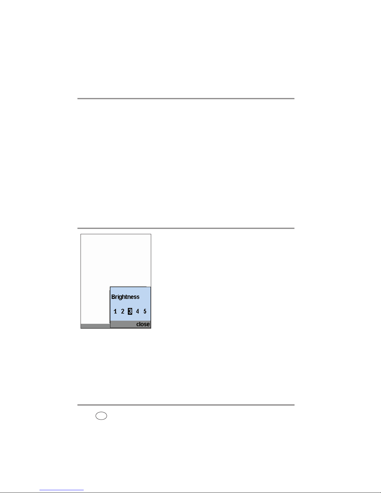
56 Operation
EN
5.5 Alarm list
5.5.1 Storage of alarms
All alarm types listed in the tables “Physiological alarms”and “Technical alarms” are
recorded in an alarm list with date, time and duration once the alarm threshold is reached.
Up to 200 alarms can be stored. After that, the oldest alarm in each case is overwritten.
To call up the alarm list, select the menu item Alarm list in the patient menu using the dial
and confirm your selection by pressing the dial.
The alarm list is retained even if the entire power supply (power supply and internal battery)
fails.
In this case, the data can be called up for up to two years. The alarm list is overwritten after
two years or when servicing is carried out.
Alarms are always retained in the event of a power failure.
5.6 Adjust brightness
You can change the brightness of the display:
1. In the patient menu, select the Brightness menu item
using the dial.
2. Select the desired brightness level using the dial.
3. Confirm your selection by pressing the dial.
Tip
To switch off the display completely during therapy (at
night for example), press the dial during therapy. Switch
the display back on by pressing the dial again.
Page 57

Operation 57
EN
5.7 LIAM info
Note
A detailed explanation of the LIAM function can be found in the section entitled
“5.10 LIAM (insufflation)” on page 58.
1. In the patient menu, use the dial to select the LIAM
info menu item.
2. Confirm your selection by pressing the dial.
You will find the following values and their residual
running times under LIAM info:
• Duration
• Interval
• Cycles
• Plateau signal (activated or deactivated)
5.7.1 Activate/deactivate plateau signal
In patient mode you can switch the plateau signal on or
off under LIAM info:
1. In the LIAM info menu, use the dial to select the
plateau signal.
2. Confirm your selection by pressing the dial.
3. Use the dial to select the status plateau signal on
or plateau signal off .
4. Confirm your selection by pressing the dial.
Page 58

58 Operation
EN
5.8 Overview
Under the menu item Displays > Summary, you can
view the current settings and alarms of the respectively
configured programs as well as the actual values.
1. In the Patient menu, use the dial to select the
Summary menu item.
2. Confirm your selection by pressing the dial.
3. Use the dial to select the desired submenu.
4. Confirm your selection by pressing the dial.
5.9 Humidifier for patient circuits with patient
valve
We recommend humidifiers HC 850 or HC 550 from Fisher & Paykel with the corresponding
patient circuit or humidifier PMH5000 from Wilamed. Follow the associated instructions for
use.
5.10 LIAM (insufflation)
5.10.1 Information about the function
LIAM stands for Lung Insufflation Assist Maneuver. LIAM is a pressure-controlled
hyperinsufflation maneuver with the aim of administering an increased tidal volume which
can be used in all ventilation modes except CPAP and SIMV. LIAM can be used to support
coughing or for alveolar recruitment (similar to ventilation on sighing). In the case of
neuromuscular diseases, in particular, LIAM can be useful in expanding both thorax and
lung. With regular use, there can accordingly be a positive impact on the course of vital
capacity.
Page 59
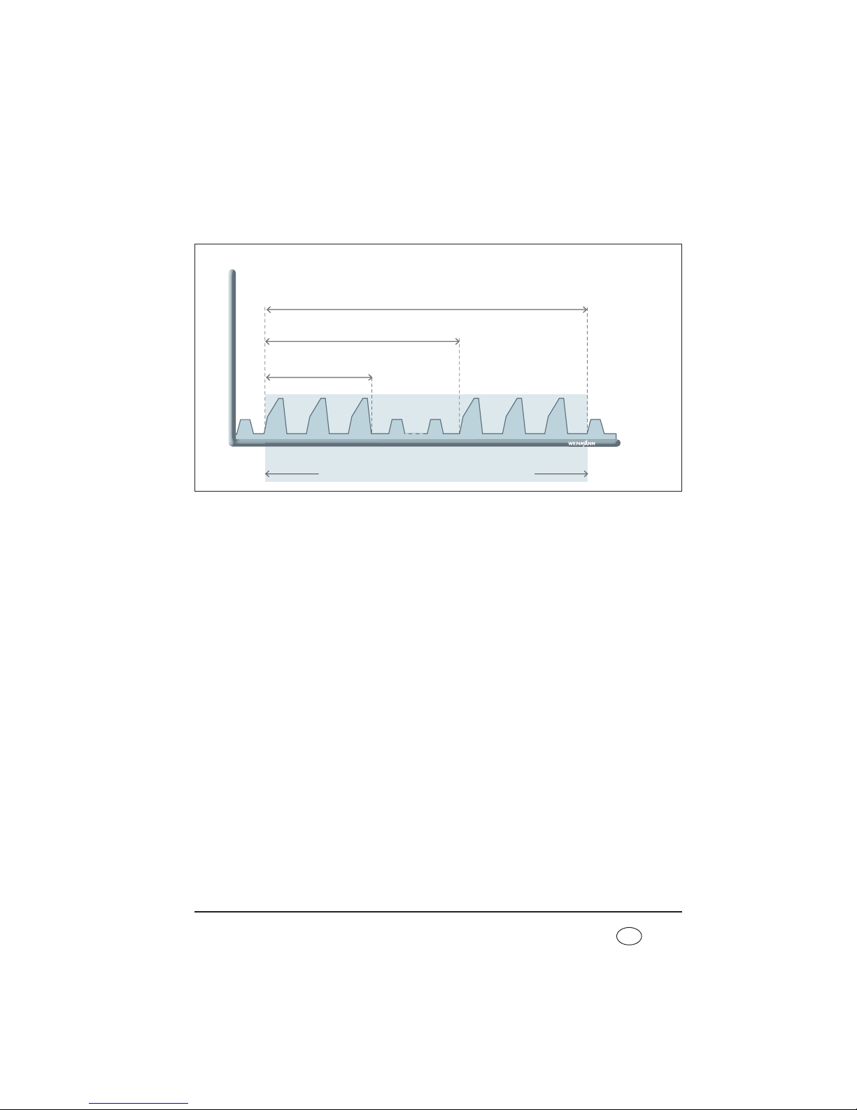
Operation 59
EN
LIAM can only be enabled by the doctor and only triggered during ventilation. The
maneuver includes at least one LIAM stroke consisting of insufflation and subsequent
exhalation.
Your doctor uses the Duration parameter to specify the period for which LIAM is applied.
The Interval parameter states at what intervals LIAM will be repeated. Within one interval,
either one LIAM stroke (Cycles = 1) or up to 10 consecutive LIAM strokes are executed.
LIAM to support a coughing maneuver
LIAM can be used to support a coughing maneuver by initially expanding lung and thorax
adequately during hyperinsufflation. This makes more air available for the subsequent
cough. At the same time, optimized initial tensioning of the lung and thorax increases the
effectiveness of the cough on exhalation.
Duration in min/h
(e.g. 20 min)
Pressure
Time
Interval in sec/min/h
(e.g. every 5 min)
Cycles
(e.g. 3 x consecutively)
Ventilation alternating with LIAM
Page 60
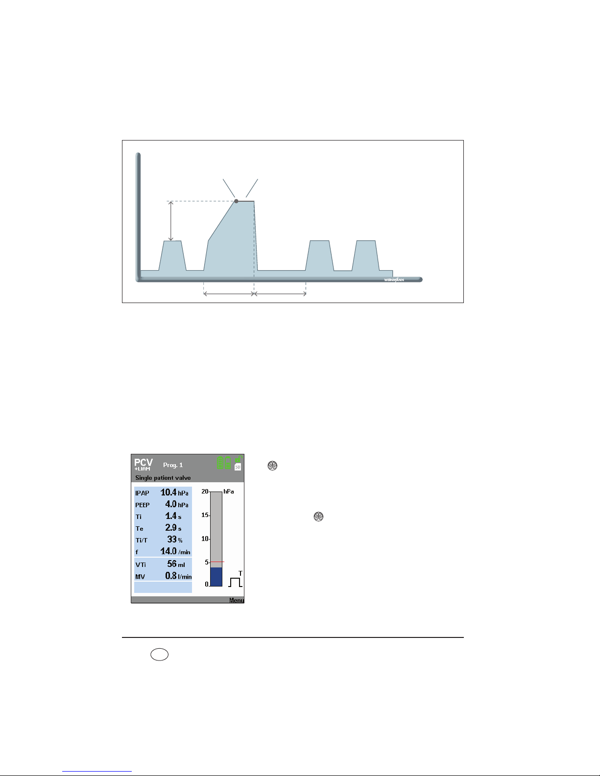
60 Operation
EN
Initially, the pressure curve within the individual LIAM stroke is comparable with a normal
ventilation stroke. When the IPAP pressure level is reached, however, pressure continues to
rise in linear form to maximum pressure IPAP
max
(IPAP + ŋP
LIAM
) and is maintained for
one second (plateau phase). The plateau phase at the end of insufflation is to facilitate
the coordination (closure of the glottis) of a coughing maneuver. The start of the plateau
phase is audibly emphasized by an optional plateau signal. This plateau signal can be
switched on and off in the menu under LIAM info (see “5.7.1 Activate/deactivate plateau
signal” on page 57). You can also have the following values displayed under LIAM info:
Duration, Interval and Cycles. LIAM ends automatically once the set duration has
elapsed or can be cancelled manually (see “5.10.3 Canceling LIAM” on page 61).
5.10.2 Method
You can trigger LIAM manually during ventilation. Press
the key to do so. The device switches to LIAM mode
and insufflation is started to synchronize with the next
inspiration.
You can perform the whole process yourself several
times. Press the key again to do so.
Pressure
Time
Ti
LIAM
Te
LIAM
IPAP
max
ŋP
LIAM
Signal which can be
switched off
1 sec. plateau phase
Page 61
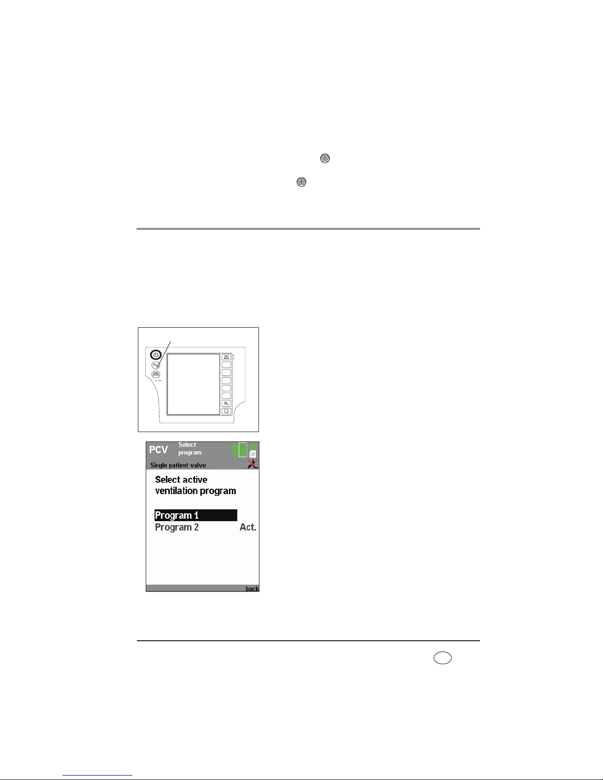
Operation 61
EN
5.10.3 Canceling LIAM
LIAM can be interrupted at any time. Press the key to do this. Then LIAM is canceled
and the device reverts to the preset ventilation mode. If LIAM is then to be carried out
again, begin the process by pressing the key again.
5.11 Select a program
Caution!
Ensure that only those ventilation programs which should be accessible for the
respective patient are enabled.
If a variety of settings are intended for one patient (mode, parameters, alarms), i.e.
ventilated with settings during the day which are different to those during the night, you
can select one of the programs configured for the patient in each case.
1. Press the program button.
2. Select the desired program and confirm your selection.
Under the menu item Displays > Summary, you can
view the current settings and alarms of the
respectively configured programs as well as the actual
values.
1 2 3
Vt
PEEP
IPAP
F
I : E
Program button
Page 62

62 Operation
EN
5.12 After use
1. Switch the device to standby by keeping the On/Off
key depressed for approx. 2 seconds until the blower
switches off. The duration of the previous therapy
appears in the display. The device then switches to
standby.
2. Disconnect the patient/ventilator interface from the
patient circuit and the patient circuit from the device.
3. Clean the patient/ventilator interface, patient circuit
and device in accordance with the instructions for use.
For information on this, see the section entitled
“Hygiene treatment” on page 67.
5.12.1 Switch device off completely
If the device is connected to a power supply, do not let it be turned off completely. To
completely disconnect the device from the power supply, turn the device to standby mode
and disconnect the device from the power supply. For optimal battery charging, however,
we recommend not to disconnect the device from the power supply.
To switch off the device completely in battery-operated mode, first switch to standby by
pressing the On/Off key for about 2 seconds until the blower switches off. Then press the
On/Off key again for at least 2 seconds until the device switches off completely and the
display goes out.
5.12.2 Mobile therapy data check
The therapy device has a memory card reader for SD cards which can be used to save
therapy data on a memory card. In discussion with the doctor supervising treatment, this
allows the patient's therapy data to be read out independently of the location of the
device, as the data can be transported on the memory card.
The following data are stored on the memory card:
– therapy pressure in hPa
– respiratory flow in l/min
– volume, leakage corrected, in ml
– current respiratory phase
– mean leakage flow in l/min
– current ratio Ti/T in %
– current respiratory frequency in 1/min
Page 63

Operation 63
EN
– ratio of spontaneous inspiration to total number of inspirations in %
– ratio of spontaneous exhalation to total number of exhalations in %
– tidal volume of last inspiration in ml
– mean respiratory minute volume in ml/min
– current physiological alarms
– current technical alarms
– current warnings
This data can be read out from the memory card and displayed with the aid of the
VENTIviews software.
If a card is in the device and therapy data is being recorded, a symbol appears in the
status line. If the symbol does not appear, the memory card is defective, absent or not yet
recognized by the device.
Caution!
Only remove the memory card when data is not being copied onto the card,
otherwise therapy data may be lost. End the therapy before removing the memory
card. Check whether the symbol is displayed in the status line. When the
symbol no longer appears in the status line, you can remove the memory card
safely.
Note
The SD card can only be detected by the device when ventilation mode is running.
After inserting the memory card, run the device briefly until the SD card is detected
and the symbol is displayed in the status line.
Proceed as follows to remove the memory card.
1. The slot for the memory card is located on the side of
the device under a rubber cover. Pull on the rubber
cover to get at the memory card.
2. To remove the memory card, press briefly on the
memory card in the device. A spring mechanism now
pushes the memory card out a little way.
3. Remove the memory card.
4. Cover the slot for the memory card again using the
rubber cover.
Page 64

64 Operation
EN
Proceed as follows to put the memory card back in.
1. Pull on the rubber cover to get at the slot for the memory card.
2. Push the memory card into the slot with the cut-off corner pointing upwards.
3. Briefly press on the card so that the card can engage in the device with the aid of the
spring mechanism.
4. Cover the slot for the memory card again using the rubber cover.
Caution!
When covering the memory card with the rubber cover, take care not to push in
the card accidentally, as doing so will eject it from the device. Ejecting the card may
cause loss of therapy data.
5.13 Travel with the therapy device
Traveling by air with the VENTIlogic LS/plus:
The terms of commercial transport do not currently apply to individuals who would like to
travel with the therapy device (see “3.1.5 Transport/accessories/spare parts/maintenance”
on page 34). The therapy device is currently permitted as checked baggage or hand
baggage for travel by plane under the applicable provisions for the carriage of dangerous
goods . You may take two spare batteries in hand baggage with the prior consent of the
airline company. As these regulations vary depending on the country, method of transport
or by changes in regulations, inquire with the airline company before every journey as to
which requirements are in place and which measures you must take.
You can obtain a certificate for in flight use and transportation which confirms the
electromagnetic compatibility (EMC) from the manufacturer Weinmann.
Page 65

Operation 65
EN
5.13.1 Bags for the therapy device
The therapy device has two bags, a protective bag (WM 27106) and a carrying bag for
mobile use (WM 27976).
The protective bag WM 27106 is supplied and is for
protecting the device but not for mobile operation.
The carrying bag WM 27976 is available as an accessory
and allows the device to be operated on a mobile basis.
5.13.2 Before starting mobile operation
You should only transport the therapy device any distance in the protective bag WM 27106
intended for it. If you want to use the therapy device on a mobile basis, you must use it in
carrying bag WM 27706.
Proceed as follows to operate the device on a mobile
basis.
1. Fit the patient circuit and the patient/ventilator
interface.
2. Now put the therapy device in the bag. The ventilation
tubes must be fed through the tube of fabric in the
process.
3. Switch on the therapy device.
4. Secure the therapy device with the hook-and-loop
closure in the bag.
5. Close the bag and check that the therapy device is
firmly secured in the bag and cannot wobble or fall
out.
Page 66

66 Operation
EN
6. Attach the tube of fabric and the ventilation tubes to
the side of the therapy device using the hook-andloop attachment provided.
Tips for use with a replaceable battery
• If you are using a replaceable battery, you can change
it without having to remove the therapy device from
the bag. Simply open the hook-and-loop closure on
the side of the bag.
The small accessories bag is provided for a second
replaceable battery. You can attach the accessories bag
to the front of the carrying bag or to the shoulder strap.
If you charge the batteries in the bag, the device may
become so hot under high load that the charging process
for the batteries is interrupted.
Only charge the battery outside the bag.
Page 67

Hygiene treatment 67
EN
6. Hygiene treatment
This product may contain disposable items. Disposable items are intended to be used
only once. So use these items only once and do not reprocess them. Reprocessing
disposable items may impair the functionality and safety of the product and lead to
unforeseeable reactions as a result of ageing, embrittlement, wear, thermal load, the
effects of chemical processes, etc.
6.1 Intervals
You should check the filters at regular intervals and wipe down the housing and the filter
compartment lid with a damp cloth. You should also observe the following intervals:
6.1.1 Leakage ventilation
Follow the relevant instructions for use on the hygiene treatment for the patient/ventilator
interface.
Interval Activity
Daily
– Clean the patient/ventilator interface in accordance with the relevant
instructions for use.
– Clean the patient circuit.
– Clean bacteria filter WM 24148 in accordance with the instructions for
use.
– Clean the exhalation system in accordance with the instructions for use
every time it is used.
Every 24 operating
hours
– Change the particulate filter in bacteria filter WM 24148.
Weekly
– Clean coarse dust filter.
– Clean fan filter.
Every 1000 operating
hours
– Change fine filter (filter change indicator ), earlier if dirty.
Every 6 months
– Change coarse dust filter, earlier if dirty or worn.
– Change pressure measuring tube (see “9.4 Change pressure-
measurement tube (only leakage ventilation)” on page 100), earlier if
dirty.
– Change fan filter.
Annually
– Change patient circuit.
Page 68

68 Hygiene treatment
EN
6.1.2 Valve ventilation
The patient circuits for single and double patient circuits with patient valve (double patient
circuit only on VENTIlogic LS) are disposables and cannot be subjected to a hygiene
treatment. Follow the instructions for use for the patient circuit in question.
Follow the relevant instructions for use for the hygiene treatment of the patient/ventilator
interface.
6.2 Clean leakage ventilation
6.2.1 Clean patient circuit
1. Pull the patient circuit off the device and the exhalation system.
2. Pull out the one end of the pressure measuring tube
(shake a little if necessary) and seal it with the sealing
plug supplied. At the other end, seal the small opening
of the adapter using the second sealing plug so that
no water can penetrate.
3. Clean the creased tube with a little detergent in hot
water and make sure no residues are left behind. Flush
the inside of the tube through thoroughly in the
process.
4. Rinse the creased tube thoroughly inside and out using clean hot water.
5. Thoroughly shake out the patient circuit.
6. Hang up the patient circuit and leave to drip-dry well to stop moisture getting into the
therapy device.
7. Remove the plugs from the pressure-measurement tube.
Interval Activity
Daily
– Clean the humidifier in accordance with the relevant instructions for
use.
– Change bacteria filter WM
27591.
Weekly
– Clean coarse dust filter.
– Clean fan filter.
Every 1000 operating
hours
– Change fine filter (filter change indicator ), earlier if dirty.
Every 6 months
– Change coarse dust filter, earlier if dirty or worn.
– Change fan filter.
Page 69
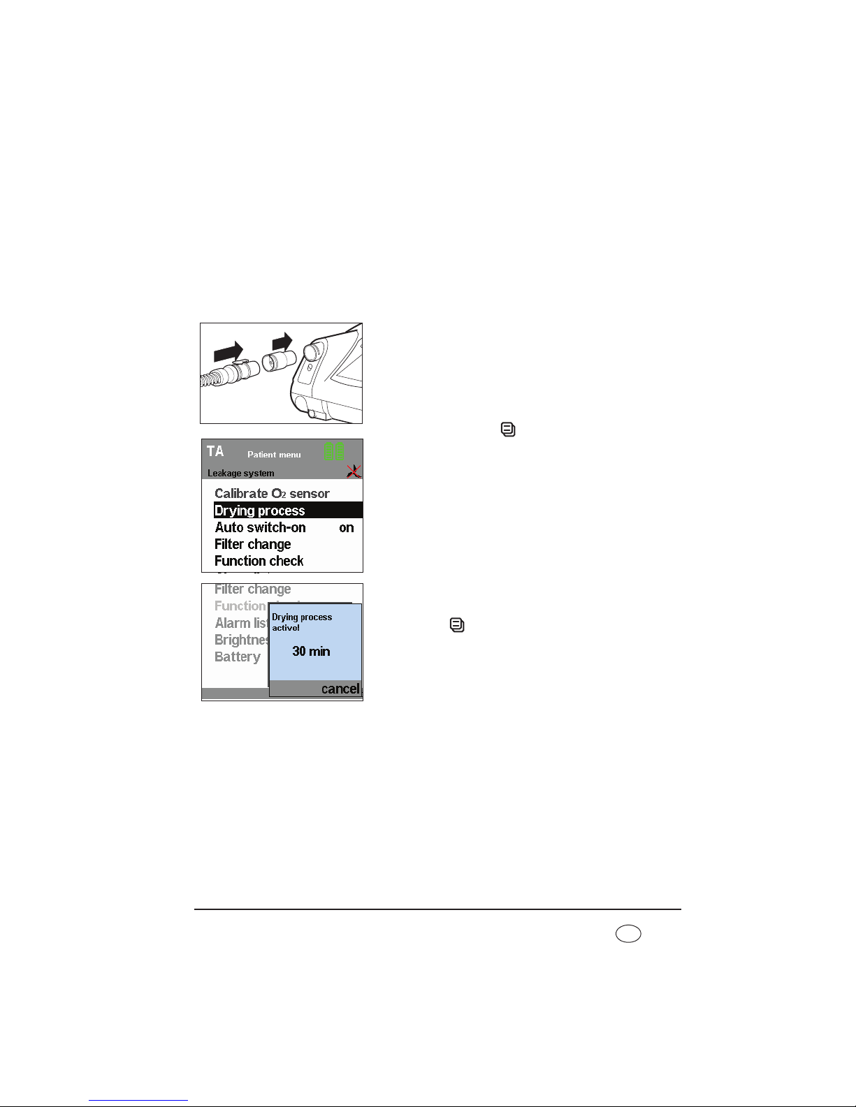
Hygiene treatment 69
EN
6.2.2 Dry the patient circuit using the therapy device
If water ever gets into the pressure measuring tube by accident, the
leakage circuit must be dried with the aid of the therapy device.
This function can only be activated in standby mode. Likewise press the
On/Off key to switch the device to standby.
To start the drying process, proceed as follows.
1. Plug the red drying adapter supplied into the device
outlet port.
2. Plug the adapter for the patient circuit onto the red
drying adapter.
3. Press the menu key to do so. The patient menu
appears in the display.
4. Use the dial to select the menu item Drying process
and confirm this selection by pressing the dial.
The message Drying process active! 30 min appears.
This display remains active throughout the entire
drying process and indicates remaining drying time.
After the drying process is complete, the device
switches off.
5. If you want to interrupt the drying process, press the
menu key (cancel). The display switches back to
the default display, the device switches back to
standby.
If the patient circuit still has damp places after drying,
start the drying process again.
6. Remove the drying adapter from the device outlet port.
Page 70

70 Hygiene treatment
EN
6.3 Clean the housing
Warning!
• Risk of electric shock. Switch the device off completely before cleaning (see
“Switch device off completely” on page 62).
• Ensure that no liquids get into the device. Never immerse the device in
disinfectants or other liquids, otherwise damage to the device and thus a hazard
to users and patients may result.
Proceed as follows to clean the housing.
1. Wipe down the device and the power cord with a soft damp cloth. The therapy device
must be completely dry before the device is started up.
2. Take off the filter compartment lid.
3. Remove the coarse dust filter as described in
“9.3 Change filter”.
4. Clean the filter compartment lid under running water
until there are no residues. Then dry it carefully.
5. Insert the coarse dust filter and the filter compartment
lid as described in “9.3 Change filter” on page 97.
6. Remove the fan filter on the front of the device and clean it as described in
“9.3 Change filter”.
7. Put the fan filter back in.
6.4 Clean coarse dust filter/change fine filter
1. Take off the filter compartment lid as described in “9.3 Change filter”.
2. Remove the coarse dust filter from out of the filter compartment lid and clean it with
clean running water until there are no residues.
3. Change the fine filter if required.
4. Allow the coarse dust filter to dry. The coarse dust filter must be completely dry before
the device is started up.
5. Put the coarse dust filter back in and close the filter compartment lid.
Note:
The fine filter cannot be cleaned. It is changed every 1000 operating hours.
Page 71

Hygiene treatment 71
EN
6.5 Clean the fan filter
The fan filter protects the housing fan from dirt.
To clean the fan filter, proceed as follows:
1. Remove the fan filter according to the instructions in section “Change fan filter” on
page 99.
2. Clean the fan filter with fresh running water until it is free of residue.
3. Let the fan filter dry. The fan filter must be completely dry before starting the device.
4. Insert the fan filter again according to the instructions in section “Change fan filter”
on page 99.
6.6 Clean the accessories
To clean the accessories, see the section entitled "Hygiene treatment" in the
corresponding instructions for use.
6.7 Clean the SpO2module
The housing of the SpO2module should be cleaned at regular intervals depending on
contamination.
Wipe the SpO
2
module and the connecting cable with a soft damp cloth.
6.8 Disinfect, sterilize
If required, e.g. following infectious diseases or unusual contamination, you can also
disinfect the housing, the power cord, the patient circuit (leakage ventilation only) and the
bacteria filter housing (leakage ventilation only). See the instructions for use for the
disinfectant used. We recommend wearing suitable gloves (e.g. household or disposable
gloves) for disinfecting.
6.8.1 Device
The housing and the power cord of the therapy device are cleaned simply by wiping with
disinfectant. We recommend terralin
®
protect for this purpose.
Page 72

72 Hygiene treatment
EN
6.8.2 Patient circuit (leakage ventilation)
We recommend GIGASEPT FF as disinfectant. When using GIGASEPT FF, take the same
steps as described under “6.2 Clean leakage ventilation”.
Rinse all parts thoroughly in distilled water following disinfecting. Allow the parts to dry
completely.
Allow the patient circuit to drip dry. Dry the patient circuit with the therapy device as
described in section 6.2 on page 68.
• Creased hose WM 24130 (transparent) can be washed in water at temperatures
of up to 70 °C. It may not be sterilized.
• Creased tube WM 24120 (gray) can be steam-sterilized with devices to EN 285.
Temperature: 134 °C, minimum retention time 3 minutes. Follow EN 554/
ISO 11134 with regard to validation and monitoring.
6.8.3 Patient circuit (valve ventilation)
Patient circuits with patient valve are not suitable for reuse.
Follow the enclosed instructions for use in this regard.
6.8.4 Oxygen sensor
The housing of the oxygen sensor is cleaned by wiping with disinfectant. No further
cleaning or hygiene treatment is possible. If the oxygen sensor has been used without a
bacteria filter before a change of patient, it must be replaced.
6.8.5 Accessories
To disinfect/sterilize the accessories, see the section entitled “Hygiene treatment” in the
corresponding instructions for use.
6.8.6 SpO2module
Sterilization of the SpO2module is not permitted.
If required, e.g. following infectious diseases or unusual contamination, you can also disinfect
the housing of the SpO
2
module and the connecting cable. We recommend terralin® protect
for this purpose. See also the instructions for use for the disinfectant used. We recommend
using suitable gloves (e.g. household or disposable gloves) when disinfecting.
Page 73

Hygiene treatment 73
EN
6.9 Change in patients
If the device is operated with a bacteria filter, observe the following.
• Change bacteria filter WM 27591
or:
• sterilize bacteria filter WM 24148 and change the particulate filter inside it.
If the device is to be used for another patient without a bacteria filter being used, it must
be subjected to a hygiene treatment beforehand. This must be performed by the
manufacturer, Weinmann, or by an authorized specialist dealer.
The procedure for hygiene treatment is described in the service sheet and in the servicing
and repair instructions for the therapy devices.
Page 74

74 Function check
EN
7. Function check
7.1 Intervals
Perform a function check of the device monthly. One exception to this is the oxygen sensor.
The oxygen sensor needs calibrating daily.
We recommend checking the battery capacity before each use.
If you discover faults during the function check, you may not use the therapy device again
until the faults have been rectified.
7.2 Method
1. Assemble the therapy device so that it is ready to function.
2. Seal the opening of the patient circuit, e.g. with a sealing plug. For hygiene reasons,
suitable disposable gloves should be worn if you seal the opening of the patient circuit
with your thumb or hand.
3. Switch on the device by pressing the On/Off key . If the device works perfectly, two
different acoustic signals should sound after switching on and both LEDs next to the
alarm acknowledgement key should come on.
Depending on the operating mode set, now test the following functions:
If the values/functions quoted below are not met, send the device to your specialist dealer or
to the manufacturer, Weinmann, for repair.
* These modes are only available with VENTIlogic LS.
Mode
Function
S T ST CPAP PCV aPCV PSV VCV* aVCV* SIMV MPVv MPVp
Triggering
•
-
•
- -
• •
-
• • • •
Flow sensor/
pressure
sensor
• • • • • • • • • • • •
Alarms
• • • • • • • • • • • •
Oxygen
supply
• • • • • • • • • •
- -
Page 75

Function check 75
EN
7.2.1 Check flow measurement and flow sensors/pressure sensors
(leakage ventilation)
Note:
A function check of the flow sensors/pressure sensors can only be carried out in
standby mode.
1. Plug the red drying adapter supplied into the device outlet port.
2. For hospital staff only: Ensure that the patient circuit set on the device is the same as
the patient circuit actually in use.
3. Press the menu key to access patient mode.
4. Use the dial to move the black selection bar to
Function check and press ENTER.
5. Confirm the function check in the following window.
The message window Function check running!
opens. The remaining duration of the function check
is displayed.
6. If the function check is completed successfully, the
message Function check ok! appears.
If the function check is not successful, the message
Device system implausible appears. In this case
refer to section “8.1 Faults” on page 81.
7. Press the menu key to return to the standard display.
Page 76
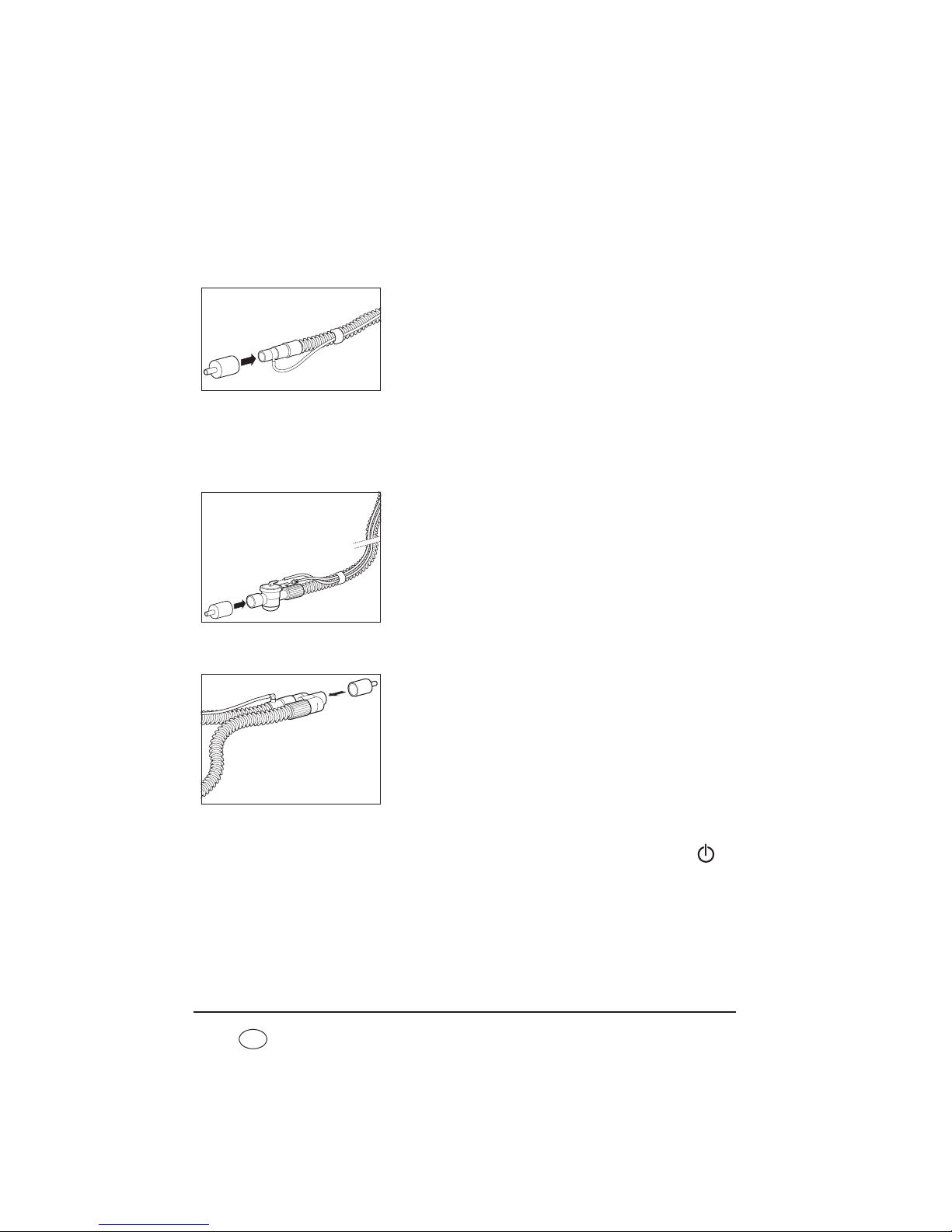
76 Function check
EN
7.2.2 Check flow measurement and flow sensors/pressure sensors
(leakage ventilation with leakage adapter for standard
tapered connector)
1. Connect the patient circuit to the device.
2. Plug the test adapter supplied onto the patient
connection.
3. Perform the subsequent steps as descibed in “7.2.1
Check flow measurement and flow sensors/pressure
sensors (leakage ventilation)” from step 2.
7.2.3 Check flow measurement and flow sensors/pressure sensors
(valve ventilation)
Function check using a single patient circuit with patient valve
1. Connect the patient circuit to the device.
2. Plug the test adapter supplied onto the patient
connection.
3. The subsequent steps are described in “7.2.1 Check
flow measurement and flow sensors/pressure sensors
(leakage ventilation)” starting from step 2.
Function check using a double patient circuit with patient valve (VENTIlogic LS
only)
1. Connect the patient circuit to the device.
2. Plug the test adapter supplied onto the patient
connection.
3. The subsequent steps are described in “7.2.1 Check
flow measurement and flow sensors/pressure sensors
(leakage ventilation)” starting from step 2.
7.2.4 Alarms
The therapy device performs a self-test on the sensor system when the On/Off key is
pressed which also checks that the alarm system is working. If a fault occurs during the selftest, an error message appears in the main screen (see also “8. Troubleshooting” on
page 81).
1. Check buzzer and LEDs:
Page 77

Function check 77
EN
Ensure each time you switch on that two different acoustic signals sound one after the
other and that the yellow and red LEDs come on at the same time.
2. Check the No power supply alarm (power supply failure alarm):
Start up the therapy device. Now take the power cord out of the socket. The internal
battery assumes power supply, the two buzzers sound and the yellow LED comes on.
The low-priority alarm window No power supply appears. Plug the power cord into
the power socket again. The alarm should no longer be displayed.
7.2.5 Oxygen supply
Caution!
If a compressed gas system is used instead of an oxygen concentrator, an
overpressure valve must be fitted.
Note:
A function check can only be performed on the oxygen supply if the oxygen supply
has been activated by the doctor beforehand (flow meter or oxygen concentrator).
In order to carry out a function check on the oxygen supply, proceed as follows:
1. Start up the therapy device.
2. Connect the oxygen source to the therapy device and start it up.
3. At the oxygen source, set the oxygen flow to the value prescribed by the doctor.
4. Select one of the following procedures depending on whether or not you are using an
oxygen sensor.
With an oxygen sensor
Ensure that the oxygen sensor is connected correctly and has been calibrated beforehand.
The oxygen supply is functioning properly if an oxygen concentration of > 21 % is
shown on the display and the oxygen flow rate prescribed can be set on the oxygen
source.
Without oxygen sensor
The oxygen supply is functioning properly if the oxygen flow rate prescribed can be set
on the oxygen source.
Page 78

78 Function check
EN
7.3 Calibrate oxygen sensor
(only valve ventilation)
7.3.1 General
If oxygen is supplied during therapy, oxygen concentration is measured at the device outlet
port so as to ensure that the patient is always adequately supplied with oxygen.
To ensure the accuracy of the measurement, calibration should be performed daily.
Calibration is necessary in the case of
– unsettled weather (air pressure, temperature) or
– changes in therapy pressure.
Always perform calibration with the device warmed up (approx. 20 minutes after switching on).
Perform calibration of the oxygen sensor once a day to avoid the weather affecting
measuring results. The device will issue the relevant message each day to remind you to
perform calibration. This message also appears if:
– the device has previously been disconnected from the power supply
– 24 hours have passed since the last calibration
– the oxygen sensor has been disconnected electrically from the device and then
reconnected.
Note
The sensor is calibrated at a proportion of 21 % oxygen (ambient air). Turn off the
oxygen supply on the oxygen source (flow meter or oxygen concentrator) for this.
7.3.2 Precautions
Take the following precautions when calibrating.
1. Shut off the oxygen source.
2. Operate the device for approx. two minutes without an oxygen supply to flush out the
remaining oxygen in the device.
Page 79
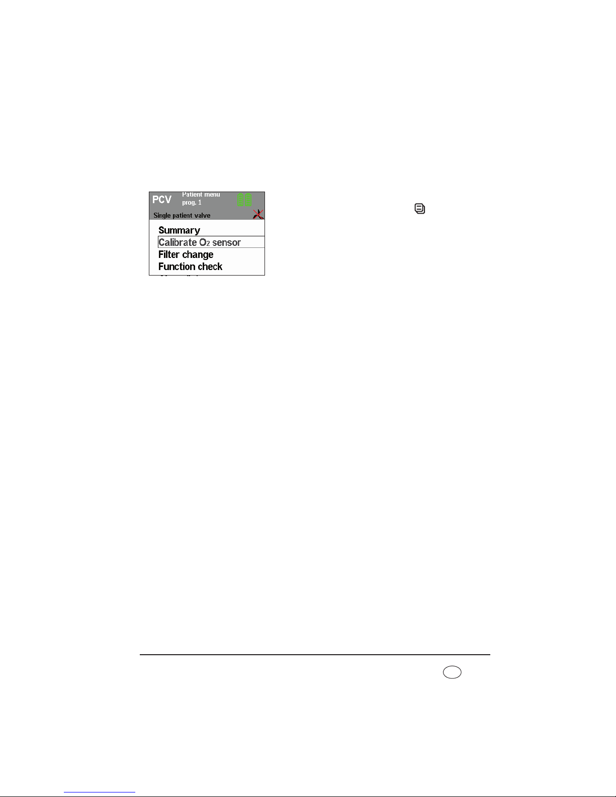
Function check 79
EN
7.3.3 Perform calibration
Proceed as follows for calibration.
1. Ensure that the oxygen sensor is connected.
2. Operate the device.
3. Press the O2 key or the menu key . The selection
bar is on Calibrate O2 sensor.
4. Confirm your selection by pressing the dial.
Remaining calibration time is displayed.
The device then automatically switches back to the
patient menu.
5. Check the display: the oxygen sensor is working
perfectly if mean oxygen concentration is 21 %.
7.3.4 Shelf life of the oxygen sensor
The shelf life of the oxygen sensor depends on the concentration of the oxygen supplied, on
ambient temperature, on duration of use and on the device settings. Under normal conditions
(ambient temperature 21 °C, 40 % oxygen concentration) the sensor lasts 6 months.
Note:
The sensor becomes exhausted even if it is not connected.
7.3.5 Change oxygen sensor
Once the oxygen sensor is exhausted, remove it from the device. Connect a new oxygen
sensor as described in “Measure oxygen concentration (only valve ventilation)” on
page 46.
Note:
Depending on storage time and temperature, the sensor requires a little time for
measured values to stabilize. As a result, after unpacking from the original
packaging and connecting the sensor, you should wait about 30 minutes before
calibrating the new sensor.
Page 80

80 Function check
EN
7.4 Energy supply
7.4.1 Power supply
Connect the device to the power supply.
The power supply is working perfectly if the green power supply LED comes on
permanently and the standby screen appears in the display.
7.4.2 Internal battery and energy failure alarm
1. If present: remove the replaceable battery (see “5.5 Alarm list” on page 56).
2. For the procedure for the function check of the power supply failure alarm, see the
chapter entitled “Alarms” on page 76.
If supply is not assumed by the battery without interruption, either this or the therapy
device is defective. In this case have the device including its internal battery checked by
an authorized specialist dealer or by Weinmann.
3. Check battery capacity (shown in the status line of the display).
If fewer than three segments are displayed in the battery symbol, the battery is not fully
charged. In this case, charge the battery by connecting the device to the power supply.
7.4.3 Replaceable battery (if present)
1. Push the replaceable battery into the device until you hear the latch engage.
The symbol for the replaceable battery appears on the right next to the internal battery
in the status line and a beep sounds.
2. Check battery capacity (shown in the status line of the display):
If fewer than three segments are displayed in the battery symbol, the battery is not fully
charged. In this case, charge the battery by connecting the device to the electricity
supply.
Replaceable batteries which have been stored for over a month must be charged up
before they are used to guarantee an accurate display.
Page 81

Troubleshooting 81
EN
8. Troubleshooting
8.1 Faults
Caution!
If faults occur which cannot be eliminated at once, contact the manufacturer,
Weinmann, or your specialist dealer immediately to have the device repaired. Do
not continue operating the device in order to prevent even greater damage.
Fault/fault message Cause of fault Remedy
Device cannot be
switched on by taking a
breath
Auto switch-on not
activated
Activate Auto switch-on (only leakage
ventilation) (5.4, Page 55)
Valve ventilation
connected
Filter change
Filter dirty
Press alarm acknowledgement key,
clean/change filter as soon as possible (6.4,
Page 70)
Filter change indicator
appears
Clean/change filter as soon as possible (6.4,
Page 70)
Battery discharged
Internal battery of device
exhausted
Press alarm acknowledgement key, have battery
replaced by a specialist dealer so that course of
therapy is recorded correctly
Clock not set Internal clock not set
Press alarm acknowledgement key, have clock
set by a specialist dealer so that course of
therapy is recorded correctly
Arrange maintenance
Maintenance interval
expired
The device needs to be checked or serviced by
Weinmann or a specialist dealer as soon as
possible
Service indicator
appears
Page 82

82 Troubleshooting
EN
Calibrate O2 sensor
Initial contact with
oxygen sensor
Perform calibration of oxygen sensor
Oxygen supply has not
been turned off
Last calibration
performed over 24
hours ago
Device was switched off
completely beforehand
Blower failure
Blower no longer
working
Have device repaired
Internal batt. not
charging due to
overtemperature
Battery too hot
Protect device from direct sunlight, do not
operate near a radiator
Internal batt. not
charging due to
overtemperature
Battery too cold
Ensure that the device is operated within the
permitted temperature range
Replaceable battery not
detected
Battery defective Have device repaired
Non-approved battery in
use
Use genuine Weinmann battery
Using the WM 27998
battery with a firmware
version < 2.9.0
Update the firmware to version 2.9.0 or above
Replaceable battery is
hard to push in or jams
Particles of dust in guide
rails
Clean guide rails on replaceable battery and
lower part of housing
Service life ended.
Have replaceable battery
replaced.
The replaceable battery
has reached the end of
its service life.
Replace the replaceable battery.
Service life ended.
Have internal battery
replaced.
The internal battery has
reached the end of its
service life.
Replace the internal battery.
Device cannot be
switched on (battery
operation)
Transport securing
device for battery is
active.
The battery fitted is deactivated for transport
purposes. Before using for the first time, connect
the power supply and charge battery.
SpO
2
measurement
disconnection
SpO
2
sensor has slipped
out of place or come
loose from the fingertip
Attach the SpO
2
sensor to the fingertip properly
Fault/fault message Cause of fault Remedy
Page 83

Troubleshooting 83
EN
8.2 Alarms
A distinction is made between two kinds of alarm.
• Physiological alarms are those alarms which affect the patient's ventilation
directly.
• Technical alarms are those alarms which affect the configuration of the device.
The alarms are classified into three priorities:
• low-priority alarms, indicated by the symbol in the alarm window, a
continuously illuminated yellow LED and an acoustic alarm issued (buzzer)
• medium-priority alarms, indicated by the symbol in the alarm window,
a flashing yellow LED and an acoustic alarm issued (buzzer)
• high-priority alarms, indicated by the symbol in the alarm window,
a flashing red LED and an acoustic alarm issued (buzzer)
8.2.1 Deactivate alarms
The doctor supervising treatment can decide which physiological alarms to activate or
deactivate. If the symbol appears in the status line, all the physiological alarms have
been deactivated by the supervising doctor (see “Physiological alarms” on page 84).
8.2.2 Acknowledging alarms
If a fault triggers an alarm (in this case: disconnection
alarm), you can have the acoustic alarm paused for about
120 seconds by pressing the alarm acknowledgement
key .
SpO2 signal weak
Nail varnish, dirty fingers
Check SpO2 sensor and fingertip and clean if
need be
Patient shock Check patient condition
Fault/fault message Cause of fault Remedy
Page 84

84 Troubleshooting
EN
The default display appears again after the acoustic
alarm has been acknowledged. The fault which has not
yet been rectified continues to be displayed in the status
line and the alarm LED flashes (or stays on) until the fault
is rectified.
If the fault is not rectified within 120 seconds of the
acknowledgement, the acoustic alarm (buzzer) sounds
again.
You can find troubleshooting assistance in the following tables.
8.2.3 Sequence of displays if alarms are triggered simultaneously
If several alarms are triggered simultaneously, they are displayed in accordance with the
hierarchy shown below.
1.High-priority alarms
2.Medium-priority alarms
3.Low-priority alarms
If a new alarm with a higher priority occurs after one alarm is displayed, the alarm display
switches to the higher priority. The low-priority alarm is retained and is displayed again
once the high-priority alarm has been eliminated if it still applies.
8.2.4 Physiological alarms
Display Alarm Cause of fault Remedy
IPAP
low
(pressure-controlled
only)
Minimum therapy
pressure undershot.
Medium priority
Filter dirty Clean/change filter
Patient/ventilator
interface leaking
Adjust headgear/headband so
that the patient/ventilator
interface seals, possibly
replace it
Patient/ventilator
interface defective
Replace patient/ventilator
interface
Settings implausible
Have the settings checked by
the doctor supervising
treatment
Page 85

Troubleshooting 85
EN
VT
low
Minimum respiratory
volume undershot.
High priority
Filter dirty Clean/change filter
Patient/ventilator
interface leaking
Adjust headgear/headband so
that the patient/ventilator
interface seals, possibly
replace it
Patient/ventilator
interface defective
Replace patient/ventilator
interface
Settings implausible
Have the settings checked by
the doctor supervising
treatment
In MPVv mode:
minimum volume is not
reached within the
specified time
Have the settings checked by
the doctor supervising
treatment
VT
high
Maximum tidal
volume exceeded.
High priority
Leak in the single patient
circuit
(only with patient
circuit with patient
valve)
Find and eliminate leak,
replace patient circuit if
required
Patient breathing as well
Have settings checked by the
doctor supervising treatment
O
2 high
Maximum oxygen
concentration
exceeded at device
outlet port.
Medium priority
Oxygen supply too high
as a result of oxygen
flow rate being
incorrectly set
Check whether the oxygen
flow rate prescribed by the
doctor is set correctly at the
oxygen source. Have settings
checked by the doctor
supervising treatment if
appropriate
Oxygen sensor
incorrectly calibrated
Calibrate oxygen sensor
Display Alarm Cause of fault Remedy
Page 86

86 Troubleshooting
EN
O2
low
Minimum oxygen
concentration
undershot at device
outlet port.
Medium priority
Oxygen flow rate set too
low
Check whether the oxygen
flow rate prescribed by the
doctor is set correctly at the
oxygen source. Have settings
checked by the doctor
supervising treatment if
appropriate
Leak Find and eliminate leak
Oxygen supply
interrupted
Check oxygen supply and
connections
Oxygen sensor
incorrectly calibrated
Calibrate oxygen sensor
SpO
2
low
Patient's oxygen
saturation levels have
fallen below the
minimum limit.
Ventilator interface
faulty or defective
Check ventilator interface and
replace if necessary
Oxygen supply faulty or
inadequate
Check oxygen supply and
correct if necessary
Ventilation parameter
settings (pressure,
volume, frequency, I:E)
not suitable
Check ventilation parameter
settings and adjust if need be
Alarm settings
implausible
Check alarm settings and
correct if necessary
SpO
2
high
Maximum alarm
setting of patient's
oxygen saturation
exceeded
Settings implausible
Check settings and correct if
necessary
Pulse low
Patient's pulse rate
fallen below the
minimum limit
Therapeutic or
pathophysiological
causes
Check treatment and patient
state
Alarm settings
implausible
Check alarm settings and
correct if necessary
Display Alarm Cause of fault Remedy
Page 87

Troubleshooting 87
EN
Pulse high
Patient's maximum
pulse rate exceeded
Ventilation parameter
settings (pressure,
volume, frequency, I:E)
not suitable
Check ventilation parameter
setting (pressure, volume,
frequency, I:E) and adjust if
need be
Therapeutic or
pathophysiological
causes
Therapeutic or
pathophysiological causes
Alarm settings
implausible
Check alarm settings and
correct if necessary
Frequency
low
* Minimum respiratory
frequency undershot.
Low priority
Apnea in spontaneous
breathing mode
Have settings checked by the
doctor supervising treatment
Frequency
high
* Maximum respiratory
frequency exceeded.
Low priority
Patient hyperventilating
Calm patient and move
towards a “normal”
respiratory frequency. Call a
doctor
Pressure
high
Volume is not
reached.
(VENTIlogic LS only)
Maximum pressure
exceeded. Low
priority, after 10
breaths, rises to
medium priority
Various possible causes,
e.g. reduction in lung
impedance
Have settings checked by the
doctor supervising treatment
Pressure
low
(VENTIlogic LS only)
Minimum therapy
pressure undershot.
Medium priority
Filter dirty Clean/change filter
Patient/ventilator
interface leaking
Adjust headgear/headband so
that the patient/ventilator
interface seals, possibly
replace it
Patient/ventilator
interface defective
Replace patient/ventilator
interface
Settings implausible
Have settings checked by the
doctor supervising treatment
Minute volume
low
*
High priority
Minimum minute
volume undershot
Have the settings checked by
the doctor supervising
treatment
Minute volume
high
*
Medium priority
Maximum minute
volume exceeded
Have the settings checked by
the doctor supervising
treatment
Display Alarm Cause of fault Remedy
Page 88

88 Troubleshooting
EN
* These alarms are only activated 2 minutes after
ventilation starts.
8.2.5 Technical alarms
Caution!
If faults occur which cannot be eliminated at once, contact the manufacturer,
Weinmann, or your specialist dealer immediately to have the device repaired. Do
not continue operating the device in order to prevent even greater damage.
Apnea
Low priority
No spontaneous
breathing for at least 3
breaths
Have the settings checked by
the doctor supervising
treatment
Apnea
(Only in MPVv and
MPVp modes)
High priority
No spontaneous
breathing within set
time
Have the settings checked by
the doctor supervising
treatment
Leakage
(Only available in
dual leakage
ventilation system)
Medium priority Leakage
Find and eliminate leak,
replace patient circuit if
necessary
Display Alarm Cause of fault Remedy
Display Alarm Cause of fault Remedy
Battery capacity
critical
Medium priority
Battery discharged
(under 25 % capacity
remaining)
Restore power supply and
charge battery. In the event of
an extended power outage,
keep an alternative ventilation
option to hand or use a
replaceable battery.
Battery capacity
highly critical
High priority
Battery discharged
(under 10 % capacity
remaining)
Restore power supply and
charge battery. In the event of
a power outage, keep an
alternative ventilation option
to hand or use a replaceable
battery.
Page 89

Troubleshooting 89
EN
Internal battery
defective
High priority
Device defective
Have device repaired
Battery defective
Internal battery not
detected
Low priority
Battery defective
Have device repaired.
An unapproved battery
is being used
Using the WM 27998
battery with a firmware
version < 2.9.0
Update the firmware to
version 2.9.0 or above
Have replaceable
batt maintained
High priority
Capacity value of
replaceable battery
implausible
Maintain replaceable battery
(9.2.1, Page 96) or replace
replaceable battery.
Have internal batt
maintained
High priority
Capacity value of
internal battery
implausible
Maintain internal battery
(9.2.1, Page 96) or have
internal battery replaced.
Battery temp. critical
High priority Battery too hot
Allow device to cool down,
find a more suitable location
to set it up.
Use alternative ventilation
option
Internal batt. off due
to temperature
High priority Battery too hot
Allow device to cool down,
find a more suitable location
to set it up.
Use alternative ventilation
option
Replaceable battery
defective
High priority Device defective
Have device repaired
High priority Battery defective
Replacement batt.
off due to
temperature
High priority Battery too hot
Allow device to cool down,
find a more suitable location
to set it up.
Use alternative ventilation
option
Display Alarm Cause of fault Remedy
Page 90

90 Troubleshooting
EN
Fault in power
supply
Change device High priority Device defective
Have device repaired. Use
alternative ventilation option
O
2
measurement
defective
Medium priority
Disconnected,
exhausted or defective
sensor
Check oxygen sensor and
replace if necessary
SpO
2
measurement
defective
Medium priority
SpO
2
sensor defective or
slipped out of place
Check SpO
2
sensor and, if
need be, have it changed or
attach SpO
2
sensor to the
fingertip properly.
Disruptions from other
light sources
Avoid exposure to light from
other light sources.
O
2
valve failure
Medium priority
Safety valve defective,
no oxygen supply
possible
Have device repaired
Excessive pressure
High priority Pressure sensor defective Have device repaired
Disconnection
High priority
Patient circuit is
incorrectly connected to
the device or not
connected at all
Check tube system
Device being operated
with patient/ventilator
interface open (not put
on)
Put on patient/ventilator
interface or switch off device
Excessive
temperature
High priority
– Device has overheated,
for example as a result
of direct sunlight or
other radiated heat
– Device operated
outside permitted
temperature range
Allow device to cool down,
find a more suitable setup
location.
Use alternative ventilation
option
Excessive
temperature
Medium priority
Allow device to cool down,
choose more suitable setup
location. Keep alternative
ventilation option to hand
Display Alarm Cause of fault Remedy
Page 91

Troubleshooting 91
EN
Display gone out
Acoustic signal for at
least 120 seconds, no
display.
High priority
No power supply and
internal battery is
discharged
Check power cord is firmly
connected. If necessary, check
the function of the socket by
connecting a different device
(e.g. a lamp).
Connect device to a power
socket and charge internal
battery
Device defective Have device repaired
Fault in tube system
Medium priority
Exhalation tube not
connected
Check tube system and
replace patient circuit if
required
Incorrect patient circuit
connected
The patient circuit
selected in the menu
does not correspond to
the patient circuit
connected
Change patient circuit or have
settings corrected by
physician supervising
treatment
Device defective Have device repaired
Control pressure
high
High priority
The patient circuit
selected in the menu
does not correspond to
the patient circuit
connected
Change patient circuit or have
settings corrected by doctor
supervising treatment
Valve control tube and
pressure measuring tube
the wrong way round
Check tube system
Control pressure
low
High priority
The valve control tube
between the device and
the patient valve is
incorrectly connected
Check valve control tube for
damage, replace patient
circuit if necessary
Connect valve control tube
Valve control tube and
pressure measuring tube
the wrong way round
Check tube system
The patient circuit
selected in the menu
does not correspond to
the patient circuit
connected.
Change the patient circuit or
have settings corrected by
doctor supervising treatment
Display Alarm Cause of fault Remedy
Page 92
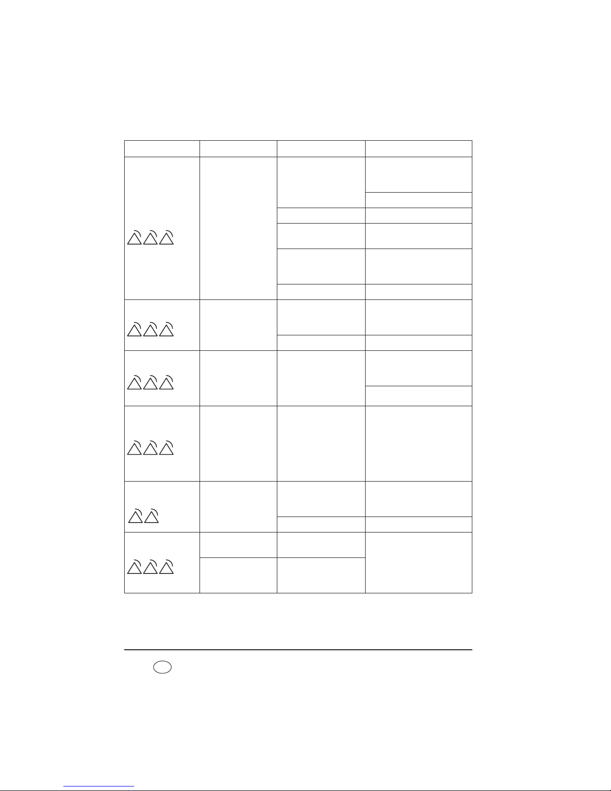
92 Troubleshooting
EN
Pressure
permanently
low
High priority
The valve control tube
between the device and
the patient valve is
incorrectly connected
Check valve control tube for
damage, replace patient
circuit if necessary
Connect valve control tube
Device defective Have device repaired
Implausible ventilation
settings
Have settings checked by the
doctor supervising treatment
Permanent large leak
Check patient circuit and
patient/ventilator interfaces
and change if necessary
Filter dirty Clean/change filter
VT
permanently low
High priority
Permanent large leak
Check patient circuit and
patient/ventilator interfaces
and change if necessary
Device defective Have device repaired
EPAP
high
High priority
The pressure drop on
exhalation is inadequate
(possible cause: pressure
drop at patient valve too
slow)
Ensure that the exhaled air
can escape freely at the
patient valve
Check tube system
Continuous pressure
High priority Device defective
Disconnect device from power
supply and switch off. Check
connections for tubes. Restore
power connection and
perform function check. If the
fault continues to occur, have
device repaired
Control voltage
failure
Medium priority
RS485 incorrectly
connected
Only use converter cable USBRS485 WM 93318 or
converter box WM 93316
Internal fault Have device repaired
Device start error
High priority
Parameters could not be
loaded
Have device repaired
High priority
Device switches off.
Blower does not switch
back on after power
failure
Display Alarm Cause of fault Remedy
Page 93
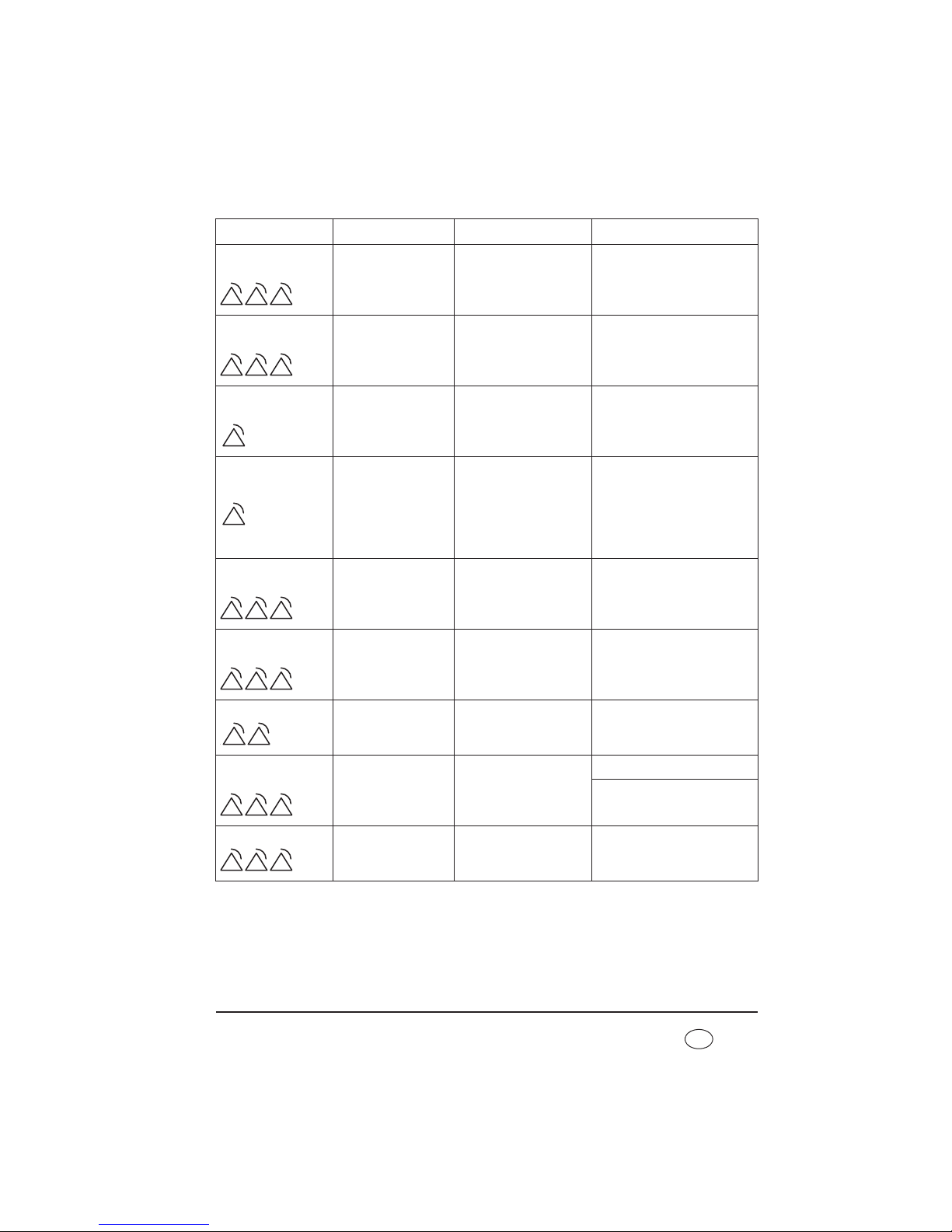
Troubleshooting 93
EN
IPC failure
Change device High priority
Device switches off.
Device defective Have device repaired
Sensor system failure
Change device High priority
Device switches off.
Sensor system defective Have device repaired
System monitoring
failure
Low priority
Voltage monitoring
failure
Have device repaired
No power supply
Low priority Power supply failed
Keep alternative ventilation
option to hand. Check power
cord is firmly connected. If
necessary, check the function
of the socket by connecting a
different device (e.g. a lamp)
Blower failure
Change device High priority
Device switches off.
Device defective Have device repaired
CPU failure
Change device High priority
Device switches off.
Internal processing
faulty, device defective
Have device repaired
I
2
C failure
Medium priority Device defective Have device repaired
Warning: Device
switched off!
High priority
Device has been
switched off
Turn the device on again
Acknowledge alarm
Unknown device
High priority Device defective Have device repaired
Display Alarm Cause of fault Remedy
Page 94

94 Troubleshooting
EN
8.2.6 Storage of alarms
Once the alarm threshold is reached, all the alarm types listed in tables “8.2.4 Physiological
alarms” and “8.2.5 Technical alarms” are recorded in an alarm list with date, time and
duration. Up to 200 alarms can be stored. After that, the oldest alarm in each case is
overwritten. The alarm list can be called up by the doctor supervising treatment or by you
(see “5.5 Alarm list” on page 56).
The alarm list is retained even if the entire power supply (power supply and internal battery)
fails. In this case, the data can be called up for up to two years. The alarm list is deleted
after two years or when maintenance is carried out.
In any event, alarms are retained in the event of a power failure.
8.2.7 Passing on of alarms via the remote alarm connection
All high and medium-priority alarms are switched to a remote alarm connection in parallel.
The only low-priority alarm which is passed on to the connection is the No power supply
alarm.
If the device is operated in a hospital, the therapy device can be connected to the hospital’s
nurse call system via the remote alarm connection.
For home ventilation, the therapy device can also be connected to the VENTIremote alarm
box via the remote alarm connection. The remote alarm box remotely transmits and
amplifies the acoustic and visual alarm signals output by the therapy device. It is of
particular assistance to nursing staff and to relatives when looking after the patient in the
home environment.
Page 95

Maintenance and safety checks 95
EN
9. Maintenance and safety checks
9.1 Intervals
We recommend having servicing, safety checks and repair work carried out only by
the manufacturer, Weinmann, or by a specialized dealer expressly authorized by
the manufacturer.
Check both filters regularly for dirt.
• The coarse dust filter and the fan filer should be cleaned once a week and
changed no later than every 6 months.
• The fine filter must be changed after no more than 1000 operating hours (filter
change symbol appears in the display).
For hygiene reasons, we recommend replacing the following parts at the intervals
specified.
9.1.1 Leakage ventilation
• Pressure measuring tube every 6 months - earlier if dirty
• Clean the patient/ventilator interface in accordance with the relevant
instructions for use
• Clean the exhalation system in accordance with the relevant instructions for use
• If necessary, other accessories in accordance with the associated operating
instructions
9.1.2 Valve ventilation
• The patient circuits with patient valve should be replaced in accordance with the
relevant instructions for use
• Clean the patient/ventilator interface in accordance with the associated
instructions for use
• If necessary, other accessories in accordance with the associated instructions for
use
Page 96

96 Maintenance and safety checks
EN
9.1.3 Internal battery
• Have the internal battery replaced by Weinmann or an authorized specialist
dealer at least every 2 years.
9.1.4 Replaceable battery (if present)
• Have the replaceable battery checked by Weinmann or an authorized specialist
dealer after 2 years.
• Replace the replaceable battery after no more than 4 years.
9.2 Batteries
The internal battery and the replaceable battery (if present) are maintenance-free.
9.2.1 Care of batteries
Warning!
An alternative ventilation option (e.g. a replacement device or manual ventilating
bag) must be used during maintenance of the internal battery for patients
dependent on a ventilation device. The internal battery may not be maintained with
patient ventilation in progress.
To prolong the life of your batteries, we recommend the measures below:
• Run down the battery completely every 6 to 12 months by running the device
without a power cable using the red test adapter until the device switches to the
internal battery/switches off and then recharge the battery completely. This
increases the accuracy of the capacity display. You should also observe the
maintenance intervals for the internal battery (see “9.1.3 Internal battery” on
page 96) and the replaceable battery (see “9.1.4 Replaceable battery (if
present)” on page 96).
Note
When the device is being operated with the red test adapter, alarms may occur as
a function of device settings (see “8.2 Alarms” on page 83).
Page 97

Maintenance and safety checks 97
EN
9.2.2 Storage
Internal battery
If the device is to be operational at all times, we recommend leaving the device connected
to the power supply even if it is not used for prolonged periods. This ensures that the
battery is always fully charged.
Replaceable battery (if present)
If storing the battery for more than a week, store it separately from the device.
Note the information below for storage:
• Always store the replaceable battery at room temperature
• Check the charge status of the replaceable battery every 2 months (see “5.3.4
Operation with replaceable battery” on page 54).
• Wait until just one segment is showing in the status line before charging the
battery.
• Replaceable batteries which have been stored for over a month must be charged
up before they are used to guarantee an accurate display.
9.3 Change filter
9.3.1 Change coarse dust filter
Use original filters from Weinmann only. Using third-party filters invalidates any claim
under warranty and may result in restricted function and bioincompatibility.
1. Press on the latch of the filter compartment lid and
take it off.
2. Take the coarse dust filter out of the filter
compartment
lid and dispose of it in normal domestic waste.
3. Place the clean coarse dust filter in the filter
compartment lid.
4. Put the filter compartment lid into the cutout in the
housing bottom edge first. Then push the filter
Page 98
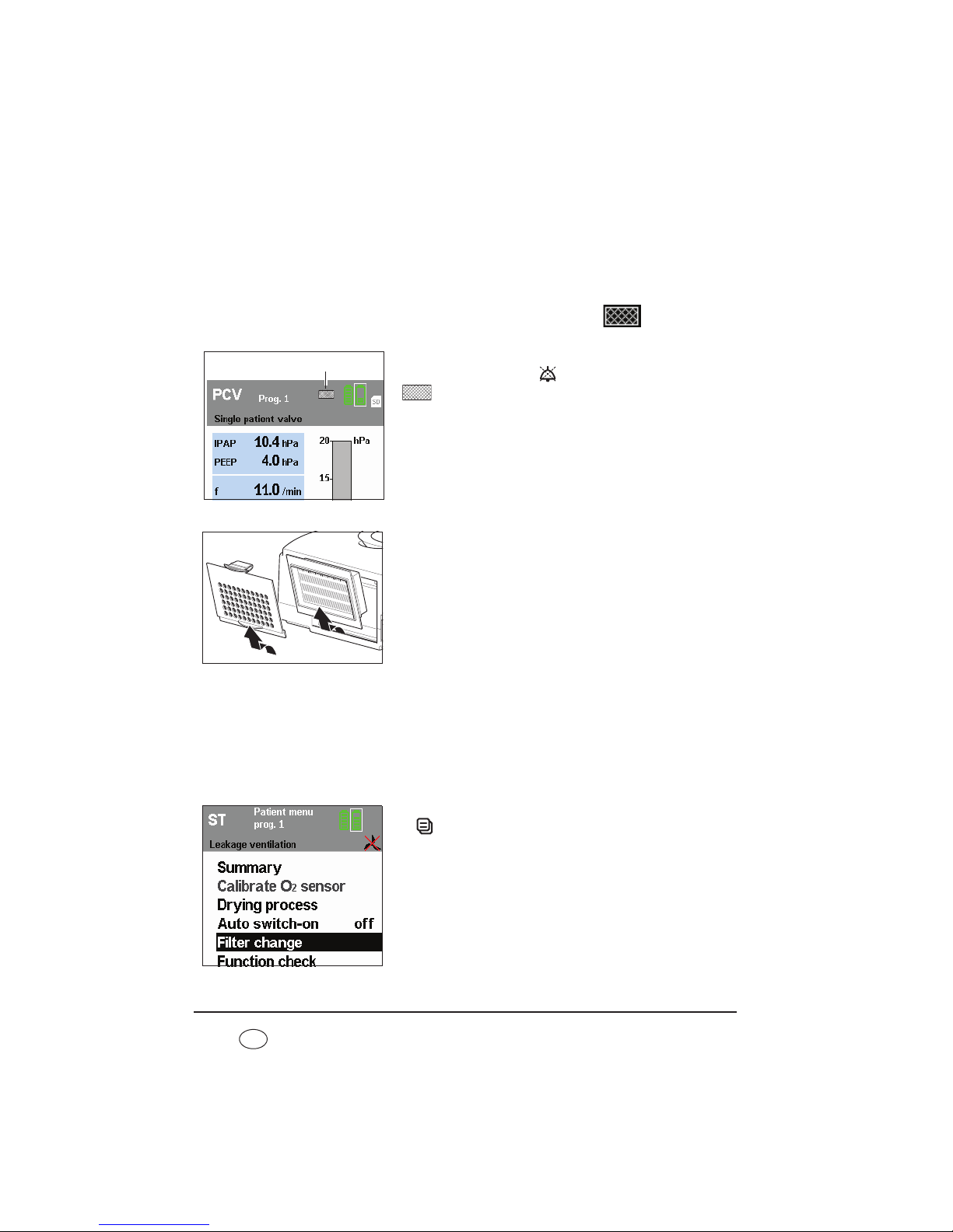
98 Maintenance and safety checks
EN
compartment lid into the housing until the latch
engages.
9.3.2 Change fine filter
The fine filter needs changing when it has gone dark, but in any event after no more than
1000 operating hours. In the latter case, the filter change indicator
appears in the
display.
Acknowledge the message by pressing the alarm
acknowledgement key . The filter change symbol
then appears permanently in the status line.
Proceed as follows to change the fine filter:
1. Press on the latch of the filter compartment lid and
take it off.
2. Replace the fine filter with a new fine filter
WM 15026. Dispose of the old filter in normal
domestic waste.
3. Put the filter compartment lid into the cutout in the
housing bottom edge first. Then push the filter
compartment lid into the housing until the latch
engages.
Reset filter change indicator
After you have changed the fine filter, you must reset the filter change indicator. This is
necessary even if the filter was changed before 1000 operating hours expired so the filter
change symbol was not in the display.
1. To reset the filter change indicator, press the menu key
and use the the dial to select Filter change from
the patient menu. Press the dial to call up the Filter
change menu.
Filter change indicator
Page 99

Maintenance and safety checks 99
EN
2. The question Reset filter change? appears. Select
YES with the dial and confirm the selection by pressing
the dial.
If you want to cancel the process, select NO with the
dial and press the dial. The process is cancelled.
If you select and confirm YES with the dial, the
message Filter change reset!appears for approx. 3
seconds.
9.3.3 Change fan filter
Proceed as follows to change the fan filter.
1. Turn the device over so that the underneath points upwards.
2. Grasp the fan filter with your fingertips and pull it out of the opening.
3. Take a new clean filter and put it in. Ensure that the
fan filter is straight and that the corners are not tilted
by the opening.
4. Turn the device back over so that the top points
upwards.
5. Dispose of the used filter with domestic waste.
9.3.4 Bacteria filter
When using bacteria filter WM 24148, change the particulate filter in the bacteria filter in
accordance with the associated instructions for use.
When using bacteria filter WM 27591, change the bacteria filter in accordance with the
associated instructions for use.
Page 100

100 Maintenance and safety checks
EN
9.4 Change pressure-measurement tube
(only leakage ventilation)
1. Release the sleeve of the creased tube from the
adapter.
2. Pull the pressure-measurement tube out of the
creased tube.
3. Pull the pressure-measurement tube off the adapter.
4. Push the new pressure-measurement tube onto the
adapter.
5. Hold up the creased tube and guide in the free end of
the new pressure measuring tube.
6. Push the sleeve of the creased tube onto the adapter.
7. Dispose of the old pressure-measurement tube.
9.5 Safety check
The legally-specified interval for performance of the safety check (Sicherheitstechnische
Kontrolle - STK) in accordance with §6 of the German law governing medical devices
[Medizinprodukte-Betreiberverordnung - Germany only] is 2 years.
In addition, servicing must be carried out as a preventive measure by the manufacturer,
Weinmann, or by a specialist dealer expressly authorized by the manufacturer, at the
following intervals:
• after every 8000 operating hours (servicing symbol
appears in the display)
or
• after 2 years (see service label on the rear of the device)
depending on which comes first.
The safety check and servicing include:
– check for completeness
Adapter
Pressuremeasurement
tube
Sleeve
 Loading...