

Page 1
INSTRUCTION HANDBOOK
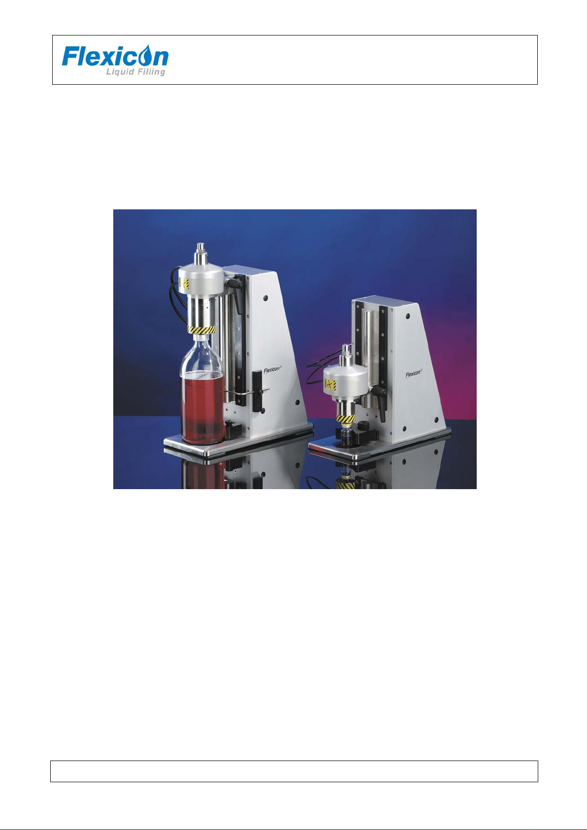
FS10, FS32
FS32 & FS10
(example; exact model may vary)
This instruction handbook is for the daily users of the equipment.
FS10-32 IH EN 74-215-021 v1.02.doc Version: 1.02 Page 1 of 17
Page 2

INSTRUCTION HANDBOOK
FS10, FS32
Table of Contents
1 Introduction .............................................................................................................................. 3
1.1 FS10 / FS32 ............................................................................................................................ 3
1.2 Abbreviations in this manual .................................................................................................... 3
1.3 Symbols on the machine ......................................................................................................... 3
1.4 Caution and employee safety .................................................................................................. 4
1.5 Essential training before daily use ........................................................................................... 4
1.6 References .............................................................................................................................. 4
1.7 Dismantling and disposal ......................................................................................................... 4
2 General information ................................................................................................................. 5
2.1 Unpacking and inspection ........................................................................................................ 5
2.2 Receiving and storing the FS10/FS32 ..................................................................................... 5
2.3 Mounting of capping head ....................................................................................................... 5
2.4 Technical specifications ........................................................................................................... 6
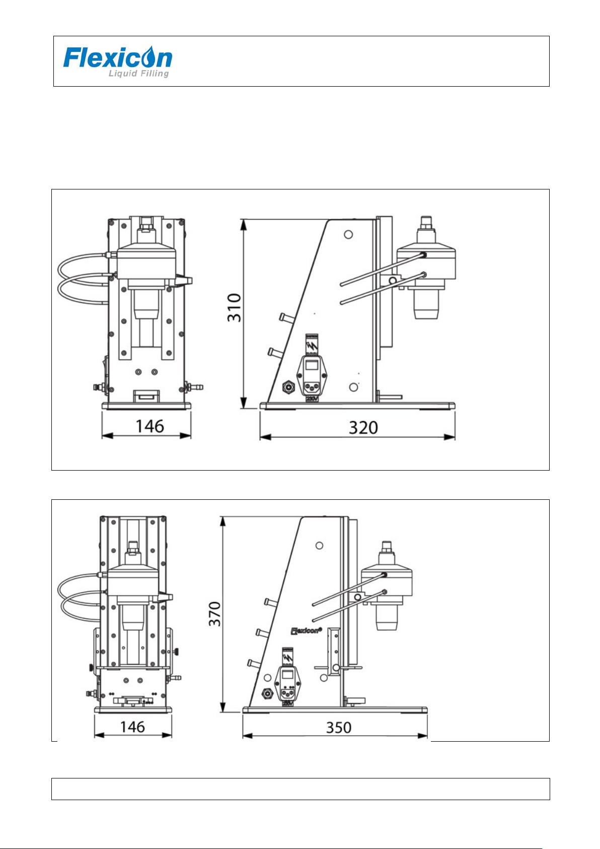
2.4.1 Dimensions .............................................................................................................................. 6
2.4.2 Buttons / Connections.............................................................................................................. 7
2.4.3 Services .................................................................................................................................. 8
2.4.4 Bottles and caps ...................................................................................................................... 8
2.4.5 Ingress protection .................................................................................................................... 8
2.4.6 Weight ..................................................................................................................................... 8
2.4.7 Materials .................................................................................................................................. 8
3 Installation ............................................................................................................................... 9
3.1 Connections ............................................................................................................................ 9
3.2 Mounting of capping head ..................................................................................................... 10
3.3 Mounting of bottle tool ........................................................................................................... 11
4 Adjustments ........................................................................................................................... 11
4.1 Adjustment of the height of the capping head ........................................................................ 11
4.2 Adjustment of the stroke length of piston in capping head ..................................................... 12
5 Daily Use ............................................................................................................................... 13
5.1 Production START and STOP ............................................................................................... 13
5.2 Starting-up and running ......................................................................................................... 13
6 Malfunctioning ....................................................................................................................... 14
6.1 Function errors / Trouble shooting ......................................................................................... 14
7 Cleaning ................................................................................................................................ 15
7.1 Cleaning Frequency .............................................................................................................. 15
7.2 Preparations for cleaning ....................................................................................................... 15
7.3 Cleaning Guidance ................................................................................................................ 15
7.4 Detergents or cleaning agents ............................................................................................... 15
8 Maintenance & service .......................................................................................................... 16
8.1 Service .................................................................................................................................. 16
8.2 Methods and frequency of inspections for safety functions .................................................... 16
9 Accessories ........................................................................................................................... 16
10 Declaration of conformity ....................................................................................................... 17
FS10-32 IH EN 74-215-021 v1.02.doc Version: 1.02 Page 2 of 17
Page 3

INSTRUCTION HANDBOOK
App.
Approximately
Hz
Hertz
IH
Instruction Handbook
Max.
Maximum
PE
Protective Earth (electrical units safety measure)
SOP
Standard Operating Procedure
VAC
Volt Alternating Current
WMF
Watson-Marlow Flexicon a/s
FS10, FS32
1 Introduction
1.1 FS10 / FS32
FS10 and FS32 are both semi-automatic capping machines designed for crimping aluminium caps.
FS10 is designed for crimping 8 mm, 13 mm and 20 mm standard crimp caps* with or without flip-off
plastic disc.
FS32 is mainly designed for 20mm and 32 mm caps*, also with or without flip-off plastic disc.
Crimping is performed by pressing the bottle or vial against the bottle holder. This causes the crimp
head to move down onto the bottle, the jaws close around the cap, pressure is applied, the jaws
release and the head lifts again.
All used compressed air is collected and can be removed through a hose mounted on the side of the
cabinet.
*ISO 8362
1.2 Abbreviations in this manual
1.3 Symbols on the machine
Warning against touching Warning against high voltage
FS10-32 IH EN 74-215-021 v1.02.doc Version: 1.02 Page 3 of 17
Page 4
INSTRUCTION HANDBOOK
WM-Flexicon machines may not be disposed using normal refuse
*
FS10, FS32
1.4 Caution and employee safety
This manual should be read before using the FS10/FS32.
It is strongly advised that
- Any kind of maintenance or cleaning of the machine not is carried out while power is
connected
- Unauthorised / non-trained personnel should not maintain the electrical parts
- The machine is placed in such a way that it is not exposed to high humidity, high temperatures
or other abnormal operating environment.
- FS10 / FS32 is used for capping bottles, only
1.5 Essential training before daily use
Read the section with Daily Use, thoroughly before using the machine.
Protective equipment and protective devices are installed:
If fingers accidently are placed on the top of the bottle while the crimp head is going down,
crimping will not take place. If the inner side of crimp head is prohibited to “rest” on the top of
the cap it will return to top position.
Always respect the warning symbols on the machine.
Cleaning must be performed as described in this IH.
1.6 References
N/A
1.7 Dismantling and disposal
Prior to dismantling, it must be observed that all services are disconnected, and connections to other
equipment are removed.
collection. The machines must be collected and disposed separately as
they contain electrical components such as batteries, electrolyte
capacitors, liquid crystal displays and printed circuit boards.
Further information is available on www.wmflexicon.dk.
* (WEEE) DS/EN 50419
FS10-32 IH EN 74-215-021 v1.02.doc Version: 1.02 Page 4 of 17
Page 5

INSTRUCTION HANDBOOK
FS10, FS32
2 General information
2.1 Unpacking and inspection
Please check that all ordered items have been received and that no items are damaged during
transport. In case of any defects or omissions, please contact WMF or your supplier immediately.
2.2 Receiving and storing the FS10/FS32
Before unpacking or storing of the FS10/FS32 it should be checked if the crate is damaged.
In case of long -term stor age of t he FS10/FS32 before installation, the machine must be stored in the
crate, and placed in a dry room. The crate is not water resistant.
2.3 Mounting of capping head
If the capping head has been removed during shipping it is mounted as described in section 3.2
FS10-32 IH EN 74-215-021 v1.02.doc Version: 1.02 Page 5 of 17
Page 6
2.4 Technical specifications
2.4.1 Dimensions
FS10
INSTRUCTION HANDBOOK
FS10, FS32
FS32
FS10-32 IH EN 74-215-021 v1.02.doc Version: 1.02 Page 6 of 17
Page 7

2.4.2 Buttons / Connections
INSTRUCTION HANDBOOK
FS10, FS32
ON/OFF Button / Emergency stop
Power indicator; lights when power is on.
OFF is used for emergency stopping.
Power supply connection
Compressed air connection
Exhaust filter and air collection
FS10-32 IH EN 74-215-021 v1.02.doc Version: 1.02 Page 7 of 17
Air tubes for the crimp head
Page 8

50/60Hz
Note:
Only authorised personnel can gain access to the installations. The main
installations are touched.
DIN standard
flip-top
Cabinet
Anodised aluminium
Closing head
Hardened steel jaws
housing
2.4.3 Services
All electrical systems are placed inside the machine.
INSTRUCTION HANDBOOK
FS10, FS32
Power supply:
Consumption: 50 W
Compressed air: 6 bar, clean and dry air
Consumption, FS10:
Consumption, FS32:
110/230 VAC earthed,
35 L/min. free air
50 L/min. free air
power cable must be removed completely from power supply before the
2.4.4 Bottles and caps
Bottle sizes
Max. Diameter 55 mm 95 mm
Max. Height 180 mm 240 mm
Cap sizes
FS10 FS32
FS10 FS32
With or without
8-20 mm 20-32 mm
2.4.5 Ingress protection
Ingress protection IP31
2.4.6 Weight
Weight, FS10 app. 12 kg
Weight, FS32 App. 16 kg
2.4.7 Materials
Anodised aluminium
FS10-32 IH EN 74-215-021 v1.02.doc Version: 1.02 Page 8 of 17
Page 9

INSTRUCTION HANDBOOK
2 1
3 Installation
3.1 Connections
FS10 / FS32 must be placed on a stable and horizontal bedplate.
The mains cable (1) is
connected to a singlephase power supply with
earth.
The plug box (1) contains 2
fuses. When the cover of fuse
box is removed 1 more fuse is
found inside the machine.
Compressed air is
connected to (2) by use
of the supplied quick
release clutch.
FS10, FS32
Please contact your supplier or WMF IF the machine is not made for your local power supply. The sign on the machine indicates the
value of power (110/120 VAC or 220/240 VAC). The frequency has no influence.
or
If the delivered power cable does not match your socket,
FS10-32 IH EN 74-215-021 v1.02.doc Version: 1.02 Page 9 of 17
Page 10

3
4
All exhaust air is collected
and exhausted through the
air exhaust filter (2)
A hose connection can be
mounted in order to
“remove” the process air
form the capping area; but
the machine will function
even if no hose is mounted.
INSTRUCTION HANDBOOK
FS10, FS32
The tubes (4) are mounted
on the capping head.
The upper tube on the
upper connection and the
lower on the lower
connection
3.2 Mounting of capping head
Loosen the
handle on the
side of the
capping head and
mount the head
gently on the
slide bar.
Tighten the
handle.
Re-mount the air
tubes on the
capping head
Changing of capping head is done the opposite way as mounting.
FS10-32 IH EN 74-215-021 v1.02.doc Version: 1.02 Page 10 of 17
Page 11

INSTRUCTION HANDBOOK
IN
OUT
FS10, FS32
3.3 Mounting of bottle tool
Place the bottle
tool on the
bracket and
mount the screw.
Note: If the bottle tool is mounted too close to the machine the switch function will not work, see
section 4.1
4 Adjustments
4.1 Adjustment of the height of the capping head
Before starting the production the initial height of the capping head and the bottle tool should both be
adjusted.
Begin with the bottle tool; for safety reasons switch the power OFF
Place a bottle on the base plate under the capping head.
Loosen the handle “B” and lower the capping head until it is just above the bottle neck.
Now adjust the bottle tool so the bottle is centred under the capping head – WHEN THE BOTTLE
TOOL IS PUSHED “IN”
Now FS10 is ready for height adjustment.
FS10-32 IH EN 74-215-021 v1.02.doc Version: 1.02 Page 11 of 17
Page 12
INSTRUCTION HANDBOOK
FS10, FS32
Connect compressed air and power. Turn power ON.
Choose the spacer (D) which best fits the capping head on the machine.
Place a bottle under the capping head – With NO stopper or cap in place.
Place the spacer on the capping head, so that it fits on the capping head.
Loosen the handle (B), press the capping head down until it rests firmly on the bottle.
It should be so firm, that the bottle can only be removed by the use of some force.
Tighten the handle (B) again. Remove bottle and spacer. The height is now roughly adjusted.
For final adjustment, a few vials should be capped and crimped.
Examine the results and if necessary make adjustments according to trouble shooting table, see
section 6.1
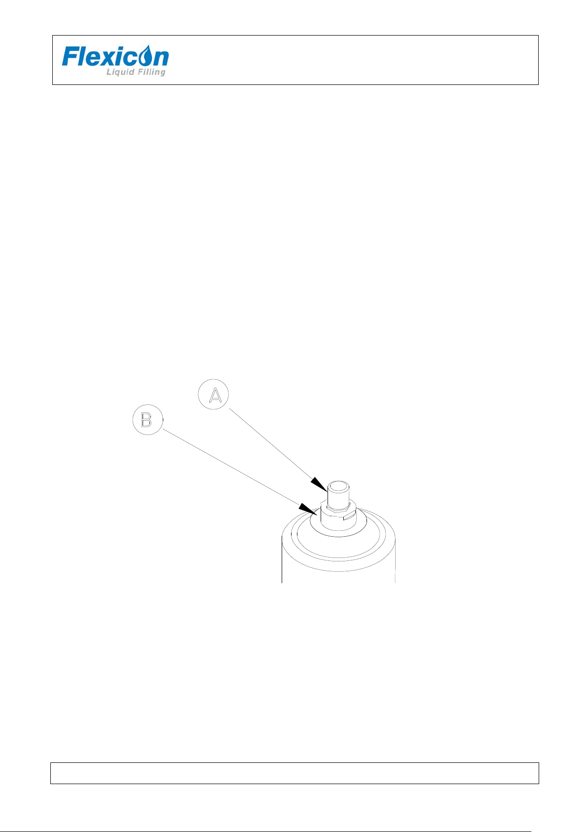
4.2 Adjustment of the stroke length of piston in capping head
Under normal condition it is possible to operate with full stroke length on the piston, but in certain
combination of cap and bottle ring tolerances, the cap might fold when hitting the bottle neck.
If this happens, the stroke length can be adjusted as following:
1. Loosen the nut (A) and screw down the piston cap (B).
2. While holding contra on the piston cap with the key surface, the nut is tightened.
3. Repeat the procedure until the cap is crimped satisfactorily.
FS10-32 IH EN 74-215-021 v1.02.doc Version: 1.02 Page 12 of 17
Page 13

INSTRUCTION HANDBOOK
FS10, FS32
5 Daily Use
5.1 Production START and STOP
FS10/FS32 is ready for production start when:
Section 3 has been completed
The height of the capping head has been set (section 4.2.1)
and the Power signal is ON
5.2 Starting-up and running
The bottle with cap is placed in the bottle tool, which is activated by pressing it towards the rear of the
machine. The capping head moves down onto the cap and bottle.
The bottle tool activates a micro switch which releases the compressed air; the capping head then
descends on the cap by its own weight. In case something prevents the capping head (e.g. a finger)
in encircling the cap, a stroke will not be achieved. When the capping head is in position over the cap,
a micro switch is activated in order to activate the jaws.
The jaws crimp the cap on the bottle and then the capping head returns to its upper position.
FS10-32 IH EN 74-215-021 v1.02.doc Version: 1.02 Page 13 of 17
Page 14

INSTRUCTION HANDBOOK
Problem:
Crimping leaves marks on the cap skirt, and crimping is not tight.
Reason:
Capping head is too high.
Action:
Lower capping head.
Problem:
Caps are closed on the bottle neck.
Caps skirts are too long for stopper-vial combination.
Too long stroke.
Check combination of rubber stopper, vial and cap.
Adjust the stroke. (see section 4.2)
Problem:
Crimping is done on the rim of caps.
Too short stroke.
Cap skirt is too short.
Make an adjustment of the stroke.
Check rubber stopper’s head for thickness.
Cap is not crimped tight. Cap is crimped too tight.
Incorrect height of crimp head.
Dirty/worn jaws.
Adjust the crimp head height slightly. Lower is tighter – Higher is looser.
Clean and polish the jaws; please contact your supplier or WMF
FS10, FS32
6 Malfunctioning
6.1 Function errors / Trouble shooting
FS10/FS32 is a relatively simple machine to operate and normally errors will be due to incorrect
adjustment of certain functions.
In the table below, the most common faults are described and what causes it.
Or the caps are deformed. (harmonica deformation)
Reason:
Action:
Reason:
Action:
Problem:
Reason:
Stroke length incorrect.
Action:
FS10-32 IH EN 74-215-021 v1.02.doc Version: 1.02 Page 14 of 17
Make an adjustment of the stroke.
Page 15

INSTRUCTION HANDBOOK
Cleaning of parts
May
autoclaved
Can be cleaned
alcohol 70%
Can be cleaned with
wiped off with dry a cloth
Anodized aluminium
Nylon
(Compressed Air tubes)
FS10, FS32
7 Cleaning
7.1 Cleaning Frequency
As FS10/FS32 is not in direct contact with the dispensed product, daily cleaning might not be
necessary.
Cleaning might be determined by local SOP’s and cleaning validations; but must never be with
detergents more potent than the ones below.
7.2 Preparations for cleaning
Before cleaning the machine:
Turn off the power
Remove the capping head and the air tubes
7.3 Cleaning Guidance
Correct cleaning of the FS10/FS32 is carried out by washing it off with water or deter gents, using a
lint-free firmly wrung cloth or lint-free paper towel; subsequently the machine is wiped off with a dry
cloth.
7.4 Detergents or cleaning agents
Normal cleaning agents such as tepid/medium hot water, ethyl alcohol (ethanol) 70% and may be
used all over the machine.
The FS10/FS32 can be cleaned in several ways:
made of:
Recommendation: Keep a log on the cleaning in order to keep a sense of perspective.
be
X X X
X
with ethyl
water and afterwards
FS10-32 IH EN 74-215-021 v1.02.doc Version: 1.02 Page 15 of 17
Page 16

INSTRUCTION HANDBOOK
FS10, FS32
8 Maintenance & service
8.1 Service
Should service be needed, please contact W-M Flexicon or your local supplier.
8.2 Methods and frequency of inspections for safety functions
Safety functions should be tested once a year:
Emergency switch
When pressed the compressed air is switched off
Keep a log and read the previous log recordings to present an overview of the machines state.
After testing the safety functions the results must be recorded in the log.
9 Accessories
For FS10/FS32 a number of standard capping heads are made as well as capping heads for special
purposes. The mounted standard bottle tool covers most bottle sizes, but customised bottle tools can
also be delivered.
FS10-32 IH EN 74-215-021 v1.02.doc Version: 1.02 Page 16 of 17
Page 17

INSTRUCTION HANDBOOK
Flex Seal type
Item no
Model
FS10
93-100-100
63-100-020
FS32
93-100-110
63-100-050
DS EN/ISO 12100
Safety of machinery - Basic concepts, general
principles of design
DS/EN 60204
Safety of machinery – Electrical equipment of
machines
2006/42/EC
On the approximation of the laws of the Member
States relating to machinery
2006/95/EC
On the harmonization of the laws of Member
for use within certain voltage limits
2004/108/EC
On the approximation of the laws of the Member
States relating to electromagnetic compatibility
Ringsted, Denmark
10 Declaration of conform ity
We Watson-Marlow Flexicon A/S
Frejasvej 2-6
DK-4100 Ringsted
Declare on our sole responsibility that the flex seal:
to which this declaration relates is in conformity with the following standard(s):
FS10, FS32
According to the provisions in the Directives:
States relating to electrical equipment designed
Signature:
October, 2012
Jørn Jeppesen, Development Manager
FS10-32 IH EN 74-215-021 v1.02.doc Version: 1.02 Page 17 of 17
 Loading...